1
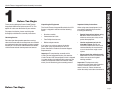
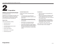
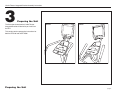
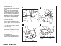
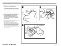
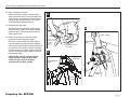
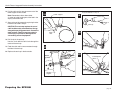
®
EFX Integrated LCD Screen Option
Cardio Theater Integrated Bracket Assembly Instructions
Cardio Theater Integrated Bracket Assembly Instructions
Table of Contents
Table of Contents
1
Before You Begin .............................................................................................
4
Obtaining Service ........................................................................................................................
Unpacking the Equipment ...........................................................................................................
Important Safety Instructions ......................................................................................................
4
4
4
2
Preparations.....................................................................................................
5
Required Tools .............................................................................................................................
Installation Requirements ............................................................................................................
Assembly Tips ............................................................................................................................
5
5
5
3
Preparing the Units..........................................................................................
6
4
5
6
7
Install the Bracket Assembly .......................................................................... 20
Preparing the EFX546i ................................................................................................................ 7
Preparing the EFX556i ................................................................................................................ 14
Attach the LCD Screen ................................................................................... 22
Reinstall the Bracket Cover ............................................................................ 24
Connect the Controller and the Cables ......................................................... 25
page 3
1
Before You Begin
Thank you for adding the Precor Cardio Theater
Integrated LCD Screen Option to your EFX®. This
option will add a new dimension to your workout.
For proper installation, please read this guide
thoroughly and follow the assembly instructions.
Obtaining Service
For information about product operation or service,
refer to the Precor web site at www.precor.com. Should
you need more information regarding customer support
numbers or a list of Precor authorized service centers,
visit the Precor website at www.precor.com/contact.
Unpacking the Equipment
Important Safety Instructions
The Cardio Theater Integrated Bracket for the LCD
Screen is shipped in one box with the following
items:
When using exercise equipment, basic
precautions should always be taken,
including the following:
•
Bracket assembly
•
•
Power extension cable
•
Four Phillips-head screws
Read all instructions before using
the unit. These instructions are
written to ensure your safety and to
protect the equipment.
•
Rubber adapter mounts
•
Use the equipment only for its
intended purpose. Do not use
accessory attachments that are not
recommended by the manufacturer,
as such attachments might cause
injuries.
•
Always check the unit before each
use. Make sure that all fasteners and
cables are secure and in good
working condition.
If any items are missing, contact the dealer
from whom you purchased the unit or call a
Precor Commercial Products Customer Support
Representative.
Important: To complete the assembly of the
Cardio Theater Integrated Bracket, you need the
Cardio Theater LCD Screen Option, which is shipped
in a separate box. Included with the screen are two
cables (coaxial/power cable and controller cable),
which you will need during the assembly process.
Before You Begin
Important: The important safety
instructions written here reflect a portion
of what is found in the Precor EFX
owner’s manuals. Please review and
follow the safety instructions found there.
IMPORTANT SAFETY INSTRUCTIONS
Cardio Theater Integrated Bracket Assembly Instructions
page 4
Cardio Theater Integrated Bracket Assembly Instructions
2
Preparations
Important: To attach the Cardio Theater Integrated
Bracket, ask another adult for help. Do not attempt
the assembly by yourself.
Installation Requirements
Assembly Tips
Review these installation requirements before
assembly:
•
Read all the notes on each page before completing that step.
Remember to read and follow the instructions in this
guide. If you do not assemble the Cardio Theater
Integrated Bracket according to these guidelines,
you could void the Precor Limited Warranty.
•
The Cardio Theater Integrated Bracket is
built to VESA MIS-D, 100/75 standard interface
specifications.
•
While you may be able to assemble the Cardio
Theater Integrated Bracket using the illustrations only, important safety notes and other tips
are included in the text.
•
Provide ample space around the EFX. Open
space around the unit allows for easier access
and installation.
•
•
Open the box and assemble components
in the sequence presented in this guide.
Refer to the EFX owner’s manual for torque
wrench specifications. The handrail clamp and
upright support fasteners are not fully secure
until tightened using a torque wrench.
•
Leave room for adjustments. Tighten fasteners
(bolts, nuts, and screws) so the unit is stable, but
leave room for adjustments. Do not fully tighten
fasteners until instructed in the assembly steps
to do so.
Required Tools
Obtain these tools before assembly:
•
Standard hex key set
•
Standard socket set
•
½-inch box wrench or crescent wrench
•
Flat head screwdriver
•
Phillips-head screwdriver
•
Power drill with a ⁷⁄₈-inch drill bit
•
Standard torque wrench
Preparations
The assembly of the Cardio Theater Integrated
Bracket takes about ½ hour to complete.
page 5
Cardio Theater Integrated Bracket Assembly Instructions
3
Preparing the Unit
The illustration shows how the Cardio Theater
Integrated Bracket will look after you install it on
the EFX.
EFX546i
EFX556i
This section contains preparation instructions for
both the EFX546i and the EFX556i.
Preparing the Unit
page 6
Cardio Theater Integrated Bracket Assembly Instructions
Preparing the EFX546i
1
3
Rubber
grommet
Handrail clamp
1. Loosen the two screws on the handrail clamp
using a ⁵⁄₃₂-inch hex key.
Important: Leave the handrails in the clamp.
Do not remove the handrail clamp screws!
Handrail
Front
cover
2. Remove the front cover.
Loosen and remove the two screws securing
the front cover. Set the front cover and
fasteners aside.
3. Move rubber grommet.
Slide the rubber grommet along the upright
support toward the display.
4. Remove the back cover.
Loosen the two screws securing the back cover.
Slide the back cover away from its bracket and
set it aside.
Important: Do not remove the two screws
securing the back cover.
Display
console
Loosen the two screws on
the handrail clamp.
2
Back
cover
Rubber
grommet
Front
cover
Upright
support
Preparing the EFX546i
4
Back
cover
Upright
support
page 7
Cardio Theater Integrated Bracket Assembly Instructions
5. Remove the four fasteners securing the upright
support.
Use a ¼-inch hex and ½-inch box end wrench to
remove the fasteners. Keep the fasteners
together and within easy reach.
Important: Ask someone for help before
completing the next step.
5
6
Assistant must hold onto
the display console to
keep it from sliding.
Rubber
grommet
6. Separate the display console from its bracket.
Ask your assistant to hold the display console
while you remove the four screws from the back
of the display console bracket using a ⁵⁄₃₂-inch
hex key. If the display console slides off the
display console bracket, its weight can place
excessive pressure on the data cable.
Note: If no plug exists in the display console,
you will need to drill a hole using a ⁷⁄₈-inch drill
bit and electric drill.
Display
console
Upright
support
7. Remove the plastic plug.
Use your thumbs to pop the plastic plug from
the display console bracket. Discard the plug.
Display
console
bracket
7
Display
console
bracket
Plastic
plug
Preparing the EFX546i
page 8
Cardio Theater Integrated Bracket Assembly Instructions
8. Attach the power extension cable to the power
connector on the coaxial/power cable.
8
Locate the coaxial/power cable provided with
the LCD Screen. One end of the coaxial/power
cable has three connectors; the other end has
two connectors. Attach the power extension
cable to the power connector on the end with
the two connectors (coaxial and power).
Handrail
Power connector
Display
console
bracket
9. Feed the coaxial/power cable with its connectors through the display console bracket.
Insert the coaxial/power cable with its two
connectors up through the hole in the display
console bracket.
10. Feed the coaxial/power cable with its connectors through the upright support.
Note: Leave about 3 feet (1 meter) of the
coaxial/power cable with its three connectors
(coaxial, power, and DVD) hanging out of the
hole in the display console bracket. This portion
of the cable will be fed through the bracket
assembly before it is attached to the back of
the display console.
9
Power extension
cable
Display
console
10
Coaxial/power
cable
Display
console
bracket
Data
cable
Upright
support
Preparing the EFX546i
Display
console
page 9
Cardio Theater Integrated Bracket Assembly Instructions
11. Secure the display console.
Replace two of the screws at the base of
the console bracket. Do not fully tighten the
screws. Leave space between the screw head
and the display console bracket. The bracket
assembly slides in between the two.
Note: Once the display is secure, your assistant
can let go of the display.
Display console
12. Pry the rubber end cap off the base.
Use a flat head screwdriver.
Display
console
bracket
13. Slide the upper support away from lower
support.
Ask your assistant to hold the upper support
away from the lower support. With the small
gap that is created, pull the coaxial and power
extension cables out from the base of the upper
support.
End cap
12
11
Replace the two screws at the
base of the display console.
Leave room between the
display console bracket and
screw heads.
13
Upper
support
Slide
bracket
apart to
access
Lower cables.
Support
Preparing the EFX546i
page 10
Cardio Theater Integrated Bracket Assembly Instructions
14. Continue to feed the cable with its connectors
through the lower support.
Start with the coaxial and power extension
connectors. Feed them into the lower support.
Continue to slide the cable and its connectors
so no excess remains at the gap between the
upper and lower supports. Ask your assistant to
release pressure on the upper support and
realign the mounting holes between the upper
and lower supports.
CAUTION: Be careful! A height adjuster screw
protrudes inside the base tube. Cables can
get caught and fingers scratched on the
screw threads.
15. Pull the cable and its connectors out of the
lower support and base tube.
Note: Remember to leave about 3 feet
(1 meter) of cable hanging out of the hole in the
display console bracket.
CAUTION: The next step requires the use of
a drill and the safety considerations that go
along with operating power tools. Protect the
work surfaces. Take the necessary steps to
avoid injury to yourself or damage to the
surrounding area and equipment.
16. Drill a hole in the end cap.
Use the ⁷⁄₈-inch drill bit to drill a hole through the
center of the end cap.
Read CAUTION above step 16.
Upper
support
16
17
14
End cap
15
Lower
support
Base tube
18
17. Feed the cable and its two connectors through
the hole in the end cap.
18. Replace the end cap in the base tube.
End cap
Power connector
Preparing the EFX546i
Coaxial
connector
page 11
Cardio Theater Integrated Bracket Assembly Instructions
19. Secure the upright support by replacing the four
fasteners set aside in step 5.
20. Retighten the two handrail clamp screws.
Important: Look underneath the handrail clamp
at the gap between the handrails. The area
between the ends of the handrails should be no
larger than a ¼-inch gap. If necessary, push the
handrails toward each other before tightening
the screws.
21. Replace the back cover and rubber grommet.
Replace the back cover onto the upright
support. Fit the lip of the back cover into the
tabs along the inside surface of the grommet.
Apply pressure to the top of the back cover
while you tighten the screws.
Handrail clamp
Handrail
Rubber
grommet
Upright
support
Display
console
19
20
Slide rubber grommet
down so it fits snugly
against the back cover.
21
Back
cover
Back
cover
Upright
support
Preparing the EFX546i
page 12
Cardio Theater Integrated Bracket Assembly Instructions
22. Reinstall the front cover and secure it with the
two screws removed in step 2.
Before tightening the front cover, be sure to fit
the lip of the front cover into the tabs along the
inside surface of the grommet.
22
Upright
support
To complete the installation, refer to the instructions
on page 19.
Front
cover
Front
cover
Upright
support
Preparing the EFX546i
page 13
Cardio Theater Integrated Bracket Assembly Instructions
Preparing the EFX556i
1
3
Rubber
grommet
1. Pry the rubber end cap off the base using a flat
head screwdriver. Set the end cap aside.
2. Remove the front cover.
Loosen and remove the two screws securing the
front cover. Set the front cover and fasteners
aside.
Front
cover
3. Move rubber grommet.
Slide the rubber grommet along the upright
support toward the display.
End cap
4. Remove the back cover.
Loosen the two screws securing the back
cover. Slide the back cover away from its
bracket and set it aside.
2
4
Back
cover
Rubber
grommet
Front
cover
Important: Do not remove the two screws
securing the back cover.
Upright
support
Preparing the EFX556i
Back
cover
Upright
support
page 14
Cardio Theater Integrated Bracket Assembly Instructions
Important: Ask someone for help before
completing the next step.
5. Remove the four fasteners securing the upright
support.
Ask your assistant to hold the upper support
while you use a ¼-inch hex and ½-inch box
end wrench to remove the four fasteners that
secure the upright support. Keep the fasteners
together and within easy reach.
Important: A data cable runs the length of the
upright support. Do not separate the upper
support from the lower support until you have
disconnected the cable in the next step.
5
8. Separate the display console from its bracket.
Remove the four screws from the back of the
display console bracket using a ⁵⁄₃₂-inch hex
key. Secure the display console so its weight
does not place excessive pressure on the data
cable.
Upper
support
Rubber
grommet
Data
cable
6. Disconnect the data cable.
Ask your assistant to gently lift the upper
support to expose a gap between the upper
and lower supports. Access the data cable and
disconnect it.
7. Lay the upper support and display console on
a clean work surface.
6
Upright
support
Lower
support
8
9
Display
console
9. Remove the plastic plug.
Use your thumbs to pop the plastic plug from
the display console bracket. Discard the plug.
Display
console
bracket
Preparing the EFX556i
Display
console
bracket
Plastic
plug
page 15
Cardio Theater Integrated Bracket Assembly Instructions
10. Attach the power extension cable to the power
connector on the coaxial/power cable.
Locate the coaxial/power cable provided with
the LCD Screen. One end of the coaxial/power
cable has three connectors; the other end has
two connectors. Attach the power extension
cable to the power connector on the end with
the two connectors (coaxial and power).
Coaxial connector
Power
connector
11. Feed the coaxial/power cable with its connectors through the display console bracket.
Insert the coaxial/power cable with its two
connectors up through the hole in the display
console bracket.
12. Feed the coaxial/power cable with its connectors through the upright support.
Note: Leave about 3 feet (1 meter) of the
coaxial/power cable with its three connectors
(coaxial, power, and DVD) hanging out of the
hole in the display console bracket. This portion
of the cable will be fed through the bracket
assembly before it is attached to the back of
the display console.
11
10
Power
connector
Power extension
cable
12
Display
console
bracket
Coaxial/power
cable
Upper
support
Preparing the EFX556i
page 16
Cardio Theater Integrated Bracket Assembly Instructions
13. Secure the display console.
Replace two of the screws at the base of the
display console bracket. Do not fully tighten the
screws! Leave space between the screw heads
and the display console bracket. The bracket
assembly slides in between the two.
13
Display console
14. Reconnect the data cable.
Ask your assistant to hold the upper support
above the lower support while you reconnect
the data cable. Push the connection into the
lower support tube.
15
Upper support
15. Slide the coaxial/power cable with its two
connectors through the lower support.
While your assistant holds the upper support,
continue feeding the ends of the coaxial/power
cable into the lower support. Slide the cable and
its connectors so no excess remains at the gap
between the upper and lower supports. Ask your
assistant to lower the upper support and realign
the mounting holes.
CAUTION: Be careful! A height adjuster
screw protrudes inside the base tube.
Cables can get caught and fingers
scratched on the screw threads.
Replace two
screws at base
of display
console
bracket.
Coaxial/power
cable
Display console
bracket
14
Upper support
Data cable
Coaxial/power
cable
Data
cable
Lower
support
Lower
support
Preparing the EFX556i
page 17
Cardio Theater Integrated Bracket Assembly Instructions
16. Pull the cable and its two connectors out of the
lower support and base tube.
Note: Remember to leave about 3 feet
(1 meter) of cable hanging out of the hole in the
display console bracket.
Read CAUTION above Step 18.
16
Lower support
18
17. Secure the upright support by replacing the four
fasteners set aside in step 5.
End cap
CAUTION: The next step requires the use of
a drill and the safety considerations that go
along with operating power tools. Protect the
work surfaces. Take the necessary steps to
avoid injury to yourself or damage to the
surrounding area and equipment.
Base
tube
19
18. Drill a hole in the end cap.
Use the ⁷⁄₈-inch drill bit to drill a hole through the
center of the end cap.
19. Feed the cable and its two connectors through
the hole in the end cap.
17
20. Replace the end cap in the base tube.
20
Rubber
grommet
Upright
support
Preparing the EFX556i
Coaxial/power
cable
End cap
page 18
Cardio Theater Integrated Bracket Assembly Instructions
21. Replace the back cover and rubber grommet.
Replace the back cover onto the upright support. Fit the lip of the back cover into the tabs
along the inside surface of the grommet. Apply
pressure to the top of the back cover while you
tighten the screws.
21
Rubber
grommet
Back
cover
22. Reinstall the front cover and secure it with the
two screws removed in step 2.
Before tightening the front cover be sure to fit
the lip of the front cover into the tabs along the
inside surface of the grommet.
Upright
support
To complete the installation, refer to the instructions
on page 19.
22
Front
cover
Rubber
grommet
Front
cover
Preparing the EFX556i
Upright
support
page 19
Cardio Theater Integrated Bracket Assembly Instructions
4
Install the Bracket
Assembly
Bracket
assembly
1. Remove the bracket cover.
Loosen the bolts on the pivot tube using a
⁷⁄₃₂-inch hex key. Pull the bracket cover away
from the assembly. Set it aside.
2. Feed the coaxial/power cable with its three
connectors through the bracket assembly.
Ask your assistant to hold the bracket assembly near the upright support while you slide the
coaxial/power cable and its three connectors
(coaxial, power, and DVD) through the bracket
assembly tube.
Bracket cover
Bracket cover
1
2
Coaxial/power
cable with three
connectors
Install the Bracket Assembly
page 20
Cardio Theater Integrated Bracket Assembly Instructions
3. Fit the bracket assembly on to the display
console bracket.
Ask your assistant to lift the bracket assembly
and position it along the back of the display
console bracket. Make sure the bracket assembly slides into place so that the cutouts at the
base of the flanges fit around the bottom two
screws.
3
EFX556i
Bracket
flange
4. Secure the bracket assembly to the display
console bracket.
Ask your assistant to continue holding the
bracket assembly, while you align the mounting
holes and replace the remaining two display
console bracket screws. Securely tighten all
four screws using a ⁵⁄₃₂-inch hex key.
Bottom screw
Upright
support
Bracket
assembly
4
EFX556i
EFX546i
Bracket
assembly
Bracket
assembly
Install the Bracket Assembly
page 21
Cardio Theater Integrated Bracket Assembly Instructions
5
Metal mounting
bracket
2
3
Attach the LCD
Screen
Plastic
cover
Important: The screen spacer is used only for the
Cardio Theater PVS4/5/15 LCD Screen.
1. To protect the LCD Screen for the next few
steps, place it screen side down on a clean
work surface.
Important: Use proper materials to protect the
LCD Screen while you remove the plastic cover
and metal mounting bracket from the backside
of the LCD Screen.
LCD
screen
2. Remove the plastic cover.
Use a Phillips-head screwdriver to remove
the two screws holding the plastic cover to
the LCD Screen. Discard the plastic cover and
the screws.
3. Remove the metal mounting bracket.
Remove the four screws securing the metal
mounting bracket. Discard the mounting bracket
and the four screws.
Screen spacer
(PVS4/5/15 LCD Screen only)
Bracket
assembly
5
LCD
screen
4. Retrieve four new Phillips-head screws
from the bracket assembly package.
Note: Use the longer screws if attaching the
screen spacer with the PVS4/5/15 LCD Screen.
5. Attach the LCD Screen to the bracket assembly.
If you have the Cardio Theater PVS4/5/15 LCD
Screen, you will need to insert the screen
spacer between the screen and bracket to
ensure a proper fit.
Attach the LCD Screen
Note: The screen spacer rests between the
bracket assembly and the PVS4/5/15 LCD
Screen.
page 22
Cardio Theater Integrated Bracket Assembly Instructions
6. Fully tighten the bottom two screws.
Use a Phillips-head screwdriver to fully tighten
the bottom two screws. Leave the top two
screws finger tight.
6
7
7. Connect the coaxial/power cable connectors to
the LCD Screen.
Attach the connectors—coaxial, power, and
DVD—to the back of the LCD Screen.
Note: If you do not have a DVD option, you can
feed the DVD cable back into the pivot tube
compartment so it is not hanging out.
Power
connector
8. Connect the controller cable.
Feed the controller cable through the front side
of the pivot tube and attach it to the back of the
LCD Screen. You will hear a definite click as the
connector snaps into place inside its receptacle.
Note: For more information about cable
connections, refer to the Cardio Theater LCD
Screen manual.
Important: If you purchased the DVD Integrated
Bracket Option, you will want to install that
option before you continue to the next section.
Refer to the DVD Integrated Bracket Option
Guide for assembly instructions.
Coaxial
connector
DVD
connector
Note: If you do not have the DVD option,
you can feed the DVD cable back into the
pivot tube compartment so it is not
hanging out.
8
Controller
cable
Attach the LCD Screen
page 23
Cardio Theater Integrated Bracket Assembly Instructions
6
1
3. Tighten the two top screws on the back of the
LCD Screen.
Use a Phillips-head screwdriver to fully
tighten the top two screws on the back of
the LCD Screen. Access holes have been
drilled through the bracket cover.
Top of bracket cover
Bracket
cover
Reinstall the
Bracket Cover
1. Prepare the fasteners for reinstalling the bracket
cover.
Push the washers and bearings toward the bolt
heads so there is room for the bracket cover to
slide in flush against the pivot tube.
Important: Keep the bracket cover flanges flush
with the pivot tube. The washers and bearings
need to remain on the outside of the bracket
flanges.
2. Hold the bracket cover above the pivot tube.
Apply pressure to the top of the bracket cover
while you slide it into position.
2
Pivot tube
3
Bracket cover
4
4. Secure the bracket cover.
Using a torque wrench and a ⁷⁄₃₂-inch hex key,
retighten the two pivot tube fasteners to 120 in-lbs.
Pivot tube
Reinstall the Bracket Cover
page 24
Cardio Theater Integrated Bracket Assembly Instructions
7
Controller
Bracket bar
Connect the Controller
and the Cables
Rubber adapter
mounts
Note: Retrieve the rubber adapter mounts from the
bracket assembly package. Retrieve the controller
from the LCD Screen package.
Controller cable
1. Connect the controller cable to the controller.
A definite click is heard when the connector
snaps into place inside its receptacle.
2. Place the rubber adapter mounts around the
center of the bracket bar.
1
2
LCD screen
3. Secure the controller.
Use two tie wraps to secure the controller to the
rubber adapter mounts and bracket bar.
4. At the base of the EFX, plug the power and
coaxial connectors on the coaxial/power cable
into the strip designed for Cardio Theater use.
Note: For more information, refer to the Cardio
Theater LCD Screen manual.
3
Controller
Tie wraps
Controller cable
Connect the Controller and the Cables
page 25
Precor Incorporated
20031 142nd Avenue NE
P.O. Box 7202
Woodinville, WA USA 98072-4002
Precor and Cardio-Theater are registered trademarks of Precor Incorporated.
Specifications subject to change without notice.
Copyright 2005 Precor Incorporated.
Precor web site: www.precor.com
NOTICE:
Precor is widely recognized for its innovative, award winning designs of exercise equipment. Precor aggressively seeks U.S. and foreign patents for
both the mechanical construction and the visual aspects of its product design. Any party contemplating the use of Precor’s product designs is hereby
forewarned that Precor considers the unauthorized appropriation of its proprietary rights to be a very serious matter. Precor will vigorously pursue all
unauthorized appropriation of its proprietary rights.
Cardio Theater Bracket Assembly Lit Kit # CX47836-102
EFX546i and EFX556i
20 June 2005