1
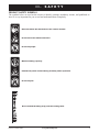
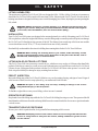
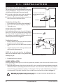
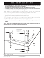
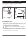
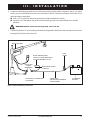
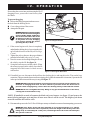
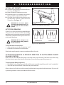
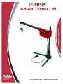
Go-Go Travel Lift
SAFETY
GUIDELINES
An authorised Pride Provider or qualified technician must perform the initial setup of this
product and must perform all of the procedures in this manual.
The symbols below are used throughout this owner's manual and on the Go-Go Travel Lift to identify warnings and important information. It is very important for you to read them and understand them completely.
WARNING! Indicates a potentially hazardous condition/situation. Failure to follow
designated procedures can cause either personal injury, component damage, or
malfunction. On the product, this icon is represented as a black symbol on a yellow triangle
with a black border.
MANDATORY! These actions should be performed as specified. Failure to perform
mandatory actions can cause personal injury and/or equipment damage. On the product,
this icon is represented as a white symbol on a blue dot with a white border.
PROHIBITED! These actions are prohibited. These actions should not be performed at
any time or in any circumstances. Performing a prohibited action can cause personal
injury and/or equipment damage. On the product, this icon is represented as a black
symbol with a red circle and red slash.
Please fill out the following information for quick reference:
Pride Provider:______________________________________________________________________
Address:___________________________________________________________________________
Phone Number:__________________________
Purchase Date:__________________________
Serial Number:_____________________________
NOTE: This owner’s manual is compiled from the latest specifications and product information available at the time of publication. We reserve the right to make changes as they become necessary. Any
changes to our products may cause slight variations between the illustrations and explanations in this
manual and the product you have purchased. The latest/current version of this manual is available on
our website.
088 609 661
Copyright © 2007
Pride Mobility Products Corp.
INFMANU2803/Rev C/July 2007
C O N T E N T S
I.
INTRODUCTION ........................................................................................................................ 4
II.
SAFETY ......................................................................................................................................... 5
III. INSTALLATION .......................................................................................................................... 8
IV.
OPERATION ............................................................................................................................... 14
V.
TROUBLESHOOTING ............................................................................................................ 16
VI. WARRANTY................................................................................................................................ 17
Go-Go Travel Lift
www.pridemobility.com
3
I.
INTRODUCTION
SAFETY
WELCOME to Pride Mobility Products Corporation (Pride). The product you have purchased combines state-of
the-art components with safety, comfort, and styling in mind. We are confident that these design features will
provide you with the conveniences you expect during your daily activities. Understanding how to safely operate
and care for this product should bring you years of trouble free operations and service.
Read and follow all instructions, warnings, and notes in this manual and all other accompanying literature before
attempting to operate this product for the first time. In addition, your safety depends upon you, as well as your
provider, caretaker, or healthcare professional in using good judgement.
If there is any information in this manual which you do not understand, or if you require additional assistance for
setup or operation, please contact your authorized Pride Provider. Failure to follow the instructions, warnings,
and notes in this manual and those located on your Pride product can result in personal injury or product
damage and will void Pride’s product warranty.
PURCHASER’S AGREEMENT
By accepting delivery of this product, you promise that you will not change, alter, or modify this product or remove
or render inoperable or unsafe any guards, shields, or other safety features of this product; fail, refuse, or neglect to
install any retrofit kits from time to time provided by Pride to enhance or preserve the safe use of this product.
SHIPPING AND DELIVERY
Before using your Travel Lift, make sure your delivery is complete as some components may be individually
packaged. If you do not receive a complete delivery, please contact your authorized Pride Provider immediately.
Where damage has occurred during transport, either to the packaging or content, please contact the delivery
company responsible.
INFORMATION EXCHANGE
We want to hear your questions, comments, and suggestions about this manual. We would also like to hear about
the safety and reliability of your new scooter, and about the service you received from your authorized Pride
Provider. Please notify us of any change of address, so we can keep you apprised of important information about
safety, new products, and new options that can increase your ability to use and enjoy your scooter. Please feel free
to contact us at the address below:
USA:
Pride Mobility Products Corporation
Attn: Customer Care Department
182 Susquehanna Ave.
Exeter, PA 18643-2694
[email protected]
1-800-424-8250
Canada:
Pride Mobility Products Company
380 Vansickle Road Unit 350
St. Catharines, Ontario L2R 6P7
1-888-570-1113
NOTE: If you ever lose or misplace your product registration card or your copy of this manual, contact
us and we will be glad to send you a new one immediately.
4
www.pridemobility.com
Go-Go Travel Lift
II.
SAFETY
PRODUCT SAFETY SYMBOLS
The symbols below are used on the scooter to identify warnings, mandatory actions, and prohibited actions. It is very important for you to read and understand them completely.
Read and follow the information in the owner’s manual.
Do not lift scooter while seated in it.
Do not lift people.
Maximum lifting capacity.
Pinch/Crush points created during assembly and/or operation.
Do not lift pets.
Do not extend the lifting strap past the warning label.
Go-Go Travel Lift
www.pridemobility.com
5
II.
SAFETY
Avoid exposure to rain, snow, ice, salt, or standing water whenever possible. Maintain
and store in a clean and dry condition.
Only authorized personnel may service this equipment.
Disposal and recycling-Contact your authorized Pride Provider for information on proper
disposal of your Pride product and its packaging.
Disposal and recycling-Contact your authorized Pride Provider for information on proper
disposal of your Pride product and its packaging.
6
www.pridemobility.com
Go-Go Travel Lift
II.
SAFETY
LIFTING CAPABILITIES
The maximum weight the Go-Go Travel Lift was designed to lift is 130 lbs. (60 kg). Under no circumstances
should the Go-Go Travel Lift be made to lift more than 130 lbs. Subjecting the Go-Go Travel Lift to the strain of
hoisting more than it is designed to lift may cause it to fail, damaging your scooter, injuring the person operating the
lift, or both.
WARNING! Adding accessories, oversize batteries, or a different seat will increase the
weight of your scooter. Verify with your authorized Pride Provider that the total weight of
your scooter, after the additions, does not exceed 130 lbs (60 kg ).
INSTALLATION
Your Go-Go Travel Lift system was designed to be mounted primarily in a vehicle. Mounting your Go-Go Travel
Lift on a platform, where the height of the lift may cause the lifting strap to extend beyond a safe point, can damage
the Go-Go Travel Lift and injure the operator of the lift. The distance between the top of the boom arm and the
scooter should not exceed 70 in. (177.8 cm) when the boom arm is fully extended.
Read and fully understand the directions for drilling the mounting holes for the Go-Go Travel Lift base.
WARNING! Before drilling the mounting holes in your vehicle, make absolutely certain,
through a visual inspection, there are no obstructions in the path of the drill bit, such as
the fuel tank, exhaust pipes, or electrical wires.
LIFTING NON-GO-GO TRAVEL LIFT ITEMS
The Go-Go Travel Lift is an extremely versatile device, which users may employ to lift items other than Pride
products. Pride has no control over such use, nor can Pride anticipate every possible use to which a Go-Go Travel
Lift may be put. Lifting non-Pride products with the Go-Go Travel Lift is done at the operator’s own risk, and
Pride accepts no liability for damage or injury resulting from such use.
PRELIFT INSPECTION
Inspect the lifting strap of the Go-Go Travel Lift before every use for twisting, fraying, and signs of wear. If signs of
wear become evident, have the strap replaced by your authorized Pride Provider.
WARNING! A frayed or worn lifting strap can snap, resulting in damage to the scooter
being lifted and injury to the lift operator.
To find the weight of the scooter you are lifting, refer to its owner’s manual.
OPERATOR POSITIONING
Keep hands clear of the lifting strap while the Go-Go Travel Lift is lifting/lowering a scooter. The operator of the lift
should stand a safe distance from the unit being lifted/lowered to ensure that his/her feet are never positioned under
a raised scooter.
TRANSPORT VEHICLE POSITIONING
Be sure your vehicle is parked on flat, level ground before attempting to lift a scooter.
WARNING! Attempting to lift a scooter when a vehicle is not on level ground will cause the
scooter to swing toward or away from the vehicle, making it difficult to get the scooter
into the vehicle.
Go-Go Travel Lift
www.pridemobility.com
7
III.
INSTALLATION
The Go-Go Travel Lift can be installed in either side
of your vehicle. The illustrations demonstrate installation on the right side.
BASE EXTENSIONS
L-BASE
PROHIBITED! Avoid exposure to
rain, snow, ice, salt, or standing
water whenever possible. Maintain
and store in a clean and dr y
condition.
NOTE: Most roads have a crown to help with
water runoff. However, if the crown is severe
enough, it may cause difficulty getting your
scooter into the vehicle. In this case it may be
better to install the lift on the left side.
BOLT
38 MM (1.5”)
!
!
NUT
Figure 1. L-Base Extensions
DETERMINE L-BASE LOCATION
1. Assemble the L-Base. See figure 1. For optimal use, insert the base extensions into the Lbase at their farthest extension point and install
the hardware (nuts and bolts). The base extensions can be adjusted to accommodate obstructions.
NOTE: Always insert the bolt from the inside of
the L-base. This allows the base extensions to
be properly tightened without rattling.
2. Before permanently installing the lift, place the Lbase inside your vehicle in the area in which you
intend to install it. See figure 2 for L-base positioning in vehicles with hatchbacks, or figure 3
for trunk installation.
Figure 2. L-Base (Hatchback Installation)
WHEEL WELL
Positioning the L-base close to the rear allows the
boom-arm to stay as short as possible; this enables
the boom arm to swing freely without making contact
with the vehicle.
VEHICLES WITH TRUNKS
Position the L-base as shown in figure 3. You may
need to situate the L-base so the wheel well doesn’t
interfere with the L-base extensions. Ensure there is
adequate room for a scooter to comfortably fit into
the trunk.
Figure 3. L-Base (Trunk Installation)
8
www.pridemobility.com
Go-Go Travel Lift
III.
INSTALLATION
!
ASSEMBLING THE LIFT
1. Insert the upper post into the L-base. See figure 4.
2. Assemble the split ring collar. See figure 5.
3. Slide the split ring collar over the upper post
and tighten both screws (a good starting point
is approximately 12in. (30 cm). down from the
top of the upper post). See figure 4. To ensure safe operation, the split ring collar must
be secured no closer than 5 in. (12.5 cm) from
the top of the upper post.
!
MINIMUM OF 5” (12.5 CM)
SPLIT RING COLLAR
UPPER POST
WARNING! Failing to tighten both
screws of the split ring collar
could cause damage to your lift,
scooter, and vehicle.
NOTE: The split ring collar may need to be adjusted down so the boom arm has sufficient head
room to swing into a vehicle, or adjusted up so
the scooter being lifted has ample room to clear
obstructions.
L-BASE
Figure 4. Upper Post Installation
1. BRING RING HALVES TOGETHER
4 . Lower the motor housing over the upper post until it
rests on the split ring collar. See figure 6.
WARNING! Pinch/Crush hazard!
Keep hands clear of the upper post
when lowering the motor housing.
WARNING! The lift will be top
heavy until mounted securely. Get
assistance to help stabilize the lift
while swinging the boom arm.
VEHICLES WITH HATCHBACKS - MINI
VANS, STATION WAGONS, ETC.
Once the lift is assembled and seated on the L-base,
close the hatch slowly to make sure the lift doesn’t
make contact with it. If the lift is too close to the rear,
adjust its position slightly until the hatch can close without making contact with the lift. Positioning the Lbase close to the rear allows the boom-arm to stay as
short as possible. This enables the lift to swing into
the vehicle without contacting the far side of the vehicle.
2. INSERT SCREWS AND TIGHTEN
Figure 5. Split Ring Collar Assembly
You may need to adjust the height of the motor housing (see figures 6 and 7) or the length of the boomarm (see figure 8) so the boom arm can swing freely
without hitting at any point inside the vehicle.
Figure 6. Motor Housing Installation
Go-Go Travel Lift
www.pridemobility.com
9
III.
INSTALLATION
SECURE NO CLOSER THAN 5”
(12.5 CM) FROM THE TOP OF
THE POST.
!
SPLIT RING COLLAR ADJUSTMENT
The split ring collar is the height adjustment for the motor
housing. See figure 7. The placement of the split ring
collar determines the height of the motor housing.
" Lower the collar when more room is needed overhead to swing the boom arm inside a vehicle.
" Raise the collar when more height is needed to enable a scooter to be lifted into a trunk.
SCREWS
BOOM ARM ADJUSTMENT
Before adjusting the boom arm, lower the lifting hook
about 12 in. (30 cm). This will provide enough slack in
the strap to enable the adjustable portion of the boom
arm (top tube) to be pulled out of the bottom tube to its
farthest adjustment hole. See figure 8.
!
To adjust the split ring collar:
1. Loosen the two screws on the collar. See figure 7.
2. Raise or lower the collar to the height you may need.
3. Tighten the screws
Figure 7. Split Ring Collar
BOW TIE COTTER PIN
TOP TUBE
ADJUSTMENT HOLES
To adjust the boom arm:
1. Remove the bow tie cotter pin from the adjustment
pin and remove the adjustment pin.
2. Slide the top tube in or out to the desired adjustment
hole.
3. Align the adjustment holes of the top and bottom tube
and reinsert the adjustment pin.
BOTTOM TUBE
LIFTING
HOOK
ADJUSTMENT PIN
NOTE: Do not force the pin into the adjustment
hole. Be sure that the strap is not pinched when
Figure 8. Boom Arm Adjustment
inserting the pin.
4. Reinstall the bow tie cotter pin.
L-BASE INSTALLATION
After determining the ideal spot for your lift to be permanently mounted, remove the entire lift from the vehicle
except for the L-base.
1. Inspect the undercarriage of the vehicle where the lift L-base is located for obstructions that may hinder the
installation of the five (5) mounting bolts that will secure the L-base to the vehicle. Obstructions may consist of
electrical wiring, gas tank, bumper mounts, or exhaust pipes. You may need to adjust the base extensions to
clear obstructions. If possible, install the L-base with the base extensions fully extended. See figure 9.
WARNING! The bumper mounts on some vehicles are gas pressured. DO NOT drill into
them. They may explode casing severe injury.
10
www.pridemobility.com
Go-Go Travel Lift
III.
INSTALLATION
2. If all is clear under the L-base, mark the position of the five (5) mounting holes and drill them using a 3/8-in. drill
bit. Drill all mounting holes from inside the vehicle. See figure 9.
3. Reinstall the L-base and align the mounting holes of the L-base with the holes you just drilled.
4. Position the T-bar on the end of the base support that runs parallel with the rear of the vehicle, and install a
mounting bolt and washer through it and the L-base. See figure 9.
NOTE: The T-bar need only be installed in van or SUV installations. When the lift is installed inside
a trunk, it is necessary to remove the motor housing and upper post for the trunk to close.
5. Install the four (4) remaining mounting bolts and washers onto the L-base.
NOTE: Choosing the correct length bolt allows enough bolt-thread to pass through the undercarriage,
ensuring enough room for the mounting washer and nut to be installed securely.
6. From under the vehicle, install the mounting washers and nuts to all five (5) mounting bolts and tighten. See
figure 9.
NOTE: The two holes in the mounting washers are for working around obstructions. Choose the hole
that best works in the area you are installing the mounting bolts.
MOUNTING BOLTS
50 MM (2”) OR
75 MM (3”)
T-BAR
WASHER
MOUNTING HOLE
MOUNTING WASHER
NUT
Figure 9. Securing The L-Base
Go-Go Travel Lift
www.pridemobility.com
11
III.
INSTALLATION
7. Place the L-base cap over the L-base and secure it with the supplied screws. See figure 10.
8. Reinstall the upper post.
9. Reinstall the motor housing and make adjustments as necessary.
The lift is now fully assembled. See figure 11.
PHILLIPS HEAD SCREW
10 MM
L-BASE CAP
MOTOR HOUSING
UPPER POST
L-BASE CAP
L-BASE
T-BAR
Figure 10. L-Base Cap
Figure 11. Fully Assembled Lift
ELECTRICAL WIRING INSTALLATION
1. Route the lift’s long red positive (+) power wire (starting at the lift) through the interior of the vehicle until you
reach the automobile battery. See figure 12. Conceal the wire behind or under the interior panels (there
should be existing holes). Be certain that the wire is protected with a rubber grommet when passing it through
the metal panels and into the engine compartment. Inside the engine compartment, secure the wire to the
firewall and the inner fender with the supplied plastic wire ties. Use care not to cause abrasions to the power
wire. It is important to secure the power wire at various points along its run.
WARNING! The red positive (+) wire must be connected directly to the positive (+) battery
terminal.
2. Connect the short portion (with fuse) of the red positive (+) power wire to the positive (+) battery terminal.
3. Insert the end of the long portion of the red power wire into the yellow connector of the short portion and crimp
it securely. Once crimped, pull on the wire gently to ensure a good connection. Wrapping the connector with
electrical tape will help prevent moisture from corroding the connection.
12
www.pridemobility.com
Go-Go Travel Lift
III.
INSTALLATION
4. Connect the short black (ground) wire to a clean, bare metal area of the vehicle using the 12 mm (1/2 in.) sheet
metal screw provided. Mount to an area close to the base of the lift. This allows adequate slack in the wire to
make the harness connections.
" Drill a 1/16-in. pilot hole where the ground wire will be attached to the vehicle.
" Insert the screw through the ring at the end of the black (ground) wire and install the screw into the
pilot hole.
WARNING! DO NOT attach the black (ground) wire to the lift.
5. Connect the harness of wires leading to the battery and ground to the harness that extends from the motor
housing (black to black and red to red).
MOTOR HOUSING
BLACK (GROUND) WIRE
ATTACH TO CLEAN, BARE METAL
IN CLOSE PROXIMITY TO LIFT
BLACK - RED
POWER
HARNESSES
FUSE
25-AMP
SHEET METAL SCREW
12 MM (1/2”)
ROUTE RED (+) POWER WIRE
TO BATTERY
CONNECTOR
(USE PLIERS OR CRIMPING
TOOL TO CRIMP)
AUTOMOBILE
BATTERY
Figure 12. Electrical Wiring Connections
Go-Go Travel Lift
www.pridemobility.com
13
I V.
OPERATION
LIFTING THE SCOOTER
WARNING! Before operating the
Go-Go Travel Lift for the first time,
be absolutely sure you have the
proper docking device for your
scooter.
1. Position your scooter (with the key removed and
the tiller lowered) on the ground behind the installed lift. Be sure that there is ample space between the scooter and the vehicle bumper to ensure that the scooter will not hit the bumper while
being raised. If the scooter is too far from the
vehicle’s bumper, the scooter will be dragged
when attempting to lift it.
2. Position the boom arm over the scooter.
3. Operate the lift (use the hand control—see figure 13) in the downward direction until the lifting hook reaches the T-bar. The lift strap should
drop straight down to the T-bar. See figure 14.
PRESS TO OPERATE LIFT IN PRESS TO OPERATE LIFT
A DOWNWARD DIRECTION IN AN UPWARD DIRECTION
DOWN UP
Figure 13. Hand Control
DOCKING DEVICE T-BAR
WARNING! Inspect the lifting strap
before each use for twisting,
fraying, and signs of wear.
" Keep tension on the lifting strap with your
free hand when lowering the lifting hook.
" Lower the lifting hook only to the T-bar of
the docking device.
WARNING! Do not extend the
lifting strap past the warning label
located on it. See figure 15.
LIFTING HOOK
Figure 14. Lifting Hook Placement
4. Place the lifting hook onto the docking device Tbar. See figure 14.
5. Operate the lift in the upward direction.
WARNING! Pinch/Crush Hazard!
Always keep hands clear of the
lifting strap while the SilverBoom
is lifting/lowering a mobility
device. The operator of the lift
should stand a safe distance away
from the mobility device being
lifted/lowered to ensure that feet
are never positioned under a raised
mobility device.
Figure 15. Lifting Strap Warning Label
14
www.pridemobility.com
Go-Go Travel Lift
I V.
OPERATION
Do not drag the scooter into position using the lift. If
dragging occurs, your scooter is too far away from
the vehicle.
To prevent dragging:
" Release the lifting strap tension then remove
the hook from the docking device.
" Correct the position of the scooter.
" Attempt the lift again.
MANDATORY! The maximum weight
the Go-Go Travel Lift was designed
to lift is 130 lbs. (60 kg). Subjecting
the Go-Go Travel Lift to the strain
of lifting more than it is designed
to may cause it to fail, damaging
your scooter, injuring the person
operating the lift, or both.
6. If the scooter begins to tilt, lower it completely
and adjust the docking device by moving the pickup bar in the direction of the tilt (when using a
C-arm).
7. Tighten the pick-up bar once the proper balance
point has been found (when using a C-arm).
8. Once the scooter is raised high enough to fit into
the vehicle, stop the lift. See figure 16.
9. Swing the boom arm toward the vehicle. When
the scooter is securely in the vehicle, lower the lift
strap until all of the scooter’s wheels are on a
solid surface.
Figure 16. Lifting The Scooter
Figure 17. Securing The Boom Arm
10. If installed in a van, disconnect the hook from the docking device and attach it to the T-bar on the base
extension. (This prevents the boom arm from swinging freely while the automobile is in motion.) Operate the lift
in the upward direction until the strap is snug. See figure 17.
WARNING! When transporting the lift, secure the boom arm to prevent it from rotating in any
direction. A swinging boom arm can be a hazard. If you can’t secure the boom arm to
prevent it from swinging freely, remove the motor housing and lay it flat inside the vehicle.
WARNING! Do not overtighten the strap. Doing so may put unwanted strain on the motor,
causing the circuit breaker to trip.
NOTE: If installed in a trunk, disconnect the black-red power harness (see figure 12) and remove the
motor housing and upper post and place it in an area where it will be secure. The height of the boom
arm will not allow the trunk to close.
11. Disconnect the power to the Go-Go Travel Lift to prevent any accidental movement when transporting your scooter.
WARNING! Your Go-Go Travel Lift was designed to be mounted primarily in a vehicle.
Mounting your Go-Go Travel Lift on a platform, where the height of the lift may cause the
lifting strap to extend beyond a safe point, can damage the Go-Go Travel Lift and injure
the operator of the lift.
Go-Go Travel Lift
www.pridemobility.com
15
V.
TROUBLESHOOTING
LIFT WILL NOT OPERATE
" Check the circuit breaker reset button. Reset if
necessary. See figure 18.
" Ensure all harness connections are secure.
" Ensure the power wire leading to the positive
battery terminal is tight and not corroded.
" Check the fuse located on the red power wire
near the battery. If blown, replace with a new
25-amp fuse. See figure 19.
WARNING! Do not use a higher
rated fuse than 25-amp. Doing so
may damage the lift’s electrical
system.
CIRCUIT BREAKER RESET
BUTTON
Figure 18. Circuit Breaker Reset Button
LIFT STOPS OPERATING
If your Go-Go Travel Lift is heavily strained because
of excessive loads, the main circuit breaker (see figure 18) may trip to protect the motor and electronics
from damage. When the breaker trips, the entire electrical system shuts down.
WARNING! Never attempt to lift
more than 130 lbs. (60 kg) with the
Go-Go Travel Lift.
WORKING FUSE
BLOWN FUSE
Figure 19. Fuse Replacement
To reset the main circuit breaker:
1. Allow a minute or so for the electronics to “cool.”
2. Push in the reset button to reset the breaker.
If the breaker trips frequently, contact your authorized Pride Provider.
LIFTING STRAP TRAVELS IN OPPOSITE DIRECTION OF BUTTON BEING PUSHED
ON HAND CONTROL
Before each use, check that the lifting strap is traveling in the proper direction. If the belt travels in the wrong
direction when you press either the up or down button, you must restore proper lifting strap travel.
To restore proper lifting strap travel:
1. Pull slightly on the strap and operate the lift until the strap is extended completely past the “stop” warning label.
2. Allow the strap to rewind itself. Do not allow any twists in the belt.
Observe the travel of the belt: it should correspond with the button being pushed on the hand control. If you are still
experiencing problems, contact your authorized Pride Provider.
16
www.pridemobility.com
Go-Go Travel Lift
VI.
WARRANTY
ONE YEAR LIMITED WARRANTY
For one year from the date of purchase, Pride Mobility Products Corporation will repair or replace at our option
to the original purchaser, free of charge, any of the following parts found upon examination by an authorized
representative of Pride Mobility Products Corporation to be defective in material and/or workmanship:
" Main frame
" Electronic switch assemblies
" Motor/gearbox assembly
Warranty service can be performed by an authorized Pride Provider or by Pride Mobility Products Corporation.
Do not return faulty parts to Pride Mobility Products Corporation without prior consent. All transportation costs
and shipping damage incurred while submitting parts for repair or replacement are the responsibility of the original
purchaser.
WARRANTY EXCLUSIONS
Damage caused by:
" Abuse, misuse, accident, or negligence.
" Improper operation, installation, maintenance, or storage.
" Commercial use or other than intended use.
" Repairs and/or modifications made to any part without specific consent from Pride
Mobility Products Corporation.
" Circumstances beyond the control of Pride.
Labor, service calls, shipping, and other charges incurred for repair of the product unless specifically authorized by Pride.
There is no other express warranty.
Implied warranties, including those of merchantability and fitness for a particular purpose, are limited to one year
from the date of purchase and to the extent permitted by law. Any and all implied warranties are excluded. This is
the exclusive remedy. Liabilities for consequential damages under all warranties are excluded. Some states do not
allow limitations on how long an implied warranty lasts or do not allow the exclusion of limitation of incidental or
consequential damages, so the above limitation or exclusion may not apply to you. This warranty gives you specific
rights and you may also have other rights, which vary from state to state.
Please fill out and return the warranty card to Pride. This will aid Pride in providing the best possible technical and
customer service.
Go-Go Travel Lift
www.pridemobility.com
17
NOTES
18
www.pridemobility.com
Go-Go Travel Lift
*INFMANU2803*