1
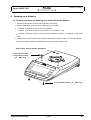
Series 360 EP / ES
Service manual
Service-Anleitung
SERVICE
MANUAL
SERIES 360 EP
SERIES 360 ES
Order no.
350-8135
Index -
Service manual cpl.
Service-Anleitung kpl.
350-7906
Index -
Content
Inhalt
Technische Änderungen vorbehalten
Subject to technical modification
Copyright
These service instructions are protected by copyright. All rights reserved. No part of the service instructions may be reproduced,
processed, duplicated or published in any form by photocopying, microfilming, reprinting or other process, in particular electronic
means, without the written agreement of Precisa Gravimetrics AG.
Diese Service-Anleitung ist urheberrechtlich geschützt. Alle Rechte vorbehalten. Kein Teil der Serviceanleitung darf ohne schriftliche Genehmigung der Precisa Gravimetrics AG in irgendeiner Form durch Fotokopien, Mikrofilm, Nachdruck oder andere Verfahren, insbesondere auch elektronischer Art, reproduziert, verarbeitet, vervielfältigt oder verbreitet werden.
© Precisa Gravimetrics AG, 8953 Dietikon, Switzerland, 2009.
Precisa Gravimetrics AG
Moosmattstrasse 32
Box 352
CH-8953 Dietikon
Contents
Inhaltsverzeichnis
Series 360 EP / ES
Contents / Inhaltsverzeichnis
SERVICE
MANUAL
SERIES 360 EP
SERIES 360 ES
Section A: Mechanics / Kapitel A: Mechanik - - - - - - - - A1
1.
2.
How to order spare parts / Anleitung zur Bestellung von Ersatzteilen .......... A2
Bottom of balance / Gehäuse Unterteil ............................................................. A4
2.1
2.2
2.3
Measuring resistor A2 / Messwiderstand A2................................................................... A5
Measuring resistor A3 / Messwiderstand A3.................................................................... A5
Measuring resistor M, C, D / Messwiderstand M, C, D .................................................... A5
3.
Top of balance / Gehäuse Oberteil .................................................................... A6
3.1
3.2
Labels Series 360 EP ...................................................................................................... A7
Labels Series 360 ES ...................................................................................................... A7
4.
Weighing cell / Wägezelle ................................................................................... A8
4.1
4.2
4.3
4.4
4.5
4.6
4.7
4.8
4.9
4.10
Group A2 / Gruppe A2 ..................................................................................................... A9
Group A3 / Gruppe A3 ................................................................................................... A10
Group M1 / Gruppe M1 .................................................................................................. A11
Group M2 / Gruppe M2 .................................................................................................. A12
Group C2 / Gruppe C2 ................................................................................................... A13
Group C3 / Gruppe C3 ................................................................................................... A14
Group D1 / Gruppe D1 ................................................................................................... A15
Group D2 / Gruppe D2 ................................................................................................... A16
Overview of flexure sheet repair set / Übersicht der Reparatur-Lagersets .................... A17
Overview of flexure sheets / Übersicht der Biegelager .................................................. A18
5.
6.
Weighing pan Group A / Waagschale Gruppe A ............................................ A19
Weighing pan 135 Group M / Waagschale 135 Gruppe M.............................. A20
6.1
6.2
Group / Gruppe M1 ........................................................................................................ A21
Group / Gruppe M2 ........................................................................................................ A21
7.
8.
9.
10.
11.
12.
Weighing pan 200 Group C,D / Waagschale 200 Gruppe C,D ....................... A22
Windshield EP / Windschutz EP 350-8657 ...................................................... A23
Windshield ES / Windschutz ES 350-8659 ...................................................... A25
Windshield XT / Windschutz XT 350-8517....................................................... A27
Windshield standard M / Windschutz standard M.......................................... A29
Calibration weights for 320-7140 / Kalibriergewichte für 320-7140 .............. A30
12.1 Group / Gruppe A2,A3 ................................................................................................... A30
12.2 Group / Gruppe M1 ........................................................................................................ A30
12.3 Group / Gruppe M2,C2,C3,D1,D2.................................................................................. A30
13. Power supply / Netzadapter.............................................................................. A31
Precisa Gravimetrics AG
Index -
i1
Contents
Inhaltsverzeichnis
Series 360 EP / ES
Section B: Electronics / Kapitel B: Elektronik - - - - - - - B1
1.
Main board / Hauptprint 360-7200-020............................................................... B2
1.1
1.2
Exchange of the main board 360-7200-020..................................................................... B2
Austauschen des Hauptprintes 360-7200-020................................................................. B2
2.
Connector board / Steckerprint 360-7201-010 .................................................. B3
2.1
Assembly / Bestückung 360-7201-010 ............................................................................ B3
Section C: Service - - - - - - - - - - - - - - - - - - - - - - - - - - - - C1
1.
Service tools and equipment.............................................................................. C2
1.1
1.2
Tool set (350-8537).......................................................................................................... C2
Equipment ........................................................................................................................ C3
2.
Opening up a balance ......................................................................................... C4
2.1
General procedure for opening up a Series 360 series balance...................................... C4
3.
Introduction / Preparation of the tools .............................................................. C5
3.1
3.2
Introduction ...................................................................................................................... C5
Preparation of the tools .................................................................................................... C5
4.
Dismantling the weighing cell ............................................................................ C6
4.1
4.2
4.3
4.4
4.5
4.6
4.7
Removing the top of balance ........................................................................................... C6
Removing the weighing cell from the bottom of balance.................................................. C6
Removing the flexure-strap .............................................................................................. C7
Removing the two flexure holders.................................................................................... C7
Removing the coil............................................................................................................. C7
Removing the support piece ............................................................................................ C7
Removing the balance arm .............................................................................................. C7
5.
Installing the new „H-flexure sheets“................................................................ C9
5.1
5.2
Removing the old „H-flexure sheets“................................................................................ C9
Installing the new „H-flexure sheets“................................................................................ C9
6.
Cleaning ............................................................................................................. C10
6.1
6.2
6.3
Cleaning the pot ............................................................................................................. C10
Cleaning the coil ............................................................................................................ C10
Final check of cleaning................................................................................................... C10
7.
Assembling the weighing cell .......................................................................... C11
7.1
7.2
7.3
7.4
7.5
7.6
7.7
7.8
7.9
Assembling the balance arm.......................................................................................... C11
Assembling the coil, the magnet cover and the transport safety device ........................ C11
Assembling the sensor mechanism and the stopper ..................................................... C12
Assembling new “V-flexure sheets“................................................................................ C12
Assembling the support piece and inner cone ............................................................... C13
Assembling the flexure holders ...................................................................................... C13
Assembling the new „flexure-strap“................................................................................ C14
Dismantling the assembly jigs........................................................................................ C15
Installing the weighing cell in the bottom of balance ...................................................... C15
Section D: Adjustments - - - - - - - - - - - - - - - - - - - - - - - - D1
1.
Adjustments......................................................................................................... D2
1.1
1.2
Activation of the service mode ES and EP....................................................................... D2
Set the open balance to the service mode ES or EP ....................................................... D2
Precisa Gravimetrics AG
Index -
i2
Contents
Inhaltsverzeichnis
Series 360 EP / ES
1.3
1.4
1.5
1.6
1.7
1.8
1.9
1.10
1.11
1.12
1.13
Adjusting of the symmetry ES and EP ............................................................................. D3
Checking the pre-load ES and EP ................................................................................... D3
Checking the lowering process of the calibration weight ES............................................ D3
Checking the lowering process of the calibration weight EP............................................ D4
Adjusting the corner load ................................................................................................. D4
Final check of corner load ................................................................................................ D6
Set the closed balance to the service mode ES or EP..................................................... D6
Linearisation of the balance ............................................................................................. D7
Adjustment of the internal calibration weight.................................................................... D7
Final check of the adjustment .......................................................................................... D7
S-correction of a balance ................................................................................................. D8
2.
3.
Final check ........................................................................................................... H9
Error messages ................................................................................................. H10
3.1
3.2
3.3
Operating error............................................................................................................... H10
Fatal error ...................................................................................................................... H10
Hardware error ............................................................................................................... H11
4.
Discussion with the manufacturer................................................................... H12
Precisa Gravimetrics AG
Index -
i3
Section A: Mechanics / Kapitel A:
Mechanik
Series 360 EP / ES
Section A: Mechanics /
Kapitel A: Mechanik
Precisa Gravimetrics AG
Index -
A1
How to order spare parts / Anleitung zur
Bestellung von Ersatzteilen
Series 360 EP / ES
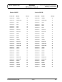
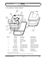
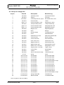
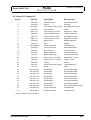
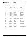
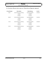
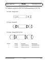
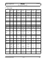
1. How to order spare parts / Anleitung zur Bestellung von Ersatzteilen
In order to faciliate the searching of spare parts, this chapter is reorganized in groups.
The following chart shows, to which group the balance belongs, regarding the series number, the order
number and the model type.
Example:
Series 360EP
Order No. 360-9235
Model 420A-FR
Group A3
On all subordinated representations, the desired spare part is to find in group A3
Um die Suche nach dem gewünschten Ersatzteil zu erleichtern, wurde dieses Kapitel in Gruppen zusammengefasst.Die nachfolgende Tabelle zeigt auf, zu welcher Gruppe die Waage anhand der Serie-,
der Bestellnummer und des Modelles zuzuordnen ist.
Beispiel :
Serie 360EP
Bestell-Nr. 360-9235
Modell 420A-FR
Gruppe A3
In allen folgenden Darstellungen ist das gewünschte Ersatzteil unter der Gruppe A3 zu finden
Precisa Gravimetrics AG
Index -
A2
How to order spare parts / Anleitung zur
Bestellung von Ersatzteilen
Series 360 EP / ES
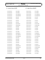
Series 360 ES
Series 360 EP
Order-No.
Model
Group
Order-No.
Model
Group
360-9100
125SM
A2
360-9102
125SM
A2
360-9101
225SM-DR
A2
360-9103
225SM-DR
A2
360-9231
120A
A2
360-9237
120A
A2
360-9232
220A
A2
360-9238
220A
A2
360-9233
320A
A3
360-9239
320A
A3
360-9234
420A
A3
360-9240
420A
A3
360-9235
420A-FR
A3
360-9241
420A-FR
A3
360-9236
620A-DR
A3
360-9242
620A-DR
A3
360-9345
320M
M1
360-9352
320M
M1
360-9346
620M
M1
360-9353
620M
M1
360-9347
920M
M2
360-9354
920M
M2
360-9348
1220M
M2
360-9355
1220M
M2
360-9349
620M-FR
M1
360-9356
620M-FR
M1
360-9350
1220M-FR
M2
360-9357
1220M-FR
M2
360-9351
3220M-DR
M2
360-9358
3220M-DR
M2
360-9437
1200C
C2
360-9444
1200C
C2
360-9438
2200C
C2
360-9445
2200C
C2
360-9439
4200C
C3
360-9446
4200C
C3
360-9440
6200C
C3
360-9447
6200C
C3
360-9441
8200C
C3
360-9448
8200C
C3
360-9442
6200C-FR
C3
360-9449
6200C-FR
C3
360-9443
8200C-DR
C3
360-9450
8200C-DR
C3
360-9534
6200D
D1
360-9537
6200D
D1
360-9535
8200D
D2
360-9538
8200D
D2
360-9536
12200D
D2
360-9539
12200D
D2
360-9613
12200G
D2
360-9614
12200G
D2
Precisa Gravimetrics AG
Index -
A3
Bottom of balance / Gehäuse Unterteil
Series 360 EP / ES
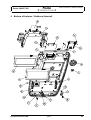
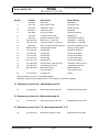
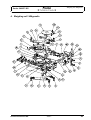
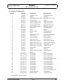
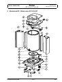
2. Bottom of balance / Gehäuse Unterteil
Precisa Gravimetrics AG
Index -
A4
Bottom of balance / Gehäuse Unterteil
Series 360 EP / ES
Key-No.
Part-No.
Description
Bezeichnung
1
320-3069
Blind plug
Blindzapfen
2
320-7139
Servo-motor compl.
Servomotor kpl.
3
320-7140
Calibration compl.
Kalibrierung kpl.
4
360-2002 *
Calibration plate
Eichplatte
5
360-7000
Housing‘s bottom
Gehäuse Unterteil
6
360-7004
Levelling screw compl.
Stellfuss kpl
7
360-7013
Graphic display EP series
Grafikdisplay Serie EP
8
360-7200-020
Main board → page B2
Hauptprint → page B2
9
360-7201-010
Connector board → page B3
Steckerprint → page B3
10
360-8009
Slide-in module standard RS 232
Einschub Standard RS 232
11
MW 2075-003
Sealing lenght 85mm
Dichtung Länge 85mm
12
PN 1100-041
Screw M4x5
ZS-Schraube M4x5
13
PN 1100-061
Screw M3x6
ZK-Schraube M3x6
14
PN 1100-062
Screw M3x8
ZK-Schraube M3x8
15
PN 1100-170
Screw M4x8
ZL-Schraube M4x8
16
PN 1100-176 **
Screw M4x12
ZS-Schraube M4x12
17
PN 1500-098
Spring washer 10x5.2x0.25 Cr
Tellerfeder 10x5.2x0.25 Cr
18
PN 3260-027
LCD Display ES series
LCD Display Serie ES
19
PN 3329-XXX
Measuring resistor
see chart below
Messwiderstand
siehe Tabelle unten
20
PN 3730-004
Levelling unit
Libelle
* Approved balances only / nur eichfähige Waagen
**Analytical- and Semi-micro balances only / nur Analyse- und Semimicrowaagen
2.1 Measuring resistor A2 / Messwiderstand A2
19
PN 3329-032
Measuring resistor 250 Ohm
Messwiderstand 250 Ohm
2.2 Measuring resistor A3 / Messwiderstand A3
19
PN 3329-031
Measuring resistor 150 Ohm
Messwiderstand 150 Ohm
2.3 Measuring resistor M, C, D / Messwiderstand M, C, D
19
PN 3329-028
Precisa Gravimetrics AG
Measuring resistor 51 Ohm
Index -
Messwiderstand 51 Ohm
A5
Top of balance / Gehäuse Oberteil
Series 360 EP / ES
3. Top of balance / Gehäuse Oberteil
Key-No.
Part-No.
Description
Bezeichnung
1
360-4000
Keypad EP
Folientastatur EP
2
360-4001
Keypad ES
Folientastatur ES
3
350-8676 *
350-8663 *
Dustcover A/SM
Dustcover M/C/D
Staubschutz A/SM
Staubschutz M/C/D
4
page A 7
Label
Typenschild
5
360-4008
Glass
Displayglas
6
360-7011
360-7017
Top of balance M/C/D
Top of balance A/SM
Gehäuse Oberteil M/C/D
Gehäuse Oberteil A/SM
7
MW 2075-003 **
Sealing lenght 1055mm
Dichtung Länge 1055mm
8
MW 2075-003 **
Sealing lenght 215mm
Dichtung Länge 215mm
9
PN 1053-012
Blind plug
Abdeckkappe
10
PN 1053-014 **
Blind plug
Schutzstopfen
11
PN 1100-227
Screw M4x25
ZK-Schraube M4x25
* set of 20 pieces / Set mit 20 Stück
**Analytical- and Semi-micro balances only / nur Analyse- und Semimicrowaagen
Precisa Gravimetrics AG
Index -
A6
Top of balance / Gehäuse Oberteil
Series 360 EP / ES
3.1 Labels Series 360 EP
3.2 Labels Series 360 ES
360-7009-001
EP 125SM
360-7010-001
ES 125SM
360-7009-002
EP 160SM
360-7010-002
ES 160SM
360-7009-003
EP 125SM-FR
360-7010-003
ES 125SM-FR
360-7009-004
EP 225SM-DR
360-7010-004
ES 225SM-DR
360-7009-005
EP 120A
360-7010-005
ES 120A
360-7009-006
EP 220A
360-7010-006
ES 220A
360-7009-007
EP 320A
360-7010-007
ES 320A
360-7009-008
EP 420A
360-7010-008
ES 420A
360-7009-009
EP 420A-FR
360-7010-009
ES 420A-FR
360-7009-010
EP 620A-DR
360-7010-010
ES 620A-DR
360-7009-011
EP 320M
360-7010-011
ES 320M
360-7009-012
EP 620M
360-7010-012
ES 620M
360-7009-013
EP 920M
360-7010-013
ES 920M
360-7009-014
EP 1220M
360-7010-014
ES 1220M
360-7009-015
EP 620M-FR
360-7010-015
ES 620M-FR
360-7009-016
EP 1220M-FR
360-7010-016
ES 1220M-FR
360-7009-017
EP 3220M-DR
360-7010-017
ES 3220M-DR
360-7009-018
EP 1220C
360-7010-018
ES 1220C
360-7009-019
EP 2200C
360-7010-019
ES 2200C
360-7009-020
EP 4200C
360-7010-020
ES 4200C
360-7009-021
EP 6200C
360-7010-021
ES 6200C
360-7009-022
EP 8200C
360-7010-022
ES 8200C
360-7009-023
EP 6200C-FR
360-7010-023
ES 6200C-FR
360-7009-024
EP 8200C-DR
360-7010-024
ES 8200C-DR
360-7009-025
EP 6200D
360-7010-025
ES 6200D
360-7009-026
EP 8200D
360-7010-026
ES 8200D
360-7009-027
EP 12200D
360-7010-027
ES 12200D
360-7009-028
EP 12200G
360-7010-028
ES 1220G
Precisa Gravimetrics AG
Index -
A7
Weighing cell / Wägezelle
Series 360 EP / ES
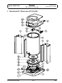
4. Weighing cell / Wägezelle
Precisa Gravimetrics AG
Index -
A8
Weighing cell / Wägezelle
Series 360 EP / ES
4.1 Group A2 / Gruppe A2
Key-No.
Part-No.
Description
Bezeichnung
1
240-4048
Symmetry screw
Symmetrieschraube
2
280-2003
Stopper
Anschlag
3
350-8325 *
Connecting wire set; 10pcs
Bronzeband Set; 10stk
4
320-2004
Flexure holder
Lenker
5
page A 17
Flexure strap Be 1.2mm
Zugband Be 1.2mm
6
320-2032
Transport safety device
Transportsicherung
7
page A 17
Flexure sheet Be 2mm
Hängelager Be 2mm
8
page A 17
Flexure sheet Be 3mm
Biegelager Be 3mm
9
320-2048
Magnet cover
Magnettopfdeckel
11
320-3055
Base
Beilage
12
320-3056
Preload weight
Vorlastgewicht XR
13
320-3067
Insert
Gewindebüchse
14
320-3070
Differential set screw
Differential Gewindestift
15
320-3080
Cover air draft
Deckel Luftzug
16
320-3081
Corner load bush
Eckenlastbuchse
17
320-7130
Inner cone round
Innenkonus rund
18
320-7145
Weight holder left compl.
Gewichtslager links kpl.
19
320-7147
Weight holder right compl.
Gewichtslager rechts kpl.
20
360-7036
Balance arm 1:4.5 compl.
Waagbalken 1:4.5 kpl.
21
360-7031
Support piece 1:4.5 compl.
Träger 1:4.5 kpl.
22
360-2001
Cover holder
Deckelträger
23
360-5002
Chassis
Chassis
24
360-7005
Sensor mechanism compl.
Lichtschranke kpl.
25
F2-152
Spring
Feder
26
PN 1100-039
Screw M3x5
ZS-Schraube M3x5
27
PN 1100-040
Screw M3x8
ZS-Schraube M3x8
28
PN 1100-061
Screw M3x6
ZK-Schraube M3x6
29
PN 1100-106
Screw M3x5
SS-Schraube M3x5 kl. Kopf
30
PN 1100-169
Screw M4x6
ZL-Schraube M4x6
31
PN 1100-170
Screw M4x8
ZL-Schraube M4x8
32
PN 1100-171
Screw M4x10
ZL-Schraube M4x10
33
PN 1100-172
Screw M4x12
ZL-Schraube M4x12
34
PN 1100-172
Screw M4x12
ZL-Schraube M4x12
35
PN 1100-266
Screw M3x10
ZS-Schraube M3x10
36
PN 1100-286
Screw M3x10
SS-Schraube M4x6 kl. Kopf
37
PN 1500-075
Spring washer M4
Tellerfeder M4
38
PN 1500-097
Washer M4 Ms
U-Scheibe M4 Ms
* set of 10 pieces / Set mit 10 Stück
Precisa Gravimetrics AG
Index -
A9
Weighing cell / Wägezelle
Series 360 EP / ES
4.2 Group A3 / Gruppe A3
Key-No.
Part-No.
Description
Bezeichnung
1
240-4048
Symmetry screw
Symmetrieschraube
2
280-2003
Stopper
Anschlag
3
350-8325 *
Connecting wire set; 10pcs
Bronzeband Set; 10stk
4
320-2004
Flexure holder
Lenker
5
page A 17
Flexure strap Be 1.2mm
Zugband Be 1.2mm
6
320-2032
Transport safety device
Transportsicherung
7
page A 17
Flexure sheet Be 2mm
Hängelager Be 2mm
8
page A 17
Flexure sheet Be 3mm
Biegelager Be 3mm
9
320-2048
Magnet cover
Magnettopfdeckel
11
320-3055
Base
Beilage
12
320-3056
Preload weight
Vorlastgewicht XR
13
320-3067
Insert
Gewindebüchse
14
320-3070
Differential set screw
Differential Gewindestift
15
320-3080
Cover air draft
Deckel Luftzug
16
320-3081
Corner load bush
Eckenlastbuchse
17
320-7130
Inner cone round
Innenkonus rund
18
320-2076
Weight holder left
Gewichtslager links
19
320-2077
Weight holder right
Gewichtslager rechts
20
360-7038
Balance arm 1:6 compl.
Waagbalken 1:6 kpl.
21
360-7032
Support piece 1:6 compl.
Träger 1:6 kpl.
22
360-2001
Cover holder
Deckelträger
23
360-5002
Chassis
Chassis
24
360-7005
Sensor mechanism compl.
Lichtschranke kpl.
25
F2-152
Spring
Feder
26
PN 1100-039
Screw M3x5
ZS-Schraube M3x5
27
PN 1100-040
Screw M3x8
ZS-Schraube M3x8
28
PN 1100-061
Screw M3x6
ZK-Schraube M3x6
29
PN 1100-106
Screw M3x5
SS-Schraube M3x5 kl. Kopf
30
PN 1100-169
Screw M4x6
ZL-Schraube M4x6
31
PN 1100-170
Screw M4x8
ZL-Schraube M4x8
32
PN 1100-171
Screw M4x10
ZL-Schraube M4x10
33
PN 1100-172
Screw M4x12
ZL-Schraube M4x12
34
PN 1100-171
Screw M4x10
ZL-Schraube M4x10
35
PN 1100-266
Screw M3x10
ZS-Schraube M3x10
36
PN 1100-286
Screw M3x10
SS-Schraube M4x6 kl. Kopf
37
PN 1500-075
Spring washer M4
Tellerfeder M4
38
PN 1500-097
Washer M4 Ms
U-Scheibe M4 Ms
* set of 10 pieces / Set mit 10 Stück
Precisa Gravimetrics AG
Index -
A10
Weighing cell / Wägezelle
Series 360 EP / ES
4.3 Group M1 / Gruppe M1
Key-No.
Part-No.
Description
Bezeichnung
1
240-4048
Symmetry screw
Symmetrieschraube
2
280-2003
Stopper
Anschlag
3
350-8325 *
Connecting wire set; 10pcs
Bronzeband Set; 10stk
4
320-2004
Flexure holder
Lenker
5
page A 17
Flexure strap Th 1.2mm
Zugband Th 1.2mm
6
320-2032
Transport safety device
Transportsicherung
7
page A 17
Flexure sheet Th 3mm
Hängelager Th 3mm
8
page A 17
Flexure sheet Th 3mm
Biegelager Th 3mm
9
320-2048
Magnet cover
Magnettopfdeckel
10
320-3013
Base
Beilage
11
PN 1500-075
Spring washer M4
Tellerfeder M4
14
360-3000
Corner load screw
Eckenlastschraube
17
360-5003
Inner cone 4kt
Innenkonus 4kt
18
320-2076
Weight holder left
Gewichtslager links
19
320-2077
Weight holder right
Gewichtslager rechts
20
360-7038
Balance arm 1:6 compl.
Waagbalken 1:6 kpl.
21
360-7032
Support piece 1:6 compl.
Träger 1:6 kpl.
23
360-5002
Chassis
Chassis
24
360-7005
Sensor mechanism compl.
Lichtschranke kpl.
25
F2-152
Spring
Feder
26
PN 1100-039
Screw M3x5
ZS-Schraube M3x5
27
PN 1100-040
Screw M3x8
ZS-Schraube M3x8
30
PN 1100-169
Screw M4x6
ZL-Schraube M4x6
31
PN 1100-170
Screw M4x8
ZL-Schraube M4x8
32
PN 1100-171
Screw M4x10
ZL-Schraube M4x10
33
PN 1100-172
Screw M4x12
ZL-Schraube M4x12
34
PN 1100-172
Screw M4x12
ZL-Schraube M4x12
36
PN 1100-286
Screw M3x10
SS-Schraube M4x6 kl. Kopf
37
PN 1500-075
Spring washer M4
Tellerfeder M4
38
PN 1500-075
Spring washer M4
Tellerfeder M4
* set of 10 pieces / Set mit 10 Stück
Precisa Gravimetrics AG
Index -
A11
Weighing cell / Wägezelle
Series 360 EP / ES
4.4 Group M2 / Gruppe M2
Key-No.
Part-No.
Description
Bezeichnung
1
240-4048
Symmetry screw
Symmetrieschraube
2
280-2003
Stopper
Anschlag
3
350-8325 *
Connecting wire set; 10pcs
Bronzeband Set; 10stk
4
320-2004
Flexure holder
Lenker
5
page A 17
Flexure strap Th 1.2mm
Zugband Th 1.2mm
6
320-2032
Transport safety device
Transportsicherung
7
page A 17
Flexure sheet Th 3mm
Hängelager Th 3mm
8
page A 17
Flexure sheet Th 3mm
Biegelager Th 3mm
9
320-2048
Magnet cover
Magnettopfdeckel
10
320-3013
Base
Beilage
11
PN 1500-075
Spring washer M4
Tellerfeder M4
14
360-3000
Corner load screw
Eckenlastschraube
17
360-5003
Inner cone 4kt
Innenkonus 4kt
18
320-2076
Weight holder left
Gewichtslager links
19
320-2077
Weight holder right
Gewichtslager rechts
20
360-7040
Balance arm 1:12 compl.
Waagbalken 1:12 kpl.
21
360-7033
Support piece 1:12 compl.
Träger 1:12 kpl.
23
360-5002
Chassis
Chassis
24
360-7005
Sensor mechanism compl.
Lichtschranke kpl.
25
F2-152
Spring
Feder
26
PN 1100-039
Screw M3x5
ZS-Schraube M3x5
27
PN 1100-040
Screw M3x8
ZS-Schraube M3x8
30
PN 1100-169
Screw M4x6
ZL-Schraube M4x6
31
PN 1100-170
Screw M4x8
ZL-Schraube M4x8
32
PN 1100-171
Screw M4x10
ZL-Schraube M4x10
33
PN 1100-172
Screw M4x12
ZL-Schraube M4x12
34
PN 1100-173
Screw M4x16
ZL-Schraube M4x16
36
PN 1100-286
Screw M3x10
SS-Schraube M4x6 kl. Kopf
37
PN 1500-075
Spring washer M4
Tellerfeder M4
38
PN 1500-075
Spring washer M4
Tellerfeder M4
* set of 10 pieces / Set mit 10 Stück
Precisa Gravimetrics AG
Index -
A12
Weighing cell / Wägezelle
Series 360 EP / ES
4.5 Group C2 / Gruppe C2
Key-No.
Part-No.
Description
Bezeichnung
1
240-4048
Symmetry screw
Symmetrieschraube
2
280-2003
Stopper
Anschlag
3
350-8325 *
Connecting wire set; 10pcs
Bronzeband Set; 10stk
4
320-2004
Flexure holder
Lenker
5
page A 17
Flexure strap Th 1.6mm
Zugband Th 1.6mm
6
320-2032
Transport safety device
Transportsicherung
7
page A 17
Flexure sheet Th 3mm
Hängelager Th 3mm
8
page A 17
Flexure sheet Th 3mm
Biegelager Th 3mm
9
320-2048
Magnet cover
Magnettopfdeckel
10
320-3013
Base
Beilage
11
PN 1500-075
Spring washer M4
Tellerfeder M4
14
360-3000
Corner load screw
Eckenlastschraube
17
360-5003
Inner cone 4kt
Innenkonus 4kt
18
320-2076
Weight holder left
Gewichtslager links
19
320-2077
Weight holder right
Gewichtslager rechts
20
360-7039
Balance arm 1:12 compl.
Waagbalken 1:12 kpl.
21
360-7033
Support piece 1:12 compl.
Träger 1:12 kpl.
23
360-5002
Chassis
Chassis
24
360-7005
Sensor mechanism compl.
Lichtschranke kpl.
25
F2-152
Spring
Feder
26
PN 1100-039
Screw M3x5
ZS-Schraube M3x5
27
PN 1100-040
Screw M3x8
ZS-Schraube M3x8
30
PN 1100-169
Screw M4x6
ZL-Schraube M4x6
31
PN 1100-170
Screw M4x8
ZL-Schraube M4x8
32
PN 1100-171
Screw M4x10
ZL-Schraube M4x10
33
PN 1100-172
Screw M4x12
ZL-Schraube M4x12
34
PN 1100-173
Screw M4x16
ZL-Schraube M4x16
36
PN 1100-286
Screw M3x10
SS-Schraube M4x6 kl. Kopf
37
PN 1500-075
Spring washer M4
Tellerfeder M4
38
PN 1500-075
Spring washer M4
Tellerfeder M4
* set of 10 pieces / Set mit 10 Stück
Precisa Gravimetrics AG
Index -
A13
Weighing cell / Wägezelle
Series 360 EP / ES
4.6 Group C3 / Gruppe C3
Key-No.
Part-No.
Description
Bezeichnung
1
240-4048
Symmetry screw
Symmetrieschraube
2
280-2003
Stopper
Anschlag
3
350-8325 *
Connecting wire set; 10pcs
Bronzeband Set; 10stk
4
320-2004
Flexure holder
Lenker
5
page A 17
Flexure strap Th 1.6mm
Zugband Th 1.6mm
6
320-2032
Transport safety device
Transportsicherung
7
page A 17
Flexure sheet Th 3mm
Hängelager Th 3mm
8
page A 17
Flexure sheet Th 6mm
Biegelager Th 6mm
9
320-2048
Magnet cover
Magnettopfdeckel
10
320-3013
Base
Beilage
11
PN 1500-075
Spring washer M4
Tellerfeder M4
14
360-3000
Corner load screw
Eckenlastschraube
17
360-5003
Inner cone 4kt
Innenkonus 4kt
18
320-2076
Weight holder left
Gewichtslager links
19
320-2077
Weight holder right
Gewichtslager rechts
20
360-7041
Balance arm 1:36 compl.
Waagbalken 1:36 kpl.
21
360-7034
Support piece 1:36 compl.
Träger 1:36 kpl.
23
360-5002
Chassis
Chassis
24
360-7005
Sensor mechanism compl.
Lichtschranke kpl.
25
F2-152
Spring
Feder
26
PN 1100-039
Screw M3x5
ZS-Schraube M3x5
27
PN 1100-040
Screw M3x8
ZS-Schraube M3x8
30
PN 1100-169
Screw M4x6
ZL-Schraube M4x6
31
PN 1100-170
Screw M4x8
ZL-Schraube M4x8
32
PN 1100-171
Screw M4x10
ZL-Schraube M4x10
33
PN 1100-172
Screw M4x12
ZL-Schraube M4x12
34
PN 1100-172
Screw M4x12
ZL-Schraube M4x12
36
PN 1100-286
Screw M3x10
SS-Schraube M4x6 kl. Kopf
37
PN 1500-075
Spring washer M4
Tellerfeder M4
38
PN 1500-075
Spring washer M4
Tellerfeder M4
* set of 10 pieces / Set mit 10 Stück
Precisa Gravimetrics AG
Index -
A14
Weighing cell / Wägezelle
Series 360 EP / ES
4.7 Group D1 / Gruppe D1
Key-No.
Part-No.
Description
Bezeichnung
1
240-4048
Symmetry screw
Symmetrieschraube
2
280-2003
Stopper
Anschlag
3
350-8325 *
Connecting wire set; 10pcs
Bronzeband Set; 10stk
4
320-2004
Flexure holder
Lenker
5
page A 17
Flexure strap Th 1.6mm
Zugband Th 1.6mm
6
320-2032
Transport safety device
Transportsicherung
7
page A 17
Flexure sheet Th 6mm
Hängelager Th 6mm
8
page A 17
Flexure sheet Th 6mm
Biegelager Th 6mm
9
320-2048
Magnet cover
Magnettopfdeckel
10
320-3013
Base
Beilage
11
PN 1500-075
Spring washer M4
Tellerfeder M4
14
360-3000
Corner load screw
Eckenlastschraube
17
360-5003
Inner cone 4kt
Innenkonus 4kt
18
320-2076
Weight holder left
Gewichtslager links
19
320-2077
Weight holder right
Gewichtslager rechts
20
360-7041
Balance arm 1:36 compl.
Waagbalken 1:36 kpl.
21
360-7034
Support piece 1:36 compl.
Träger 1:36 kpl.
23
360-5002
Chassis
Chassis
24
360-7005
Sensor mechanism compl.
Lichtschranke kpl.
25
F2-152
Spring
Feder
26
PN 1100-039
Screw M3x5
ZS-Schraube M3x5
27
PN 1100-040
Screw M3x8
ZS-Schraube M3x8
30
PN 1100-169
Screw M4x6
ZL-Schraube M4x6
31
PN 1100-170
Screw M4x8
ZL-Schraube M4x8
32
PN 1100-171
Screw M4x10
ZL-Schraube M4x10
33
PN 1100-172
Screw M4x12
ZL-Schraube M4x12
34
PN 1100-172
Screw M4x12
ZL-Schraube M4x12
36
PN 1100-286
Screw M3x10
SS-Schraube M4x6 kl. Kopf
37
PN 1500-075
Spring washer M4
Tellerfeder M4
38
PN 1500-075
Spring washer M4
Tellerfeder M4
* set of 10 pieces / Set mit 10 Stück
Precisa Gravimetrics AG
Index -
A15
Weighing cell / Wägezelle
Series 360 EP / ES
4.8 Group D2 / Gruppe D2
Key-No.
Part-No.
Description
Bezeichnung
1
240-4048
Symmetry screw
Symmetrieschraube
2
280-2003
Stopper
Anschlag
3
350-8325 *
Connecting wire set; 10pcs
Bronzeband Set; 10stk
4
320-2004
Flexure holder
Lenker
5
page A 17
Flexure strap Th 1.6mm
Zugband Th 1.6mm
6
320-2032
Transport safety device
Transportsicherung
7
page A 17
Flexure sheet Th 6mm
Hängelager Th 6mm
8
page A 17
Flexure sheet Th 6mm
Biegelager Th 6mm
9
320-2048
Magnet cover
Magnettopfdeckel
10
320-3013
Base
Beilage
11
PN 1500-075
Spring washer M4
Tellerfeder M4
14
360-3000
Corner load screw
Eckenlastschraube
17
360-5003
Inner cone 4kt
Innenkonus 4kt
18
320-2076
Weight holder left
Gewichtslager links
19
320-2077
Weight holder right
Gewichtslager rechts
20
360-7042
Balance arm 1:60 compl.
Waagbalken 1:60 kpl.
21
360-7035
Support piece 1:60 compl.
Träger 1:60 kpl.
23
360-5002
Chassis
Chassis
24
360-7005
Sensor mechanism compl.
Lichtschranke kpl.
25
F2-152
Spring
Feder
26
PN 1100-039
Screw M3x5
ZS-Schraube M3x5
27
PN 1100-040
Screw M3x8
ZS-Schraube M3x8
30
PN 1100-169
Screw M4x6
ZL-Schraube M4x6
31
PN 1100-170
Screw M4x8
ZL-Schraube M4x8
32
PN 1100-171
Screw M4x10
ZL-Schraube M4x10
33
PN 1100-172
Screw M4x12
ZL-Schraube M4x12
34
PN 1100-172
Screw M4x12
ZL-Schraube M4x12
36
PN 1100-286
Screw M3x10
SS-Schraube M4x6 kl. Kopf
37
PN 1500-075
Spring washer M4
Tellerfeder M4
38
PN 1500-075
Spring washer M4
Tellerfeder M4
* set of 10 pieces / Set mit 10 Stück
Precisa Gravimetrics AG
Index -
A16
Weighing cell / Wägezelle
Series 360 EP / ES
4.9 Overview of flexure sheet repair set / Übersicht der Reparatur-Lagersets
Group/Gruppe
Description
Bezeichnung
Set-No.
A2/A3
Flexure sheet set containing:
1 x key 5
2 x key 7
8 x key 8
Lagerset beinhaltet:
1 x Pos.5
2 x Pos.7
8 x Pos.8
350-8593
M1/M2
Flexure sheet set containing:
1 x key 5
2 x key 7
8 x key 8
Lagerset beinhaltet:
1 x Pos.5
2 x Pos.7
8 x Pos.8
350-8592
C2/C3
Flexure sheet set containing:
1 x key 5
2 x key 7
8 x key 8
Lagerset beinhaltet:
1 x Pos.5
2 x Pos.7
8 x Pos.8
350-8594
D1/D2
Flexure sheet set containing:
1 x key 5
2 x key 7
8 x key 8
Lagerset beinhaltet:
1 x Pos.5
2 x Pos.7
8 x Pos.8
350-8595
Precisa Gravimetrics AG
Index -
A17
Weighing cell / Wägezelle
Series 360 EP / ES
4.10 Overview of flexure sheets / Übersicht der Biegelager
Group/Gruppe
Key-No.
Description
Bezeichnung
Set-No.
Pcs./Set
A2
3
Flexure strap Be 1.2mm
Zugband Be 1.2mm
350-8539
5
A3
3
Flexure strap Be 1.2mm
Zugband Be 1.2mm
350-8539
5
M1
3
Flexure strap Th 1.2mm
Zugband Th 1.2mm
350-8540
5
M2
3
Flexure strap Th 1.2mm
Zugband Th 1.2mm
350-8540
5
C2
3
Flexure strap Th 1.6mm
Zugband Th 1.6mm
350-8541
5
C3
3
Flexure strap Th 1.6mm
Zugband Th 1.6mm
350-8541
5
D1
3
Flexure strap Th 1.6mm
Zugband Th 1.6mm
350-8541
5
D2
3
Flexure strap Th 1.6mm
Zugband Th 1.6mm
350-8541
5
A2
7
V-Flexure sheet Be 2mm
Hängelager Be 2mm
350-8542
10
A3
7
V-Flexure sheet Be 2mm
Hängelager Be 2mm
350-8542
10
M1
7
V-Flexure sheet Th 3mm
Hängelager Th 3mm
350-8543
10
M2
7
V-Flexure sheet Th 3mm
Hängelager Th 3mm
350-8543
10
C2
7
V-Flexure sheet Th 3mm
Hängelager Th 3mm
350-8543
10
C3
7
V-Flexure sheet Th 3mm
Hängelager Th 3mm
350-8543
10
D1
7
V-Flexure sheet Th 6mm
Hängelager Th 6mm
350-8544
10
D2
7
V-Flexure sheet Th 6mm
Hängelager Th 6mm
350-8544
10
A2
8
H-Flexure sheet Be 3mm
Biegelager Be 3mm
350-8545
20
A3
8
H-Flexure sheet Be 3mm
Biegelager Be 3mm
350-8545
20
M1
8
H-Flexure sheet Th 3mm
Biegelager Th 3mm
350-8546
20
M2
8
H-Flexure sheet Th 3mm
Biegelager Th 3mm
350-8546
20
C2
8
H-Flexure sheet Th 6mm
Biegelager Th 6mm
350-8547
20
C3
8
H-Flexure sheet Th 6mm
Biegelager Th 6mm
350-8547
20
D1
8
H-Flexure sheet Th 6mm
Biegelager Th 6mm
350-8548
20
D2
8
H-Flexure sheet Th 6mm
Biegelager Th 6mm
350-8548
20
Precisa Gravimetrics AG
Index -
A18
Weighing pan Group A / Waagschale
Gruppe A
Series 360 EP / ES
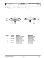
5. Weighing pan Group A / Waagschale Gruppe A
Key-No.
Part-No.
Description
Bezeichnung
1
360-8021
2
360-2036
3
360-8017
4
360-2016
Weighing pan compl. D80
Semimicro balances
Protective ring D80
Semimicro balances
Weighing pan compl. D90
Analytical balances
Protective ring D90
Analytical balances
Waagschale kpl. D80
Semimicro-Waagen
Schutzring D80
Semimicro-Waagen
Waagschale kpl. D90
Analysenwaagen
Schutzring D90
Analysenwaagen
Precisa Gravimetrics AG
Index -
A19
Weighing pan 135 Group M /
Waagschale 135 Gruppe M
Series 360 EP / ES
6. Weighing pan 135 Group M / Waagschale 135 Gruppe M
Precisa Gravimetrics AG
Index -
A20
Weighing pan 135 Group M /
Waagschale 135 Gruppe M
Series 360 EP / ES
6.1 Group / Gruppe M1
Key-No.
Part-No.
Description
Bezeichnung
1
300-4059
Centring disk
Zentrierteller
2
300-4060
Adhesive disk
Kleber für Waagschale
3
320-7014
Weighing pan 135
Waagschale 135
4
320-4047
Centring bolt
Zentrierzapfen
8
320-3038
Adapter
Adapter
5
360-8014
Pan holder compl.
Schalenträger kpl.
6.2 Group / Gruppe M2
Key-No.
Part-No.
Description
Bezeichnung
1
300-4059
Centring disk
Zentrierteller
2
300-4060
Adhesive disk
Kleber für Waagschale
3
320-7014
Weighing pan 135
Waagschale 135
4
320-4047
Centring bolt
Zentrierzapfen
8
320-3038
Adapter
Adapter
5
360-8015
Pan holder compl.
Schalenträger kpl.
Precisa Gravimetrics AG
Index -
A21
Weighing pan 200 Group C,D /
Waagschale 200 Gruppe C,D
Series 360 EP / ES
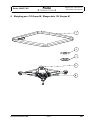
7. Weighing pan 200 Group C,D / Waagschale 200 Gruppe C,D
Key-No.
Part-No.
Description
Bezeichnung
1
300-4059
Centring disk
Zentrierteller
2
300-4060
Adhesive disk
Kleber für Waagschale
3+5
320-7003
Pan holder compl.
Schalenträger kpl.
5
320-4048
Centring bolt
Zentrierzapfen
6
320-7012
Weighing pan 200
Waagschale 200
Precisa Gravimetrics AG
Index -
A22
Windshield EP /
Windschutz EP 350-8657
Series 360 EP / ES
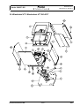
8. Windshield EP / Windschutz EP 350-8657
Precisa Gravimetrics AG
Index -
A23
Windshield EP /
Windschutz EP 350-8657
Series 360 EP / ES
Key-No.
Part-No.
Description
Bezeichnung
1
360-7217-020
Sensor board cpl.
Sensorprint kpl.
2
PN 1100-061
Screw M3x6
ZK-Schraube M3x6
3
360-7216-020
Main board windshield cpl.
Hauptprint Windschutz kpl.
4
PN 1024-003
Lock washer D2,3
Sicherungsscheibe D2,3
5
360-4054
Gear
Kombizahnrad
6
PN 1056-002
Belt
Zahnriemen
7
360-7048
Bottom of windshield EP cpl.
Windschutzboden EP kpl.
8
PN 1100-279
Screw M2x5
ZK-Schraube M2x5
9
360-7050
Driving motor cpl.
Antriebsmotor kpl.
10
360-7045
Windshield profile coated
Windschutzprofil lackiert
11
360-7056
Lip seal right cpl.
Dichtlippe rechts kpl.
12
PN 1100-080
Screw M4x12
ZI-Schraube M4x12
13
360-7047
Holding plate cpl.
Halteblech kpl.
14
360-2014
Slide
Schieber
15
360-4050
Upper cover
Abdeckung oben
16
360-7024
Upper glasses cpl.
Gläser oben kpl.
17
360-4053
Windshield cover
Windschutzdeckel
18
F1-307
Spring
Zugfeder
19
360-7052
Excenter cpl.
Excenter kpl.
20
360-7055
Lip seal left cpl.
Dichtlippe links kpl.
21
360-7046
Glastube cpl.
Glasrohr kpl.
22
360-2029
Inner plate
Einlageblech
23
360-5021
Support
Auflage
24
360-7053
Rotary disc cpl.
Drehteller EP kpl.
25
PN 1100-080
Screw M4x8
ZS-Schraube M4x8
26
360-7218-020
Adapter board cpl.
Adapterprint kpl.
Precisa Gravimetrics AG
Index -
A24
Windshield ES /
Windschutz ES 350-8659
Series 360 EP / ES
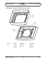
9. Windshield ES / Windschutz ES 350-8659
Precisa Gravimetrics AG
Index -
A25
Windshield ES /
Windschutz ES 350-8659
Series 360 EP / ES
Key-No.
Part-No.
Description
Bezeichnung
1
360-7043
Bottom of windshield ES cpl.
Windschutzboden ES kpl.
2
360-4047
Planet
Planetenzahnrad
3
PN 1024-003
Lock washer D2,3
Sicherungsscheibe D2,3
4
360-7045
Windshield profile coated
Windschutzprofil lackiert
5
360-7056
Lip seal right cpl.
Dichtlippe rechts kpl.
6
360-7046
Glastube cpl.
Glasrohr kpl.
7
PN 1100-080
Screw M4x12
ZI-Schraube M4x12
8
360-7047
Holding plate cpl.
Halteblech kpl.
9
360-2014
Slide
Schieber
10
360-4053
Windshield cover
Windschutzdeckel
11
360-7024
Upper glasses cpl.
Gläser oben kpl.
12
360-4050
Upper cover
Abdeckung oben
13
F1-307
Spring
Zugfeder
14
360-7052
Excenter cpl.
Excenter kpl.
15
360-7055
Lip seal left cpl.
Dichtlippe links kpl.
16
360-2029
Inner plate
Einlageblech
17
360-5021
Support
Auflage
18
360-7054
Rotary disc ES cpl.
Drehteller ES kpl.
19
360-4056
Carrier
Mitnehmer
20
PN 1100-106
Screw M3x5
SS-Schraube M3x5
21
360-7018
Lever cpl.
Hebel kpl.
22
360-4046
Center gear
Hohlrad
23
PN 1100-080
Screw M4x8
ZS-Schraube M4x8
Precisa Gravimetrics AG
Index -
A26
Windshield XT /
Windschutz XT 350-8517
Series 360 EP / ES
10. Windshield XT / Windschutz XT 350-8517
Precisa Gravimetrics AG
Index -
A27
Windshield XT /
Windschutz XT 350-8517
Series 360 EP / ES
Key-No.
Part-No.
Description
Bezeichnung
1
290-2035
Protective ring
Schutzring
2
290-4050
Guide
Führung
3
320-4004
Cover
Abdeckung
4
320-4008
Top panel
Deckel Windschutz
5
320-4012
Front panel
Frontscheibe
6
320-4015
Guide rail right
Gleitführung rechts
7
320-4016
Guide rail left
Gleitführung links
8
320-4017
Sliding ring
Gleitring
9
320-4018
Handle to lever
Griff zu Hebel
10
320-4019
Sliding block
Gleitstück
11
320-4020
Handle
Griff
12
320-4044
Pane fastener
Glashalter
13
320-7010
Side slide right compl.
Glas rechts kpl.
14
320-7028
Side slide left compl.
Glas links kpl.
15
320-7030
Lever left compl.
Hebel links kpl.
16
320-7031
Lever right compl.
Hebel rechts kpl.
17
320-7046
Back panel inside
Rückwand innen
18
320-7047
Back panel outside
Rückwand aussen
19
320-7048
Top slide compl.
Gläser oben kpl.
20
320-7058
Floor plate XT compl.
Bodenblech XT kpl.
21
320-7066
Floor panel
Windschutzboden
22
PN 1100-033
Screw M3x5
SK-Schraube M3x5
23
PN 1100-054
Screw KA30x8
ZK-Schraube KA30x8
24
PN 1100-143
Screw M4x12
ZK-Schraube M4x12
25
PN 1100-170
Screw M4x8
ZL-Schraube M4x8
26
PN 1100-187
Screw M4x12
SK-Schraube M4x12
27
PN 1100-189
Screw M3x5
EK-Schraube M3x5
28
PN 1300-038
Nut
Mutter
Precisa Gravimetrics AG
Index -
A28
Windshield standard M / Windschutz
standard M
Series 360 EP / ES
11. Windshield standard M / Windschutz standard M
Key-No.
Part-No.
Description
Bezeichnung
1
320-7149
Protective ring
Schutzring
2
320-4089
Windshield M
Windschutz M
3
360-3003
Latch
Schnapper
Precisa Gravimetrics AG
Index -
A29
Calibration weights for 320-7140 /
Kalibriergewichte für 320-7140
Series 360 EP / ES
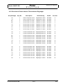
12. Calibration weights for 320-7140 / Kalibriergewichte für 320-7140
12.1 Group / Gruppe A2,A3
12.2 Group / Gruppe M1
12.3 Group / Gruppe M2,C2,C3,D1,D2
Key-No.
Part-No.
Description
Bezeichnung
1
320-3087
Calibration weight 60g
Kalibriergewicht 60g
2
320-3088
Calibration weight 100g
Kalibriergewicht 100g
3
320-3089
Calibration weight 220g
Kalibriergewicht 220g
Precisa Gravimetrics AG
Index -
A30
Power supply / Netzadapter
Series 360 EP / ES
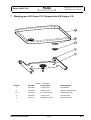
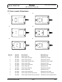
13. Power supply / Netzadapter
1
2
3
4
5
6
Key-No.
Part-No.
Description
Bezeichnung
1
350-8351
Power supply CH
Netzstecker CH
1
320-8024
Power supply CH IP65
Netzstecker CH IP65
2
350-8352
Power supply Schuko
Netzstecker Schuko
2
320-8025
Power supply Schuko IP65
Netzstecker Schuko IP65
3
350-8353
Power supply USA
Netzstecker USA
3
320-8026
Power supply USA IP65
Netzstecker USA IP65
4
350-8354
Power supply UK
Netzstecker UK
4
320-8027
Power supply UK IP65
Netzstecker UK IP65
5
350-8355
Power supply AUS
Netzstecker AUS
5
320-8028
Power supply AUS IP65
Netzstecker AUS IP65
6
350-8356
Power supply Schuko with ground
Netzstecker Schuko geerdet
6
320-8029
Power supply Schuko with ground IP65
Netzstecker Schuko geerdet IP65
Precisa Gravimetrics AG
Index -
A31
Section B: Electronics / Kapitel B:
Elektronik
Series 360 EP / ES
Section B: Electronics /
Kapitel B: Elektronik
Precisa Gravimetrics AG
Index -
B1
Main board / Hauptprint 360-7200-020
Series 360 EP / ES
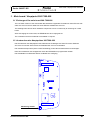
1. Main board / Hauptprint 360-7200-020
1.1 Exchange of the main board 360-7200-020
The new basic version of the main board 360-7200-020 is applicable for balances series EP with software A0x-xxxx-xxx and for balances series ES with software B0x-xxxx-xxx.
The drawing below shows which hardware component is to be converted by an exchange of a main
board.
After exchanging the main board, the EEPROM has to be reprogramed.
The schematics and bill of material are available on request.
1.2 Austauschen des Hauptprintes 360-7200-020
Die Grundversion des Hauptprintes 360-7266-020 ist für Waagen der Serie EP mit der Software
A0x-xxxx-xxx und der Serie ES mit der Software B0x-xxxx-xxx verwendbar.
Die markierte Komponente (siehe untere Darstellung) ist auf das Austauschboard zu übertragen.
Nach dem Austausch des Hauptprintes muss das EEPROM neu programmiert werden.
Die Schaltbilder und Stückliste stehen bei Bedarf zur Verfügung.
Measuring resistor
Messwiderstand
Precisa Gravimetrics AG
Index -
B2
Connector board / Steckerprint
360-7201-010
Series 360 EP / ES
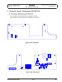
2. Connector board / Steckerprint 360-7201-010
2.1 Assembly / Bestückung 360-7201-010
The schematics and bill of material are available on request.
Die Schaltbilder und Stückliste stehen bei Bedarf zur Verfügung.
Upper side / Oberseite
Lower side / Unterseite
Precisa Gravimetrics AG
Index -
B3
Section C: Service
Series 360 EP / ES
Section C: Service
Precisa Gravimetrics AG
Index -
C1
Service tools and equipment
Series 360 EP / ES
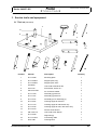
1. Service tools and equipment
1.1 Tool set (350-8537)
1
2
5
4
3
6
7
8
17
9
10
Position
11
14
12
13
16
15
Part-No.
Description
1
W 41-1688
Mounting plate
1
2
W 41-1688-5
Support post, long
2
3
W 41-1688-6
Support post, short
2
4
350-6203
Line-head screwdriver M4
1
5
240-7124
Screwdriver, small, no.1
1
6
PW 29-43-300
Pin for flexure holder
2
7
W 41-1700
Assembly jig with slot
1
8
W 41-1701
Assembly jig with hole
1
9
W 41-1677
Assembly pin for assembly jig
4
10
W 41-1691
Centring spigot for flexures
2
11
W 41-1774
Centring spigot for 360 series only
1
12
W 41-1675
Centring spigot for 320, 330 series only
1
13
W 41-1674
Flexure sheet anchor
1
14
PN 1100-172
Line-head screw M4x12
2
15
W 41-1699
Alignment jig
1
16
W 41-1578-8
Connecting cable
1
17
W41-1681
Centring bush
1
Precisa Gravimetrics AG
Index -
Quantity
C2
Service tools and equipment
Series 360 EP / ES
1.2 Equipment
1.2.1 Implements
• Soldering iron
• Tweezers
• Lens
• Voltmeter
1.2.2 Standard tools
• Allen key size 2,5
•
• Box spanner size 4, 5.5 and 7
• Flat-bladed screwdriver size 1, 2 and 4
• Phillips screwdriver size 2
Precisa Gravimetrics AG
Index -
C3
Opening up a balance
Series 360 EP / ES
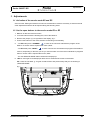
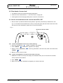
2. Opening up a balance
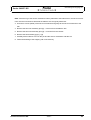
2.1 General procedure for opening up a Series 360 series balance
1. Disconnect the balance from the mains (Pull out mains plug)
2. Remove windshield, protective rings, weighing pan, pan holder
3. - Unscrew 2 cylindrical screws on the top of balance
- Unscrew 4 cylindrical screws on top if model is „A“ analytical or „SM“
- Unscrew 2 cylindrical screws on housing bottom if balanceI model is „A“ analytical or „SM“ sermi
micro.
4. Slightly raise the top of balance be carefull because key pad ribbon cable is connected to MPCB.
Disconnect ribbon cable from MPCB plug. Remove now fully housing‘s top.
Power cable pass for electric windshield
2 x Cylindrical screws
4 x Cylindrical screws
(„A“, „SM“ only)
2 x Cylindrical screws („A“, „SM“ only)
Precisa Gravimetrics AG
Index -
C4
Introduction / Preparation of the tools
Series 360 EP / ES
3. Introduction / Preparation of the tools
3.1 Introduction
In the event of a broken flexure, it is recommended that all are replaced.
NB: See page -----, repair set and page flexure sheet
The following assembly instructions provide information on how the flexures can be replaced most efficiently. It is important to employ a structured procedure for dismantling since it is essential to replace
the same parts (particularly screws) in the same place when re-assembling.
The various items of the assembly instructions mean:
(26/B3): component items -> 26 key no. to identify the component, B3 page of service manual
[5]: tooling items see “Service tools and equipment” on page C2
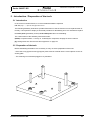
3.2 Preparation of the tools
Before dismantling the balance it is necessary to carry out some preparation of the tools.
- Place the 2 long [2] and 2 short [3] support posts must be screwed into the correct places on the assembly plate
- The soldering iron should be plugged in or preheated
Precisa Gravimetrics AG
Index -
C5
Dismantling the weighing cell
Series 360 EP / ES
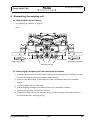
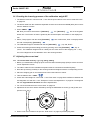
4. Dismantling the weighing cell
4.1 Removing the top of balance
• see “Opening up a balance” on page C4
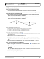
Fig. 1
Jig assembled
Jig assembled
Assembly jig right [8]
Assembly jig left [7]
Assembly pins [9]
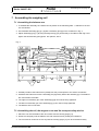
4.2 Removing the weighing cell from the bottom of balance
1. Loosen the the three screw nuts from balance bottom with box spanner size 7 to lift allow you then
to remove the weighing cell from the balance bottom housing
2. Loosen the two allen screws, on both side of the mass counterholder and remove calibration
weights
3. Loosen the display unit out of the clamp
4. Hold the weighing cell only on the chassis and lift it out of the bottom of balance
5. Placed on the assembly plate for easier handling
6. To protect the weigh cell, the two assembly jigs [7] + [8] are introduced in accordance with Fig. 1
and secured with the 4 assembly pins [9]
Precisa Gravimetrics AG
Index -
C6
Dismantling the weighing cell
Series 360 EP / ES
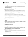
4.3 Removing the flexure-strap
1. Loosen the two screws (34/A8), remove flexure-strap (5/A8) incl. bases (10/A8) and spring washers
(11/A8) ( with the groups A only base (11/A8) mounted ) → Do not separate screw components,
assemble in same relationship
2. Screw the anchor [12] on tightly with 2 screws [13] in place of the flexure-strap
4.4 Removing the two flexure holders
1. Using the two pins for flexure holder [6] secure the upper flexure holder (4/A8) into the chassis
2. Unscrew the 4 screws (32/A8) of the upper flexure holder and remove together with the 4 spring
washers or the 4 bases (11/A8) → 2 on the chassis, 2 on the support piece
3. Remove the two pins with the upper flexure holder incl. 4 spring washers and the flexure sheets,
then take out the pins from the flexure holder
4. Secure the lower flexure holder into the chassis with the two pins for flexure holder [6]
5. Unscrew 4 screws (32/A8) from the lower flexure holder and remove together with the 4 spring washers or the 4 bases (11/A8) → 2 on the chassis, 2 on the support piece
6. Take out both pins with the lower flexure holder and remove the lower flexure holder together with
the 4 spring washers and the flexure sheets
4.5 Removing the coil
1. Carefully unsolder 2 connecting wires (3/A8) from the Sensor mechanism (17/A20) using the
tweezers
2. Unscrew 3 screws (31/A8) from the magnet cover (9/A8), remove the cover together with transport
safety device (6/A8) and spring washer (37/A8)
3. Unscrew 2 brass screws (27/A8) from the coil on the balance arm (20/A8) using a No.2 screwdriver,
remove the coil together with the washer
4. Carefully take out the coil from the pot
4.6 Removing the support piece
1. Unscrew 3 screws (36/A8) on the inner cone (17/A8) and remove inner cone
2. Unscrew upper screw (balance arm side) of the flexure sheet anchor [12] and pull off the support
piece together with the flexure sheet anchor over the assembly pins [9]
4.7 Removing the balance arm
1. Unscrew brass screw (26/A8) from the stopper (2/A8), turn the stopper inwards ca. 90° and gently
re-tighten the brass screw
2. Unscrew the 4 screws (33/A8) from the flexure sheets (7/A8) and remove both flexure sheets together with the bases (10/A8) and spring washers (11/A8) ( with the groups A only base (11/A8) mounted )
Precisa Gravimetrics AG
Index -
C7
Dismantling the weighing cell
Series 360 EP / ES
Note: Since the lug of the sensor mechanism is firmly attached to the balance arm, the sensor mechanism must be unscrewed to dismantle the balance arm and gently tilted back:
3. Unscrew 3 screws (30/A8) of the sensor mechanism and gently tilt the sensor mechanism to the
rear
4. Remove the two inner assembly pins [9] → unscrew from the balance arm
5. Remove the two outer assembly pins [9] → unscrew from the chassis
6. Remove the two assembly jigs [7] + [8]
7. Carefully tilt the balance arm over the pot and the sensor mechanism and take out
8. Further dismantling of the weighing cell is unnecessary
Precisa Gravimetrics AG
Index -
C8
Installing the new „H-flexure sheets“
Series 360 EP / ES
5. Installing the new „H-flexure sheets“
5.1 Removing the old „H-flexure sheets“
• Take out all screws from the flexure holder and remove the old „H-flexure sheets“ together with spring
washers
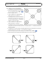
5.2 Installing the new „H-flexure sheets“
1. Place a flexure holder on the assembly plate [1] as in Fig.2
2. Select 4 new „H-flexure sheets“ (8/A8) → Place the new „H-flexure sheets“ carefully on the assembly plate [1] as in Fig. 2 → the slot of the sheet is always on the flexure holder
3. Place 4 spring washers (11/A8) on the „H-flexure sheets“ and screw these tightly to the flexure holder with 4 screws (29/A8)
4. Take the complete flexure holder carefully off the assembly plate → Do not touch the „H-flexure
sheets“! Prepare the second flexure holder in the same way
Fig. 2
Mark upside-down!
Precisa Gravimetrics AG
Index -
C9
Cleaning
Series 360 EP / ES
6. Cleaning
6.1 Cleaning the pot
1. Cut strips of a double-sided adhesive tape (ca. 2x2 cm)
2. Wind the adhesive tape around one end of a toothpick
3. Introduce the toothpick, adhesive tape first, vertically into the annular gap
4. With circular movements move it repeatedly around the magnet. In this way any dirt particles stick to
the adhesive tape
5. If necessary, repeat the procedure with a freshly prepared toothpick until the annular gap is free
from impurities
6. Wipe over the top of the pot magnet with a piece of adhesive tape
6.2 Cleaning the coil
1. Using a lint-free cloth, remove any contamination from the coil
2. Do not clean the coil with adhesive tape; risk of injury
6.3 Final check of cleaning
• Visually inspect the annular gap and the coil for any contamination and clean if necessary
Precisa Gravimetrics AG
Index -
C10
Assembling the weighing cell
Series 360 EP / ES
7. Assembling the weighing cell
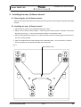
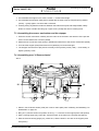
7.1 Assembling the balance arm
1. To facilitate the assembly, the chassis can be placed on the assembly plate → Attention to the sensor mechanism!
2. Pre-assemble assembly jigs [7] + [8] with 2 assembly pins [9] on the chassis as in Fig. 3
3. Adjust assembly jigs [7] + [8] using the alignment jig [14] horizontally in accordance with Fig.3 and
tighten the two assembly pins [9] with box spanner, size 4
Fig. 3
14
7
9
9
8
4. Carefully introduce the balance arm (20/A8) over the pot and past it to the sensor mechanism
5. Assemble the balance arm with 2 assembly pins [9] loosely behind the assembly jigs. The balance
arm must remain moveable
6. The right inner assembly pin of the assembly jig [8] can now be firmly tightened
7. The left inner assembly pin of the assembly jig [7] can now be firmly tightened
8. The balance arm is now fixed
7.2 Assembling the coil, the magnet cover and the transport safety device
1. Place the coil onto the balance arm and centre with the centring spigot [11]
2. Screw the coil tightly onto the balance arm with 2 brass screws (27/A8) and 2 washers
3. The coil must be centred in such a way that the centring spigot [11] can be removed smoothly
Precisa Gravimetrics AG
Index -
C11
Assembling the weighing cell
Series 360 EP / ES
4. Pre-assemble the magnet cover with 2 screws → screws left and right
5. Pre-assemble the transport safety device (6/A8) with the third screw (31/A8) and spring washer
(37/A8) → gently tighten, use line-haed screwdriver
6. Centring bush [16] shall be introduced between the balance arm-pilot and transportation safety
dewice to assure constant annular grap. Tigten screw (31/A8) and remove centring bush.
7.3 Assembling the sensor mechanism and the stopper
1. Press the sensor mechanism carefully into the cutout in the chassis in the direction of the pot and
secure to the chassis with 3 screws (30/A8)
2. Solder the two connection wires (3/A8) in parallel and strain-free to the sensor mechanism (24/A8)
3. Turn back the stopper (2/A8) with brass screw (26/A8) by 90° and screw tight
4. The stopper must be free of play and lie centrally in the symmetry screw (1/A8) → if necessary, readjust symmetry screw
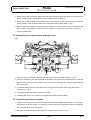
7.4 Assembling new “V-flexure sheets“
Abb. 4
10
10
1. Select 2 new V-flexure sheets (7/A8) see “How to order spare parts / Anleitung zur Bestellung von
Ersatzteilen” on page A2
2. Bring one „V-flexure sheet“ into position as in Fig. 4 → slots are on the support piece side (below)
3. With a centring spigot [10], centre the „V-flexure sheet“ in the hole on the chassis side (above)
4. With the second centring spigot [10], centre the „V-flexure sheet“ in the slot on the support piece
side (below)
Precisa Gravimetrics AG
Index -
C12
Assembling the weighing cell
Series 360 EP / ES
5. With the line-head screwdriver tighten the first (upper) centring spigot and then remove the second
(lower) centring spigot, without touching the „V-flexure sheet“ in doing so
6. Fasten the „V-flexure sheet“ on the balance arm side with base (10/A8), spring washer (11/A8) and
screw (33/A8), or with groups A with base (11/A8) and screws (33/A8) fixate → Fig. 4
7. Remove the second (upper) centring spigot and fasten the „V-flexure sheet“ on the chassis side with
base (10/A8), spring washer (11/A8) and screw (33/A8), or with groups A with base (11/A8) and
screws (33/A8) fixate
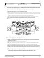
7.5 Assembling the support piece and inner cone
Fig.5
12
9
13
9
1. Introduce the pre-assemble support piece over the two inner assembly posts [9] → Fig. 5
2. It must be possible to push the support piece smoothly over the two inner assembly pins. In case the
support piece can not pushed smooth-running over the two assembly pins, unscrew pin [9] and tighten it again after.
3. Locate the support piece and the balance arm using the flexure sprap anchor [12] and the two
screws [13] → Fig. 5
4. The support piece and balance arm are now fixed.
5. Assemble the inner cone (17/A8) to the support piece with 3 screws (36/A8)
7.6 Assembling the flexure holders
1. Introduce the two pins for flexure holder [6] in the first pre-assembled flexure holder (→ see “Installing the new „H-flexure sheets“” on page C9) in such a way that the shoulder of the pins is opposite
the screw heads on the flexure holder
2. Bring the two pins with the flexure holder into position in the chassis → Fig. 5
Precisa Gravimetrics AG
Index -
C13
Assembling the weighing cell
Series 360 EP / ES
3. Lower the flexure holder carefully over the two pins on the chassis, until the flexure sheets just touches the chassis and the support piece
4. Secure the flexure holder with 4 screws (32/A8) uand 4 spring washers (11/A8)
5. Push through the two pins up to the installed flexure holder
6. On the opposite side introduce the second pre-assembled flexure holder (→ see “Installing the new
„H-flexure sheets“” on page C9) with the screw heads inwards over the two pins and lower onto the
chassis, until the flexure sheets just touches the chassis and the support piece
7. Secure the flexure holder with 4 screws (32/A8) and 4 spring washers or the 4 bases (11/A8)
8. The two pins must be capable of being withdrawn smoothly from the flexure holder
Fig. 6
6
6
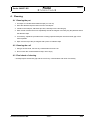
7.7 Assembling the new „flexure-strap“
1. Select a new „flexure-strap“ (5/A8) see “How to order spare parts / Anleitung zur Bestellung von
Ersatzteilen” on page A2
2. Unscrew 2 screws [13] on the anchor [12] and remove it
3. Bring the „flexure-strap“ into position as shown in Fig.7 → the slot is on the support piece side
4. Using a centring spigot [10], centre the „flexure-strap“ in the hole on the balance arm side
5. With the second centring spigot [10] centre the „flexure-strap“ in the slot on the support piece side
6. Tighten the first (upper) centring spigot and then carefully remove the second (lower) centring spigot, without touching the „flexure-strap“ in doing so
7. Fasten the „flexure-strap“ on the support piece side with base (10/A8), spring washer (11/A8) and
screw (34/A8), or with groups A with base (11/A8) and screws (33/A8) fixate → Fig. 7
Precisa Gravimetrics AG
Index -
C14
Assembling the weighing cell
Series 360 EP / ES
8. Remove the second (upper) centring spigot and fasten the „flexure-strap“ on the balance arm side
with base (10/A8), spring washer (11/A8) and screw (34/A8), or with groups A with base (11/A8) and
screws (34/A8) fixate
Fig. 7
7.8 Dismantling the assembly jigs
1. Unscrew and remove the two inner assembly pins [9] on the support piece
2. Unscrew and remove the two outer assembly pins [9] on the suport piece
3. Take out the two assembly jigs [7] + [8] from the side
4. If the two assembly pins [6] on the flexure holder (4/A8) are still assembled, remove them carefully
7.9 Installing the weighing cell in the bottom of balance
1. Carry out a further movement check on the balance arm → the balance arm must not touch the
transport safety device (6/A8). Visual check with the lens
2. Place the weighing cell carefully in the bottom of balance → hold the weighing cell only to the chassis
3. Tilt the bottom of balance to the side and screw the weighing cell securely from below with 3 nuts
4. Carefully connect the sensor mechanism (24/A8) plug to the main board (8/A4)
5. The balance is now ready for the adjustments on the following pages
6. Insert the calibration weights and mount the counterholder with two allen screws per side, using box
spanner, size 2.5
Precisa Gravimetrics AG
Index -
C15
Section D: Adjustments
Series 360 EP / ES
Section D: Adjustments
Precisa Gravimetrics AG
Index -
D1
Adjustments
Series 360 EP / ES
1. Adjustments
1.1 Activation of the service mode ES and EP
Good to know: Setting the balance into service & maintanance mode is necessary to achieve several
other adjustements which will be required along the following items.
1.2 Set the open balance to the service mode ES or EP
1. Balance is disocnnected from mains.
2. Level the balance with the levelling feet, rear of the balance.
3. Remove the jumper (J1) on right side of the display, fig. 1.
4. Connect the balance to the mains, balance is switching on automaticly.
5. - On ES model press «CHANGE»
to enter in the service & maintenance program of the
balance. If access code is required then enter „5236“
- On EP model press «MENU»
to enter in the service & maintenance program of the balance.
Later on, depending on the item you are you need to select one of the three maintenance programs
listed. If access code is required then enter „5236“
- You see SERVICE MODE status confirmed on display top.
6. NB: Do not forget to reinstall jumper after service & maintenance work is terminated.
NB II: Also the unit letter „g“ for gram remains frozen and proves easily that you are working in
„SERVICE MODE“.
fig. 1
J1
S3
D1
Precisa Gravimetrics AG
Index -
D2
Adjustments
Series 360 EP / ES
1.3 Adjusting of the symmetry ES and EP
1. Connect the connecting cable [16/C2] from tool set see “Tool set (350-8537)” on page C2 to plug S3
on the MPCB (see fig. 1).
NB: For better access disconnect display board from holder, one side only, opposite side will releasing easily.
2. Connect the voltmeter, set it to „DC“ measurement, to the connecting cable [16/C2].
3. The voltmeter must show approximately the same voltage in both end positions. Lifted up and pressed down position of the balance arm. Same voltage, meant is closed figure like (fictitious value) ~+
2,43 and ~-2,35 (one positive, one negative).
4. If the difference is too great, the extremity position of the balance arm needs to be adjusted with the
symmetry screw [1/A8].
5. Once adjusted detach connecting cable and voltmeter from the balance.
1.4 Checking the pre-load ES and EP
1. The pre-load error ERROR 60 (below minimal converter range) must not appear when the service
weighing pan is in position without load.
2. The pre-load error ERROR 61 (above maximal converter range) must not appear when the service
weighing pan is in position with full load.
3. If an ERROR is displayed:
- the symmetry must be re-adjusted
- and the transport safety device adjusted and checked if friction is caused
- general check of the complete weighing cell.
1.5 Checking the lowering process of the calibration weight ES
1. The balance must be in service mode → see “Set the open balance to the service mode ES or EP”
on page D2.
2. The ribbon cable from the membrane keyboard must be connected to the MPCB (8/A4) and connect
the balance then to mains.
3. Press and hold down «CHANGE»
until „TESTPROG 1“ appears on Info-Display, release then
the key.
4. The calibration weight is actuated with the two {SOFTKEY}
actuation by the {SOFTKEY}
„AUF“ (UP) and „AB“ (DOWN),
below the corresponding description.
5. Check the lowering and ascending process by pressing one of the {SOFTKEY}
. The calibra-
tion weight must run cleanly into the outer carrier of the weighing cell → carry out a full re-alignment
of the calibration unit in the housing‘s bottom.
Precisa Gravimetrics AG
Index -
D3
Adjustments
Series 360 EP / ES
1.6 Checking the lowering process of the calibration weight EP
1. The balance must be in service mode → see “Set the open balance to the service mode ES or EP”
on page D2.
2. The ribbon cable from the membrane keyboard must be connected to the MPCB (8/A4) and connect
then the balance to mains.
3. Press «MENU»
NB: Now you need to work with the {SOFTKEY}
, the {SOFTKEY}
are on the keypad‘s
bottom line. The function of them is guided by the short description information on the display bottom.
4. Select „Test program“ with the arrow {SOFTKEY}
line with corresponding {SOFTKEY}
then confirm with „enter“ on display bottom
.
.
5. The calibration weight is actuated with the two {SOFTKEY}
„Up“ and „Down“.
6. Check the lowering and ascending process by pressing one of the {SOFTKEY}
„Up“ or
„Down“. The calibration weight must run cleanly into the outer carrier of the weighing cell → carry
out a full re-alignment of the calibration unit in the housing‘s bottom.
1.7 Adjusting the corner load
1.7.1 For models with accuracy 1 g, 0,1 g, 0,01 g, 0,001 g
1. Before you reassamble housing top push out from inside both blind plugs (9/A6) to assure access to
corner adjustment screws.
2. The ribbon cable from the membrane keyboard must be connected to the MPCB (8/A4)
3. Draw the top-housing carefully on the housing‘s bottom and tighten with the corresponding screws.
4. Place the weighing pan on the balance and connect the balance to mains.
5. Tare the balance with «TARE»
6. Check with a test weight for corner load → see “Final check” on page H9 the difference between the
two diagonals A-C and B-D → see “Example of corner load adjustment:” on page D5. The diagonal
with the larger absolute deviation should be adjusted first.
7. For corner load tolerances see “Final check” on page H9
8. Adjustment of the corner load is effected by turning the differential set screw (1) and (2) with „box
spanner“ tool, size 7.
2
1
9. When corner are in tolerance as per see “Final check” on page H9 put blind plug back.
Precisa Gravimetrics AG
Index -
D4
Adjustments
Series 360 EP / ES
1.7.2 Example of corner load adjustment:
1. The diagonal A-C has the larger difference.
2. Place a test weight at point C of the weighing
pan. Tare the balance using «TARE»
3. Move the weight to point A.
4. There is a difference of 12 digits between
points A and C (A=12, C=Tare=0).
5. The displayed value for point A is reduced by
turning the corner load screw 1 above point A
in an anti-clockwise direction → the difference
between A-C becomes smaller.
6. There is a difference of 7 digits between
points B and D (B=-7, D=Tare=0).
7. The displayed value for point B is reduced by
turning the corner load screw 2 above point B in a clockwise direction → the difference between BD becomes smaller.
8. The diagonals A-C and B-D should be repeatedly adjusted until the two diagonals have reached the
permitted tolerances for corner load → see “Final check” on page H9.
9. Place a test weight on point Z of the weighing pan, tare balance using «TARE»
.
10.Check the points A-B-C-D against the permitted tolerances and correct if necessary.
T
T
2
1
2
+
-
T
T
1
-
+
Precisa Gravimetrics AG
Index -
D5
Adjustments
Series 360 EP / ES
1.8 Final check of corner load
1. The balance must have reached operating temperature.
2. Check the corner load tolerance → see “Final check” on page H9.
3. Insert again the two blind plugs (9/A6) when corners are in tolerance.
1.9 Set the closed balance to the service mode ES or EP
1. Service switch is positioned below housing bottom, right side, protected by a slotted screw, see
fig. 2. To acceed unscrew slotted screw, see fig. 2 and press gently with the small screw driver from
the tool set or with a bended up „paper clip“ on the service switch.
Fig. 2
Access to service switch
1.9.1 Set the closed balance into service mode, ES only
1. Push the CHANGE-key
2. Press «ENTER»
0/T
„CODE 0“ appears in the display.
„CODE 0000“ appears in the display.
3. With the „arrow- {SOFTKEY}
«ENTER»
on the key pad bottom, insert the code „5236“ and confirm with
0/T
4. Balance is now in service mode.
1.9.2 Set the closed balance into the service mode, EP only
1. SERVICE is written on the top of the disply as confirmation that you are in the service & maintenance program of the balance.
2. Push «MENU»
.
3. Select one of the three maintenance programs you need to work with.
Precisa Gravimetrics AG
Index -
D6
Adjustments
Series 360 EP / ES
1.10 Linearisation of the balance
1. The balance must have reached operating temperature and be in service mode → see “Set the closed balance to the service mode ES or EP” on page D6.
2. Have weights of 1/2 full load and full load ready → see “Final check” on page H9.
3. - For ES: Press and hold «CHANGE»
until "LINEARITY" appears on the info-display and then
release the key.
- For EP: Select service program linearisation with the arrows {SOFTKEY}
and confirm with
enter {SOFTKEY}
4. ES and EP show on display bottom, in correspondence with the key pad line the three linearisation
weights in „g“ which correspond, to the balance empty pan no load, to 1/2 weight capacity and to 1/
1 full balance capacity. A fictitious example: „0“,“300“ „600“ and the last key to confirm the established linearisation points, confirm with SET with the {SOFTKEY}
ES model. On EP with the {SOFTKEY}
below the SET writing, on
below the „ENTER“ writing on display bottom.
1.11 Adjustment of the internal calibration weight
1. The balance must have reached its operating temperature
2. Disconnect the balance from the power supply and reconnect, allow the balance to restart normally
3. Push the service switch
NOTE: The jumper J1 must be in place!
4. Have weight of 100g ready.
5. Press and hold down the T-key until "CALIBRATION" appears on the Info-Display, then release
6. The process of internal calibration weight adjustment will be initialised "INTERNAL CALIBRATION"
will appear on the Info-Display and the balance will show "INT"
7. "EXTERNAL CALIBRATION" will appear on the Info-Display and the balance will first show "0000"
8. If the balance displays, "100", it requires a weight of this value
9. Place a weight of 100g in the centre of the weighing pan, the balance will flash
10. If the balance again shows "0000", remove the weight from the weighing pan
11. The balance terminates the external calibration and "INTERNAL CALIBRATION" will again appear
on the Info-Display and the process will automatically terminate
12. The balance is switched off and on again and service mode is abandoned
1.12 Final check of the adjustment
1. The balance must have reached its operating temperature, for that assure that balance is connected
at least three hours to the mains.
2. Calibrate the balance by holding «TARE»
till „CALIBRATION“ appears → release the key.
3. Check the corner load → see “Adjusting the corner load” on page D4.
4. Check the linearity with half weight and full weight.
5. Carry out any S-corrections if necessary for evaluation see “S-correction of a balance” on page D8.
Precisa Gravimetrics AG
Index -
D7
Adjustments
Series 360 EP / ES
1.13 S-correction of a balance
1.13.1 General notes on S-correction
• The balance must have reached its operating temperature and must be in service mode.
• In every linearisation of a balance the correction factor is deleted and must, if necessary, be redefined.
1.13.2 Measuring the S-correction ES and EP
1. Place a weight of 1/4 full load in the centre of the weighing pan, note the difference between the
actual weight and the weight indicated by the balance.
2. Place a weight of 3/4 full load in the centre of the weighing pan, note the difference between the
actual weight and the weight indicated by the balance.
Sb
Sa
1.13.3 Calculating the correction factor
• For the correction factor the sign of the measured value must be reversed.
• for example: + 4 digits were measured →- 4 digits must be entered.
• for example: - 2 digits were measured →+ 2 digits must be entered.
1.13.4 Entry of the correction factor for ES model
1. Press and hold down the CHANGE-key
until "SCORRECTION" appears on the Info-Display,
then release the key.
2. By pressing the arrow left or right select section A or B
3. To change the section values press arrow keys "UP" or "DOWN" the values setted are safed as
soon you quit the correction menu with the „esc“ {SOFTKEY} you see the S-correction modification.
4. Submit the balance to a further final check → see “Final check of the adjustment” on page D7.
1.13.5 Entry of the correction factor for EP model
1. Select service program S-correction with the arrows {SOFTKEY}
and confirm with enter
{SOFTKEY}
2. On display bottom you find the denominated S-correction areas corresponding to the
{SOFTKEY}.
NB: On the display lower side on left corner over the „esc“ writing you can read the changing of Scorrection values you are implementing.
3. Confirm all changes with {SOFTKEY} „enter“
Precisa Gravimetrics AG
Index -
D8
Final check
Series 360 EP / ES
2. Final check
Balance
Weighing Readarange
ES as EP
Reprodu-
Linearity
Linearity
bility
cibility
Weight
Tolerance
Weight
Tolerance
(+/-)
(g)
(+/-)
(g)
(+/-)
0.03 mg
2 x 50
0.06 mg
50
0.1 mg
2 x 100
0.2 mg
0,06 mg
100
0.5 mg
(g )
Corner load Corner load
125 SM
125
0.01 mg
225 SM-DR
225
0.01 mg / 0.01 mg / 0.1
0.1 mg
mg
120A
120
0.1 mg
0.1 mg
2 x 100
0.2 mg
50
0.2 mg
220A
220
0.1 mg
0.1 mg
2 x 100
0.2 mg
100
0.2 mg
320A
320
0.1 mg
0.15 mg
1x 50
1x 100
1x 200
0.2 mg
100
0.2 mg
420A
420
0.1 mg
0.15
2x 200
0.4 mg
100
0.2 mg
520A
520
0.1 mg
0.15
1x 50
1x 100
2x 200
0.4 mg
200
0.2 mg
120 - 420
0.1 - 0.01
0.15 / 1mg
2x 200
0.3 / 1 mg
100
0.2 mg
320M
320
1 mg
1 mg
2 x 150
1.5 mg
100
2 mg
620M
620
1 mg
1 mg
2 x 300
1.5 mg
200
2 mg
920M
920
1 mg
1 mg
1x 50
1x 400
1x 500
1.5 mg
200
2 mg
1220M
1220
1 mg
1 mg
2x 100
1x 1000
2 mg
400
2 mg
2220M
2220
1 mg
1 mg
2x 100
2x 1000
2 mg
500
2 mg
620M-FR
120 - 620
1 / 10 mg
1 / 10 mg
2x 300
1.5 mg
200
2 mg
1220M-FR
240 - 1220 1 / 10 mg
1 / 10 mg
2x100
2x 1000
1.5 / 10 mg
400
2 mg
420A-FR
1200C
1200
10 mg
10 mg
2 x 600
10 mg
400
20 mg
2200C
2200
10 mg
10 mg
2 x 100
2x 1000
15 mg
1000
20 mg
4200C
4200 g
10 mg
10 mg
2 x 100
2x 2000
15 mg
2000
20 mg
6200C
6200 g
10 mg
10 mg
2 x 3000
15 mg
2000
20 mg
6200C-FR
6200
2200
0.1
0.01
0.1
0.01g
2 x 3000
0.1 g
0.015 g
2000
30 mg
8200C-FR
8200
3200
0.1
0.01
0.1
0.01
2 x 100
2x 4000
0.1 g
0.015 g
4000
30 mg
6200 D
6200 g
0.1 g
0.1 g
2 x 3000
0.1 g
2000
0.2 g
8200D
8200 g
0.1 g
0.1 g
2 x 4000
0.15 g
3000
0.2 g
12200D
12200 g
0.1 g
0.1 g
2x 100
2x 6000
0.15 g
4000
1g
12200G
12200 g
1g
0.5 g
2x 100
2x 6000
0.15 g
4000
1g
Precisa Gravimetrics AG
Index -
D9
Error messages
Series 360 EP /ES
3. Error messages
3.1 Operating error
(Error disappears with correct use or application)
ERROR-No.
ERROR responsibility
ERROR repair
ERROR 1
invalid program
load right program
ERROR 2
value out of range density-program
use right weight
ERROR 3
weight too small
use higher weight
ERROR 4
wrong anti-theft-code
use right code
ERROR 5
wrong anti-theft-code
use right code
ERROR 8
zero point outside range
call service
ERROR 9 / 0
calibration factor bad
repeat calibration
ERROR 9 / 1
zero point difference too high
repeat calibration
ERROR 9 / 2
difference of internal weight too high
repeat calibration
ERROR 9 / 3
calibration factor bad
repeat calibration
ERROR 9 / 4
wait
ERROR 15 / 1
Supply to low
use right power supply
ERROR 15 / 2
Supply to high
use right power supply
ERROR 29
no Delta-temperature-compensation-referenc
repeat calibration
ERROR 30
no internal reference weight
acknowledge with TARE-key
ERROR 31
no external reference weight
acknowledge with TARE-key
ERROR 41
name already used
use an other name
ERROR 42
name invalid
use an other name
ERROR 47
too many values
use fewer values
ERROR 48
different first unit from input
use the original unit
ERROR 49
too few values
use more values
ERROR 53
values out of range +/- 50%
use appropriate weight
ERROR 60
fallen below minimum transformer area
call service
ERROR 61
maximum transformer area exceeded
call service
ERROR 80
too few values
add sample
ERROR 81
too many sample
cance sample
ERROR 90
no disc free
cancel disc
ERROR 91
no disc saved
add disc
ERROR 92
no sample
add sample
3.2 Fatal error
(Balance stays still, error repair in service mode)
ERROR-No.
ERROR responsibility
ERROR repair
ERROR 10
no linearisation values
repeat linearisation
ERROR 11
no calibration factor
repeat calibration
ERROR 12
keine SCS Einschalt-Drift Werte
call service
ERROR 21
no SCS temperature compensation values
call service
ERROR 22
no temperature compensation values
call service
ERROR 23
no SCS temperatur no-linearity compensation values
call service
Precisa Gravimetrics AG
Index -
D10
Error messages
Series 360 EP /ES
3.3 Hardware error
(Balance stays still)
ERROR-No.
ERROR responsibility
ERROR repair
ERROR 14
wrong model code
call service
ERROR 16
internal RAM destroyed
replace CPU
ERROR 17
external RAM destroyed
replace RAM
ERROR 18 / 1
wrong program check sum
load right program, replace FLASH
ERROR 18 / 2
no approved program build in approved balance
load right program
ERROR 18 / 8
FLASH empty
load right program, replace FLASH
ERROR 18 / 9
wrong controller check sum
replace CPU
ERROR 19
wrong code figure
load right code figure
ERROR 20 / 1
temperature measurement Zelle defective
call service
ERROR 20 / 2
temperature measurement magnet defective
call service
ERROR 20 / 4
ADC-reference-sensor defective
call service
ERROR 28
no temperature values in °C
call service
Precisa Gravimetrics AG
Index -
D11
Discussion with the manufacturer
Series 360 EP / ES
4. Discussion with the manufacturer
In discussions with the manufacturer‘s works the following information should be provided:
• Balance type e.g. XR 405A
• Order number e.g. 320-9802-005 (Label on the underside of the balance)
• Sales number e.g. No. T20753 (Label on the underside of the balance)
• Series number e.g. 2602-16 (Label on the rear of the balance)
• Program number e.g. 00,00,A40 V00 (appears on the display when switching on the balance)
• As precise a description of the defect as possible
• Weighing results
• Preparation of the samples
PRECISA Gravimetrics AG
Moosmattstrasse 32
Po-Box 352
CH-8953 Dietikon
Tel. +41 44 744 28 28
Fax. +41 44 744 28 38
e-mail: [email protected]
Internet: http://www.precisa.com
Subject to technical modification
Precisa Gravimetrics AG
Index -
D12