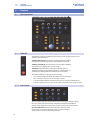
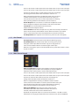
1
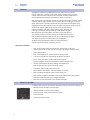
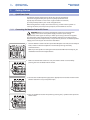
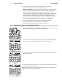
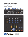
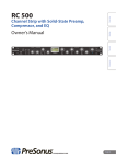
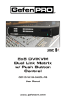
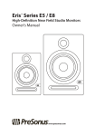
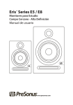
Monitor Station V2
Desktop Studio Control Center
Owner’s Manual
®
www.presonus.com
English
Table of Contents
3Hookup — 14
1Overview — 1
3.1
1.1
Introduction — 1
1.2
Features — 2
1.3
What’s in the Box — 2
2
Getting Started — 3
2.1
Quick Start Guide — 3
2.1.1
Connecting the
Monitor Station V2’s Power — 3
2.1.2
Connecting Devices to the
Monitor Station V2’s Inputs — 4
2.1.3
3.1.1Inputs — 14
Setting the Output Level of Your
Audio Sources — 5
2.1.5
Connecting Speakers to the
Monitor Station V2 — 6
2.1.6
Calibrating Your Speaker Levels — 7
2.1.7
3.1.2
Speaker Outputs — 14
3.1.3
Line Outputs — 15
3.1.4Power — 15
4Controls — 16
4.1
The Front Panel — 16
4.1.1Talkback — 16
Calibrating the
Monitor Station V2’s LED Meter — 5
2.1.4
The Back Panel — 14
4.1.2
Cue Control — 16
4.1.3
Aux Control — 17
4.1.4
Main Source Control — 17
4.1.5
Speaker Control — 18
4.1.6
Main Level Controls — 18
5Resources — 19
5.1
Audio Specifications — 19
Calibrate the Talkback Microphone — 10
5.2
Frequently Asked Questions — 21
2.1.8
Connect the Cue Outputs — 10
5.3
Troubleshooting — 21
2.1.9
Connect the Main Outputs — 11
5.4
PreSonus Limited Warranty — 22
2.2
Basic Hookup Diagram — 12
2.3
Advanced Modes — 13
2.3.1
Speaker Select Modes — 13
2.3.2
Main and Cue Source Modes — 13
2.3.3
Input LED Meter Modes — 13
2.3.4
Reset All Modes to the
Factory Default — 13
1Overview
1.1Introduction
Monitor Station V2
Owner’s Manual
1Overview
1.1
Introduction
Thank you for purchasing the Monitor Station V2. As with all PreSonus® products,
it’s built with high-grade components to ensure optimum performance that lasts
a lifetime. The Monitor Station V2 is based on the acclaimed Monitor Station,
with a new ergonomic design that makes it even easier to use. It also features
new input options for today’s engineers, producers, and artists. The result is the
perfect desktop monitoring and communications system for the modern studio.
Please contact us at 1-225-216-7887 with any questions or comments
you have about your Monitor Station V2. PreSonus Audio Electronics is
committed to constant product improvement, and we highly value your
suggestions. We believe the best way to achieve our goal of constant product
improvement is by listening to the real experts: our valued customers.
We recommend you read this manual to familiarize yourself with the
Monitor Station V2’s features, applications, and connection procedures
before trying to connect it to other equipment. This can prevent
problems that might otherwise occur during installation and setup.
We appreciate the support you have shown us through the purchase of this
product and are confident that you will enjoy your Monitor Station V2!
1
Monitor Station V2
Owner’s Manual
1Overview
1.2Features
1.2
Features
The Monitor Station V2 is outfitted with the key monitor-management
features needed in a modern studio. High-quality components ensure that
it doesn’t color the sound of your tracks and mixes. Its built-in Talkback mic
makes communicating with your performers simple and painless.
The stereo inputs in the Monitor Station V2 accommodate audio interfaces, mixing
consoles, outboard gear, phones, personal music players, CD players, and many
other audio sources. Up to four input sources can be monitored, together or by
toggling between input and Aux sources for quick comparisons or for reference.
Three stereo outputs allow you to connect three sets of powered
reference monitors and easily switch between them. Manage your
listening environment during recording and playback using the
Monitor Station V2’s master Mute, Dim, Mono, and Level controls.
The individual Source and Level controls for the Monitor Station V2’s
four amplified headphone outputs allow you to individually configure
and adjust what’s heard in each performer’s headphones.
All of this makes the Monitor Station V2 a powerful tool for
monitoring your recording and mixing sessions.
Summary of Features
•• Four stereo analog inputs: two stereo pairs of balanced ¼” TRS, one
unbalanced stereo 1/8” TRS, and one stereo pair of unbalanced RCA inputs
•• S/PDIF digital input
•• Main Source buttons for selecting and comparing inputs
•• Cue Source selectors for customizing headphone Cue mixes
•• Three stereo pairs of balanced ¼” TRS speaker outputs
•• Speaker output trims for fine calibration of speaker output levels
•• Speaker Select buttons for quick A/B’ing of selected input
sources between connected monitoring systems
•• Dim button with variable attenuation level
•• Mono button, Mute button, and Main Output Level knob
•• Built-in Talkback microphone with variable input gain
•• Four built-in headphone amplifiers with stereo, unbalanced ¼” TRS outputs
•• Individual Level knobs for each headphone output
•• Main/Cue Source selector for each headphone output
1.3
What’s in the Box
In addition to this manual, the Monitor Station V2 package contains the following:
•• Monitor Station V2 Studio Control Center
•• Monitor Station V2 external power supply
•• PreSonus Health Safety and Compliance Guide
•• PreSonus sticker
•• PreSonus product catalog
2
Monitor Station V2
Owner’s Manual
2
2.1
Getting Started
Quick Start Guide
2
Getting Started
2.1
Quick Start Guide
The Monitor Station V2 Quick Start Guide will help get your Monitor
Station V2 integrated with your system as quickly as possible. These
step-by-step instructions are based on a typical studio environment;
your setup will depend on your needs and applications.
Note: Throughout this chapter, we’ll refer to turning a knob all the way down as
“zeroing” the knob, since for practical purposes, the knob will be set to “0.”
2.1.1 Connecting the Monitor Station V2’s Power
WARNING: Before connecting the Monitor Station V2’s included power
supply, make sure that the power supply meets the input-voltage
requirements of the region or country in which you’re using it. PreSonus supports
only the power supply shipped with your Monitor Station V2. If the power supply
doesn’t meet your local requirements, or if you wish to purchase an additional power
supply, please contact your local dealer or distributor.
1. Zero the Monitor Station V2’s front-panel Main Output Level knob, the Cue Output
knob, and the individual headphone Level knobs by turning them fully
counterclockwise.
Note: If you have speakers or other gear connected to the Main L/R Line Outputs, you
should also zero their own output controls.
2. Make sure the Monitor Station V2’s rear-panel Power switch is turned off by
pressing the “0” at the bottom of the switch.
3. Connect the included power supply to the appropriate wall socket and then to the
Monitor Station V2’s rear-panel power input.
4. Turn on the Monitor Station V2’s power by pressing the “|” symbol at the top of the
Power switch.
3
2
2.1
Getting Started
Quick Start Guide
Monitor Station V2
Owner’s Manual
2.1.2 Connecting Devices to the Monitor Station V2’s Inputs
1. Zero the Monitor Station V2’s front-panel Main Output Level knob, the Cue Output
knob, and the individual headphone Level knobs by turning them fully
counterclockwise.
2. Connect your primary audio source (computer audio interface, mixer, or other
stereo source) to the balanced ¼” TRS ST1 L/R inputs on the back of your Monitor
Station V2.
3. If you have a secondary stereo audio source or cue audio source—such as other
interface outputs or the auxiliary outputs of your mixer—connect it to the
balanced ¼” TRS ST2 L/R inputs.
The Monitor Station V2 can accommodate a variety of analog
and digital input sources. Here’s how to attach them.
Phone, personal music player, or other device with 1/8” stereo output. Connect
the output to the rear-panel 1/8” Aux In jack using an unbalanced, stereo 1/8” cable.
(With a phone or personal music player, the headphone jack is its output.)
Analog audio device with RCA outputs. Connect the device’s outputs to the
Monitor Station V2’s rear-panel unbalanced RCA AUX L/R IN jacks.
4
2
2.1
Getting Started
Quick Start Guide
Monitor Station V2
Owner’s Manual
Digital audio device with S/PDIF output. Connect the source device’s S/PDIF
output to the Monitor Station V2’s rear-panel RCA (coaxial) S/PDIF input. The Monitor
Station V2 supports sample rates of 44.1, 48, 88.2, and 96 kHz.
Note: The RCA and 1/8 analog Aux In jacks are summed and can be used at the same time.
Control their volumes relative to each other using their individual output controls. Switch
between the analog Aux inputs and digital S/PDIF inputs as described in Section 4.1.3.
2.1.3 Calibrating the Monitor Station V2’s LED Meter
By default, the Monitor Station V2’s LED meters are calibrated so that the red 0 VU
LED illuminates when the selected source signals reach +10 dBu. This can be
changed so that 0 VU references +4, +10, or +18 dBu.
+4 dBu. 0 VU should reference +4 dBu if any of your monitoring devices
has a maximum input of +4 dBu or if none of your input devices has
a maximum (or nominal) output level greater than +4 dBu.
Press and hold the Cue Source ST1 button while
powering on your Monitor Station V2.
+10 dBu. 0 VU should reference +10 dBu if any of your monitoring
devices has a maximum input of +10 dBu or if none of your input devices
has a maximum (or nominal) output level greater than +10 dBu.
Press and hold the Cue Source ST2 button while
powering on your Monitor Station V2.
+18 dBu. 0 VU should reference +18 dBu if any of your monitoring
devices has a maximum input of +18 dBu or if none of your input devices
has a maximum (or nominal) output level greater than +18 dBu.
Press and hold the Cue Source Aux button while
powering on your Monitor Station V2.
2.1.4 Setting the Output Level of Your Audio Sources
Your audio sources sound their best through the Monitor
Station V2 when their outputs are set correctly.
To optimally set the output level of an audio source, the source should
be able to produce a 1 kHz sine-wave test tone, either by playing one
back or by generating it from an internal oscillator. You can find and
download free test tone audio files from the internet if necessary.
When using a test tone, make sure there’s no processing—EQ, compression, reverb,
and so on—in your test tone’s audio path so the tone is as clean as possible.
1. Zero the Monitor Station V2’s front-panel Main Output Level knob, the Cue Output
knob, and the individual headphone Level knobs by turning them fully
counterclockwise.
2. Turn down the outputs of the primary audio source
connected to ST1 to their lowest setting.
3. From your primary audio source, play your 1 kHz sine-wave tone at a level of 0 dB.
4. On the Monitor Station V2, press the ST1 Main Source button
so that it lights to select the primary audio source; make sure
that no other Main Source buttons are turned on.
5
2
2.1
Monitor Station V2
Owner’s Manual
Getting Started
Quick Start Guide
5. Turn up the output level control of your primary audio source until
the Monitor Station V2’s LED meter’s red 0 VU LED lights.
Reality vs. Unity Gain: The master output fader or knob on many audio devices
has a Unity Gain marking that shows the position at which the output’s level
isn’t being raised or lowered and is therefore at its optimal position. This is
usually marked as a “0” setting. If you find that the output setting of your audio
source needs to be way above or below its Unity Gain marking in order to light
the Monitor Station V2’s 0 VU LED, you may need to recalibrate the Monitor
Station V2’s LED meter to better accommodate the device. Adjust the meter’s
range as described in Section 2.1.3, then repeat steps 2-5 in this section.
6. For the audio sources connected to the ST2 and Aux Inputs, repeat
steps 2-5, selecting the appropriate source in step 4. (Ideally,
these devices also need to be able to produce a test tone.)
2.1.5 Connecting Speakers to the Monitor Station V2
1. Zero the Monitor Station V2’s front-panel Main Output Level knob and rear-panel
Speaker A Out trim by turning them fully counterclockwise.
2. Connect your primary monitoring system (such as a pair of powered nearfield
reference monitors) to the Monitor Station V2’s A L/R Speaker outputs.
3. If you have a second set of monitors, connect them to the Monitor Station V2’s B
L/R Speaker outputs.
4. If you have a third pair of monitors or a subwoofer, connect them to the Monitor
Station V2’s C L/R Speaker outputs.
Note: If using a subwoofer, make sure the Monitor Station V2 is set to Combo mode or
Toggle A/B mode, as described in Section 2.3.1.
6
2
2.1
Getting Started
Quick Start Guide
Monitor Station V2
Owner’s Manual
2.1.6 Calibrating Your Speaker Levels
Speaker calibration sets the output level of your speakers so that
a specific level shown on the Monitor Station V2’s meter equals a
specific acoustic level in your studio as measured in dB SPL. The
meter level most typically used for calibration is 0 VU.
Calibrating your speakers provides a few important benefits. First, calibration
establishes a comfortable maximum level for your studio environment.
A healthy monitoring level for a small control-room environment would
be 78 dB. For a large environment, 85 dB makes more sense. You can
estimate the best listening level for room sizes in-between.
Calibration also ensures that your left and right speakers are precisely balanced
with each other. This enhances stereo imaging and, more critically, allows you
to trust the stereo panning you hear as you work. When you perform a speaker
calibration, you separately set the level of each speaker to the same value.
Note: PreSonus does not suggest that the calibration method described here is
necessarily the best or the only worthwhile method of speaker calibration. Different
studio environments—with different equipment, clients, and purposes—may
benefit more from one of the many other methods available. If you want to calibrate
your studio monitors using a different method, we encourage you to do so.
What You’ll Need
Pink Noise. In the following steps, you’ll calibrate your speakers using 500 Hz to
2.5 kHz, bandwidth-limited pink noise at a level of -20 dBFS. (When calibrating a
subwoofer, use 40 Hz to 80 Hz, bandwidth-limited pink noise.) Many DAWs include
a tone generator that produces this type of pink noise and can be set to this level.
You can also download the required pink noise audio files for playback in your DAW
from a variety of free Web sites, or you can purchase a tone generator or test-tone
CDs from an electronics or entertainment retailer. If need be, you can use the chorus
of a modern commercial rock song as a quick-and-dirty substitute for pink noise.
Note: “dBFS” stands for “decibels full scale.” This is a measurement of amplitude level in
digital systems where there’s a finite maximum available level before clipping occurs.
This maximum level is referred to as “0 dBFS.” In a digital device with analog outputs,
such as an audio interface, the analog-to-digital and digital-to-analog converters
are configured so that 0 dBFS equals a certain amount of voltage. For example,
a 0 dBFS tone playing at Unity Gain from an AudioBox™ 1818VSL or FireStudio™
Project audio interface measures +10 dBu. It’s important to know the voltage your
device references to prevent overloading the input of the Monitor Station V2.
SPL Meter. In order to measure the sound-pressure level in your environment,
you’ll need an SPL meter. You can purchase an inexpensive SPL meter from an
electronics retailer or download an SPL-meter app for your phone. Make sure your
SPL meter can take C-weighted measurements and offers a slow response time.
monitors
SPL meter
When calibrating reference monitors in a studio, the acoustic level or sound-pressure
level (SPL) should be measured from the mixing position at seated ear height.
Essentially, you want the meter to measure SPL from where you listen, so position it
roughly where the middle of your head would be in terms of height and distance
from the speakers. (We’re assuming you follow the standard practice of listening from
a location facing an imaginary point precisely in the center of your speakers, creating
an equilateral triangle.)
You can place your SPL meter on a music stand or some other stationary structure
so that it doesn’t pick up handling noise or move during the procedure.
7
2
2.1
Getting Started
Quick Start Guide
Monitor Station V2
Owner’s Manual
If you have multiple monitor systems connected to your Monitor Station V2, be
sure to use exactly the same method for calibrating all of the systems. This will
allow you to switch between them without experiencing disorienting volume
changes as you compare your mixes and recordings on the different systems.
Note: Since various speaker systems sound different from each other,
you’ll still hear timbral changes when you jump between speaker sets after
calibration. After all, that’s why monitoring with multiple systems helps
ensure your mixes and recordings sound good wherever they’re played.
Calibrating Your Primary Speakers
This speaker-calibration method sets up your primary speakers so that the
Monitor Station V2’s 0 VU meter level produces a certain acoustic level. In the
following steps, we’ll use 80 dB SPL as our target; this is a sensible level for a
small-to-medium-sized environment. (You may want to use another target level
between 78 dB and 85 dB that is more appropriate to the size of your space.)
1. Zero your speakers’ input knobs. On many powered monitors the
input knob is labeled “Input Sensitivity.” Consult each monitor
system’s documentation, or the manufacturer’s Web site, for more
information about adjusting the speaker input level.
2. Zero the Monitor Station V2’s front-panel Main Output Level knob, the Cue Output
knob, individual headphone Level knobs, and the rear-panel Speaker A Output
trim by turning them fully counterclockwise.
3. Position your SPL-metering device as described above.
monitors
SPL meter
8
2
2.1
Getting Started
Quick Start Guide
Monitor Station V2
Owner’s Manual
4. On the Monitor Station V2, press the ST1 Main Source and Speaker A Speaker
Select buttons so they light. Make sure no other sources or speakers are turned on.
5. In your DAW, or on your noise generator, pan the pink noise all the
way to the left, since we’ll start by calibrating the left speaker.
6. Make sure your pink-noise source isn’t going through any
signal processing so it’s as clean as possible.
7. Begin playing pink noise; you shouldn’t hear it, since you turned
everything down in step 1. If you do hear it, repeat step 1.
8. Set the Monitor Station V2’s front-panel Main Output Level
knob to Unity Gain by turning it fully clockwise.
9. Set the Monitor Station V2’s rear-panel Speaker A Output trim to fully clockwise.
You may begin hearing the test tone playing through your speakers.
10.Begin slowly increasing the input level on your left speaker until your
SPL meter is showing 80 dB SPL (or the target level you’ve chosen).
11.Repeat steps 6-10 for the right speaker.
Calibrating Additional Speaker Systems
Repeat the steps above for your other monitoring systems, making
sure to zero each system’s Speaker Output trim in step 2 and
pressing the appropriate speaker-system button in step 4.
After you’ve set up additional monitoring systems, you can test your calibrations by
playing audio through Speaker A only and then—making no other adjustments—
toggling Speaker A off and Speaker B on. You may hear a slight tonal variance due to
the different acoustic properties of the monitoring systems but the loudness should
remain consistent. If it doesn’t, you may want to recalibrate your speaker systems.
Calibrating a Subwoofer
If you’re calibrating a speaker system with an independent subwoofer, such
as a 2.1 system, repeat steps 4 and up, with the following changes:
•• Press the Speaker C button to light it; make sure all
other speaker buttons are turned off.
•• Pan your pink noise to the center in step 5.
•• For step 6, use 40 Hz to 80 Hz, bandwidth-limited pink noise.
9
2
2.1
Getting Started
Quick Start Guide
Monitor Station V2
Owner’s Manual
2.1.7 Calibrate the Talkback Microphone
1. Zero the Main Output level, Talkback level, Cue output, individual headphone
level, and Dim attenuation knobs by turning them fully counterclockwise.
2. Connect headphones to any one of the Phones outputs and select Cue as the
source by pressing the corresponding Source button so that it latches in its
down position.
3. Play some typical audio, such as a song on your phone or an
existing project, and select that audio source as your only
input to the Cue bus, as described in Section 4.1.2.
4. Put on the headphones you connected in step 2 and set them to a
comfortable listening volume by turning up the corresponding Level knob.
5. Engage the talkback microphone by pressing the Talk button;
the level of the audio in your headphones is lowered.
6. Begin speaking into the talkback microphone, slowly turning up the
talkback Level knob until you can hear yourself speaking through the
headphones but your voice isn’t loud enough to annoy the performers.
2.1.8 Connect the Cue Outputs
In addition to the four individual amplified headphone jacks on its front panel,
the Monitor Station V2 provides rear-panel Cue L/R Line Outputs that you can
connect to a separate headphone amplifier. Their audio is selected using the
front-panel Cue Source buttons, as described in Section 4.1.2. You can set their
level using the front-panel Cue Output knob, as explained in Section 4.1.2.
Here’s how to calibrate a headphone amplifier.
1. Zero the Main Level and Cue Output knobs by turning them fully
counterclockwise.
10
2
2.1
Getting Started
Quick Start Guide
Monitor Station V2
Owner’s Manual
2. Connect the inputs of the headphone amplifier to the Monitor Station V2’s Cue L/R
Line Outputs.
3. Calibrate the device’s audio levels according to its user
manual or visit its manufacturer’s Web site for information
about the recommended calibration process.
Note: If the headphone amplifier doesn’t have a recommended calibration process,
increase the Monitor Station V2’s Cue Output knob to Unity Gain by turning
it fully clockwise and then adjust the amplifier’s input level as necessary.
2.1.9 Connect the Main Outputs
The Main L/R Line Outputs provide what’s essentially a “thru” circuit for the Monitor
Station V2’s input sources. They’re typically used to feed external devices that
need a constant full-strength input signal, such as tape machines or digital stereo
recorders. The audio they carry is determined by the Main Source (described in
Section 3.1.4), and their output level is equal to the original input source level.
1. Turn the input and output levels of the external
device to be connected all the way down.
2. Connect the inputs of the external device to the Monitor Station V2’s Main L/R Line
Outputs.
3. Calibrate the device’s audio levels according to its user
manual or visit its manufacturer’s Web site for information
about the recommended calibration process.
11
2
2.2
Getting Started
Basic Hookup Diagram
2.2
Basic Hookup Diagram
Monitor Station V2
Owner’s Manual
Here’s a typical Monitor Station V2 setup. In this example, the input sources are an
audio interface, a CD player, a mobile phone, and a StudioLive AI-series mixer’s S/
PDIF digital output. Two monitoring systems for auditioning mixes are connected,
along with a subwoofer. The Cue L/R outputs are connected to a headphonedistributing amplifier, and the Main L/R outputs are feeding a digital recorder.
headphones
StudioLive AI mixer
S/PDIF digital output
FireStudio Project
(computer interface)
mobile phone
recorder
amp
headphone amp
CD player
powered speakers A
passive speakers B
12
speaker C
(powered subwoofer)
2
2.3
Getting Started
Advanced Modes
2.3
Advanced Modes
Monitor Station V2
Owner’s Manual
The Monitor Station V2 offers some powerful options that allow you to configure
it for the way you like to work. You can set the operating mode of its:
• Speaker Select buttons
• Main and Cue Source buttons
• LED meter
Select the desired operating mode by pressing the appropriate button as
you power up the Monitor Station V2. In the following sections, we explain
the modes and tell you the button to hold down to select each one.
You can set a single mode during each power-up, so don’t hold down two buttons at
the same time as you turn on the Monitor Station V2. To return to the Monitor Station
V2’s original mode settings, perform a factory reset as described in Section 2.3.4.
2.3.1 Speaker Select Modes
Hold down Speaker Select:
To select:
So that:
Speaker A
Combo mode
…all of the Speaker Select buttons—and therefore all of your speakers—can be active at the same time.
(This is the default mode.)
Speaker B
Toggle mode
…only one speaker system can be selected at a time.
Speaker C
Toggle A/B mode
…you always hear a subwoofer connected to Speaker C as you toggle between the A and B speaker systems.
2.3.2 Main and Cue Source Modes
Hold down Main Source:
To select:
So that:
ST1
Input Sum mode
…all of the Main and Cue Source buttons can be active at the same time.
ST2
Input Toggle mode
…only one Main source and one Cue source can be selected at a time. This is handy when you’re comparing input
sources against each other, such as when you A/B your mix against a commercial CD whose mix you’re using as a
reference.
2.3.3 Input LED Meter Modes
Hold down Cue Source:
To select:
So that:
ST1
+4 dBu mode
…the LED meter references 0 VU to +4 dBu. Use this if any of your monitoring devices have a maximum input of +4
dBu or if none of your input devices have a maximum (or nominal) output level greater than +4 dBu.
ST2
+10 dBu mode
…the LED meter references 0 VU to +10 dBu. Use this if any of your monitoring devices have a maximum input of 10
dBu or if none of your input devices have a maximum (or nominal) output level greater than +10 dBu.
AUX
+18 dBu mode
…the LED meter references 0 VU to +18 dBu. Use this if any of your monitoring devices have a maximum input of
+18 dBu or if none of your input devices have a maximum (or nominal) output level greater than +18 dBu.
2.3.4 Reset All Modes to the Factory Default
Hold down the Mono button during power-up to reset all
of the modes to their factory-default settings.
13
Monitor Station V2
Owner’s Manual
3Hookup
3.1 The Back Panel
3Hookup
3.1
The Back Panel
3.1.1 Inputs
ST1 L/R: Connect the left and right channels of your primary
stereo source to these balanced ¼” TRS jacks.
ST2 L/R: Connect the left and right channels of your secondary
stereo source to these balanced ¼” TRS jacks.
S/PDIF: Connect a digital audio device with an S/PDIF output to this RCA digital
input. The Monitor Station V2 supports sample rates of 44.1, 48, 88.2, and 96 kHz.
L/R Aux: Connect the left and right channels of an auxiliary
analog audio device to these unbalanced RCA jacks.
Aux In: Connect the headphone jack of a phone, portable music player, or
other device with a stereo 1/8” output to this unbalanced, 1/8” stereo input.
3.1.2 Speaker Outputs
Speaker A L/R Outputs: Connect your primary poweredspeaker system to the balanced A L/R Speaker Outputs.
14
Monitor Station V2
Owner’s Manual
3Hookup
3.1 The Back Panel
Speaker B L/R Outputs: Connect your second poweredspeaker system to the balanced B L/R Speaker Outputs.
Speaker C L/R Outputs: Connect your third powered-speaker
system or subwoofer to the balanced C L/R Speaker Outputs.
Speaker Output Trim A, B, and C: These trims fine-tune the levels of the speaker
outputs. When possible, they should be set fully clockwise for Unity Gain.
3.1.3 Line Outputs
Main L/R Line Outputs: Monitor Station V2 passes input audio sources
directly to the Main L/R Line Outputs. These outputs derive their signal
directly from the currently selected Main input sources and are unaffected
by the Main level-control knob and the Mono, Mute, and Dim buttons.
Connect these balanced ¼” TRS jacks to the inputs of a stereo device.
Cue L/R Line Outputs: The Cue L/R outputs derive their signal from the Cue Source
selection, and their level is controlled by the Cue Output knob. Connect the balanced
¼” TRS Cue L/R Line Outputs to a stereo headphone-distribution amplifier.
3.1.4 Power
Power Input: Connect the supplied power-supply unit to
a grounded AC outlet and then to this input.
WARNING: Before connecting the Monitor Station V2’s included power
supply, make sure that the power supply meets the input-voltage
requirements of the region or country in which you’re using it. PreSonus supports
only the power supply shipped with your Monitor Station V2. If the power supply
doesn’t meet your local requirements—or if you wish to purchase an additional
power supply—please contact your local dealer or distributor.
Power Switch: To turn on the Monitor Station V2, press in the “|” at the top of
the Power switch. To turn it off, press the “0” at the bottom of the switch.
15
Monitor Station V2
Owner’s Manual
4Controls
4.1 The Front Panel
4Controls
4.1
The Front Panel
4.1.1 Talkback
The Monitor Station V2’s Talkback system allows you to speak through the Cue
system to your performers.
Talkback Microphone: The built-in electret condenser Talkback
microphone is positioned just above the Talkback Level knob.
Talkback Level Knob: This adjusts the gain level of the Talkback
microphone preamplifier from +15 to +55 dB.
Talk Button: The Talk button engages and disengages the
Talkback microphone preamplifier. The Main and Cue audio are
automatically dimmed while the Talkback mic is turned on.
The Talkback button can be operated in two ways:
•• Press and hold down the Talkback button to use the Talkback
mic, releasing it when the mic is no longer needed.
•• Press the Talkback button and quickly release it to activate the Talkback mic.
Press and quickly release it again to turn off the mic when it’s no longer needed.
4.1.2 Cue Control
The Cue section of the front panel allows you to manage the Monitor Station
V2’s Cue system and control its four individually controllable headphone
outputs. Each output has its own input selector and its own volume control.
Cue Source Buttons: The Cue Source buttons select the audio
routed to the Cue L/R Line Outputs and to any Phones output
whose source is set to its Cue position (down).
16
Monitor Station V2
Owner’s Manual
4Controls
4.1 The Front Panel
Press ST1 to select the audio input source connected to the rear-panel ST1 L/R Inputs.
Press ST2 to select the audio input source connected to the rear-panel ST2 L/R Inputs.
Press Aux to select the Aux or S/PDIF audio input source according to
the setting of the Aux/SPDIF switch described in Section 4.1.3.
When shipped from the factory, the Monitor Station V2’s Cue Source
and Main Source buttons are set to Input Sum mode so they can
all be selected at the same time. For more information on selecting
other operating modes for these buttons, refer to Section 2.3.
Phones Outputs: You can connect a set of stereo headphones to each
Phones output. The outputs accommodate ¼” TRS stereo connectors.
Level Knobs: The Level knob beneath each Phones
output controls the output’s volume.
Source Switches: Each Phones output can carry either the currently selected Cue
sources or the currently selected Main sources. When the switch is up, the Main
source is routed to the jack. Press the button down to select the Cue source.
Cue Output Knob: This adjusts the level of the rear-panel Cue L/R Line Outputs.
4.1.3 Aux Control
Aux Input Knob: This knob sets the level of the Aux (Auxiliary) inputs.
Aux/SPDIF Switch: This switch selects either the analog Aux In jacks or
the digital S/PDIF input. When the switch is up, the analog inputs are
active. Press the button down to select the digital S/PDIF input.
When the analog Aux In jacks are selected, both the rear-panel RCA and the 1/8” Aux
In jacks are active.
4.1.4 Main Source Control
Main Source Buttons: The Main Source buttons select the audio for the
Speaker Output jacks, the Main L/R Line Outputs, and any headphone
amplifiers whose Source switch is set to its Main position (up).
Press ST1 to select the audio input source connected to the rear-panel ST1 L/R Inputs.
Press ST2 to select the audio input source connected to the rear-panel ST2 L/R Inputs.
Press Aux to select the Aux audio input source according to the
setting of the Aux/SPDIF switch described in Section 4.1.3.
When it’s shipped from the factory, the Monitor Station V2’s Main
Source and Cue Source buttons are set to Input Sum mode so they can
all be selected at the same time. For more information on selecting
other operating modes for these buttons, refer to Section 2.3.
Main Input LED Meter: The Main LED meter shows the level
of the Main input audio source. When more than one source is
selected, it shows the active sources’ combined level.
By default, the Input LED meter has a reference level of 0 VU = +10 dBu. For more
information on changing the Input LED meter’s reference level, refer to Section 2.3.
17
Monitor Station V2
Owner’s Manual
4Controls
4.1 The Front Panel
4.1.5 Speaker Control
Speaker Select Buttons: Press the Speaker A, B, or C button to turn on the
corresponding monitoring system. The Speaker Select buttons provide a great way
to quickly compare your mix on different sets of reference monitors by switching
between them.
We recommend calibrating your monitors as described in
Section 2.1.6 so that the only differences you hear as you switch between
monitors reflect the tonal characteristics of each speaker set.
By default, the Speaker Select buttons operate in Combo mode so they can all be
turned on at once. For quickly switching between them, you may want to switch
to Toggle mode. To learn how to change Speaker Select modes, see Section 2.3.
4.1.6 Main Level Controls
This area contains your primary listening controls for the Monitor Station V2.
Main Level Control Knob: Control your listening volume with this knob, which
sets the Monitor Station V2’s output level to its connected speaker systems.
Mono Button: To listen to your audio in mono, press this
button so it lights. When Mono is lit, the Monitor Station V2
sums the stereo Main input sources to mono signal.
It’s always a good idea to check a stereo mix in mono to make sure you
have no phasing issues that need to be corrected. Phasing problems can
cause elements of a mix to be canceled or reinforced, causing decreases or
increases in volume. Phase issues also can result in an unexpected swirling
in the audio when stereo mic pairs have been used during recording.
Listening to your stereo mix in mono is also important when you think
that some listeners may hear your mix in mono. This may be the case when
the mix is to be used in compressed Internet videos, for example.
Note that the Mono button has no effect on the Main L/R Line Outputs.
Mute Button: Press the Mute button so it lights to silence the Monitor
Station V2’s output to its connected speaker systems. Note that the
Mute button has no effect on the Main L/R Line Outputs.
Dim Button: Press and light the Dim button to quickly reduce the outputs to
your speakers without changing the setting of the Main level-control knob.
Dim is useful, for example, when you receive a phone call during a session,
or when you want to talk to someone in the control room without shouting
during recording or playback. The Dim level is set with the Attenuation knob.
Attenuation Knob: The Attenuation knob sets the level of
the speaker outputs when the Dim button is lit.
18
Monitor Station V2
Owner’s Manual
5Resources
5.1 Audio Specifications
5Resources
5.1
Audio Specifications
Audio Inputs
Internal Talkback Microphone
Gain Range
+15 to +55 dB
Type
electret condenser
Sensitivity
-42 dB
Stereo 1 and Stereo 2 Inputs
Type
¼” TRS Active Balanced
Input Impedance (Balanced)
10 kΩ
S/N Ratio (1 kHz @ +10 dBu, Unity Gain)
>100 dB
THD+N (unwtd, 1 kHz @ 0 dBu Output, Unity Gain)
<0.005%
Frequency Response (±0.5 dB)
10 Hz to 65 kHz
Noise Floor (20 Hz to 20 kHz, 150 Ω input termination)
-90 dBu
Maximum Input Level (Minimum Gain, 1 kHz @ 0.5% THD+N)
+20 dBu
Auxiliary Inputs
Type
RCA Active Unbalanced
Input Impedance
47.5 kΩ
S/N Ratio (1 kHz @ 10 dBu, Unity Gain)
>100 dB
THD+N (unwtd, 1 kHz @ 0 dBu Output, Unity Gain)
<0.005%
Frequency Response (±0.5 dB)
10 Hz to 50 kHz
Gain Range
-60 dB to +20 dB
Maximum Input Level (Minimum Gain, 1 kHz @ 0.5% THD+N)
+20 dBu
S/PDIF
Type
RCA 75 Ω coax
Dynamic Range
113 dB
THD+N
0.0025% (1 kHz @ -1 dBFS)
Maximum output at 0 dBFS
+18 dBu
Sample Rates
44.1, 48, 88.2, 96 kHz
Input Meters (ST1, ST2, and Aux only)
Type
Dual 8-segment LED w/peak hold
Sensitivity Range
-24 dB to 0 dB
Audio Outputs
Type
¼” TRS Active Balanced
Output Impedance (Balanced)
51 Ω
THD+N (unwtd, 1 kHz @ 0 dBu, Unity Gain)
<0.01%
Frequency Response (±0.5 dB)
10 Hz to 50 kHz
Speaker A, B, and C
Trim Range
-80 dB to 0 dB
Main Level Range
-80 dB to 0 dB
Dim Attenuation Range
-30 dB to -6 dB
19
Monitor Station V2
Owner’s Manual
5Resources
5.1 Audio Specifications
Cue
Cue Level Range
-80 dB to 0 dB
Dim Attenuation (Talkback activated)
-20 dB
Headphones
Type
¼” TRS Active Stereo
Maximum Output (60 Ω load)
150 mW / channel
Frequency Response (±1.0 dB)
10 Hz to 50 kHz
Power
Power Supply Type
External DC Transformer/Internal Line
Input Connector Type
Barrel, 5.5 mm outside diameter, 2.1 mm inside diameter
Monitor Station Input Voltage Range
18 VDC
Power Requirements (Continuous)
10 W
Physical
Dimensions
Height
2.5” (63.5 mm)
Depth
8.5” (216 mm)
Width
9” (228.6 mm)
Weight
6 lbs. (2.72 kg)
20
5Resources
5.2 Frequently Asked Questions
5.2
Monitor Station V2
Owner’s Manual
Frequently Asked Questions
Why can’t I hear the Talkback microphone?
Only headphones whose Source switch is in the Cue (down)
position can hear the Talkback microphone.
Why do I see levels on the LED meter but I can’t hear anything through the speakers?
The LED meter measures the Monitor Station V2’s input,
so seeing a level is only half the story.
•• Connect and calibrate your speakers according to Section 2.1.6.
•• Ensure the correct Speaker Select button is lit and that its
rear-panel Speaker Level Adjust knob is turned up.
•• The Main Output Level knob may be turned down. Disengage the Talk, Mono,
Mute, and Dim buttons and then slowly turn up the Main output level knob.
•• Move your speakers to a different output to verify its
original outputs are functioning properly.
•• Connect the input source directly to your speakers to
verify the speakers are functioning properly.
I have everything turned all the way up, but my speakers still aren’t loud enough. What gives?
The Monitor Station V2 is not an amplifier. Its speaker outputs should be
connected to the inputs of a powered speaker or to a speaker amplifier. The
only outputs with separate gain controls are the headphone amplifiers.
Why doesn’t the Main output level knob control the Main Out L/R line outs?
The Main L/R line outs are for devices requiring a signal unaffected by the
Monitor Station V2’s controls, such as an external digital or CD recorder.
Why won’t the Monitor Station V2 change modes for me?
•• You must be holding down the mode-changing button
the instant the power switch is flipped on.
•• Set the mode according to Section 2.3.
•• You can only set one mode per power-up, so don’t
try to hold two buttons down at once.
5.3
Troubleshooting
Please check the PreSonus Web site (www.presonus.com)
regularly for updates and support documentation.
Online technical support is available at http://www.presonus.
com/support/Contact-Technical-Support.
Technical support is available via email at [email protected].
PreSonus telephone technical support is available to customers in the USA on
Monday through Friday from 9 a.m. to 5 p.m. Central Time by calling 1-225216-7887. Customers outside of the USA should contact their national or
regional distributor for telephone technical support. A list of international
distributors is provided at www.presonus.com/buy/international_distributors.
21
5Resources
5.4 PreSonus Limited Warranty
5.4
Monitor Station V2
Owner’s Manual
PreSonus Limited Warranty
PreSonus Audio Electronics, Inc., warrants this product to be free of defects in
material and workmanship for a period of one year from the date of original retail
purchase. This warranty is enforceable only by the original retail purchaser. To be
protected by this warranty, the purchaser must complete and return the enclosed
warranty card within 14 days of purchase. During the warranty period PreSonus
shall, at its sole and absolute option, repair or replace, free of charge, any product
that proves to be defective on inspection by PreSonus or its authorized service
representative. If you are located in the USA and need warranty repair, please submit
an online technical support request at http://support.presonus.com to receive a
return-authorization number and shipping information. If you are located outside of
the USA, please contact the PreSonus distributor for your region for warranty repairs.
All inquiries must be accompanied by a description of the problem. All authorized
returns must be sent to the PreSonus repair facility postage prepaid, insured, and
properly packaged. PreSonus reserves the right to update any unit returned for
repair. PreSonus reserves the right to change or improve the design of the product at
any time without prior notice. This warranty does not cover claims for damage due
to abuse, neglect, alteration, or attempted repair by unauthorized personnel and
is limited to failures arising during normal use that are due to defects in material or
workmanship in the product. Any implied warranties, including implied warranties
of merchantability and fitness for a particular purpose, are limited in duration to the
length of this limited warranty. Some states do not allow limitations on how long an
implied warranty lasts, so the above limitation may not apply to you. In no event will
PreSonus be liable for incidental, consequential, or other damages resulting from the
breach of any express or implied warranty, including, among other things, damage
to property, damage based on inconvenience or on loss of use of the product, and,
to the extent permitted by law, damages for personal injury. Some states do not
allow the exclusion of limitation of incidental or consequential damages, so the
above limitation or exclusion may not apply to you. This warranty gives you specific
legal rights, and you may also have other rights, which vary from state to state. This
warranty only applies to products sold and used in the United States of America. For
warranty information in all other countries, please refer to your local distributor.
PreSonus Audio Electronics, Inc.
18011 Grand Bay Court
Baton Rouge, LA 70809 USA
1-225-216-7887
www.presonus.com
22
Dinner is Served
Added bonus: PreSonus’ previously Top Secret recipe for…
Chicken and Andouille Gumbo
Ingredients:
••
••
••
••
••
••
••
••
••
••
••
••
••
••
••
••
1 C All-Purpose flour
¾ C Vegetable Oil
1 large onion (diced)
1 small onion (quartered)
6 celery stalks (diced)
1 large green bell pepper (diced)
3 cloves garlic (2 minced, 1 whole)
1 lb link Andouille sausage
4 Chicken leg quarters
4 qt water
4 bay leaves
1 tsp thyme
1 tsp Old Bay seasoning
1-2 C frozen okra, sliced
¼ C fresh parsley, minced
6-8 eggs (optional)
Cooking Instructions:
1. In a large pot, combine whole chicken leg quarters, water, quartered onion, Old Bay, 2 bay leaves and 1 whole clove garlic.
Cover and bring to a low boil. Simmer stock until chicken is falling off the bone. Remove the chicken and set aside. Discard
the onion, bay leaves, and garlic, reserving the liquid.
2. In a heavy saucepan, heat 1 Tbsp of the oil on medium high heat and brown the andouille until it is cooked through. Set
aside sausage for later.
3. In the same saucepan, add and heat remaining oil. Slowly add flour 1-2 Tbsp at a time, stirring continuously. Continue
cooking and stirring the roux until it is a dark brown (it should look like melted dark chocolate). Be careful to not to get the
oil too hot or the flour will burn and you’ll have to start over.
4. Once roux has reached the correct color, add diced onion, celery, green pepper, and minced garlic. Cook until vegetables
are very tender. Do not cover.
5. Slowly add 1 quart of chicken broth and bring to a low boil, stirring constantly.
6. Transfer roux mixture to a soup pot and bring to low boil. Do not cover, the roux will settle on the bottom of the pot and burn.
7. Add remaining chicken broth, bay leaves, and thyme. Simmer for 30 minutes.
8. While gumbo is simmering, debone and shred chicken and slice the andouille.
9. Add chicken and andouille to gumbo and return to a simmer. Simmer for 30-45 minutes.
10. Stir in frozen okra and parsley and bring to a rolling boil.
11. Optional: Crack one egg into a teacup and quickly pour into the boiling gumbo. Repeat with the other eggs being careful
not to cluster them too closely. After all the eggs have risen back to the surface, reduce heat and simmer.
12. Correct seasoning with salt and pepper (red, white and/or black) if necessary.
13. Serve over rice with potato salad.
Serves 12
© 2014 PreSonus Audio Electronics, Inc. All Rights Reserved. AudioBox, CoActual, DigiMax, Eris, FireStudio, Nimbit, PreSonus, QMix, Riff to Release, Sceptre, StudioLive, and XMAX
are trademarks or registered trademarks of PreSonus Audio Electronics, Inc. Capture, Impact, Mixverb Presence, RedLightDist, SampleOne, Studio One, and Tricomp are trademarks
or registered trademarks of PreSonus Software Ltd. Mac and Mac OS are registered trademarks of Apple, Inc., in the U.S. and other countries. Windows is a registered trademark of
Microsoft, Inc., in the U.S. and other countries. Temporal EQ and TQ are trademarks of Fulcrum Acoustic. Other product names mentioned herein may be trademarks of their respective
companies. All specifications subject to change without notice...except the recipe, which is a classic.
Monitor Station V2
Desktop Studio Control Center
Owner’s Manual
®
18011 Grand Bay Ct. • Baton Rouge,
Louisiana 70809 USA• 1-225-216-7887
www.presonus.com
Part# 820-MS20029-B