1
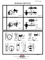
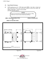
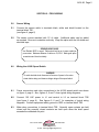
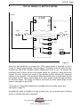
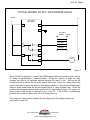
A102-05, Page 1
PCS
PROCESS CONTROL SYSTEMS
952-361-3026
(Fax) 952-368-4129
TM
PROCESS CONTROL SYSTEMS, INC.
327 LAKE HAZELTINE DRIVE, CHASKA, MN 55318
800-328-0738
TM
MAXIGARD A1000
SPEED SWITCH
Introduction
The Maxigard A1000 speed switch is designed to monitor the rotation of critical driven
shafts. The switch is precision built of quality material and completely factory tested to
insure long life and trouble free operation.
Principle of Operation
The Maxigard A1000 speed switch is supplied with a non-contacting sensor and magnetic
target. The sensor signal is not impaired by buildup of dust or any other foreign material
on the magnet disc or sensor. This switch is designed to detect under speed or over speed
of the monitored shaft. The A1000 has one adjustable set point and a built in power-up
time delay of approximately 7 seconds which allows machinery controlled through the
motor starter circuit to reach the set point during start-up. The delay activates on
power-up only and can be disabled with a field selectable jumper pin configuration. When
properly installed and calibrated, in the event of a power failure or loss of sensor signal the
relay will de-energize and put the switch into an alarm condition.
Components
THE A1000 SPEED SWITCH INCLUDES:
z
4“ MAGNET DISC (OTHER OPTIONAL MAGNETIC TARGETS AVAILABLE)
z
SENSOR WITH 10’ OF CABLE AND MOUNTING BRACKET
z
A1000 SPEED SWITCH CIRCUIT BOARDS WITH 10 AMP RELAY
z
NEMA 4 ENCLOSURE
CALL TOLL FREE
PCS
TM
PROCESS CONTROL SYSTEMS
800-328-0738
www.maxigard.com
E-mail: [email protected]
A102-05, Page 2
SECTION 1 - MECHANICAL
1.0
Magnet Disc
1.1
The end of the shaft to be monitored should be square to prevent excessive disc
wobble.
1.2
Center drill and tap the shaft end. (Suggested #21 drill and #10-32NF tap). Bolt the
magnet disc to the end of the shaft. Use “Loc-tite” to keep the bolt and disc tight on
the shaft.
(see figure 1A &1C, page 3).
2.0
Magnet Wrap (optional)
2.1
Separate the two halves of the magnet wrap by loosening the cap screws holding
the two halves together.
2.2
Place both halves of the magnet wrap around the shaft. Re-insert and tighten the
cap screws making sure the wrap is square to the shaft.
(see figure 1B & 1D, page 3).
NOTE
There will be a slight gap between the two halves after tightening. This
gap will not affect the generated signal.
3.0
Mounting the Sensor
3.1
Place the sensor so it is centered directly in front of the magnets in the disc
or optional wrap.
(see figure 1A, 1B, 1C & 1D, page 3).
3.2
The gap setting between the sensor and magnet disc should be approximately
1/8” - 7/8”.
CALL TOLL FREE
PCS
TM
PROCESS CONTROL SYSTEMS
800-328-0738
www.maxigard.com
E-mail: [email protected]
A102-05, Page 3
SENSING METHOD
STANDARD SENSING HEAD & MAGNETIC DISC
STANDARD SENSING HEAD & MAGNETIC WRAP
1/8" to 7/8" GAP
SENSOR
MAGNET
1/8" to 7/8" GAP
MAGNET
SENSOR
MAGNET WRAP
MAGNET DISC
Figure 1A
Figure 1B
XP SENSING HEAD & MAGNETIC DISC
XP SENSING HEAD & MAGNETIC WRAP
1/8" to 7/8" GAP
MAGNET
1/8" to 7/8" GAP
MAGNET
1 5/8"
Figure 1C
Figure 1D
DIMENSIONAL DATA
1/4"
1 1/2"
1 1/2"
4"
10’
5/16"
5/16"
2 1/2"
10’
1 1/2"
1 1/2"
3/4"
2"
1 3/8"
3/4"
1/2" NPS
3/16"
MATERIAL:
RED ANODIZED
ALUMINUM
1/2" NPS
2"
1 3/8"
STANDARD SENSING HEAD AND MOUNTING BRACKET
STANDARD MAGNET DISC
2 1/2"
MATERIAL:
PVC
NEMA 4X SENSING HEAD AND MOUNTING BRACKET
3"
1 1/2"
1 1/2"
15/16"
1 1/2"
2"
D"+3"
5/8"
5/8"
5/16" X 1"
1" 2 1/2"
4"
D"
7/8"
10’
OPTIONAL MAGNET WRAP
XP SENSING HEAD AND MOUNTING BRACKET
Figure 2
PCS
PROCESS CONTROL SYSTEMS
TM
CALL TOLL FREE
800-328-0738
www.maxigard.com
E-mail: [email protected]
A102-05, Page 4
4.0
Speed Switch Enclosure
4.1
A1000 enclosures are UL / CSA listed, rated NEMA 4, dust tight, oil tight and
water tight painted carbon steel construction suitable for indoor and outdoor use.
NEMA 4X fiberglass or stainless steel available.
(see figure 3A & 3B, page 4)
CAUTION
Remove the circuit board from the enclosure before punching or drilling
conduit holes. Be sure to remove all metal chips and filings.
NEMA 4 PAINTED CARBON STEEL
OR
NEMA 4X STAINLESS STEEL
NEMA 4X FIBERGLASS
6 1/2"
4 1/4"
4"
6"
4"
4"
4"
6 1/2"
6 3/4"
7 1/8"
NOTE:
NEMA 4X STAINLESS STEEL ENCLOSURE DOES NOT
INCLUDE SIDE CLAMPS.
Figure 3B
Figure 3A
CALL TOLL FREE
PCS
TM
PROCESS CONTROL SYSTEMS
800-328-0738
www.maxigard.com
E-mail: [email protected]
A102-05, Page 5
SECTION 2 - FIELD WIRING
5.0
Sensor Wiring
5.1
Connect the sensor cable to terminals black, white and shield located on the
terminal block TB1.
(see figure 4, page 6)
5.2
The sensor comes standard with 10’ of cable. Additional cable can be added
as required. Be sure to maintain continuity. Wrap the splice with the foil shield and
electrical tape.
SENSING HEAD CABLE
Use “Belden” #8761 or equal. Cable should not be run in same conduit as
power wires. Maximum distance of cable run 10,000 ft. Make good splice
connections and check continuity.
6.0
Wiring the A1000 Speed Switch
WARNING
To avoid electrical shock disconnect all sources of power to the motor
starter before wiring and observe voltage ratings of the speed switch.
6.1
Power connections and relay connections to the A1000 speed switch are shown
on figure 4, page 6. Also, figures 5, 6 and 7 show typical wiring diagrams.
6.2
Connect 120 VAC power to L1 and neutral to L2 on terminal block TB2
(see figure 4, page 6). See figures 5, 6 and 7 for examples of typical wiring
diagrams. Connect equipment safety ground to GRD on terminal block TB2.
6.3
Make relay connections to terminal block TB2. Normally open contacts are held
closed and the normally closed contacts are held open when the shaft speed
exceeds the calibrated set point.
CALL TOLL FREE
PCS
TM
PROCESS CONTROL SYSTEMS
800-328-0738
www.maxigard.com
E-mail: [email protected]
A102-05, Page 6
4 7/8"
4 1/4"
TB2
120VAC
POWER
CONNECTION
TACH
CALIBRATION
GRD
L2
P3
TB1
L1
SHLD
C
SET
POINT
RELAY
CONTACTS
SLIDE
SWITCH
1
NO 2
SET
POINT
P1
TP
OP
+
4
SENSING
HEAD
CONNECTION
WHT
-
NC 3
C
BLK
4 7/8"
OPTIONAL
TACH
OUTPUT
NO 5
SPEED RANGE
SELECTION
DIP SWITCH
SW1
NC 6
PN 1325 CIRCUIT BOARD
PN 1315 CIRCUIT BOARD
Figure 4
CALL TOLL FREE
PCS
TM
PROCESS CONTROL SYSTEMS
800-328-0738
www.maxigard.com
E-mail: [email protected]
A102-05, Page 7
TYPICAL WIRING TO MOTOR STARTER
TYPICAL WIRING TO MOTOR STARTER
120VAC
N
A1000
L1
L2
GND
STOP
START
OL’s
M
M
1
2
N.O.
COM
N.O. AUX
3
N.C.
4
5
N.O.
COM
6
N.C.
Figure 5
When the start pushbutton is pressed the A1000 speed switch is powered on and a
“power on” delay of approximately 7 seconds begins. During the “power on” delay the relay
contacts are held in the switched position allowing the motor to run. As long as the
monitored shaft is above the set point speed before the “power on” delay period has
expired, the relay contacts will remain in the switched position allowing the monitored
machine to run normally. If the monitored shaft speed slows down or stops below the set
point speed the N.O. relay contact holding in the motor starter contact will open and drop
out the motor starter. The “power on” delay is reset when the motor starter drops out and
power is interrupted to the A1000.
The “power on” delay can be disabled by reconfiguring the time delay jumper pins.
(see figure 8, page 10)
An additional contact is available to sound an alarm horn, turn on another type of warning
device, or interlock with other equipment.
CALL TOLL FREE
PCS
TM
PROCESS CONTROL SYSTEMS
800-328-0738
www.maxigard.com
E-mail: [email protected]
A102-05, Page 8
TYPICAL WIRING TO MOTOR STARTER
120VAC
N
A1000
L1
L2
GND
STOP
START
OL’s
M
M
2
1
N.O.
COM
N.O. AUX
3
N.C.
4
5
N.O.
COM
6
N.C.
Figure 6
When 120 VAC is applied to L1 and L2 the A1000 speed switch is powered on and a “power
on” delay of approximately 7 seconds begins. During the “power on” delay the relay
contacts are held in the switched position allowing the motor to run. As long as the
monitored shaft is above the set point speed before the “power on” delay period has
expired, the relay contacts will remain in the switched position allowing the monitored
machine to run normally. If the monitored shaft speed slows down or stops below the set
point speed the N.O. relay contact holding the motor starter contact will open and drop out
the motor starter. The “power on” delay is reset when power is removed from L1 and L2.
If the A1000 is powered continuously the “power on” delay only occurs at initial power up
and is not available for later restarts. If continuously powered the start pushbutton will need
to be held closed until the monitored shaft reaches operating speed allowing the motor
starter to seal through the motion switch contact.
The “power on” delay can be disabled by reconfiguring the time delay jumper pins.
(see figure 8, page 10)
An additional contact is available to sound an alarm horn, turn on another type of warning
device, or interlock with other equipment.
CALL TOLL FREE
PCS
TM
PROCESS CONTROL SYSTEMS
800-328-0738
www.maxigard.com
E-mail: [email protected]
A102-05, Page 9
TYPICAL WIRING TO PLC OR CONTROL RELAY
120VAC
N
A1000
L1
L2
GND
PLC Input
Module - 120VAC
I:001/01
I:001/02
1
COM
2
N.O.
I:001/03
I:001/04
3
N.C.
4
COM
5
N.O.
CR
6
N.C.
Figure 7
When 120 VAC is applied to L1 and L2 the A1000 speed switch is powered on and a “power
on” delay of approximately 7 seconds begins. During the “power on” delay the relay
contacts are held in the switched position allowing the motor to run. As long as the
monitored shaft is above the set point speed before the “power on” delay period has
expired, the relay contacts will remain in the switched position. If the monitored shaft speed
stops or slows down below the set point speed the N.O. relay contacts open. When the
monitored shaft speed exceeds the set point the N.O. relay contacts close. The “power on”
delay is reset when power is removed from L1 and L2. If the A1000 is continuously
powered the “power on” delay only occurs at initial power up.
The “power on” delay can be disabled by reconfiguring the time delay jumper pins.
(see figure 8, page 10)
CALL TOLL FREE
PCS
TM
PROCESS CONTROL SYSTEMS
800-328-0738
www.maxigard.com
E-mail: [email protected]
A102-05, Page 10
SECTION 3 - CALIBRATION
7.0
A1000 Speed Switch Calibration
7.1
Set the A1000 dip switches for the proper speed range based on the normal
operating speed of the monitored shaft.
(see figure 8, page 10)
SW1
ON
POT P1
SETPOINT
ADJUSTMENT
1 2 3
DIP
SWITCH
TIME
DELAY
JUMPERS
TIME DELAY
JUMPER SETTINGS
ENABLED
POT P3
TACHOMETER
CALIBRATION
(OPERATING
SPEED)
DISABLED
ON
ON
1 2 3
0 to
250
RPM
ON
ON
1 2 3
1 2 3
1 2 3
250 to
600
RPM
600 to
800
RPM
800 to
3000
RPM
ON
1 2 3
3000 to
5000+
RPM
Figure 8
8.0
A1000 Start Delay Configuration
8.1
The A1000 can be configured with or without a 7 second start delay. With the start
delay feature enabled the A1000 relay will automatically energize for 7 seconds
upon power-up. This feature is used to allow the monitored shaft to reach the set
point speed during start up without causing an alarm condition. If the shaft has not
reached the set point speed before the 7 second start delay period has expired, then
the A1000 switch will go into an alarm condition.
With the start delay feature disabled the A1000 relay will not energize until the
monitored shaft speed exceeds the calibrated set point.
(see figure 8, page 10)
CALL TOLL FREE
PCS
TM
PROCESS CONTROL SYSTEMS
800-328-0738
www.maxigard.com
E-mail: [email protected]
A102-05, Page 11
9.0
Calibration with Voltmeter
If the optional tachometer is not supplied with the A1000, a voltmeter can be used to
calibrate the speed switch. Connect the voltmeter leads to terminal block TB1
optional tach output connections (+) and (-).
(see figure 9, page 12)
9.1
To calibrate the operating speed place the slide switch in the operating speed
position (OP). With the machine running at normal operating speed adjust
potentiometer P3 (CCW to increase/CW to decrease) until the voltmeter reads the
recommended DC voltage as shown on table 1.
Table 1
9.2
To calibrate the set point place the slide switch in the set point position (TP).
Calculate the set point value by taking a percentage of the operating speed tach
output voltage from table 1. Adjust potentiometer P1 until you reach the desired set
point on the voltmeter (CW to increase/CCW to decrease). The machine does not
need to be running to make this adjustment.
(see figure 9, page 12)
EXAMPLE
If the operating speed of the monitored shaft is 300 RPM set P3 for a
voltmeter reading of 1.00 VDC while the machine is running at 100%. For
an 80% set point (240 RPM) set P1 for a voltmeter reading of .80 VDC. (1.00
VDC x 80% = .80 VDC)
(see table 1)
CALL TOLL FREE
PCS
TM
PROCESS CONTROL SYSTEMS
800-328-0738
www.maxigard.com
E-mail: [email protected]
A102-05, Page 12
9.3
Return the slide switch to the OP position. The meter will now display the
operating voltage. The set point will still function properly if the slide switch SW1 is
in the TP position.
(see figure 9, page 12)
9.4
A1000 speed switch is now calibrated.
10.0
Calibration with Optional Tachometer
If the optional tachometer is supplied with the A1000, connect the meter as shown
in figure 9, page 12.
10.1
To calibrate the operating speed place the slide switch in the operating speed
position (OP). With the machine running at normal operating speed adjust
potentiometer P3 until the display meter reads 100% (CCW to increase/CW to
decrease).
(see figure 9, page 12)
10.2
To calibrate the set point place the slide switch in the set point position (TP). Adjust
potentiometer P1 until you reach the desired set point on the display meter (CW to
increase/CCW to decrease). The machine does not need to be running to make this
adjustment.
(see figure 9, page 12)
10.3
Return the slide switch to the OP position. The meter will now display the
operating speed. The set point will still function properly if the slide switch SW1 is
in the TP position.
(see figure 9, page 12)
10.4
The A1000 speed switch is now calibrated.
TB2
TACH
CALIBRATION
GRD
L2
P3
OPTIONAL
TACHOMETER
TB1
L1
SHLD
C
SLIDE
SWITCH
1
NO 2
TP
SET
POINT
P1
NC 6
0
WHT
100
OP
+
4
NO 5
SENSING
HEAD
CONNECTION
-
NC 3
C
BLK
RELAY
SPEED RANGE
SELECTION
DIP SWITCH
SW1
% RPM
OPTIONAL
TACH
OUTPUT
POT P1
CW = INCREASE
CCW = DECREASE
POT P3
CCW = INCREASE
CW = DECREASE
Figure 9
PCS
PROCESS CONTROL SYSTEMS
TM
CALL TOLL FREE
800-328-0738
www.maxigard.com
E-mail: [email protected]
A102-05, Page 13
SPARE PARTS LIST
Part No.
Description
1315
1325
1129
1130
1132
1134
1136
1320
A1000 Power Supply Circuit Board Without Relay
Low Set Point Circuit Board
Standard Sensor With 10’ Cable
Mounting Bracket With Jam Nuts
Explosion Proof Sensor With 10’ Cable
Mounting Bracket
4” Magnet Disc
Relay DPDT - 10 AMP @ 120 VAC
LIMITED WARRANTY
Process Control Systems, Inc. will repair or replace, at their option, F.O.B. factory,
any part or unit which proves to be defective in material or workmanship within five
years of purchase date, provided that part of the unit was installed and operated as
recommended, to be established by examination of the part or unit at the factory.
Goods returned under warranty must be shipped prepaid to the factory and
accompanied by the serial number, description of defect, order number and date of
purchase.
This warranty shall not apply to any Maxigard TM product which shall have been
repaired or altered outside of the Process Control Systems factory or has been
subject to misuse, negligence or accident.
Process Control Systems, Inc. warrants its products, but not their application, and
shall not be liable for any incidental or consequential damages incurred through the
use or loss of use of a Process Control Systems product. No representatives or
other person is authorized or permitted to make any warranty or assume for this
company any liability not strictly in accordance with this guarantee.
There is no further warranty either expressed or implied beyond that set forth
herein.
CALL TOLL FREE
PCS
TM
PROCESS CONTROL SYSTEMS
800-328-0738
www.maxigard.com
E-mail: [email protected]