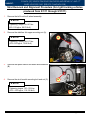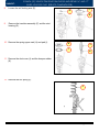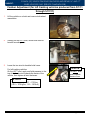
1
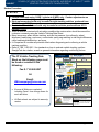
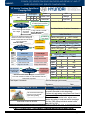
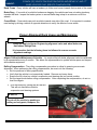
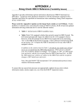
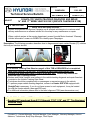
GROUP CAMPAIGN Technical Service Bulletin SUBJECT DATE SEPTEMBER, 2011 NUMBER 11-01-030 MODEL(S) SONATA (YF) SONATA (YF) VEHICLE TRACKING DIAGNOSIS AND REPAIR 16” AND 17” WHEEL VEHICLES ONLY (SERVICE CAMPAIGN # 928) IMPORTANT *** Dealer Stock and Retail Vehicles *** Dealers must perform this Service Campaign on all affected vehicles prior to customer retail delivery and whenever an affected vehicle is in the shop for any maintenance or repair. When a vehicle arrives at the service department, access Hyundai Motor America’s “Warranty Vehicle Information” screen via WEBDCS to identify open Campaigns. Description: The following procedure describes how to diagnose and repair certain Sonata (YF) vehicles that may not track as desired. NOTE The Vehicle Tracking Data Sheet on page 4 of this TSB is REQUIRED to be completed, then either faxed to 714-965-5097, or emailed to [email protected]. Perform road tests using CASE 1 criteria at 40 MPH only. Camber adjustments are based on case 1 tracking results. Dealers and Sublet Vendors must adhere to the vehicle tracking diagnosis and repair flowchart provided on the Vehicle Tracking Data Sheet. Test drives should be completed with no passengers or excessive cargo in the vehicle. To perform proper vehicle tracking diagnosis, access to a Hunter GSP 9700 equipped with StraightTrak is necessary. If you do not have access to such equipment, it may be located through the Hunter website (www.gsp9700.com). For additional information please refer to the latest alignment TSB (www.hmaservice.com). Applicable Vehicles: 2.4L and 2.0T, does not include HEV Sonatas (YF) produced from 5/1/11 through 7/31/11 (16” and 17” Tire Equipped Vehicles Only) Circulate To: General Manager, Service Manager, Parts Manager, Warranty Manager, Service Advisors, Technicians, Body Shop Manager, Fleet Repair SONATA (YF) VEHICLE TRACKING DIAGNOSIS AND REPAIR 16” AND 17” WHEEL VEHICLES ONLY (SERVICE CAMPAIGN 928) SUBJECT: Parts Information: REMARKS PART NUMBER For 2.4L GLS and Limited vehicles equipped with 16” and 17” wheels and which track right, order these two strut kits. DETAILS 54651-3Q000QQH -For right tracking vehicles produced from 5/1/11 through 5/31/11 -Left strut kit 54661-3Q000QQH Use new nuts when -For right tracking vehicles produced installing new 5/1/11 through 5/31/11 struts, as provided. from -Right strut kit 54699-3Q000QQH 2 camber bolts per kit -For vehicles produced from 6/1/11 QTY Front Strut LH Assembly 1 ea Strut Knuckle Mounting Nuts 2 ea Strut Tower Mounting Nuts 3 ea Strut Top Mount Self-Locking Nut 1 ea Front Strut RH Assembly 1 ea Strut Knuckle Mounting Nuts 2 ea Strut Tower Mounting Nuts 3 ea Strut Top Mount Self-Locking Nut 1 ea Camber Bolt Kit (16mm) 1 ea through 7/31/11 NOTE Do not install the above listed parts on vehicles produced from 5/1/11 through 5/31/11, which track left. Warranty Information: Model Op Code Operation Op Time YF 10CA21R0 Road Test Only 0.3 YF 10CA21R1 Road Test and Correct Off-Center Steering Wheel 0.9 YF 10CA21R2 StraightTrak + 2 Road Tests 1.1 YF 10CA21R3 StraightTrak, Adjust Camber, Alignment + 3 Road Tests (left-tracking vehicles) 2.6 YF 10CA21R4 StraightTrak, Install Struts, Alignment + 3 Road Tests (right-tracking vehicles) 4.1 YF 10CA21R5 StraightTrak, Install Camber Bolts, Alignment + 3 Road Tests 3.0 NOTE Submit claim on Campaign Claim Entry Screen. TSB #: 11-01-030 Page 2 of 21 SUBJECT SONATA (YF) VEHICLE TRACKING DIAGNOSIS AND REPAIR 16” AND 17” WHEEL VEHICLES ONLY (SERVICE CAMPAIGN 928) SUBJECT Service Procedure: NOTES Perform road tests using CASE 1 criteria at 40 MPH only. Camber adjustments are based on case 1 tracking results. See page 16 for details. Strut replacements should only be made for right-tracking vehicles, produced from 5/1/11 through 5/31/11. Camber bolts installation should only be made for vehicles produced from 6/1/11 through 7/31/11. When a vehicle is received with a tracking condition the service writer should document the customer comments using the Vehicle Tracking Data Sheet. Many issues may affect vehicle tracking, such as tire pressure, tire uniformity, wheel alignment, brake drag, road crown, cross winds, spring sag resulting in ride height differences, cargo load/weight distribution, and more. It is important to consider all potential effects when diagnosing and confirming a vehicle tracking condition. Refer to TSB 11-SS-001-1 for standards on how to evaluate vehicle tracking, perform StraightTrak tire rotation, as well as general information regarding contributing factors. The YF Vehicle Tracking Data Sheet on the following page must be faxed or emailed to the following: YF Vehicle Tracking Data Sheet Campaign 928 Use Op Code: 10CA21R0 OK Vehicle Tracks Tracks Straight 1. Align Vehicle & set ASP Stg Wheel Left or Right Aligner Make/Model:______ Off Center Calibration Date:_________ Use Hunter GSP9700 StraightTrak feature to measure and arrange all wheel/tire assemblies for least lateral force configuration. Calibration Date:__________ OR Road Test *No Passengers* D 2 Wheel Toe Adjust Prod Date: Customer Comments: Tire Wear/Vehicle Condition Comments: B Initial Test Drive PASS / NO PASS Case # 1 Use Op Code: 10CA21R1 Email: [email protected] Tracks Left PASS / NO PASS Ensure all fields are completed including Case 1 lane change times for each test drive. Tracks Right 1. Loosen struts, push/pull knuckle, retighten. 2. Align and set ASP. 1. Replace struts. 2. Align and set ASP. 6/1 ~ 7/31 1. Install camber bolts. 2. Align and set ASP. 1. Install camber bolts. 2. Align and set ASP. OK Road Test *No Passengers* OK Use Op Code: 10CA21R4 OR 10CA21R5 Vehicle Does Not Track Straight - Contact Hyundai Technical Assistance Hotline at 1-800-325-6604 with this Data Sheet completed. All Data sheets are subject to warranty review. Initial Front Rear Camber Caster N/A Toe Final Front Rear Camber Caster N/A Toe Case # 1 MPH 40 Time ___ L/ R Signature:___________________ Date:______ Use minimal throttle input and do not vary throttle input during testing 6 seconds or less at 40 MPH TSB #: 11-01-030 LEFT / RIGHT Time ______sec Service Manager (print name):______________ Final Repair Comments: Road Test Case #1 – 3.3 ft MPH 40 Alignment Readings (degrees): D 5/1 ~ 5/31 Use Op Code: 10CA21R3 OR 10CA21R5 LEFT / RIGHT Time ______sec C Tire Lateral Force (from Straight Trak) Case # 1 Prod Date MPH 40 Before: ____lbs L/R After: ____lbs L/R Use Op Code: 10CA21R2 OK VIN: Mileage: Technician: Explain tire pressure impact on vehicle pull to customer Road Test *No Passengers* B A Date: Dealer Code: LF RF LR RR *Set Tire Pressure* C Fax #: 714-965-5097 As Received Tire Pressure Record customer comments and vehicle data A Repair Procedure Notes •All campaign vehicles must be road tested and the results recorded on this data sheet. •Perform all road testing using Road Test Case #1 criteria, at 40 MPH. •For vehicles with camber bolts, adjust cross camber according to road test results (see page 16 of the TSB). Keep individual camber within spec (-0.5 0.5 ). Page 3 of 21 SONATA (YF) VEHICLE TRACKING DIAGNOSIS AND REPAIR 16” AND 17” WHEEL VEHICLES ONLY (SERVICE CAMPAIGN 928) SUBJECT: YF Vehicle Tracking Data Sheet Campaign 928 As Received Tire Pressure Record customer comments and vehicle data A LF RF LR RR *Set Tire Pressure* C Mileage: Technician: Prod Date: Use Op Code: 10CA21R0 OK Vehicle Tracks Tracks Straight 1. Align Vehicle & set ASP Stg Wheel Left or Right Aligner Make/Model:______ Off Center Calibration Date:_________ Use Hunter GSP9700 StraightTrak feature to measure and arrange all wheel/tire assemblies for least lateral force configuration. Calibration Date:__________ Road Test *No Passengers* D 2 Wheel Toe Adjust Customer Comments: Tire Wear/Vehicle Condition Comments: B Initial Test Drive PASS / NO PASS Case # 1 Use Op Code: 10CA21R1 Tracks Left PASS / NO PASS Tracks Right 1. Loosen struts, push/pull knuckle, retighten. 2. Align and set ASP. 1. Replace struts. 2. Align and set ASP. 6/1 ~ 7/31 1. Install camber bolts. 2. Align and set ASP. 1. Install camber bolts. 2. Align and set ASP. OK Road Test *No Passengers* OK Use Op Code: 10CA21R4 OR 10CA21R5 MPH 40 LEFT / RIGHT Time ______sec Alignment Readings (degrees): D 5/1 ~ 5/31 Use Op Code: 10CA21R3 OR 10CA21R5 Time ______sec Before: ____lbs L/R After: ____lbs L/R Case # 1 Prod Date MPH 40 LEFT / RIGHT C Tire Lateral Force (from Straight Trak) Use Op Code: 10CA21R2 OK VIN: Dealer Code: Explain tire pressure impact on vehicle pull to customer Road Test *No Passengers* B A Date: Initial Front Rear Camber Caster N/A Toe Final Front Rear Camber Caster N/A Toe Vehicle Does Not Track Straight - Contact Hyundai Technical Assistance Hotline at 1-800-325-6604 with this Data Sheet completed. Case # 1 MPH 40 Time ___ L/ R Service Manager (print name):______________ Final Repair Comments: Signature:___________________ Date:______ Road Test Case #1 – 3.3 ft Repair Procedure Notes Use minimal throttle input and do not vary throttle input during testing 6 seconds or less at 40 MPH •All campaign vehicles must be road tested and the results recorded on this data sheet. •Perform all road testing using Road Test Case #1 criteria, at 40 MPH. •For vehicles with camber bolts, adjust cross camber according to road test results (see page 16 of the TSB). Keep individual camber within spec (-0.5 0.5 ). ***THIS COMPLETED DATA SHEET IS REQUIRED TO BE SUBMITTED BY: FAX (714-965-5097) OR EMAIL ([email protected])*** TSB #: 11-01-030 Page 4 of 21 SUBJECT SUBJECT SONATA (YF) VEHICLE TRACKING DIAGNOSIS AND REPAIR 16” AND 17” WHEEL VEHICLES ONLY (SERVICE CAMPAIGN 928) YF Sonata 2.4 and 2.0T Alignment Specifications, 16” and 17” Wheels Item Camber Cross Camber Caster Toe, Total Toe, Individual Front -0.5° ± 0.5° 0.0° ± 0.5° 4.44° ± 0.5° 0.16° ± 0.2° 0.08° ± 0.1° Rear -1.0° ± 0.5° ----0.17° ± 0.2° 0.085° ± 0.1° Factors that Influence Vehicle Tracking Vehicle drift or pull can be attributed to several factors. Understanding what can affect it is imperative for anyone repairing a vehicle with a tracking condition. Air pressure - Low front tire pressure can cause a vehicle to track towards that tire. Alignment Camber - A vehicle will track towards the side with more positive front camber. Caster - A vehicle will tend to track towards the side with less positive caster. Steering Axis Inclination (SAI) - The angle formed by the line drawn through the steering pivot axis and a line at true vertical when viewed from the front of the vehicle. SAI is designed into a vehicle’s suspension and aids straight-line stability. This angle can be measured by the alignment machine. For Hunter units, it is measured during the caster sweep process. It is useful for checking for damaged components when the SAI difference between left and right sides is more than 1 degree. If SAI is lower on one side of the vehicle it may indicate a bent lower control arm. If SAI is higher on one side of the vehicle it may indicate damage to the upper strut mount. Thrust angle - This is the direction the rear axle is pointing as a result of the rear toe angles and results in the steering wheel being off-center. To avoid this situation, rear camber and toe should be adjusted before the front when performing a four wheel alignment. After the rear is set, center the steering wheel, lock it in place, then adjust the front camber, caster, and toe (if applicable). Tires - Tires can have significant effect on vehicle tracking. Arranging tires on a vehicle according to StraightTrak can greatly improve or eliminate a vehicle tracking condition. Tires contribute to vehicle tracking in the following ways: Ply steer - Ply steer is an inherent characteristic in a tire which results in a lateral force as the tire rolls. Rotating the tires may aid in cancelling out the effects of ply steer. Conicity - Tire conicity refers to the shape of the tire, and how cone-shaped it is. This can influence vehicle tracking. Conicity can be present in a new tire due to manufacturing, or in a used tire due to camber wear. Weight - The amount of weight and where the weight is placed alters a vehicle’s alignment angles, thus changing the tracking tendency. It is important to consider this when diagnosing a vehicle tracking condition. TSB #: 11-01-030 Page 5 of 21 SONATA (YF) VEHICLE TRACKING DIAGNOSIS AND REPAIR 16” AND 17” WHEEL VEHICLES ONLY (SERVICE CAMPAIGN 928) SUBJECT: Road Crown - Every vehicle will have a tendency to follow road crown towards the low side of the crown. Brake Drag - If one side of a vehicle’s brakes are dragging, the vehicle can have a tracking tendency towards that side. Inspect the brake system to ensure brake drag is kept to a minimum on all four wheels. Cross Winds - Cross winds can push a vehicle towards one side of the road. It is important to conduct road testing by driving a vehicle in opposite directions to verify the effects of cross winds. Proper Alignment Rack Usage and Maintenance NOTE These tips apply to Hunter Engineering alignment racks and wheel balancers that feature StraightTrak. It is imperative that the following items be followed to ensure accurate alignment readings. Aligner Calibration/Maintenance Schedule - It is required that all dealer alignment racks be calibrated by a representative every 6 months. This allows the representative to update vehicle specs and inspect and maintain equipment. Rolling Compensation - The rolling compensation procedure is critical to ensuring an accurate alignment. When performing the rolling compensation, be sure to do the following: Set tire pressure to factory specification. Verify that the vehicle is not excessively loaded. Remove any heavy items. Ensure the lift is level so vehicle’s suspension and steering are in a neutral position. Set the target levels before rolling compensation. After completing the compensation, do not relevel the targets. Roll the vehicle by turning the left rear tire. This will not disturb the vehicle’s suspension and steering systems. NOTE Do not roll the vehicle by pushing or pulling on body parts, bumpers, etc. TSB #: 11-01-030 Page 6 of 21 SUBJECT SUBJECT SONATA (YF) VEHICLE TRACKING DIAGNOSIS AND REPAIR 16” AND 17” WHEEL VEHICLES ONLY (SERVICE CAMPAIGN 928) Ensure the pins are in the slip plates, and the turnplate bridge is flush with the rolling surface to minimize the vehicle’s suspension movement. Slip Plates - The slip plates of a Hunter alignment rack are designed to move smoothly and freely to provide accurate measurements. Before driving a vehicle onto the rack, check that they move freely and do not bind. Periodically clean the area underneath the slip plates by blowing compressed air through to remove any debris. If this does not free a binding plate, contact your local Hunter representative for cleaning and lubrication recommendations. StraightTrak LFM feature - StraightTrak is an optional feature for Hunter’s GSP9700 wheel balancer. This feature measures lateral force of a tire due to ply steer, conicity, and other issues which may contribute to vehicle tracking. This is a very useful tool for vehicles with a tracking condition. TSB #: 11-01-030 Page 7 of 21 SUBJECT: SONATA (YF) VEHICLE TRACKING DIAGNOSIS AND REPAIR 16” AND 17” WHEEL VEHICLES ONLY (SERVICE CAMPAIGN 928) Use StraightTrak to arrange the 4 wheel/tire assemblies of a vehicle in a configuration which will result in the least tire pull force by doing the following: 1. Remove all wheel/tire assemblies from the vehicle. 2. Balance the front left assembly on the Hunter GSP9700 with StraightTrak feature. An icon located in the lower right corner will show whether or not StraightTrak is enabled. 3. After balancing, press the tire tag button located at the bottom right of the screen to assign a number to that assembly. Label the assembly accordingly with a tag or chalk mark. 4. Continue to balance and tag all four assemblies. After all are completed, the screen will show tire positioning and the effect on tire pull or vibration. The purple horizontal arrow at the top of the screen shows overall pulling force and direction due to tires. The brown vertical arrows above each tire show the RFV of each assembly. Select “Show Least Pull” for lowest tire effects on pulling. Select “Show Least Vibration” for the smoothest ride. TSB #: 11-01-030 Page 8 of 21 SUBJECT SUBJECT SONATA (YF) VEHICLE TRACKING DIAGNOSIS AND REPAIR 16” AND 17” WHEEL VEHICLES ONLY (SERVICE CAMPAIGN 928) Select “Show Alternate Placements” for other configurations. TSB #: 11-01-030 Page 9 of 21 SUBJECT: SONATA (YF) VEHICLE TRACKING DIAGNOSIS AND REPAIR 16” AND 17” WHEEL VEHICLES ONLY (SERVICE CAMPAIGN 928) Strut Removal and Alignment Procedure (for right tracking vehicles produced from 5/1/11 through 5/31/11) 1. Remove the left front tire & wheel assembly. NOTE Tightening Torque: 89-107 Nm (9.0-11.0 kgf.m, 66-79 lb-ft) 2. Remove the stabilizer link upper mounting nut (A). A NOTE Tightening Torque: 99-117 Nm (10.0-12.0 kgf.m, 73-86 lb-ft) 3. Remove the speed sensor and brake hose brackets (B). 4. Remove the strut knuckle mounting bolt and nut (C). B NOTE Tightening torque: 157~176 N.m (16.0 ~18.0 kgf.m, 116-130 lb-ft) C TSB #: 11-01-030 Page 10 of 21 SUBJECT SUBJECT 5. SONATA (YF) VEHICLE TRACKING DIAGNOSIS AND REPAIR 16” AND 17” WHEEL VEHICLES ONLY (SERVICE CAMPAIGN 928) Loosen the left front strut upper mounting nuts and remove the strut & spring assembly. NOTE Tightening torque: 45 ~ 58 N.m (4.5 ~ 6.0 kgf.m, 33 ~ 43 lb-ft) 6. Set the removed strut & spring assembly into the SST (09546-26000) as shown on the photo. 7. Press down the coil spring (D). CAUTION Only compress the spring enough to confirm the bottom coil is no longer in contact with the spring seat. D TSB #: 11-01-030 Page 11 of 21 SUBJECT: 8. SONATA (YF) VEHICLE TRACKING DIAGNOSIS AND REPAIR 16” AND 17” WHEEL VEHICLES ONLY (SERVICE CAMPAIGN 928) Loosen the self locking nuts (E). F E G 9. Remove the insulator assembly (F) and the strut bearing (G). 10. Remove the spring upper seat (H) and pad (I). H J I K 11. Remove the dust cover (J) and the bumper rubber (K). 12. Remove the coil spring (L). L TSB #: 11-01-030 Page 12 of 21 SUBJECT SUBJECT SONATA (YF) VEHICLE TRACKING DIAGNOSIS AND REPAIR 16” AND 17” WHEEL VEHICLES ONLY (SERVICE CAMPAIGN 928) 13. Assemble the strut assemblies by reinstalling all removed parts in reverse order of removal. Do not reuse original strut mounting nuts (knuckle, strut tower, and strut top). Use the new ones provided. NOTE Tightening torque for strut top nut: 58.8~68.6 Nm (6~7 kgf.m, 43.4~50.6 lb-ft) TSB #: 11-01-030 CAUTION Make sure the notch on the strut rod matches up with the notch in the spring upper seat during re-installation. Page 13 of 21 SUBJECT: SONATA (YF) VEHICLE TRACKING DIAGNOSIS AND REPAIR 16” AND 17” WHEEL VEHICLES ONLY (SERVICE CAMPAIGN 928) Camber Adjustment (for left tracking vehicles produced from 5/1/11 through 5/31/11) 1. Lift the vehicle on a hoist and remove both wheel assemblies. 2. Starting on the LEFT side, loosen both strut-toknuckle mounting nuts. 3. Leave the two strut-to-knuckle bolts loose. For left-tracking vehicles: On the LEFT strut, apply and hold pressure to the top of the brake rotor towards the center of the vehicle, then tighten all strut fasteners. NOTE For LEFT strut, push towards center of car. NOTE Tightening torque: 157 ~ 176 N.m (16.0 ~ 18.0 kgf.m, 116 ~ 130 lb-ft) TSB #: 11-01-030 Page 14 of 21 SUBJECT SUBJECT 4. SONATA (YF) VEHICLE TRACKING DIAGNOSIS AND REPAIR 16” AND 17” WHEEL VEHICLES ONLY (SERVICE CAMPAIGN 928) Repeat steps 2-3 for the RIGHT strut, with the following exception: Apply and hold pressure in the opposite direction (pull the top of brake rotor towards outside of vehicle), then tighten all strut fasteners. NOTE For RIGHT strut, pull towards outside of car. NOTE Tightening torque: 157 ~ 176 N.m (16.0 ~ 18.0 kgf.m, 116 ~ 130 lb-ft) Camber Adjustment (Service Camber Bolt, for vehicles produced from 6/1/11 through 7/31/11) 1. Lift the vehicle on a hoist and remove wheel assembly. 2. Remove upper strut-to-knuckle mounting nut and bolt. TSB #: 11-01-030 Page 15 of 21 SONATA (YF) VEHICLE TRACKING DIAGNOSIS AND REPAIR 16” AND 17” WHEEL VEHICLES ONLY (SERVICE CAMPAIGN 928) SUBJECT: 3. Install a service camber bolt in the upper strut-toknuckle hole. Ensure the washer tab is facing the correct direction, according to the desired camber adjustment range. NOTE For more positive camber adjustment, install the bolt with the washer tab facing towards the wheel. Install the camber bolt with the washer tab facing the engine (inside) for more negative camber adjustment (right strut shown). For more negative camber adjustment, install the bolt with the washer tab facing towards the engine. Install the camber bolt with the washer tab facing the wheel (outside) for more positive camber adjustment. 4. With both the upper (camber bolt) and lower (factory bolt) strut-to-knuckle bolts slightly loose, turn the camber bolts to adjust the camber to the desired value. Adjust the cross camber by the amount shown below, for the tracking result range listed: Tracking Result* (Case Cross camber change (left #1, 40 mph) camber minus right camber) 1 ~ 4 seconds 0.5° ~ 1.0° 4 ~ 6 seconds 0.0° ~ 0.5° IMPORTANT The suggested cross camber adjustment values listed in the table are based on the results of Case #1, 40 MPH road testing. The values listed in the table are for cross-camber change, not absolute cross camber. The cross camber value is to be achieved by adjusting the left and right camber values, staying within the individual camber specification tolerance range (-0.5° ± 0.5°). For vehicles which track right, adjust the cross camber value more positive. For vehicles which track left, adjust the cross camber value more negative. Some vehicles may need additional adjustment beyond the suggested range to pass the road test. Tighten both nuts (top and bottom) when the desired camber is achieved. NOTE Tightening torque: 157 ~ 176 N.m (16.0 ~ 18.0 kgf.m, 116 ~ 130 lb-ft) TSB #: 11-01-030 Page 16 of 21 SUBJECT SUBJECT SONATA (YF) VEHICLE TRACKING DIAGNOSIS AND REPAIR 16” AND 17” WHEEL VEHICLES ONLY (SERVICE CAMPAIGN 928) ASP Calibration Procedure Using the GDS a) Choose VIN on the initial screen. b) Enter the vehicle information by pressing the VIN Auto Detect button, entering the vehicle's VIN or selecting the vehicle model, model year, engine/fuel type and EPS as the system and then click OK. c) Select Option Treatment on the initial screen after entering the vehicle information. d) Select ASP Calibration. TSB #: 11-01-030 Page 17 of 21 SUBJECT: SONATA (YF) VEHICLE TRACKING DIAGNOSIS AND REPAIR 16” AND 17” WHEEL VEHICLES ONLY (SERVICE CAMPAIGN 928) e) Read the prompt screen and select OK when ready. f) Ensure the ignition and engine are ON and that the steering wheel is centered with the front wheels pointed straight ahead. TSB #: 11-01-030 Page 18 of 21 SUBJECT SUBJECT SONATA (YF) VEHICLE TRACKING DIAGNOSIS AND REPAIR 16” AND 17” WHEEL VEHICLES ONLY (SERVICE CAMPAIGN 928) g) Select OK. h) Turn the ignition OFF, wait 15 seconds, then turn the ignition ON again. Check in current data that the steering angle sensor is within ±5 degrees. TSB #: 11-01-030 Page 19 of 21 SONATA (YF) VEHICLE TRACKING DIAGNOSIS AND REPAIR 16” AND 17” WHEEL VEHICLES ONLY (SERVICE CAMPAIGN 928) SUBJECT: SERVICE CAMPAIGN NOTIFICATION Dear 2011 or 2012 Sonata Owner: A small number of owners of 2011 and 2012 Sonata vehicles equipped with factory-installed 16-inch or 17-inch wheels and tires may have experienced dissatisfaction with vehicle tracking. Hyundai has issued a service campaign to correct this condition on those vehicles that may be affected. This letter provides you with information about the service campaign. What is the purpose of the service campaign? Some 2011 and 2012 Sonata vehicles equipped with factory-installed 16-inch or 17-inch wheels and tires may not track as the driver desires without slight/minor steering wheel correction when driving on straight, flat roads. Hyundai has developed a service procedure to improve the tracking of vehicles affected by this condition. What vehicles does this apply to? This service campaign applies only to 2011 and 2012 model year Sonatas equipped with factory-installed 16-inch and 17-inch wheels and tires that were manufactured beginning on May 1, 2011 through July 31, 2011 and that do not track straight without steering wheel correction on straight, flat roads. If your vehicle tracks straight, you do not need to have this service campaign performed. What will Hyundai do? If your vehicle does not track as you desire on straight, flat roads, your Hyundai dealer will check your vehicle’s wheel alignment and how your vehicle tracks. If necessary, your Hyundai dealer will install new front suspension struts and/or camber bolts, update the Electronic Power Steering software, and perform a wheel alignment procedure at no charge to you. What should you do? Please schedule an appointment at your convenience to take your vehicle to your Hyundai dealer. When you make an appointment, please confirm the dealer’s schedule to determine how much time will be required to perform the work so you may plan appropriately. It may be necessary to leave your vehicle at the dealer overnight. To help facilitate the process, you can schedule an online appointment. Please visit Hyundai.com, click on “Find a Dealer” and input your zip code. When your preferred dealer appears, click on “Schedule Service” under their address. TSB #: 11-01-030 Page 20 of 21 SUBJECT SUBJECT SONATA (YF) VEHICLE TRACKING DIAGNOSIS AND REPAIR 16” AND 17” WHEEL VEHICLES ONLY (SERVICE CAMPAIGN 928) o If you already have a log-on and password for online scheduling, enter them here, click on “Log In”, then click on “Repair”. Select “Campaign” and in the “Repair Service” box, enter the code: SONATA-TR02 and click on “OK”. Follow the instructions on the next screens to schedule your appointment. o If you do not have a log-on and password, complete the information under “New Customer” and click on “Repair”. Select “Campaign” and in the “Repair Service” box, enter the code: SONATA-TR02 and click on “OK”. Follow the instructions on the next screens to schedule your appointment. If your preferred dealer does not have a link to schedule service online, please contact them via phone to schedule an appointment. What if you have other questions? If you have any questions related to this service campaign, please contact the Hyundai Customer Connect Center at 1-800-633-5151 or [email protected]. We thank you for your purchase of your Sonata and hope for your continued satisfaction as a Hyundai owner. Hyundai Motor America TSB #: 11-01-030 Page 21 of 21