1
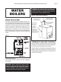
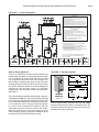
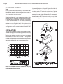
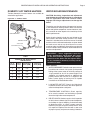
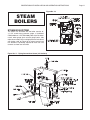
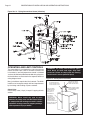
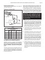
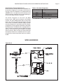
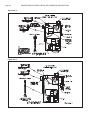
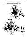
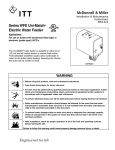
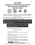
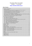
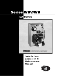
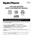
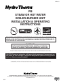
HPB9-10
PB
STEAM OR HOT WATER
BOILER-BURNER UNIT
INSTALLATION & OPERATING
INSTRUCTIONS
ENERGY STAR
DESIGNED AND TESTED ACCORDING TO A.S.M.E. BOILER AND PRESSURE
VESSEL CODE, SECTION IV FOR A MAXIMUM ALLOWABLE WORKING PRESSURE OF:
15 PSI STEAM OR 40 PSI WATER.
TO INSTALLER
NOTE: READ THESE INSTRUCTIONS CAREFULLY. THEY WILL
SAVE YOU VALUABLE TIME WHEN ASSEMBLING THE BOILER.
THESE INSTRUCTIONS TO BE LEFT WITH THE BOILER FOR REFERENCE PURPOSES.
CAUTION: Do not use automotive anti-freeze in boiler waterways. If necessary to use
anti-freeze, be sure to employ a preparation designed for hydronic heating systems
such as ethylene or propylene glycol.
CONSUMER, RETAIN THESE INSTRUCTIONS FOR FUTURE REFERENCE PURPOSES.
IN UNITED STATES: 260 NORTH ELM ST., WESTFIELD, MA 01085 • (413) 564-5515 FAX (413) 568-9613
IN CANADA: 7555 TRANMERE DRIVE, MISSISSAUGA, ONTARIO L5S 1L4 • (905) 672-2991 FAX (905) 672-2883
www.hydrotherm.com
9/12
Page 2
PB SERIES BOILER INSTALLATION AND OPERATING INSTRUCTIONS
CONTENTS
General ....................................................................... 2
Codes, Rules and Regulations ................................... 2
Boiler Location ............................................................ 2
Chimney and Breeching ............................................. 3
Combustion and Ventilation ........................................ 3
Inspection ................................................................... 4
Jacket Assembly ......................................................... 4
Cleanout Cover Plates ................................................ 4
Boiler Trim ......................................... (Water) 5, (Steam) 11
Thermostat and Limit Controls .......... (Water) 5, (Steam) 12
Piping Connections ............................ (Water) 6, (Steam) 11
Circulators .................................................................. 8
Domestic Hot Water Heaters ...................................... 9
Filling the System .............................. (Water) 8, (Steam) 14
Boiler Maintenance .......................(Water) 9-10, (Steam) 15
Steam Boiler Cable Installation ................................ 16
Replacement Parts ................................................... 19
Start-Up Checklist .................................................... 21
Burner Specifications ............................................... 22
Warranty ................................................................... 25
GENERAL
The PB Series boiler-burner unit is a wet-base, vertical
flue, low pressure, sectional, cast iron steam or hot
water heating boiler. It is rated for natural draft firing with
-0.02" WC over the fire draft. Boilers are available as
three to six sections in length with burner and controls
supplied a completely packaged boiler.
The ports between sections are provided with a special
hydronic seal which is resistant to petroleum products.
The flue gas seal between sections is accomplished by
the use of fiberglass rope rated at 1000°F.
Packaged units are hydrostatically tested for the
maximum working pressures.
An insulated metal jacket is furnished to both enhance
the units looks and to minimize any heat loss. A
full access cleanout cover for cleaning vertical flue
passages is on the left hand side of the boiler and is
accessible by removing the left hand cleanout access
jacket panel.
IMPORTANT - Sufficient clearance between the
left side of the boiler and adjacent construction
must be provided to ensure proper access when
cleaning is required!
CODES, RULES AND REGULATIONS
The installation of the boiler, the burner, wiring, controls
and fuel piping must be done in accordance with the
requirements of the local authorities having jurisdiction.
In the absence of local requirements, the following
codes apply:
ANSI/NFPA31 - “Installation of Oil Burning Equipment”
ANSI/NFPA70 - “National Electrical Code”
In Canada the following codes apply:
CSA STD. B149 - Latest Edition.
“Installation Code For Oil Burning Equipment.”
CSA STD. C22.2 No. 0 - Latest Edition.
“General Requirements - Canadian Electrical Code
Part II.”
All completed boilers shall satisfactorily pass the
hydrostatic tests as prescribed by A.S.M.E., Code
Section IV.
1. Steam Boilers – The assembled boiler shall be
subjected to a hydrostatic test of not less than 45
psig.
2. Water Boilers – The assembled boiler shall be
subjected to a hydrostatic test pressure of 60 psig.
3. The required test shall not exceed the test pressure
by more than 10 psig.
PB SERIES BOILER INSTALLATION AND OPERATING INSTRUCTIONS
Page 3
BOILER LOCATION
CHIMNEY AND BREECHING
Boiler should be located on a smooth level concrete
floor or pad close to the chimney to minimize breeching
length. Allow access for boiler cleaning and burner
maintenance.
Attach the smoke hood to the back of the boiler using
the 4 brass machine screws making sure to install the
gasket between the smoke hood and boiler. (Gasket
and hardware located in literature bag.) The 3 and 4
section models are equipped with a 6" smoke hood,
the 5 and 6 section models with a 7" smoke hood. The
boiler must be vented with vent pipe having the same
diameter as the smoke hood collar. Place the flue pipe
over the smoke hood collar and secure it to the collar
with a sheet metal screw.
Figure 1A
The flue pipe should be run to the chimney by the most
direct route, with the minimum number of elbows and
with a slight upward pitch. The pipe should terminate
flush with the inside face of the chimney and should be
sealed in place with insulating cement. The boiler must
be vented to the outdoors by means of a tile lined masonry chimney.
CAUTION - Boiler shall be installed on noncombustible floor only, unless Figure 1A is
followed.
Figure 1B
For energy conservation, the boiler can be vented
directly into a chimney without the use of a barometric
draft control, unless required by code or in instances
where the chimney can develop excessive draft.
Overfire draft greater than -0.05" WC, with the burner
in operation, is excessive (normal draft is -0.02 to -0.04"
WC).
COMBUSTION AND VENTILATION
Normal residential construction usually allows sufficient
air infiltration for combustion. If construction is tight,
consideration should be given for air louvers to the
outside. Local codes or NFPA 31, “Installation of Oil
Burning Equipment”, should be referred to for proper
sizing and design and air supply. In Canada refer to CSA
STD. B149 - latest edition.
WARNING: This boiler must be connected to a
properly sized and constructed chimney or vent
system! Failure to comply with this warning
can result in a fire which could cause extensive
property damage, severe personal injury or
death!
Page 4
PB SERIES BOILER INSTALLATION AND OPERATING INSTRUCTIONS
INSPECTION
CLEANOUT COVER PLATE(S)
Careful inspection should be made of all assemblies
to detect possible damage during shipment. Factory
assembled boilers are hydrostatically tested at the factory
to insure pressure tightness. Before piping connections
are made to the boiler, hydrostatically retest boiler
sections to detect leaks that may have developed from
rough handling during shipment. (Maximum allowable
working pressure of 15 psi steam or 80 psi water)
It is important to maintain the integrity of the gas seal by
careful installation of the cleanout cover plate. Be sure
there is no opening to allow gases to escape.
PACKAGED BOILERS
The “Burner in the Box”
Packaged boilers with “The Burner in the Box” are
shipped on a wood skid with tie down bands and a
wooden crate enclosing the boiler. The boiler is shipped
without the burner being mounted and wired in place.
The burner is shipped and inventoried independently of
the boiler. Burners from Carlin, Beckett and Riello are
available as options. The PB Series boiler is equipped
with a universal harness system utilizing a 6-pin electrical
connector. The harness system has been designed to
allow any of these burners to connect to both steam and
water boilers. The harness system is designed to make
burner replacement and routine servicing quicker and
safer to perform.
Packaged boilers are shipped on a wood skid with tie
down bands and a wooden crate enclosing the boiler
and burner installed.
Remove the protective crate and skid. Set the boiler in
its final location and shim under the feet to make it level
and secure. Adjust the jacket for proper alignment and
support. Refer to Oil Fired Boiler Electrical Diagrams
(PDEWD) for appropriate wiring diagrams.
WARNING: Never attempt to operate the boiler
with the cleanout cover plates removed! Failure
to comply with this warning can result in a fire
which could cause extensive property damage,
severe personal injury or death!
JACKET ASSEMBLY
(ASSEMBLED BLOCKS)
Remove all knockouts that are going to interfere with
your specific installation arrangement. Install the front
panel over the two upper burning mounting plate studs
prior to the installation of the burner mounting plate. Fold
the right side panel at both the front and rear perforated
seams 90° back against the insulation. Slide the front fold
under the front panel and secure with philip head screw.
Lift side panel up slightly to align the slots in jacket with
the bracket holes. Secure with the screws supplied.
Repeat same procedure for the left side panel. Screw
the two folds together at the back of the boiler.
Attach the top panel over the edges of all panels and
secure. The cleanout cover door attaches to the left side
panel by sliding the lower left corner into the slot provided and up over the fold at the top of the opening in the
side panel. Slide the cover back toward the rear of the
boiler until it makes contact with the back of the slot.
Figure 2 – Jacket Assembly
TOP
PANEL
RIGHT SIDE PANEL
FRONT
PANEL
COVER PANEL
LEFT SIDE
PB SERIES BOILER INSTALLATION AND OPERATING INSTRUCTIONS
WATER
BOILERS
WATER BOILER TRIM
The water trim furnished with the boiler consists of a
2-1/2" round temperature pressure gauge and a 30 psig
pressure relief valve. A circulator relay is furnished for
installation in the upper port cover plate or the tankless
heater cover plate as indicated in Figure No. 3. The
installer must furnish and install air removal devices,
expansion tank, automatic air vents, make-up water
pressure reducing valve, isolating valves and other pipe
fittings and equipment necessary for proper operating
system.
Page 5
WARNING: The pressure relief valve discharge
piping must direct all water and vapor away from
personnel. Failure to comply with this warning
could result in severe personal injury!
Figure 4 – Relief Valve Installation
DISCHARGE PIPE SIZE
EQUAL TO VALVE OUTLET.
DO NOT RESTRICT FLOW.
FOR DISCHARGE
PIPING THROUGH
ROOF CONSULT
THE SMITH CO.
SUPPORT DISCHARGE
PIPING SO AS TO AVOID
STRAIN ON VALVE BODY
RELIEF OR SAFETY VALVE.
DO NOT REMOVE RATING
OR WARNING TAGS
DISCHARGE SO
AS TO AVOID
EXPOSURE OF
PERSONS TO HOT
LIQUID OR VAPOR.
LEAVE OPEN END
VISIBLE FOR PERIODIC
INSPECTION FOR SLOW
LEAKAGE OR DRIPS.
Figure 3
THERMOSTAT AND LIMIT CONTROLS
Many jurisdictions require dual limit controls. The boiler
installer must arrange to comply with local requirements
by furnishing and installing any extra controls.
The water boiler is furnished with a Hydrolevel Hydrostat
hydronic relay, which provides high limit low limit and
circulator switching upon signal from a 24 volt thermostat
and LWCO functionality.
Pressure Relief Valve
Install safety relief valve (30 psi) in top 3/4" tapping of
back section.
WARNING: Never install any type of valve
between the pressure relief valve and the boiler!
Failure to comply with this warning can result in
a boiler explosion causing extensive property
damage, severe personal injury or death!
Page 6
PB SERIES BOILER INSTALLATION AND OPERATING INSTRUCTIONS
PIPING
Pumped Bypass
For these systems that may experience condensation,
an additional circulator and balancing valve can be
used to provide a return water temperature blend. This
method works well with systems with multiple zones
with circulators, see Figure 5. The dedicated bypass
circulator provides a strong blending flow without
diminishing the flow available to any heating zone. Any
residentially sized circulator is adequate for this purpose.
The balancing valve allows for adjustment of the return
temperature (see adjustments procedure in Figure 5).
Pump Away Bypass
For systems that use a single circulator to pump away
from the boiler, the bypass should be installed on the
discharge side of the circulator, see Figure 6. Full
temperature water supplies the baseboard distribution
system as before. Half of the circulator’s volume moves
through the bypass, blending and heating the cooler
return water. Again, the cost of installing the bypass is
small and setting it by temperature can be accomplished
with a contact thermometer (see bypass adjustment
procedure Figure 6).
Figure No. 5 – Pumped Bypass
System Purging.
1. Close valve A and C.
2. Attach a short hose to valve D and submerge in bucket
of water. Open Valve D.
3. Manually open the fill valve and use the domestic water
system pressure to purge air from each zone one at a
time. When air bubbles stop flowing from the hose
close valve D.
4. Rest fill valve to automatic fill, and open valves A and C.
Bypass Adjustment Procedure To Maintain Inlet
Te mperature Above Dew Point
T1=Te mp Min=130°F
1. Turn boiler on and close valve A.
2. After steady-state operation, if T1 is less than 130°F
slowly open valve A until T1 climbs to desired operating
temperature above 130°F.
3. Check after system operating temperature has
stabilized. Make final adjustments.
NOTES:
1. Boiler circuit piping must be sized large enough to handle
maximum flow through unit.
2. Boiler pump sized to boiler design flow requirements.
3. All boilers furnished with factory mounted water
temperature/pressuregauge.
4. A plug valve will allow the best flow control for the bypass.
A ball valve may not be suitable and may create noise.
Notice: These drawings show suggested piping configuration
and valving. Check with local codes and ordinances for
specific requirements.
Drain Cock
Backflow-Prevention
Device
Air Vent &
Separator
Expansion Aquastat
Tan k
Thermometer
Pressure
Relief Valve
Check Valve
Pressure
Reducing Valve
Balance Valve
Pump
Ball or Gate
Valve
Page 7
PB SERIES BOILER INSTALLATION AND OPERATING INSTRUCTIONS
Figure No. 6 – Pump Away Bypass
System Purging.
1. Close valve A and C.
2. Attach a short hose to valve D and submerge in bucket of
water. Open Va lve B and D.
3. Manually open the fill valve and use the domestic water
system pressure to purge air from each zone one at a time.
When air bubbles stop flowing from the hose close valve D.
4. Rest fill valve to automatic fill., and open valves A and C.
Bypass Adjustment Procedure To Maintain Inlet
Temperature Above Dew Point
T1=Temp Min=130°F
1. Turn boiler on and open valves A & B.
2. After steady-state operation, if T1 is less than 130°F
slowly close valve B until T1 climbs to desired operating
temperature above 130°F.
3. If T1 is greater than desired operating temperature, slowly
close valve A to adjust to lower desired temperature above
130°F.
4. Check after system operating temperature has
stabilized. Make final adjustments.
NOTES:
1. Boiler circuit piping must be sized large enough to handle
maximum flow through unit.
2. Boiler pump sized to boiler design flow requirements. A
percentage of the pump capacity is used for the bypass blend.
3. All boilers furnished with factory mounted water
temperature/pressure gauge.
4. A plug valve will offer the best flow control for the bypass. A ball
valve may not be suitable and may create noise.
Notice: These drawings show suggested piping configuration
and valving. Check with local codes and ordinances for
specific requirements.
Motorized Valv e
Drain Cock
Backflow-Prevention
Device
Air Vent &
Separator
Expansion
Tank
Aquastat
Thermometer
Reverse Acting Aquastats
There is an alternative for existing systems experiencing
condensation that does not require re-piping the boiler.
It is very effective on single zones high mass systems
with large water volumes and cast iron radiation. This
option utilizes a reverse acting aquastat, one that makes
on temperature rise. Wired in series with the circulator,
this control allows the burner to fire while holding the
circulator off until the boiler reaches an acceptable
temperature. It then starts the system circulation again,
see Figure 7.
The most commonly available reverse acting aquastat is
a Honeywell L4006B. The aquastat should be mounted
in an immersion well directly installed in the boiler. The
use of heat conductive grease, Honeywell part #972545,
in the immersion well is strongly recommended for
fast and accurate temperature response. Set this
adjustable aquastat to make at no less than 130°F.
While this method can cause the circulator to cycle
more frequently, setting the aquastat’s differential to the
maximum 25-30°F will minimize short cycling.
Pressure
Relief Valve
Check Va lve
Pressure
Reducing Valv e
Balance Valve
Pump
Ball or Gate
Valve
Figure No. 7 – Reverse Aquastat
115 volts
reverse
aquastat
N.O.
circulator
24 volts
T
t'stat
T
REVERSE
AQUASTAT
operating
aquastat
SET AT 130° F
N.C.
GV
Each of these bypass solutions also has the added
benefit of increasing circulation in the boiler which will
maximize tankless coil output and increase the accuracy
of temperature sensing controls.
Page 8
PB SERIES BOILER INSTALLATION AND OPERATING INSTRUCTIONS
FILLING THE SYSTEM
Water
Fill the system slowly, while venting air and checking for
leaks. Do not operate the circulator until the system is
full. Run the circulator without firing the burner until all
air has been bled from the system.
When the relief valve is set to operate at 30 psi, the
initial fill pressure should be sufficient to fill the system
to the high point and develop a pressure at that point
so as to prevent the water in the system from boiling
at the maximum operating temperature. Under normal
conditions, a static height of 18-1/2' will require an initial
fill pressure of 12 psi. If using the suggested piping
arrangements, see the system purging instructions with
the diagram.
CIRCULATORS
The Taco 007 and 0010 circulators are suitable for use on
a closed heating system with 30 psig maximum operating
pressure. If a circulator is furnished with the boiler does
not have the required capacity to serve the connected
load, provide an extra zone circulator or change the
circulator to the proper size. Capacity curves for the
circulators are provided in these instructions to permit the
sizes to be checked with the system requirements.
Graph 1
NOTE: The Taco 0010 circulator is rated for 125 psig
maximum operating pressure.
A Special Note to Installers of Water Boiler: All Carlin
and Beckett burners, shipped separately under the
“Burner In The Box” program do not have a jumper wire
installed on the T-T terminals on the primary ignition
control. Water boilers require this jumper in order to
operate. On water boilers the thermostat is connected to
the aquastat relay, on a steam boiler the thermostat will
be connected to the T-T terminals on the primay ignition
control (see Figure No. 8).
Figure No. 8
PB SERIES BOILER INSTALLATION AND OPERATING INSTRUCTIONS
DOMESTIC HOT WATER HEATERS
Tankless domestic hot water heaters are available for
water boiler application.
Figure No. 9 – Tankless Heater
OPERATING CONTROL
TEMPERING VALVE
CHECK VALVE
COLD WATER SUPPLY
TEMPERED HOT
WATER SUPPLY
Table 1
DOMESTIC HOT WATER SUPPLY
WATER BOILER
Firing
Rate
Intermittent
Draw (GPM)
Low
2.50
High
2.50
Low
3.30
4
High
3.30
Low
3.80
5
High
4.50
Low
4.60
6
High
5.00
40° to 140°F temp. rise at 180°F. boiler water.
3
WATER BOILER MAINTENANCE
CAUTION: Servicing, inspection and adjustment
must be done by a trained technician in accordance
with all applicable local and national codes.
Improper servicing or adjustment can damage the
boiler!
The boiler must be cleaned and inspected at least on
a year before each heating season. Make sure that the
burner and ignition components are free from dust, soot,
dirt, corrosion or other deposits that would impair the
boiler’s performance.
C
H
No. of
Sections
Page 9
Continuous
Draw (GPM)
1.75
2.00
2.50
2.90
3.30
3.90
4.00
4.90
Safety checks should include, but not limited to, the
items listed in the Boiler Safety Checklist. This Safety
Checklist is included at the end of the manual. A trained
technician with a calibrated combustion analyzer should
be hired to test and set up the oil burner to assure
maximum safety and efficiency. Consult the manufacturer
of each individual safety control for recommendations for
service and adjustment.
IMPORTANT - These suggestions cover the
boiler maintenance work which will result
in the most efficient operation, the longest
useful life of the boiler and the highest return
on any investment necessary to carry out the
maintenance work.
Water Controls
1. WATER PRESSURE: The boiler water pressure must
be sufficient to maintain a full system and to prevent
boiling of the system water. An initial fill pressure of
12 psi provides for 18-1/2' of system height. Each
additional 2.3' of height requires an additional one
pound pressure. Be sure no air is trapped in the
boiler, system piping or heating units to impede
circulation of the heated boiler water.
2. LOW WATER CUTOFF: Check the Hydrolevel
Hydrostat control to be certain the switch opens on
water level drop below cutoff point.
3. TEMPERATURE CONTROLS: Check regularly
to be sure the controls are functioning to prevent
excessive high boiler water temperature.
4. RELIEF VALVES: Conduct regular visual inspection
of relief valves to detect signs of corrosive deposits,
rust buildup or signs of weeping. It should not weep
or discharge water at normal system pressure.
NEVER try to clean or repair the relief valve! If valve
fails replace it! Replace the valve with a new valve
of proper capacity and pressure setting if defective.
Page 10
PB SERIES BOILER INSTALLATION AND OPERATING INSTRUCTIONS
MAINTENANCE
Heating Surface Cleaning
WARNING: Failure to disconnect all electrical
power to the boiler before cleaning it could
result in a fire or severe personal burn injuries!
WARNING: Never attempt to operate the boiler
with the cleanout cover plate(s) removed! Failure
to comply with this warning can result in a fire
which could cause extensive property damage,
severe personal injury or death!
Disconnect all electrical power to the boiler before
proceeding. Remove the cleanout cover access panel
from the left side of the boiler. Remove the cleanout
cover plate(s) taking care not to damage the insulation
between the cover plate(s) and the boiler. Use a wire
brush to thoroughly clean the fireside surfaces. For the
best results, start brushing from the top and work down
toward the combustion chamber. Disconnect the flue
pipe and inspect it and the smoke hood for soot build up.
Clean them thoroughly before reconnecting them. Open
the cleanout door on the right side of the burner mounting
plate. Carefully vacuum any soot or scale from the bottom
of the combustion chamber. Do not contact the ceramic
blanket in the bottom of the combustion chamber or it
will be damaged.
IMPORTANT - If the ceramic blanket is damaged
it must be replaced! Failure to replace a
damaged ceramic blanket can result in the
failure of the cast iron sections!
Inspect the cleanout door gasket and insulation and
replace them if damaged. Close the cleanout door and
tighten it into place. Inspect the cleanout cover insulation
and replace it if damaged. It is important to maintain
the integrity of the gas seal by careful installation of
the cleanout cover plate. Be sure there is no opening
to allow gases to escape. Install the cleanout cover
plate(s) and tighten into place. Install the cleanout cover
access panel. Restore electrical power to the boiler and
ensure that it operates properly.
Chimney and Smoke Pipe
Be sure that the chimney and smoke pipe do not
become obstructed by birds nests, squirrels, soot,
chimney liner deterioration, or other debris. Keep
chimney cleanout doors closed and sealed tight around
the frames. Be sure the smoke pipe is inserted only at
the nearest chimney liner surface and seal around the
pipe with insulating cement.
WARNING: Be sure that no combustible
materials are stored close to the boiler or
smoke pipe. Fires can cause personal injury and
property damage.
PB SERIES BOILER INSTALLATION AND OPERATING INSTRUCTIONS
Figure No. 10
STEAM
BOILERS
STEAM BOILER TRIM
The steam trim furnished with the boiler consists of:
a 2-1/2" round steam pressure gauge, a Hydrolevel
CG450-2060 or a CGT450-2060 probe style low water
cut-off, water gauge glass set with gauge cocks, side
outlet steam safety valve, and high pressure limit control
with siphon, refer to Figure 10 for correct control and
trim locations. Pipe fittings required to install trim and
controls as shown are furnished.
Figure No. 11 - Piping Connections Steam (3-5 Sections)
Page 11
Page 12
PB SERIES BOILER INSTALLATION AND OPERATING INSTRUCTIONS
Figure No. 12 - Piping Connections Steam (6 Section)
OPERATING AND LIMIT CONTROLS
The steam boiler is furnished with a high limit pressure
control and low water cutoff. If tankless hot water coil
is furnished, a low limit temperature control is included
and must be field wired. Recommended wiring diagrams
for these boilers are illustrated in the separate electrical
wiring diagram book.
Many jurisdictions require dual limit controls. The boiler
installer must arrange to comply with local requirements
by furnishing and installing any extra controls.
Safety Valve
Install safety valve (15 psi) in top 3/4" tapping of back
section.
WARNING: Never install any type of valve
between the safety valve and the boiler! Failure
to comply with this warning can result in a boiler
explosion causing extensive property damage,
severe personal injury or death!
WARNING: The safety valve discharge piping
must direct all water and vapor away from
personnel. Failure to comply with this warning
could result in severe personal injury!
Figure 13 – Safety Valve Installation
DISCHARGE PIPE SIZE
EQUAL TO VALVE OUTLET.
DO NOT RESTRICT FLOW.
FOR DISCHARGE
PIPING THROUGH
ROOF CONSULT
THE SMITH CO.
DISCHARGE SO
AS TO AVOID
EXPOSURE OF
PERSONS TO HOT
LIQUID OR VAPOR.
LEAVE OPEN END
VISIBLE FOR PERIODIC
INSPECTION FOR SLOW
LEAKAGE OR DRIPS.
SUPPORT DISCHARGE
PIPING SO AS TO AVOID
STRAIN ON VALVE BODY
RELIEF OR SAFETY VALVE.
DO NOT REMOVE RATING
OR WARNING TAGS
PB SERIES BOILER INSTALLATION AND OPERATING INSTRUCTIONS
PROBE LOW WATER CUT-OFF
Two different probe low water cut-offs are used on the
PB Series steam boilers as standard equipment. The
Hydrolevel model CG450-2060 is used on models
without the tankless coil, the CGT450-2060 probe
low water cut-off is used on models with the tankless
coil. The probe low water cut-off senses water level by
sending an electrical current through a metallic probe
mounted in the water jacket of the boiler. If water is
surrounding the probe the current will travel through
the water to the metal casting and back to the control.
The control will then enable the boiler to run. Hydrolevel
recommends cleaning the probe yearly using a nyloncleaning pad.
Hydrolevel has developed a “CycleGuard” feature that
uses a timer to shut the boiler down at regular intervals
for a “still water test”. The still water test allows time for
foam and condensate to settle before determining the
true water level. This feature prevents foam and wave
action from generating a false high water level. The
Hydrolevel CG450-2060 control is used on all PB Series
steam boiler that are not equipped with the tankless
coil. The 2060 suffix in the part number refers to the
CycleGuard timing. This timing will allow the boiler to
run for 20 minutes and then will provide a 60-second still
water test. It is the CycleGuard feature, which in many
situations is instrumental in protecting boilers during low
water conditions. Foaming is the most difficult problem to
overcome with a probe low water cut-off because it has
the same electrical properties as water. Lab experience
has shown that many boilers can have a severe foaming
situation even though the sight glass remains still and
crystal clear. To make matters worse, the generation
of foam often increases as the water level drops and
approaches the top of the crown sheet. The still water
test cycle has a minimum effect on the boiler heating
capacity. The boiler will resume a full rolling boil within 3
to 5 seconds of completing the still water test.
Water levels may fluctuate below the minimal safe
level momentarily as a result of waves generated
by the boiling action. There is a timer delay function
programmed into the control that prevents the boiler
from shutting off unless the low water condition lasts
longer than 10-12 seconds. This allows enough time
to eliminate nuisance shutdowns and yet the duration
is short enough to prevent damage to the boiler in the
event of a real low water condition.
Page 13
The Hydrolevel control used on the PB Series steam
boilers has another feature called the SmartCycle. This
feature allows the timer to be reset at the start of each
call for heat to provide a full 20 minute run time between
still water testing. Without this option a boiler with a 2060
control timing that ran for 18 minutes on one call for heat
will only run for 2 minutes on the next call for heat before
shutting down for the still water test. This can appear
to be a “boiler short cycling problem” when in fact the
control timer is just finishing up the 20 minute cycle. The
Hydrolevel control is constantly testing for low water
even during standby when the boiler is idle. Testing is
not limited to the still water test period. Therefore every
call for heat essentially starts with a low water test.
Through testing it was determined the PB Series boiler
could run for 20 minutes without needing a still water
test. To utilize this option an orange wire is connected
from the burner to the Hydrolevel control at the “Burner”
terminal. This wire sends a signal to the control each
time the burner is energized resetting the CycleGuard
timer. This allows the boiler to run a full 20 minute cycle
on each call for heat, or until the call for heat is satisfied.
For steam boilers equipped with a tankless coil there
is another SmartCycle feature that suspends the still
water test until the demand for domestic hot water is
satisfied. Normally after the still water test the boiler
is back to a full boil in a few seconds, but cold water
flowing through the tankless coil during this test period
can cause the boiler water temperature to drop. On
smaller boilers the burner output may not be enough
to allow the water temperature to rebound and still
produce domestic hot water. Steam boilers sold with
the tankless coil are provided with a control with a “T”
in the part number. The CGT450-2060 control will have
two extra pairs of terminals. There is a pair of terminals
labeled “Low Limit”. These terminals connect to an
aquastat that measures the boiler water temperature
near the tankless coil. The second set of terminals
labeled “Thermostat” will connect to the T-T terminals on
the burner in parallel with the building thermostat. This
feature will suspend the still water test whenever the low
limit aquastat determines that the boiler is being used
to produce domestic hot water. This will help assure the
boiler maintains sufficient temperature for the tankless
coil to produce the hot water required.
Page 14
PB SERIES BOILER INSTALLATION AND OPERATING INSTRUCTIONS
FLOAT LOW WATER CUT-OFF
The float style low water cut-off is only offered as an
option on PB Series boilers. This control consists of a
float in a chamber that operates a switch. The chamber
is plumbed to the boiler at the minimum safe water
level. If the water drops below this level the float opens
the switch and turns the burner off. If the switch has a
second set of contacts a water feeder can be turned on
to automatically refill the boiler to the minimum level.
This control requires regular maintenance to assure
reliability. It is recommended that the float low water cutoff gets “blown down” weekly to prevent the buildup of
sediment. The blow down procedure consists of placing
a bucket under the device and then opening the blow
down valve located on the control while the boiler is
under pressure. If the blow-down procedure is neglected
sediment can build up under the float holding it at a high
water position even though the water level has actually
dropped to a dangerous level. The float low water cut-off
can fail in a “run” condition when this happens leading
to dry firing of the boiler. In this event the warranty will
be voided. This device will require periodic disassembly
for a more thorough cleaning and inspection. The
mechanical switches will also need periodic replacing.
Consult manufactures literature for recommendations
on servicing.
CONSIDERATIONS WHEN USING
AUTOMATIC WATER FEEDERS ON
STEAM BOILERS
Every steam boiler at some time will need additional
makeup water. Water levels need to be controlled on steam
boilers to maintain correct steam-chest volume, prevent
dry firing or flooding. Excessively low water levels can
cause the iron to overheat creating a “dry fire “condition.
The addition of excessive makeup water can cause the
boiler to “flood” leading to a host of system problems and
damage to personal property.
System leaks that cause a continual loss of water will
require the constant addition of makeup water. Dissolved
minerals and oxygen are introduced with makeup water
and can severely reduce the life of a boiler. Dissolved
oxygen in the water can cause internal corrosion of the
cast iron leading to sludge formation and leaks. Mineral
buildup in conjunction with sludge deposits can reduce
the rate of heat transfer through the cast iron causing
overheating and cracking, ultimately leading to boiler
failure. Leaks must be repaired immediately to prevent
this from happening.
The addition of an automatic water feeder can greatly
reduce the number of nuisance lockouts due to low
water conditions. When selecting a water feeder
consideration should be given to preventing boiler
flooding and the monitoring of water usage as well. A
water feeder usually works in conjunction with the Low
Water Cut-off by means of the alarm terminals. When
the Low Water Cut-off turns off the boiler during a
low water condition the alarm terminals are activated.
These alarm terminals can be used to turn on the
water feeder. The Hydrolevel CycleGard Low Water
Cut-off has a 30 second delay between the time the
probe detects water and when the alarm terminals
are deactivated. If the water feed rate is too great the
boiler can be flooded during this period. The Hydrolevel
VXT-120 (120 Volt model) water feeder works well in
conjunction with the CycleGard Low Water Cut-off. It
has selection switches that are used to precisely meter
the amount of water added, preventing boiler flooding.
It is equipped with a digital counter that will monitor
water usage. This feature can be used to detect
increases in water consumption.
FILLING THE SYSTEM (STEAM)
Stable water level is a necessity for steam boilers. It
is very important to have boiler water free from oil,
grease, foaming materials etc. Therefore, flush the
boiler thoroughly through a bottom drain by introducing
clean water into the upper ports of all sections of the
boiler. After the boiler piping connections are completed
and the boiler can be fired, the boiler water should be
heated up and surface impurities flushed off through a
high connection (1-1/4" tapping provided in heater cover
plate) (see Figures 11 and 12) and then drained through
a bottom opening. The burner should not be operated with
a low water level in the boiler and makeup water should
not be introduced into a hot boiler.
If possible, the heating boiler should be operated for a
time with all condensate returning from the system to a
drain. This will remove impurities from the piping system
which, if not removed early, will eventually enter the boiler
and cause problems. In some instances, more than one
cleaning will be required to obtain a stable water line.
PB SERIES BOILER INSTALLATION AND OPERATING INSTRUCTIONS
Domestic Hot Water Heaters
Tankless domestic hot water heaters are avaialble for
steam boiler applications.
Figure No. 14 - Tankless Heater
C
OPERATING CONTROL
Steam
TEMPERING VALVE
CHECK VALVE
COLD WATER SUPPLY
TEMPERED HOT
WATER SUPPLY
Table 2
PB-4
PB-5
PB-6
1. WATER LEVEL: Check regularly to be sure the boiler
water level stays at the marked water line during
operation under steam pressure. DO NOT ADD
WATER TO A HOT BOILER. If water level is not
visible in the gauge glass, allow the boiler to cool
before adding makeup water. Locate the cause of
low water and correct before starting operation.
2. LOW WATER CUTOFF: Check the burner cutoff
switch to be certain the switch opens on water level
drop below cutoff level.
DOMESTIC HOT WATER SUPPLY
STEAM BOILER
PB-3
Safety checks should include, but not limited to, the
items listed in the PB Series Boiler Safety Checklist. This
Safety Checklist is included at the end of the manual.
A trained technician with a calibrated combustion
analyzer should be hired to test and set up the oil
burner to assure maximum safety and efficiency. Consult
the manufacturer of each individual safety control
for recommendations for service and adjustment.
IMPORTANT - These suggestions cover the
boiler maintenance work which will result
in the most efficient operation, the longest
useful life of the boiler and the highest return
on any investment necessary to carry out the
maintenance work.
H
Model
Page 15
Firing
Rate
Intermittent
Draw (GPM)
Continuous
Draw (GPM)
Low
High
Low
High
Low
High
Low
High
2.50
2.50
3.30
3.50
3.50
3.50
3.50
3.50
1.75
2.00
2.50
2.90
3.30
3.50
3.50
3.50
STEAM BOILER MAINTENANCE
CAUTION: Servicing, inspection and adjustment
must be done by a trained technician in accordance
with all applicable local and national codes.
Improper servicing or adjustment can damage the
boiler!
The boiler must be cleaned and inspected at least once
a year and before each heating season. Make sure that
the burner and ignition components are free from dust,
soot, dirt, corrosion or other deposits that would impair
the boiler’s performance.
3. PRESSURE CONTROL(S): Check regularly to be
certain the pressure limit controls are functioning.
4. SAFETY VALVE: Conduct regular visual inspection of
safety valve to detect signs of corrosive deposits, rust
build-up or signs of weeping. It should not weep or
discharge water at normal system pressure. NEVER
try to clean or repair the relief valve! If the valve fails
replace it! Replace the valve with a new valve of
proper capacity and pressure setting if defective.
5. GAUGE GLASS: When rust, suspended solids,
etc. appear in the gauge glass, blowdown may
be necessary. Blowdown should be limited only
as necessary to remove sediment from the boiler
waterways. Foaming, fluctuating water line,
steam hammer are signs pointing to the need for
blowdown.
Page 16
PB SERIES BOILER INSTALLATION AND OPERATING INSTRUCTIONS
Heating Surface Cleaning
WARNING: Failure to disconnect all electrical
power to the boiler before cleaning it could
result in a fire or severe personal burn injuries!
WARNING: Never attempt to operate the boiler
with the cleanout cover plates removed! Failure
to comply with this warning can result in a fire
which could cause extensive property damage,
severe personal injury or death!
Disconnect all electrical power to the boiler before
proceeding. Remove the cleanout cover access panel
from the left side of the boiler. Remove the cleanout
cover(s) taking care not to damage the insulation
between the cover(s) and the boiler. Use a wire brush
to thoroughly clean the fireside surfaces. For the best
results, start brushing from the top and work down toward
the combustion chamber. Disconnect the flue pipe and
inspect it and the smoke hood for soot build up. Clean
them thoroughly before reconnecting them. Open the
cleanout door on the right side of the burner mounting
plate. Carefully vacuum any soot or scale from the bottom
of the combustion chamber. Do not contact the ceramic
blanket in the bottom of the combustion chamber or it
will be damaged.
IMPORTANT - If the ceramic blanket is damaged
it must be replaced! Failure to replace a
damaged ceramic blanket can result in the
failure of the cast iron sections!
Inspect the cleanout door gasket and insulation and
replace them if damaged. Close the cleanout door and
tighten it into place. Inspect the cleanout cover insulation
and replace it if damaged. It is important to maintain
the integrity of the gas seal by careful installation of
the cleanout cover plate. Be sure there is no opening
to allow gases to escape. Install the cleanout cover(s)
and tighten into place. Install the cleanout cover access
panel. Restore electrical power to the boiler and ensure
that it operates properly.
Chimney and Smoke Pipe
Be sure that the chimney and smoke pipe do not become
obstructed by birds nests, squirrels, soot, chimney liner
deterioration, or other debris. Keep chimney cleanout
doors closed and sealed tight around the frames. Be sure
the smoke pipe is inserted only at the nearest chimney
liner surface and seal around the pipe with insulating
cement.
WARNING: Be sure that no combustible
materials are stored close to the boiler or
smoke pipe. Fires can cause personal injury and
property damage.
PB SERIES WIRING
The PB Series boiler comes pre-wired with factory
harnesses that connect the safety control system. These
boilers are equipped with a harness system utilizing a
6-pin electrical connector that joins the boiler to the
burner. Burners from Carlin, Beckett and Riello can be
connected to both steam and water boilers utilizing this
connector. The harness system is designed to make
burner replacement and routine servicing quicker and
safer to perform. The high limit control system on this
boiler is 120 VAC power. Only trained technicians should
attempt to troubleshoot or repair the control system.
All power should be turned off before attempting any
service work.
When troubleshooting the electrical system on an PB
Series boiler it is only necessary to check the wires
that apply to the specific burner and boiler combination
being used. There may be wires in the harness that are
not used for the particular application at hand. These
wires have been included to allow for all the various
combinations of boiler and burner choices. Consult the
Electrical Wiring Book shipped with each boiler for
details.
Special Boiler Harness Requirements
On each boiler there are two harnesses with a 6-pin
connector -- the “Boiler Harness”, which is provided
by the factory, and the “Burner Harness”, provided by
the burner manufacturer. The factory manufactures two
different “Boiler Harnesses”:
1. The “Water” harness is primarily used on water
boilers but is also found on steam boilers with the
optional Float Low Water Cut-off. It runs from the
junction box directly to the burner (Part #79004).
2. The “Steam” harness is only used for the steam
boiler with the Probe Low Water Cut-off. This
harness is shorter and has an additional ORANGE
wire used to signal the Cycle Guard timer to reset
at the beginning of the call for heat. (See the steam
boiler section on the Probe Low Water Cut-off for a
description of the Cycle Guard feature). The steam
harness runs from the Low Water Cut-off to the
burner (Part #79002).
Both boiler harnesses have a RED wire that provides
a constant 120V power supply used by the Carlin and
Riello burners. This RED wire is always provided, but
not used, on boilers equipped with the Beckett burner.
The Beckett “Burner Harness will not have a red wire or
corresponding pin in the connector.
PB SERIES BOILER INSTALLATION AND OPERATING INSTRUCTIONS
Special Burner Harness Requirements
All of the Burner Harnesses will have an ORANGE wire.
At the time of shipping it is not known if the burner will
be firing a steam or water boiler. On all water boilers the
ORANGE wire is not required and will terminate in the
“Burner Harness” connector with no corresponding pin
or wire in the “Boiler Harness” connector.
The “Burner Harnesses” on the Carlin and Riello
burners have a RED wire not found on the Beckett
harness. The Carlin 60200 control offers a post-purge
feature that cleanses combustion byproducts after the
call for heat is satisfied. A constant supply of power
must be provided to run the blower motor for the postpurge feature. A similar power requirement is found with
the Riello burner. The Riello burner is equipped with an
electric shutter that requires constant power for closing
after the call for heat has been satisfied. The Beckett
“Burner Harness” does not have the red wire because
the GeniSys control that is used does not have a postpurge feature, and the burner does not have an electric
shutter.
Table 3 - Wire Color Designation
Wire Color
Designation
Constant Power
Red
Safety Limits
Black
Neutral
White
Chassis Ground
Green
Low Water Cut-Off Reset
Orange
Circulator Hot
Yellow
Note: When adding field wiring or if any wire needs to be replaced
use #18AWG MTW wire rated for 105°C and 600V.
WIRE HARNESSES
Figure No. 15
Page 17
Page 18
Figure No. 16
Figure No. 17
PB SERIES BOILER INSTALLATION AND OPERATING INSTRUCTIONS
PB SERIES BOILER INSTALLATION AND OPERATING INSTRUCTIONS
WATER AND STEAM REPLACEMENT PARTS
Figure No. 18
Page 19
Page 20
PB SERIES BOILER INSTALLATION AND OPERATING INSTRUCTIONS
WATER AND STEAM BOILER PARTS LIST
Table 4 - Boiler Parts
Ref #
1
2
—
—
3-5
4A
4B
4C
—
5A
5B
5C
5D
5E
5F
6
7
8
9
10
11
12
13
14
15
Name of Part
6" Smokehood w/Gasket & Screws
7" Smokehood w/Gasket & Screws
Smokehood Gasket
Draft Plug
Smokehood Mounting Screws (5/16")
Burner Mounting Plate Complete Assy
Sight Glass Holder
Sight Glass
Sight Glass Gasket
Sight Glass Screw
Cleanout Door
Cleanout Door Gasket
Cleanout Door Insulation
Cleanout Door Hinge
Cleanout Door Hinge Screws
Cleanout Door Roll Pin
Insulation Block
Wicking 1/4" (4 ft Req'd)
Floor Insulation Blanket
Target Wall
Cleanout Cover Plate 14" x 8"
Cleanout Cover Plate 14" x 12-1/2"
Cleanout Cover Plate Insul 14" x 8"
Cleanout Cover Plate Insul 14" x 12-1/2"
Cleanout Cover Bolt (5/16")
Cleanout Cover Washers (5/16")
Cleanout Cover Wing Nut (5/16")
Cleanout Cover Jam Nut (5/16")
Part No.
01-3668
01-3545
59-1041
61518S
61772
BM-9860
59472
59471
BM-9857
61757
01-3665
BM-9858
BM-9859
03-8463
60820
60833
10-5031
10-5024
10-5025
10-5026
10-5027
10-5028
45-1254
03-8438
03-8439
10-5029
10-5030
60020
57-4609
57-5419
60871S
BOILER MODEL
PB105/120 PB150/180 PB200/235 PB245/295
1
1
1
1
1
1
1
1
4
1
1
1
1
2
1
1
1
1
2
2
1
1
1
4
1
1
1
1
2
1
1
1
1
2
2
1
1
4
1
1
1
1
2
1
1
1
1
2
2
1
1
4
1
1
1
1
2
1
1
1
1
2
2
1
1
1
1
1
1
1
1
2
1
1
4
8
4
4
2
1
4
8
4
4
8
16
4
8
1
1
1
1
1
1
8
16
4
8
Page 21
PB SERIES BOILER INSTALLATION AND OPERATING INSTRUCTIONS
Table 4 - Boiler Parts continued
Ref #
—
16
17
Name of Part
Water Boiler Parts
Complete Jacket
Water Block
23
Hydrolevel Aquastat/LWCO
Hydrolevel Electrostatic Well for LWCO
Relief Valve 30# (Water, Female Thread)
Temp & Pressure Gauge
Bushing 1" X 1-1/4"
Heater Cover Plate
Tankless Heater, Water (3.5 GPM)
Tankless Heater, Water (5.0 GPM)
Heater Plate Gasket EPDM (Water & Steam)
—
Steam Boiler Parts
Complete Jacket
18
19
20
21
22
24
25
26
27
—
28
29
30
31
32
33
34
35
Universal Block
Steam Pressuretrol PA404A
Tankless Ctrl L4007
LWCO Less Tankless: CG450-20/60
LWCO With Tankless: CGT450-20/60
Optional: #67 LWCO
Bushing, 1" x 1-1/4"
Relief Valve 15# (Steam, Male Thread)
Gauge Glass Set
Steam Gauge
Tankless Heater (3.5 GPM)
Heater Plate Steam Back
Heater Plate Gasket
Heater Cover Plate w/Skim Tapping
Part No.
BM-2046
BM-2047
BM-2048
BM-2049
BM-2050
BM-2051
BM-2052
BM-2053
14-0009
14-0008
22-1203
20-1019
61161S
01-3667
05-1578
05-1579
60248S
BM-2054
BM-2055
BM-2056
BM-2057
BM-2042
BM-2043
BM-2044
BM-2045
02-4807
02-3923
50086
50087
21-2060
61161S
22-1204
20-2010
20-2011
05-1580
03-8462
59-1040
01-3579
BOILER MODEL
PB105/120 PB150/180 PB200/235 PB245/295
1
1
1
1
1
1
1
1
1
1
1
1
1
1
1
1
1
1
1
1
1
1
1
1
1
1
1
1
1
1
1
1
1
1
1
1
1
1
1
1
1
1
1
1
1
1
1
1
1
1
1
1
1
1
1
1
1
1
1
1
1
1
1
1
1
1
1
1
1
1
1
1
1
1
1
1
1
1
1
1
1
1
1
1
1
1
1
1
1
1
1
1
1
1
1
1
1
1
1
1
Page 22
PB SERIES BOILER INSTALLATION AND OPERATING INSTRUCTIONS
PB SERIES BOILER – SAFETY CHECKLIST
BOILER FIRESIDES MUST BE CLEANED AT LEAST ANNUALLY
The following safety checks must be made at initial start-up and on an annual basis thereafter:
High Limit Operation
Set at
Operating Limit Operation
Set at
Low Water Cutoff
Backup Low Water Cutoff
Service Switches
All additional limits
Safety Valve Capacity*
Burner Motor Amps
Flame Failure
CO2
Smoke
Draft in Smokehood
Draft Overfire**
Stack Temperature
Efficiency
Combustion Makeup Air***
*** Safety valve capacity must be at least equal output of boiler.
*** Draft should be adjusted to -0.02" WC, if possible. Overfire draft should not be over 0.05" negative pressure.
*** There must be at least 15 sq. in. of free area per gallon of oil burned. When louvers are used, double the figure listed above.
In absence of local codes NFPA 31 “Installation of Oil Burning Equipment” should be followed.
Proper operating and safety instructions must be given to boiler operator.
Page 23
PB SERIES BOILER INSTALLATION AND OPERATING INSTRUCTIONS
BURNER SPECIFICATIONS
Table 5
Carlin
Boiler
Model
PB-3L
PB-3H
PB-4L
PB-4H
PB-5L
PB-5H
PB-6L
PB-6H
Burner
Capacity
(GPH)
.75
.95
1.10
1.25
1.40
1.70
1.75
2.10
Burner
Input
(MBH)
105
133
154
175
196
238
245
294
Burner
Model
EZ-1 HP
EZ-1 HP
EZ-1 HP
EZ-1 HP
EZ-1 HP
EZ-1 HP
99 FRD
99 FRD
.65
.75
.85
1.00
1.10
1.25
1.75
2.10
Nozzle
Type
70A Delavan
70B Delavan
60B Delavan
60B Delavan
60B Delavan
60B Delavan
60R Monarch
60R Monarch
Pump
Pressure
(PSI)
150
150
150
150
150
150
100
100
Slide Bar
Or Head
Position
.60-.65
.75
.85-1.00
.85-1.00
1.10-1.25
1.10-1.25
5
6
Air
Setting
.65
.75
.85
1.00
1.10
1.25
70%
100%
Beckett
Boiler
Model
PB-3L
PB-3H
PB-4L
PB-4H
PB-5L
PB-5H
PB-6L
PB-6H
Burner
Capacity
(GPH)
.75
.95
1.10
1.25
1.40
1.70
1.75
2.10
Burner
Input
(MBH)
105
133
154
175
196
238
245
294
Burner
Model
AFG
AFG
AFG
AFG
AFG
AFG
AFG
AFG
0.65
0.75
0.85
1.00
1.10
1.35
1.50
1.65
Nozzle
Type
80A Delavan
80A Delavan
80A Delavan
80A Delavan
80A Delavan
80B Delavan
80B Delavan
80B Delavan
Pump
Pressure
PSI
140
140
140
140
140
140
140
140
Air
Shutter
9
10
9
10
10
10
10
10
Air
Band
2
4
0
1
2
4
3
4
Ret.
Head
F3
F3
F6
F6
F6
F12
F12
F16
Turbulator
Setting
1.5
3.0
3.0
1.0
1.5
2.0
1.0
1.0
3.0
Air
Gate
Setting
2.7
2.7
2.7
3.4
4.0
2.5
3.0
3.0
3.0
Reillo 40 Series Oil Burners
Boiler
Model
PB-3L
PB-3M
PB-3H
PB-4L
PB-4H
PB-5L
PB-5H
PB-6L
PB-6H
Burner
Capacity
(GPH)
.75
.85
.95
1.10
1.25
1.40
1.70
1.75
2.10
Burner
Input
(MBH)
105
119
133
154
175
196
238
245
294
Reillo
Burner
Model
F3
F3
F3
F5
F5
F5
F10
F10
F10
Nozzle
Type
0.60 60W Delavan
0.65 60W Delavan
0.75 60W Delavan
0.85 60W Delavan
1.00 60W Delavan
1.20 60W Delavan
1.35 60W Delavan
1.35 60W Delavan
1.50 60W Delavan
Pump
Pressure
PSI
160
160
160
150
150
150
145
145
145
Notes
All the burner settings listed are approximate. Every burner should be tuned with instruments by a trained technician.
CO2 should be 11 1/2 - 13 1/2% with “0” smoke. The overfire draft should be -.02 to -.05. If the overfire draft exceeds -.05
a single acting barometric should be used.
Beckett Burners: All are equiped with F style combustion heads. A 3-3/8" Static Plate is installed on all burner sizes except
6H. A Low Firing Rate Baffle is installed only on 3L, 3H burners.
Riello: An ST Air Tube Combo is used on all models. The insertion depth is 3-3/4".
Page 24
WARNING
Any appliance that burns natural gas, propane gas, fuel oil, wood or coal is capable of producing carbon monoxide
(CO).
Carbon Monoxide (CO) is a gas which is odorless, colorless and tasteless but is very toxic.
If your Hydrotherm boiler is not working properly, or is not vented properly, dangerous levels of CO may
accumulate. CO is lighter than air and thus may travel throughout the building. BRIEF EXPOSURE TO HIGH
CONCENTRATIONS OF CO, OR PROLONGED EXPOSURE TO LESSER AMOUNTS OF CO MAY RESULT IN
CARBON MONOXIDE POISONING.
EXPOSURE CAN BE FATAL AND EXPOSURE TO HIGH CONCENTRATIONS MAY RESULT IN THE SUDDEN
ONSET OF SYMPTOMS INCLUDING UNCONSCIOUSNESS.
Symptoms of CO poisoning include the following:
dizziness
vision problems
headaches
loss of muscle control
nausea
weakness
shortness of breath
unclear thinking
unconsciousness
The symptoms of CO poisoning are often confused with those of influenza, and the highest incidence of poisoning
occurs at the onset of cold weather or during flu season. A victim may not experience any symptoms, only one
symptom, or a few symptoms. Suspect the presence of carbon monoxide if symptoms tend to disappear when you
leave your home.
The following signs may indicate the presence of carbon monoxide:
• Hot gases from appliance, venting system, pipes or chimney, escaping into the living space.
• Flames coming out around the appliance.
• Yellow colored flames in the appliance.
• Stale or smelly air.
• The presence of soot or carbon in or around the appliance.
• Very high unexplained humidity inside the building.
If any of the symptoms of CO poisoning occur, or if any of the signs of carbon monoxide are present, VACATE
THE PREMISES IMMEDIATELY AND CONTACT A QUALIFIED HEATING SERVICE COMPANY OR THE GAS
COMPANY OR THE FIRE DEPARTMENT.
To reduce the risk of CO poisoning, have your heating system “tuned up” by a licensed heating contractor or the
gas company - preferably before each heating season. Also have the service company check your chimney or
vent pipes for blockage.
Your home should also be adequately ventilated, particularly if you have insulated your home.
ONLY QUALIFIED, LICENSED SERVICE CONTRACTORS SHOULD PERFORM WORK
ON YOUR HYDROTHERM BOILER!
WARNING
Install, operate and maintain unit in accordance with manufacturer’s instructions to avoid exposure to fuel substances
or substances from incomplete combustion which can cause death or serious illness. The State of California has
determined that these substances may cause cancer, birth defects, or other reproductive harm. Also, install and
service this product to avoid exposure to airborne particles of glasswool fibers and/or ceramic fibers known to the
State of California to cause cancer through inhalation.
Page 25
PB SERIES BOILER INSTALLATION AND OPERATING INSTRUCTIONS
LIFETIME LIMITED WARRANTY
Residential Cast Iron Water Boilers
First Through Tenth Year
The “Manufacturer” warrants to the original owner at the original installation site that the cast iron sections of
the Residential Cast Iron Water Boilers (the “Product”) will be free from defects in material or workmanship for
ten (10) years from the date of installation. If upon examination by the Manufacturer the Product is shown to
have a defect in material or workmanship during the warranty period, the Manufacturer will repair or replace,
at its option, that part of the Product which is shown to be defective.
Eleventh Year and Above
The Manufacturer warrants that the cast iron sections of its residential cast iron water boilers will remain free
of defects in material or workmanship under normal usage for the lifetime of the original owner at the original
installation site. Should any sections be found to be defective, the Manufacturer will repair or replace, at its
option, the original cast iron sections upon the payment of a proportionate charge based on the time the
defective section was in service. The proportionate charge will be equal to the appropriate percentage of the
trade price of the section at the time the warranty claim is made, determined as follows:
Year
% of
Trade
Price
11
12
13
14
15
16
17
18
19
20
21
22
23
24
25 & Above
5
10
15
20
25
30
35
40
45
50
55
60
65
70
75
This limited warranty does not apply:
(a) if the Product has been subjected to misuse or neglect, has been accidentally or intentionally damaged,
has not been installed, maintained or operated in accordance with the furnished written instructions, or
has been altered or modified in any way.
(b) to any expenses, including labor or material, incurred during removal or reinstallation of the Product or
parts thereof.
(c) to any other cast iron parts of the boiler.
(d) to burners, jackets, controls, and other auxiliary equipment furnished by the Manufacturer, but
manufactured by others. Any warranties for such items shall be limited to those warranties offered by the
original equipment manufacturer.
(e) to damage as a result of settlement, distortion, collapse, or cracking of any foundation area, beams or
pipes surrounding the Product.
(f) to any workmanship of any installer of the Product; or to Products installed outside the continental United
States or Canada.
This limited warranty is conditional upon:
(a) shipment, to the Manufacturer, of that part of the Product thought to be defective. Goods can only be
returned with prior written approval from the Manufacturer. All returns must be freight prepaid.
(b) determination, in the reasonable opinion of the Manufacturer, that there exists a defect in material or
workmanship
(c) the residential water boiler having been installed in a single–family or two–family residential dwelling.
Repair or replacement of any part under this Limited Warranty shall not extend the duration of the warranty
with respect to such repaired or replaced part beyond the stated warranty period.
THIS LIMITED WARRANTY IS IN LIEU OF ALL OTHER WARRANTIES, EITHER EXPRESS OR IMPLIED,
AND ALL SUCH OTHER WARRANTIES, INCLUDING WITHOUT LIMITATION IMPLIED WARRANTIES
OF MERCHANTABILITY OR FITNESS FOR A PARTICULAR PURPOSE, ARE HEREBY DISCLAIMED
AND EXCLUDED FROM THIS LIMITED WARRANTY. IN NO EVENT SHALL THE MANUFACTURER BE
LIABLE IN ANY WAY FOR ANY CONSEQUENTIAL, SPECIAL, OR INCIDENTAL DAMAGES OF ANY
NATURE WHATSOEVER, OR FOR ANY AMOUNTS IN EXCESS OF THE SELLING PRICE OF THE
PRODUCT OR ANY PARTS THEREOF FOUND TO BE DEFECTIVE. THIS LIMITED WARRANTY GIVES
THE ORIGINAL OWNER OF THE PRODUCT SPECIFIC LEGAL RIGHTS. YOU MAY ALSO HAVE OTHER
RIGHTS WHICH MAY VARY BY EACH JURISDICTION.
Page 26
PB SERIES BOILER INSTALLATION AND OPERATING INSTRUCTIONS
LIMITED WARRANTY
Residential Cast Iron Steam Boilers
One Year Warranty
The “Manufacturer” warrants to the original owner at the original installation site that the Residential Cast Iron
Steam Boiler (the “Product”) will be free from defects in material or workmanship for one (1) year from date
of installation. If upon examination by the Manufacturer the Product is shown to have a defect in material or
workmanship during the warranty period, the Manufacturer will repair or replace, at its option, that part of the
Product which is shown to be defective.
Ten Year Warranty
The Manufacturer further warrants to the original owner at the original installation site that the Product’s cast
iron sections will be free from defects in material or workmanship for ten (10) years from the date of shipment
from the factory. If upon examination by the Manufacturer a cast iron section is shown to have a defect in
material or workmanship during the warranty period, the Manufacturer will repair or replace, at its option, that
part of the Product which is shown to be defective.
This limited warranty does not apply:
(a) if the Product has been subjected to misuse or neglect, has been accidentally or intentionally damaged,
has not been installed, maintained or operated in accordance with the furnished written instructions, or
has been altered or modified in any way.
(b) to any expenses, including labor or material, incurred during removal or reinstallation of the Product or
parts thereof.
(c) to any other cast iron parts of the boiler.
(d) to burners, jackets, controls, and other auxiliary equipment furnished by the Manufacturer, but
manufactured by others. Any warranties for such items shall be limited to those warranties offered by the
original equipment manufacturer.
(e) to damage as a result of settlement, distortion, collapse, or cracking of any foundation area, beams or
pipes surrounding the Product.
(f) to any workmanship of any installer of the Product; or to Products installed outside the continental United
States or Canada.
This limited warranty is conditional upon:
(a) shipment, to the Manufacturer, of that part of the Product thought to be defective. Goods may only be
returned with the prior written approval of the Manufacturer. All returns must be freight prepaid.
(b) determination in the reasonable opinion of the Manufacturer that there exists a defect in material or
workmanship.
Repair or replacement of any part under this Limited Warranty shall not extend the duration of the warranty
with respect to such repaired or replaced part beyond the stated warranty period.
THIS LIMITED WARRANTY IS IN LIEU OF ALL OTHER WARRANTIES, EITHER EXPRESS OR IMPLIED,
AND ALL SUCH OTHER WARRANTIES, INCLUDING WITHOUT LIMITATION IMPLIED WARRANTIES OF
MERCHANTABILITY OR FITNESS FOR A PARTICULAR PURPOSE, ARE HEREBY DISCLAIMED AND
EXCLUDED FROM THIS LIMITED WARRANTY. IN NO EVENT SHALL THE MANUFACTURER BE
LIABLE IN ANY WAY FOR ANY CONSEQUENTIAL, SPECIAL, OR INCIDENTAL DAMAGES OF ANY
NATURE WHATSOEVER, OR FOR ANY AMOUNTS IN EXCESS OF THE SELLING PRICE OF THE
PRODUCT OR ANY PARTS THEREOF FOUND TO BE DEFECTIVE. THIS LIMITED WARRANTY GIVES
OWNER OF THE INSTALLATION SITE SPECIFIC LEGAL RIGHTS. YOU MAY ALSO HAVE OTHER
RIGHTS WHICH MAY VARY BY EACH JURISDICTION.
PB SERIES BOILER INSTALLATION AND OPERATING INSTRUCTIONS
Page 27
Page 28
PB SERIES BOILER INSTALLATION AND OPERATING INSTRUCTIONS
IN UNITED STATES: 260 NORTH ELM ST., WESTFIELD, MA 01085 • (413) 564-5515 FAX (413) 568-9613
IN CANADA: 7555 TRANMERE DRIVE, MISSISSAUGA, ONTARIO L5S 1L4 • (905) 672-2991 FAX (905) 672-2883
www.hydrotherm.com