1
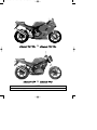
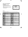
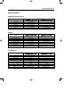
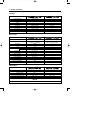
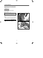
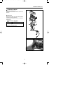
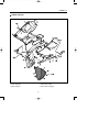
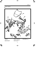
GT 125 R
GT 250 R
Euro 2, karburatormodel
ServiceManual
Se også
FI Service
Manual for
indsprøjtningsdelene og GT
250 Naked for
øvrige service
information
Holtvej 8-10, Høruphav
6470 Sydals
Telefon: +45 73 15 11 00
Fax: +45 73 15 11 01
E-mail: [email protected]
www.scanmi.dk
CVR: 27 73 31 07
GT250/125R(SM)내지 2006.7.261:58PM 페이지1001PagePro9100300DPI100LPI
GROUP INDEX
FOREWORD
This manual contains an introductory description on
HYOSUNG
&
and
procedures for its inspection/service and overhaul of its
main components.
It covers the differences from
and
please refer to the service manual of
(99000-94710) for others which are not covered in this manual.
This page numbers on the top are ones which are in the
service manual of
and ones on the
bottom are the page numbers in this manual.
Other information considered as generally known is not
included.
Read GENERAL INFORMATION section to familiarize
yourself with outline of the vehicle and MAINTENANCE
and other sections to use as a guide for proper
inspection and service.
This manual will help you know the vehicle better so that
you can assure your customers of your optimum and
quick service.
GENERAL INFORMATION
1
PERIODIC MAINTENANCE
2
ELECTRICAL SYSTEM
5
CHASSIS
6
SERVICING INFORMATION
7
� This manual has been prepared on the basis
of the latest specification at the time of
publication.
If modification has been made since then,
difference may exist between the content of
this manual and the actual vehicle.
� Illustrations in this manual are used to show
the basic principles of operation and work
procedures.
They may not represent the actual vehicle
exactly in detail.
WARNING
This manual is intended for those who have
enough knowledge and skills for servicing
HYOSUNG vehicles. Without such knowledge and
skills, you should not attempt servicing by relying
on this manual only.
Instead, please contact your nearby authorized
HYOSUNG motorcycle dealer.
HYOSUNG MOTORS & MACHINERY INC.
� COPYRIGHT HYOSUNG MOTORS & MACHINERY INC. 2006.
GT250/125R(SM)내지 2006.7.261:58PM 페이지2001PagePro9100300DPI100LPI
&
&
NOTE
Difference between photographs and actual motorcycles depends on the markets.
2
GT250/125R(SM)내지 2006.7.261:58PM 페이지3001PagePro9100300DPI100LPI
HOW TO USE THIS MANUAL
TO LOCATE WHAT YOU ARE
LOOKING FOR:
1. The text of this manual is divided into sections.
2. As the title of these sections are listed on the previous
page as GROUP INDEX, select the section where you are looking for.
3. Holding the manual as shown at the right will allow you to find
the first page of the section easily.
4. On the first page of each section, its contents are listed. Find
the item and page you need.
SYMBOL
Listed in the table below are the symbols indicating instructions and other information necessary for servicing and
meaning associated with them respectively.
SYMBOL
DEFINITION
SYMBOL
DEFINITION
Torque control required.
Data beside it indicates specified torque.
Apply THREAD LOCK“1324”
.
Apply oil. Use engine oil unless otherwise
specified.
Apply or use brake fluid.
Apply SUPER GREASE“A”
.
Measure in voltage range.
Apply SUPER GREASE“C”
.
Measure in resistance range.
Apply SILICONE GREASE.
Measure in current range.
Apply MOLY PASTE.
Use special tool.
Apply BOND“1215”
.
Use engine coolant.
Use fork oil.
3
GT250/125R(SM)내지 2006.7.261:58PM 페이지4001PagePro9100300DPI100LPI
4
GT250/125R(SM)내지 2006.7.261:58PM 페이지5001PagePro9100300DPI100LPI
GENERAL INFORMATION
1
CONTENTS
EXTERIOR ILLUSTRATION ……………………………………………… 6 (1-6)
SPECIFICATIONS ………………………………………………………… 7 (1-8)
5
GT250/125R(SM)내지 2006.7.261:58PM 페이지6001PagePro9100300DPI100LPI
1- 6 GENERAL INFORMATION
&
EXTERIOR ILLUSTRATION [
]
Turn signal lamp (Rear)
Tail / Brake lamp
License plate lamp
(WIDTH)
Rear
reflector
Turn signal lamp (Front)
Passenger footrests
(HEIGHT)
Head lamp
(WHEEL BASE)
(LENGTH)
6
GT250/125R(SM)내지 2006.7.261:58PM 페이지7001PagePro9100300DPI100LPI
GENERAL INFORMATION 1-8
SPECIFICATIONS
DIMENSIONS AND DRY MASS
ITEM
Overall length
Overall width
Overall height
Wheelbase
Ground clearance
Mass
2,060 mm
655 mm
1,125 mm
1,435 mm
130 mm
185 kg
(81.1 in)
(25.8 in)
(44.3 in)
(56.5 in)
(5.1 in)
(408 lbs)
←
←
←
←
←
180 kg (397 lbs)
ENGINE
ITEM
Type
Number of cylinder
Bore
Stroke
Piston displacement
Carburetor
Starter system
Lubrication system
Four-stroke, DOHC, Air cooled and oil cooled
V-2 cylinder
57.0 mm (2.24 in)
48.8 mm (1.92 in)
249 ㎤ (15.2 in3)
BDSR26 TYPE (DOUBLE)
Electric starter
Wet sump
←
←
44.0 mm (1.73 in)
41.0 mm (1.61 in)
124.7 ㎤ (7.6 in3)
←
←
←
Wet multi-plate type
5-speed constant mesh
1-down, 4-up
3.290
2.460
1.560
1.190
0.960
0.840
520HO 112 links
←
←
←
3.690
2.750
1.790
1.350
1.090
0.910
428HO 136 links
TRANSMISSION
ITEM
Clutch
Transmission
Gearshift pattern
Final reduction
Gear ratio, 1st
2nd
3rd
4th
5th
Drive chain
7
GT250/125R(SM)내지 2006.7.261:58PM 페이지8001PagePro9100300DPI100LPI
1-9 GENERAL INFORMATION
CHASSIS
ITEM
Front suspension
Rear suspension
Steering angle
Caster
Trail
Front brake
Rear brake
Front tire size
Rear tire size
Front fork stroke
Telescopic type
Swingarm type
27°(right & left)
25.5°
90 mm (3.54 in)
Double disc brake
Disc brake
110/70 - 17 54H
150/70 - 17 69H
120 mm (4.72 in)
←
←
←
←
←
Disc brake
←
←
←
←
“CDI”type
←
ELECTRICAL
ITEM
Ignition type
Ignition timing
Spark plug
Battery
Fuse
Head lamp
HI
LO
Position lamp
Turn signal lamp
Brake / Tail lamp
Illumination lamp
License plate lamp
High beam indicator lamp
Turn signal indicator lamp(right & left)
Neutral indicator lamp
Fuel indicator lamp
13°B.T.D.C. at 2,000 rpm and
30°B.T.D.C. at 6,000 rpm
13°B.T.D.C. at 2,000 rpm and
30°B.T.D.C. at 5,000 rpm
CR8E
12V 12Ah (MF)
15 A
12V - H1 : 55W ×1
12V - H3 : 55W ×1
12V - 5W × 1
12V - 10W × 4
12V - 21/5W × 1
12V - 1.7W × 2
12V - 5W × 1
VFD
VFD
VFD
VFD (Level type)
←
←
←
←
←
←
←
←
←
←
←
←
←
←
17.0 ℓ
1,450 ㎖
1,500 ㎖
1,800 ㎖
400± 2.5 cc
←
←
←
1,650 ㎖
400± 2.5 cc
CAPACITIES
ITEM
Fuel tank
Engine oil, oil change
with filter change
overhaul
Front fork oil capacity(One side)
NOTE
The specifications are subject to change without notice.
8
GT250/125R(SM)내지 2006.7.261:58PM 페이지9001PagePro9100300DPI100LPI
PERIODIC MAINTENANCE
2
CONTENTS
2
MAINTENANCE PROCEDURES
CARBURETOR ………………………………………………………… 10 (2-7)
CLUTCH ………………………………………………………………… 11 (2-8-1)
9
GT250/125R(SM)내지 2006.7.261:58PM 페이지10001PagePro9100300DPI100LPI
2-7 PERIODIC MAINTENANCE
MAINTENANCE PROCEDURES
CARBURETOR
Inspect Interval
Inspect Initial 1,000 km and Every 4,000 km.
◉ IDLE SPEED
NOTE
Make this inspection when the engine is hot.
● Connect an engine tachometer to the high tension
cord.
Start up the engine and set its speed at anywhere
1,400 and 1,500 rpm by turning throttle stop screw �.
Engine idle speed
1,400�1,500 rpm
Engine tachometer : 09900-26006
�
10
GT250/125R(SM)내지 2006.7.261:58PM 페이지11001PagePro9100300DPI100LPI
2-8-1 PERIODIC MAINTENANCE
CLUTCH
◉ FOOTREST POSITION ADJUSTMENT
�
&
have 3 type of
the footrest position, right and left.
To change the position, remove the 8mm wrench bolts
①, ② and install the bolts to the desired position by
using the hexagon wrench 6mm.
&
from the factory on position �.
�
are delivered
[ POSITION � ]
WARNING
�
When adjusting the footrest position, the 8mm
wrench bolts be torqued to the proper
specification.
If they are not, the footrest can come off
unexpectedly.
�
Footrest mounting bolt
∙m (2.2 ~ 3.5 kgf∙
∙m)
: 22 ~ 35 N∙
[ POSITION � ]
�
�
[ POSITION � ]
11
GT250/125R(SM)내지 2006.7.261:58PM 페이지12001PagePro9100300DPI100LPI
PERIODIC MAINTENANCE 2-8-2
◉ GEARSHIFT LINK ROD
(FOR
OPTIONAL PARTS)
&
’S
When the footrests in position �, exchange the gearshift
link rod for appropriate riding position.
③
● Position � or �
: Install the gearshift link rod ③
● Position �
: Install the gearshift link rod ④
④ [Optional parts]
NOTE
The gearshift link rod ④ is optional parts.
12
GT250/125R(SM)내지 2006.7.261:58PM 페이지13001PagePro9100300DPI100LPI
ELECTRICAL SYSTEM
CONTENTS
LAMP………………………………………………………………………… 14 (5-16-1)
5
13
GT250/125R(SM)내지 2006.7.261:58PM 페이지14001PagePro9100300DPI100LPI
ELECTRICAL SYSTEM 5-16-1
LAMP
◉ HEAD LAMP
� REPLACEMENT OF HEAD LAMP BULB
● Remove the under cowling.
(Refer to page 6-1-2 ~ 3)
● Remove the body cowling.
(Refer to page 6-1-4 ~ 5)
● Remove the head lamp coupler ①, ②.
①
②
● Remove the dust cover ③.
③
14
GT250/125R(SM)내지 2006.7.261:58PM 페이지15001PagePro9100300DPI100LPI
5-16-2 ELECTRICAL SYSTEM
● Remove the socket spring ①.
①
● Remove the bulb ② and replace the new bulb.
②
● Remove the head lamp “HI” bulb with the same
manner of the head lamp “LOW” bulb removal.
● Reinstall the head lamp bulb in the reverse order of
head lamp bulb removal.
15
GT250/125R(SM)내지 2006.7.261:58PM 페이지16001PagePro9100300DPI100LPI
ELECTRICAL SYSTEM 5-17-1
◉ COMBINATION METER
Remove the combination meter.
Disassemble the combination meter as shown in the
illustration.
� INSPECTION
Using the pocket tester, check the continuity between
lead wires in the following illustration.
If the continuity measured incorrect, replace the
respective part.
Pocket tester : 09900-25002
CAUTION
When making this test, it is not necessary to
remove the combination meter.
16
GT250/125R(SM)내지 2006.7.261:58PM 페이지17001PagePro9100300DPI100LPI
5-17-2 ELECTRICAL SYSTEM
17
GT250/125R(SM)내지 2006.7.261:58PM 페이지18001PagePro9100300DPI100LPI
18
GT250/125R(SM)내지 2006.7.261:58PM 페이지19001PagePro9100300DPI100LPI
CHASSIS
CONTENTS
EXTERIOR PARTS ………………………………………………………… 20 (6-1-1)
HANDLEBARS …………………………………………………………… 25 (6-12-1)
STEERING ………………………………………………………………… 29 (6-27)
6
19
GT250/125R(SM)내지 2006.7.261:58PM 페이지20001PagePro9100300DPI100LPI
6-1-1 CHASSIS
EXTERIOR PARTS
◉ REAR CARRIER
� REMOVAL
● Open the rear seat with the ignition key.
● Remove the rear carrier mounting bolts ① and
separate the rear carrier ②.
②
①
①
� INSTALLATION
Reassemble the rear carrier in the reverse order of
removal.
● To reinstall the rear seat, slide the seat hook into the
seat hook retainer and push down firmly until the seat
snaps into the locked position.
20
GT250/125R(SM)내지 2006.7.261:58PM 페이지21001PagePro9100300DPI100LPI
CHASSIS 6-1-2
◉ UNDER COWLING
�
�
�
�
① Under cowling RH
② Under cowling LH
③ Under center cowling
④ Under center cowling grill
21
GT250/125R(SM)내지 2006.7.261:58PM 페이지22001PagePro9100300DPI100LPI
6-1-3 CHASSIS
� REMOVAL
● Remove the under cowling screws at the rightside.
● Remove the under cowling screws at the leftside.
22
GT250/125R(SM)내지 2006.7.261:58PM 페이지23001PagePro9100300DPI100LPI
CHASSIS 6-1-4
◉ BODY COWLING
�
�
�
�
�
�
�
�
�
�
① Windscreen
② Meter panel
③ Body side cowling RH
④ Body side cowling LH
⑤ Body side cowling inner RH
⑥ Body side cowling lower RH
⑦ Body side cowling lower LH
⑧ Air duct cowling RH
23
⑨ Air duct cowling LH
⑩ Body center lower cowling
GT250/125R(SM)내지 2006.7.261:58PM 페이지24001PagePro9100300DPI100LPI
6-1-5 CHASSIS
� REMOVAL
● Remove the body cowling screw at the rightside.
● Remove the body cowling screw at the leftside.
● Remove the two cowling brace bolts.
● Remove the speedometer lead wire and head lamp
lead wire.
� REMOUNTING
● Tighten the two cowling brace bolts.
Cowling brace bolt
∙m (2.2 ~ 3.5 kg∙
∙m)
: 22 ~ 35 N∙
24
GT250/125R(SM)내지 2006.7.261:58PM 페이지25001PagePro9100300DPI100LPI
CHASSIS 6-12-1
HANDLEBARS
�
�
�
�
�
① Handlebar composition RH
② Handlebar composition LH
�
③ Rear view mirror assembly RH ⑤ Handlebar switch assembly RH
④ Rear view mirror assembly LH ⑥ Handlebar switch assembly LH
■ HANDLEBAR RIGHT SIDE PARTS REMOVAL
● Remove the right handlebar switches.
● Disconnect the brake lamp switch lead wires and
remove the master cylinder.
☞ Refer to the service manual
(99000-94710) page 6-10
● Remove the handlebar balancer ⑦ and grip ⑧.
⑧
25
⑦
GT250/125R(SM)내지 2006.7.261:58PM 페이지26001PagePro9100300DPI100LPI
6-12-2 CHASSIS
■ HANDLEBAR LEFT SIDE PARTS REMOVAL
● Remove the left handlebar switches.
● Remove the handlebar balancer ① and grip ②.
● Remove the clutch lever holder.
①
②
● Loosen the handlebar clamp bolts, right and left.
● Loosen the front fork upper clamp bolt, right and left.
● Remove the steering stem upper bracket by removing
the steering stem head nut.
NOTE
Place the rags under the steering stem upper
bracket to prevent scratching the body cowling.
26
GT250/125R(SM)내지 2006.7.261:58PM 페이지27001PagePro9100300DPI100LPI
CHASSIS 6-13-1
● Remove the handlebar holder bolt, right and left.
● Draw out the handlebars to upward.
■ REMOUNTING
Remount the handlebar in the reverse order of removal.
Pay attention to the following point :
● Install the handlebars temporary.
● Install the steering stem upper bracket.
● Tighten the steering stem head nut.
Steering stem head nut
∙m (8.0 ~ 10.0 kg∙
∙m)
: 80 ~ 100 N∙
● Tighten the front fork upper clamp bolt, right and left.
Front fork upper clamp bolts
: 22 ~ 35 N∙m (2.2 ~ 3.5 kg∙m)
● Tighten the handlebar clamp bolts, right and left.
Handlebar clamp bolt
∙m (2.2 ~3.5 kg∙
∙m)
: 22 ~ 35 N∙
27
GT250/125R(SM)내지 2006.7.261:58PM 페이지28001PagePro9100300DPI100LPI
6-13-2 CHASSIS
● When remounting the clutch lever holder, align the
holder’s mating surface � with punch mark � on the
handlebar.
Upper
�
Clutch lever holder
Handlebar
�
�
● When remounting the front brake master cylinder
onto the handlebar, align the master cylinder holder’s
mating surface � with punch mark � on the
handlebar and tighten the upper clamp bolt first as
shown.
Upper
�
Handlebar
WARNING
�
�
Master
cylinder
holder
Bleed air from the brake fluid circuit after
assembling master cylinder.
☞ Refer to the service manual『
(99000-94710) page 2 - 16
● Apply SUPER GREASE“A”to the throttle cables.
Throttle grip
SUPER GREASE“A”
● Install the throttle cable to the throttle grip ①.
① : Throttle cable
Throttle
cable
28
Rotation
direction
GT250/125R(SM)내지 2006.7.261:58PM 페이지29001PagePro9100300DPI100LPI
CHASSIS 6-27
STEERING
◉ REMOVAL AND DISASSEMBLY
● Remove the under cowling and body cowling.
(Refer to page 6-1-2 ~ 5)
● Take off the front wheel.
☞ Refer to the service manual『
(99000-94710) page 6-2
● Remove the four bolts and front fender.
● Take off the front fork.
☞ Refer to the service manual『
(99000-94710) page 6-14
29
GT250/125R(SM)내지 2006.7.261:58PM 페이지30001PagePro9100300DPI100LPI
6-28 CHASSIS
● Remove the handlebar clamp bolts.
● Remove the steering stem head nut ① and take off
the steering stem upper bracket ②.
①
②
● Remove the steering stem nut ③ and draw out the
steering stem.
③
Clamp wrench : 09940-10122
● Take off the steering stem lower bracket ④.
⑤
CAUTION
Hold the steering stem lower bracket by hand to
prevent from falling.
④
● Remove the upper and lower bearings ⑤.
● Remove the outer race fitted on the steering stem.
This can be done with a chisel.
● Draw out the two inner races fitted to the top and
bottom ends of the head pipe.
30
GT250/125R(SM)내지 2006.7.261:58PM 페이지31001PagePro9100300DPI100LPI
CHASSIS 6-29-1
◉ INSPECTION
Inspect and check the removed parts for the following
abnormalities.
∙Handlebar distortion.
∙Handlebar clamp wear.
∙Abnormality operation of bearing.
∙Worn or damaged races.
∙Distortion of steering stem.
◉ REASSEMBLY
Reassemble and remount the steering stem in the
reverse order of disassembly and removal, and also
carry out the following steps :
②
● Apply SUPER GREASE“A”to the upper bearing
and lower bearing ①.
①
”
SUPER GREASE“A”
● Tighten the steering stem nut ② with the special tool.
Clamp wrench : 09940-10122
Steering stem nut
∙m (8.0 ~ 10.0 kg∙
∙m)
: 80 ~ 100 N∙
● Turn the steering stem right and left, lock-to-lock, five
or six times.
● Tighten the steering stem head nut ③ to the specified
torque.
Steering stem head nut
∙m (8.0 ~ 10.0 kg∙
∙m)
: 80 ~ 100 N∙
CAUTION
③
After performing the adjustment and installing
the steering stem upper bracket, rock the front
wheel assembly forward and backward to ensure
that there is no play and that the procedure was
accomplished correctly. If play is noticeable, readjust the steering stem nut.
31
GT250/125R(SM)내지 2006.7.261:58PM 페이지32001PagePro9100300DPI100LPI
6-29-2 CHASSIS
● Tighten the handlebar clamp bolts, right and left.
Handlebar clamp bolts
∙m (2.2 ~ 3.5 kg∙
∙m)
: 22 ~ 35 N∙
32
GT250/125R(SM)내지 2006.7.261:58PM 페이지33001PagePro9100300DPI100LPI
SERVICING INFORMATION
CONTENTS
SERVICE DATA …………………………………………………………… 34 (7-20)
WIRING DIAGRAM ………………………………………………………… 35 (7-31)
7
33
GT250/125R(SM)내지 2006.7.261:58PM 페이지34001PagePro9100300DPI100LPI
7-20 SERVICING INFORMATION
SERVICE DATA
WATTAGE
Unit : W
SPECIFICATION
ITEM
Head lamp
HI
H1 : 55W
LO
H3 : 55W
Position lamp
5W
License plate lamp
5W
Brake/Tail lamp
21/5W
Turn signal lamp
Front : 10W×2 / Rear : 10W×2
Illumination lamp
1.7W×2
Neutral indicator lamp
VFD
Turn signal indicator lamp (Right & left)
VFD
High beam indicator lamp
VFD
Fuel indicator lamp
VFD
CAUTION
Do not use except the specified bulb (Wattage).
NOTE
VFD : Vacuum Fluorescent Display
34
Level type
WIRE COLOR
B : Black
Br : Brown
G : Green
Gr : Gray
L : Blue
Lg
O
R
Sb
W
:
:
:
:
:
Light green
Orange
Red
Light blue
White
Y
BG
BW
BR
LW
: Yellow
: Black with Green tracer
: Black with White tracer
: Black with Red tracer
: Blue with White tracer
RB
RW
WB
WR
YB
: Red with Black tracer
: Red with White tracer
: White with Black tracer
: White with Red tracer
: Yellow with Black tracer
GT250/125R(SM)내지 2006.7.261:58PM 페이지35001PagePro9100300DPI100LPI
SERVICING INFORMATION 7-31
WIRING DIAGRAM
35
GT250/125R(SM)내지 2006.7.261:58PM 페이지36001PagePro9100300DPI100LPI
Prepared by
HYOSUNG MOTORS & MACHINERY INC.
1st Ed. JUL. 2006.
Manual No. 99000HR8310
Printed in Korea