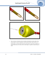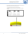
1
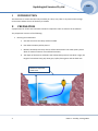
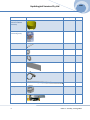
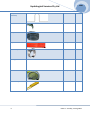
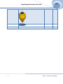
2009 Hydrological Services Pty Ltd QUALITY SYSTEM ISO 9001 CERTIFIED HYDROLOGICAL SERVICES PTY LTD PO BOX 332, LIVERPOOL B.C NSW 1871, AUSTRALIA Phone: (Int.) 612 9601 2022 Fax: (Int.) 612 9602 6971 Phone: ( Nat.) (02) 9601 2022 Fax: (Nat.) (02) 9602 6971 1 ISSUE 1: Tuesday, 25 Aug 2009 Hydrological Services Pty Ltd 2009 Contents
I INTRODUCTION ............................................................................................................................... 3 II PREPARATION ................................................................................................................................. 3 III INSTALLATION ................................................................................................................................. 8 2 ISSUE 1: Tuesday, 25 Aug 2009 2009 Hydrological Services Pty Ltd I
INTRODUCTION
This document is used to install a buoy assembly in a dam, river, lake or any other water storage environment where the use of the buoy is suitable II
PREPARATION
A preparation for all the tools and items needed is required in order to achieve the installation. The preparation consists of the following: 1. Planning and calculations a. Visit the site where the Buoy will be installed b. Plan where the Buoy will be placed c. Measure how deep the buoy anchor will be submersed in the water (Note: please allow for maximum water rise and flood situation) d. The depth of the Anchor will define the submersible pressure transducer range, the length of transducer lead, poly drain pipe, layflat, fishing wire and the feed wire. Maximum expected water level 3 ISSUE 1: Tuesday, 25 Aug 2009 2009 Hydrological Services Pty Ltd 2. Purchase the required items from a hardware store; items required are as follows: a. Tapered shape Bucket to mould the concrete anchor approximately between 300mm and 350mm in diameter b. Mixed concrete 2 X bags, 20 Kgs each (cement, sand and gravel) c. 2 X M24 (or 1”) bolts by 200mm long, 2 X washers and 2X locknuts. All materials should be in stainless steel d. 2 X flat bars between 100 and 150 mm in length e. Drill with a 25 MM diameter drill bit, pliers, screw driver, measuring tape, level, etc….. f.
1.5 metre stainless steel chain g. 2 X D‐shackle internal dimensions greater or equal to 25mm h. A welder that can spot weld the 2 nuts to the 2 washers i.
Stanley knife j.
6.5mm rod k. Poly Drain pipe 50mm outside diameter (Length depends on the maximum water level). If Poly Dain pipe shorter than required length a poly drain union is required to join two pipes together l.
Layflat (Length depends on the maximum water level) m. 4 X hose clamps to suit 2” nominal bore pipe n. Fishing wire, less or equal to 2 mm in diameter (Length should be twice the maximum water level) o. Feed wire to feed the fishing wire through the poly drain pipe p. Anchor adaptor (this item is supplied by Hydrological Services) q. Buoy assembly (this item is supplied by hydrological Services) r.
Submersible pressure transducer (this item is supplied by hydrological Services) 4 ISSUE 1: Tuesday, 25 Aug 2009 2009 Hydrological Services Pty Ltd Item Photo Quantity Bucket (tapered minimum 300mm diameter) Tick
1 Concrete (mixed sand, cement & gravel) 2 Bolt M24 1 2 Nut M24 Washer M24 2 1 Flat bar (2‐3mm thick) D‐shackle 2 Chain (1.5 metre) 1.5 metre Weld (Washer & Nut) ‐ Stanley knife 1 5 ISSUE 1: Tuesday, 25 Aug 2009 2009 Hydrological Services Pty Ltd Rod (6 to 6.5mm diameter) Drill & drill bits 1 Poly Drain As required Layflat As required Hose Clamp 4 Fishing wire As required Feed wire As required Anchor adaptor 1 6 ISSUE 1: Tuesday, 25 Aug 2009 2009 Hydrological Services Pty Ltd Buoy 1 Pressure Transducer Tools 1 Drill, Screw driver, pliers, measuring tape, level etc….
‐ 7 ISSUE 1: Tuesday, 25 Aug 2009 2009 Hydrological Services Pty Ltd III INSTALLATION
1. Make the first anchor block a. Drill a 25 mm hole in the centre of the 2 flat bars as shown below Drill 25mm hole
b. Attach the flat bar to the M24 bolt as shown below 8 ISSUE 1: Tuesday, 25 Aug 2009 2009 Hydrological Services Pty Ltd c. Mark how deep the bolt will go inside the concrete – and drill a 3mm hole through the bolt as shown, to accept a split pin. This will stop the nut unscrewing as the buoy rotates with the tide/wind. 3mm hole Bolt should be 140mm above concrete allowing the anchor adapter to swivel easily. 140MM 60MM d. Mix your first bag of concrete as instructed 9 ISSUE 1: Tuesday, 25 Aug 2009 2009 Hydrological Services Pty Ltd e. Pour the mixed concrete bag inside the bucket ; push the bolt and the flat bar inside the concrete so the mark on the bolt is level with the top of the concrete and smooth the surface around f.
Ensure the bolt is vertically level and wait till dry 140MM 10 ISSUE 1: Tuesday, 25 Aug 2009 2009 Hydrological Services Pty Ltd 2. Make the second anchor block a. The second anchor block is done using a 6.5mm rod, which is bent as shown below 120mm 250mm b. Use the second concrete bag and the tapered bucket to mould the second anchor as shown below 3. Weld the 2 washers to the hex nuts Washer outside diameter 46mm minimum & 48mm maximum 11 ISSUE 1: Tuesday, 25 Aug 2009 2009 Hydrological Services Pty Ltd 4. Assembling the buoy to the poly drain and layflat a. Say the maximum length needed is the value x b. Using the Stanley knife and the measuring tape cut the layflat to the value of x X mm c. Cut the poly drain pipe to the value of [(x+1000) mm] (i.e. 1 metre longer than the layflat) X+1000 mm d. Feed the poly drain pipe through the layflat as shown below 125 mm 875 mm 12 ISSUE 1: Tuesday, 25 Aug 2009 2009 Hydrological Services Pty Ltd e. Assemble the poly drain pipe and layflat to anchor adaptor and the buoy using the 4 hose clamps Roll Pin Polydrain Pipe Step1: Slide the Polydrain pipe till it makes contact with the pin 13 ISSUE 1: Tuesday, 25 Aug 2009 2009 Hydrological Services Pty Ltd Step2: Tighten the Layflat to the recess on the Anchor adaptor to avoid slippage using the 2 Hose clamps as shown. Recess
Step3: Slide the Poly drain pipe inside the steel pipe till the layflat covers the recess on the steel pipe 14 ISSUE 1: Tuesday, 25 Aug 2009 2009 Hydrological Services Pty Ltd Step4: Tighten the Layflat to the recess on the steel pipe to avoid slippage using the 2 Hose clamps as shown. Step5: using the knife, cut the excess of the poly drain pipe flash with the steel plate as shown 15 ISSUE 1: Tuesday, 25 Aug 2009 2009 Hydrological Services Pty Ltd f.
Loop and twist the end of the wire through as shown below g. Feed the wire all the way through the Poly Drain pipe, till you reach the other end 16 ISSUE 1: Tuesday, 25 Aug 2009 2009 Hydrological Services Pty Ltd h. Cut a fishing wire to the right length; this fishing wire is looped around the roll pin of the anchor block and is used to push the transducer inside the poly drain pipe. The fishing wire stays permanently wired in the buoy assembly in case the transducer need to be replaced, checked, cleaned etc… The length of the fishing wire should me minimum 2.5 times the length of the poly drain pipe. One end of the fishing wire goes around the anchor adaptor roll pin and then to the looped feed wire as shown The other end of the fishing wire goes straight to the feed wire as shown Anchor adaptor roll pin i.
Make a knot of the fishing wire around the looped feed wire and pull the feed wire back to the buoy end. 17 ISSUE 1: Tuesday, 25 Aug 2009 2009 Hydrological Services Pty Ltd j.
The next step is to feed the pressure transducer through the poly drain pipe, using the fishing wire. Once the fishing line reaches the buoy side; undo the knot or cut the fishing line to separate both ends from the feed wire. The pressure transducer is supplied separately to the Buoy and the cable length is supplied as requested by the client. 18 ISSUE 1: Tuesday, 25 Aug 2009 2009 Hydrological Services Pty Ltd k. Once both ends of the fishing wire are freed, take one end and feed it through the hole on the pressure transducer nose cone. Tie a double knot as this connection will remain permanent as long as the pressure transducer is in use. Nose cone hole Tie a double knot Feed Pull & wind this end neatly on a rolled object that can be placed permanently inside the buoy 19 ISSUE 1: Tuesday, 25 Aug 2009 2009 Hydrological Services Pty Ltd l.
Keep pulling the fishing wire till the nose cone of the pressure transducer make contact with the anchor adaptor roll pin. m. The excess fishing wire should remain inside the buoy housing at all times; It is only unwind when the pressure transducer is pulled out for checking, cleaning or replacement. 20 ISSUE 1: Tuesday, 25 Aug 2009 2009 Hydrological Services Pty Ltd n. The next step is to wire the pressure transducer to the water level transmitter. The schematic below illustrates how the wiring is performed. ‐ The WLT420 Transmitter will accept a 4‐20mA transducer only. ‐ The WDC100 Transmitter will accept either a 4‐20mA transducer or an SDI‐12 transducer. WL2100 WLT420 WDC100 Red or Brown wire 4‐20mA + Power +12V Black or Blue wire 4‐20mA ‐ Ground 0V White is SDI‐12 Data Not connected SDI‐12 Data Green is shield Not connected Not connected 21 ISSUE 1: Tuesday, 25 Aug 2009 2009 Hydrological Services Pty Ltd WLT420 Connection 2) Connect red or brown cable (4‐20mA (+)) from pressure transducer to TX+ on the WLT420 circuit board 4) Battery power is connected to (+12) and (0V) 3) Connect black or blue cable (4‐20mA (‐)) from pressure transducer to TX‐ on the WLT420 circuit board 1) Feed pressure transducer cable the gland as shown
Note: To set up the WLT420 please refer to the WLT420 instruction manual. 22 ISSUE 1: Tuesday, 25 Aug 2009 2009 Hydrological Services Pty Ltd WDC100 Connection 4) 5) Connect black or blue cable Power 0V from pressure transducer to 0V on the WDC100 circuit board Battery power is connected to (+12) and (0V) 3) Connect white cable SDI‐12 data from pressure transducer to Data on the WDC100 circuit board 2) Connect red or brown cable Power +12V from pressure transducer to Sw+ on the WDC100 circuit board 1) Feed pressure transducer cable the gland as shown
Note: To set up the WDC100 please refer to the WDC100 instruction manual. 23 ISSUE 1: Tuesday, 25 Aug 2009 2009 Hydrological Services Pty Ltd o. Replace the lid for the WLT420 / WDC100 and the Buoy after setting up all the parameters as required. p. It is time now to assemble the anchor blocks together. Place the two concrete anchors approximately 1.5 metres apart. 3. Secure the D shackle using the welded nut and washer. Screw the nut really tight so the D shackle does not rotate and making firm contact with the washer/nut and the anchor surface 1. Assemble the D shackles to each end of the chain 2. Assemble the D shackle/ chain to the hook of the first anchor block 24 ISSUE 1: Tuesday, 25 Aug 2009 2009 Hydrological Services Pty Ltd q. The final step prior to submersing the pressure transducer in the water is to assemble the two anchors to the anchor block adaptor. Use the second nut and washer after they have been welded together. Screw the nut keeping the anchor adaptor free to swivel Insert split pin to stop nut unscrewing r.
Deploy the buoy assembly 25 ISSUE 1: Tuesday, 25 Aug 2009