1
100
System 4xiEQ
Series
VideoQuadrupler
Equalizer
System 4LQxi • Switcher/Line
System 4LDxi • Switcher/Line Doubler
68-162-01
Printed in USA
Precautions
Safety Instructions • English
This symbol is intended to alert the user of important operating and maintenance
(servicing) instructions in the literature provided with the equipment.
This symbol is intended to alert the user of the presence of uninsulated dangerous
voltage within the product's enclosure that may present a risk of electric shock.
Warning
Power sources • This equipment should be operated only from the power source indicated on the
product. This equipment is intended to be used with a main power system with a grounded
(neutral) conductor. The third (grounding) pin is a safety feature, do not attempt to bypass or
disable it.
Caution
Power disconnection • To remove power from the equipment safely, remove all power cords from
the rear of the equipment, or the desktop power module (if detachable), or from the power
source receptacle (wall plug).
Read Instructions • Read and understand all safety and operating instructions before using the
equipment.
Power cord protection • Power cords should be routed so that they are not likely to be stepped on or
pinched by items placed upon or against them.
Retain Instructions • The safety instructions should be kept for future reference.
Servicing • Refer all servicing to qualified service personnel. There are no user-serviceable parts
inside. To prevent the risk of shock, do not attempt to service this equipment yourself because
opening or removing covers may expose you to dangerous voltage or other hazards.
Follow Warnings • Follow all warnings and instructions marked on the equipment or in the user
information.
Avoid Attachments • Do not use tools or attachments that are not recommended by the equipment
manufacturer because they may be hazardous.
Slots and openings • If the equipment has slots or holes in the enclosure, these are provided to
prevent overheating of sensitive components inside. These openings must never be blocked by
other objects.
Lithium battery • There is a danger of explosion if battery is incorrectly replaced. Replace it only with
the same or equivalent type recommended by the manufacturer. Dispose of used batteries
according to the manufacturer's instructions.
Consignes de Sécurité • Français
Avertissement
Ce symbole sert à avertir l’utilisateur que la documentation fournie avec le matériel
contient des instructions importantes concernant l’exploitation et la maintenance
(réparation).
Alimentations• Ne faire fonctionner ce matériel qu’avec la source d’alimentation indiquée sur
l’appareil. Ce matériel doit être utilisé avec une alimentation principale comportant un fil de
terre (neutre). Le troisième contact (de mise à la terre) constitue un dispositif de sécurité :
n’essayez pas de la contourner ni de la désactiver.
Ce symbole sert à avertir l’utilisateur de la présence dans le boîtier de l’appareil de
tensions dangereuses non isolées posant des risques d’électrocution.
Déconnexion de l’alimentation• Pour mettre le matériel hors tension sans danger, déconnectez tous
les cordons d’alimentation de l’arrière de l’appareil ou du module d’alimentation de bureau (s’il
est amovible) ou encore de la prise secteur.
Attention
Lire les instructions• Prendre connaissance de toutes les consignes de sécurité et d’exploitation avant
d’utiliser le matériel.
Conserver les instructions• Ranger les consignes de sécurité afin de pouvoir les consulter à l’avenir.
Respecter les avertissements • Observer tous les avertissements et consignes marqués sur le matériel ou
présentés dans la documentation utilisateur.
Eviter les pièces de fixation • Ne pas utiliser de pièces de fixation ni d’outils non recommandés par le
fabricant du matériel car cela risquerait de poser certains dangers.
Protection du cordon d’alimentation • Acheminer les cordons d’alimentation de manière à ce que
personne ne risque de marcher dessus et à ce qu’ils ne soient pas écrasés ou pincés par des objets.
Réparation-maintenance • Faire exécuter toutes les interventions de réparation-maintenance par un
technicien qualifié. Aucun des éléments internes ne peut être réparé par l’utilisateur. Afin
d’éviter tout danger d’électrocution, l’utilisateur ne doit pas essayer de procéder lui-même à ces
opérations car l’ouverture ou le retrait des couvercles risquent de l’exposer à de hautes tensions
et autres dangers.
Fentes et orifices • Si le boîtier de l’appareil comporte des fentes ou des orifices, ceux-ci servent à
empêcher les composants internes sensibles de surchauffer. Ces ouvertures ne doivent jamais
être bloquées par des objets.
Lithium Batterie • Il a danger d'explosion s'll y a remplacment incorrect de la batterie. Remplacer
uniquement avec une batterie du meme type ou d'un ype equivalent recommande par le
constructeur. Mettre au reut les batteries usagees conformement aux instructions du fabricant.
Sicherheitsanleitungen • Deutsch
Vorsicht
Dieses Symbol soll den Benutzer auf wichtige Anleitungen zur Bedienung und
Wartung (Instandhaltung) in der Dokumentation hinweisen, die im Lieferumfang
dieses Gerätes enthalten ist.
Stromquellen • Dieses Gerät sollte nur über die auf dem Produkt angegebene Stromquelle betrieben
werden. Dieses Gerät wurde für eine Verwendung mit einer Hauptstromleitung mit einem
geerdeten (neutralen) Leiter konzipiert. Der dritte Stift oder Kontakt ist für einen Erdschluß, und
stellt eine Sicherheitsfunktion dar und sollte nicht umgangen oder außer Betrieb gesetzt werden.
Dieses Symbol soll den Benutzer darauf aufmerksam machen, daß im Inneren des
Gehäuses dieses Produktes gefährliche Spannungen, die nicht isoliert sind und
die einen elektrischen Schock verursachen können, herrschen.
Stromunterbrechung • Um das Gerät auf sichere Weise vom Netz zu trennen, sollten Sie alle
Netzkabel aus der Rückseite des Gerätes oder aus dem Desktop-Strommodul (falls dies möglich
ist) oder aus der Wandsteckdose ziehen.
Achtung
Lesen der Anleitungen • Bevor Sie das Gerät zum ersten Mal verwenden, sollten Sie alle Sicherheits-und
Bedienungsanleitungen genau durchlesen und verstehen.
Aufbewahren der Anleitungen • Die Sicherheitsanleitungen sollten aufbewahrt werden, damit Sie
später darauf zurückgreifen können.
Befolgen der Warnhinweise • Befolgen Sie alle Warnhinweise und Anleitungen auf dem Gerät oder in
der Benutzerdokumentation.
Keine Zusatzgeräte • Verwenden Sie keine Werkzeuge oder Zusatzgeräte, die nicht ausdrücklich vom
Hersteller empfohlen wurden, da diese eine Gefahrenquelle darstellen können.
Schutz des Netzkabels • Netzkabel sollten stets so verlegt werden, daß sie nicht im Weg liegen und
niemand darauf treten kann oder Objekte darauf- oder unmittelbar dagegengestellt werden
können.
Wartung • Alle Wartungsmaßnahmen sollten nur von qualifiziertem Servicepersonal durchgeführt
werden. Im Inneren des Gerätes sind keine Teile enthalten, die vom Benutzer gewartet werden können.
Zur Vermeidung eines elektrischen Schocks versuchen Sie in keinem Fall, dieses Gerät selbst zu
warten, da beim Öffnen oder Entfernen der Abdeckungen die Gefahr eines elektrischen Schlags
oder andere Gefahren bestehen.
Schlitze und Öffnungen • Wenn das Gerät Schlitze oder Löcher im Gehäuse aufweist, dienen diese
zur Vermeidung einer Überhitzung der empfindlichen Teile im Inneren. Diese Öffnungen dürfen
niemals von anderen Objekten blockiert werden.
Litium-Batterie • Explosionsgefahr, falls die Batterie nicht richtig ersetzt wird. Ersetzen Sie nur durch
die gleiche oder einen vergleichbaren Batterietyp, der auch vom Hersteller empfohlen wird.
Entsorgung der verbrauchten Batterien bitte gemäß den Herstelleranweisungen.
Instrucciones de seguridad • Español
Advertencia
Este símbolo se utiliza para advertir al usuario sobre instrucciones importantes de
operación y mantenimiento (o cambio de partes) que se desean destacar en el
contenido de la documentación suministrada con los equipos.
Alimentación eléctrica • Este equipo debe conectarse únicamente a la fuente/tipo de alimentación
eléctrica indicada en el mismo. La alimentación eléctrica de este equipo debe provenir de un
sistema de distribución general con conductor neutro a tierra. La tercera pata (puesta a tierra) es
una medida de seguridad, no puentearia ni eliminaria.
Este símbolo se utiliza para advertir al usuario sobre la presencia de elementos con
voltaje peligroso sin protección aislante, que puedan encontrarse dentro de la caja
o alojamiento del producto, y que puedan representar riesgo de electrocución.
Desconexión de alimentación eléctrica • Para desconectar con seguridad la acometida de
alimentación eléctrica al equipo, desenchufar todos los cables de alimentación en el panel trasero
del equipo, o desenchufar el módulo de alimentación (si fuera independiente), o desenchufar el
cable del receptáculo de la pared.
Precaucion
Leer las instrucciones • Leer y analizar todas las instrucciones de operación y seguridad, antes de usar
el equipo.
Conservar las instrucciones • Conservar las instrucciones de seguridad para futura consulta.
Obedecer las advertencias • Todas las advertencias e instrucciones marcadas en el equipo o en la
documentación del usuario, deben ser obedecidas.
Evitar el uso de accesorios • No usar herramientas o accesorios que no sean especificamente
recomendados por el fabricante, ya que podrian implicar riesgos.
Protección del cables de alimentación • Los cables de alimentación eléctrica se deben instalar en
lugares donde no sean pisados ni apretados por objetos que se puedan apoyar sobre ellos.
Reparaciones/mantenimiento • Solicitar siempre los servicios técnicos de personal calificado. En el
interior no hay partes a las que el usuario deba acceder. Para evitar riesgo de electrocución, no
intentar personalmente la reparación/mantenimiento de este equipo, ya que al abrir o extraer las
tapas puede quedar expuesto a voltajes peligrosos u otros riesgos.
Ranuras y aberturas • Si el equipo posee ranuras o orificios en su caja/alojamiento, es para evitar el
sobrecalientamiento de componentes internos sensibles. Estas aberturas nunca se deben obstruir
con otros objetos.
Batería de litio • Existe riesgo de explosión si esta batería se coloca en la posición incorrecta. Cambiar
esta batería únicamente con el mismo tipo (o su equivalente) recomendado por el fabricante.
Desachar las baterías usadas siguiendo las instrucciones del fabricante.
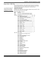
Contents
System 4xi Switcher Series
Getting Started..........
tt
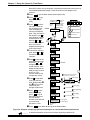
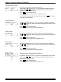
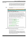
Step 1 uu
If the System 4xi is already configured for your model of projector, go to Step 4. If it is not set
up correctly, it will be necessary to change switch settings on the System 4xi ’s Main
Controller Board. Continue with Step 2 below to verify the correct configuration.
tt
Step 2 uu
Apply power to the System 4xi. Use the front panel to display the Information Menu (Menu 8).
If the configuration is correct, go to Step 4. If it is not correct, continue with Step 3.
tt
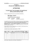
Step 3 uu
Go to the procedure on page 2-3 of the System 4xi User’s Manual to remove the System 4xi
cover. Then go to page 2-4 for instructions on configuring the Main Controller board. The
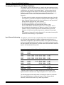
following table and diagram are to be used only as examples of a typical configuration. Please
consult either the label inside the System 4xi top cover or the System 4xi Projector
Communications Kit instructions for the correct configuration settings. Continue with Step 4
below when your configuration is correct.
Config
as
Projector
SW1: 1-2-3-4
SW2
✔
Your Model
off-on-off-on
0
SW3
1
SW4
SW5
SW6
0
5
0
Prj Cable
J15
Comm
Adapter
26-467-01
SW4
SW3
SW5
SW2
J15
SW1
2
3
4
tt
1
SW6
Step 4 uu
Double-check your work and be sure the System 4xi cover is back on securely.
tt
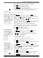
Step 5 uu
Please refer to the appropriate connection diagram for your projector (see your System 4xi
Projector Communications Kit instructions). Using the appropriate Communications Adapter
included in your Communications Kit, connect the Comm extension cable from the PJ Comm
port of the System 4xi to the Comm Adapter. Secure the Comm Adapter to the appropriate
projector port.
tt
Step 6 uu
Connect the RGBS/HV cable from the System 4xi output BNC connectors to the projector’s
matching RGBS/HV input connectors. Verify that all your connections are correct. If in
doubt, please refer to the specific installation instructions which were included in your
Communications Kit.
Extron • System 4xi Switcher Series • User’s Manual
Contents
Extron • System 4xi Switcher Series • User’s Manual
Contents
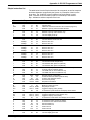
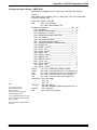
CONTENTS
Chapter One - System 4xi Series - Introduction and Features
Introduction to System 4xi ....................................................................................................... 1-1
System 4xi Features .................................................................................................. 1-2
Specifications .......................................................................................................................... 1-4
Chapter Two - Configuration and Installation
Rear Panel Connectors and Indicators ................................................................................... 2-1
Projector/Monitor Applications................................................................................................. 2-2
Communications Adapters and Cables ...................................................................... 2-3
User-Supplied Cables ................................................................................................ 2-3
Removing the System 4xi Cover ............................................................................................. 2-3
Setting the Main Controller Board for the Projector ................................................................. 2-4
Cabling a System 4xi in a Rack ............................................................................................... 2-5
Audio Terminal Connections ................................................................................................... 2-6
Audio Wiring Applications ........................................................................................... 2-6
Chapter Three - Using the System 4xi Front Panel
Front Panel ............................................................................................................................. 3-1
Main Power ................................................................................................................ 3-1
Inputs ......................................................................................................................... 3-1
Display Controls ......................................................................................................... 3-1
Picture Controls ......................................................................................................... 3-1
Breakaway ................................................................................................................. 3-1
Audio Mute ................................................................................................................. 3-1
Menu Controls ............................................................................................................ 3-1
LCD Display ............................................................................................................... 3-1
Default LCD Screen ................................................................................................................ 3-2
System 4xi Model Differences ................................................................................................. 3-2
Menu Controls and Navigation ................................................................................................ 3-3
Terms used in LCD Menus ......................................................................................... 3-3
Example of Using the Menu Controls ......................................................................... 3-4
Menu System ............................................................................................................. 3-7
Menu Select/Exit Menu ................................................................................. 3-7
Video Mode Configuration ............................................................................. 3-7
Video Mode Configuration Menu ................................................................... 3-7
Audio Level Configuration Menu ................................................................... 3-8
Host Baudrate Menu ..................................................................................... 3-8
RGB Delay Menu .......................................................................................... 3-8
Slave Configuration Menu ............................................................................. 3-9
LD Sync Configuration Menu ........................................................................ 3-9
Sync Configuration Menu .............................................................................. 3-9
Information Menu ......................................................................................... 3-10
Slave Switcher Input Selection ..................................................................... 3-10
Picture Controls (line-doubler/line-quadrupler converter) ....................................................... 3-10
Horizontal Shift Control ............................................................................................. 3-11
Contrast Control ........................................................................................................ 3-11
Color Control ............................................................................................................. 3-11
Tint Control ............................................................................................................... 3-11
Detail Control ............................................................................................................ 3-11
Extron • System 4xi Switcher Series • User’s Manual
i
Contents
System 4xi Series LCD Menus .............................................................................................. 3-12
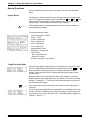
Special Functions .................................................................................................................. 3-13
System Reset ........................................................................................................... 3-13
Toggle Executive Mode ............................................................................................. 3-13
Chapter Four - Connecting Multiple Switchers
Looping the System 4xi with Other Switchers ......................................................................... 4-1
Input Channel Addressing .......................................................................................... 4-1
Controlling Master/Slave Switchers ............................................................................ 4-2
System 4xi with SW4/6 ARMX Switchers ................................................................... 4-3
System 4xi with One System 8/10 PLUS Switcher ....................................................... 4-4
System 4xi with Multiple System 8/10 PLUS Switchers ................................................ 4-5
System 8/10 Plus Switch Settings .............................................................................. 4-6
Programming the System 4xi Looping Configuration .............................................................. 4-7
Testing the Master/Slave Communications ................................................................ 4-7
Chapter Five – Using Windows® Control Software
Extron System Switcher Control Software .............................................................................. 5-1
System 4xi Help (examples) ....................................................................................... 5-2
Executive Mode ......................................................................................................... 5-4
Window Pull-Down Menus ......................................................................................... 5-4
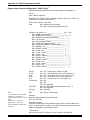
Appendix A - RS-232 Programming Guide
Programming the System 4xi Series Switchers ....................................................................... A-1
RS-232 Connections .................................................................................................. A-1
RS-232 Protocol ........................................................................................................ A-1
Program Instruction Levels ........................................................................................ A-1
System 4xi-Initiated Messages ............................................................................................... A-2
Simple Instruction Set ............................................................................................................. A-3
Related Terms ............................................................................................................ A-3
Simple Instruction List (with examples) ...................................................................... A-4
Simple Instruction Examples ...................................................................................... A-5
Selecting Inputs Using Delimiters ............................................................................... A-7
Advanced Instruction Set ........................................................................................................ A-8
Advanced Instruction List ........................................................................................... A-8
Error Codes (ERC) .................................................................................................... A-8
Hex, Decimal and Binary Examples for Converting Range Values ............................. A-9
Select Input - CMD4 (34h) ......................................................................................... A-9
Request Status - CMD5 (35h) ................................................................................... A-10
Change System Settings - CMD6 (36h) .................................................................... A-11
Set Slave Configuration - CMD8 (38h) ...................................................................... A-11
Configure an Input Channel - CMD9 (39h) ................................................................ A-12
Request Input Channel Configuration - CMD10 (3Ah) .............................................. A-13
Configure System - CMD11 (3Bh) ............................................................................. A-14
Request System Configuration - CMD12 (3Ch) ........................................................ A-15
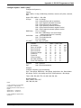
Appendix B - General Reference Information
System 4xi Related Parts List ................................................................................................. B-1
Changing the Main Fuse ......................................................................................................... B-2
Les câbles fournis à l’utillsasteur ............................................................................................ B-3
(French) Enlever le couvercle du Système 4 .......................................................................... B-3
Câbler un Système 4 sur un rack ............................................................................................ B-4
(German) Entfernung der System 4 Abdeckung ..................................................................... B-5
ii
Extron • System 4xi Switcher Series • User’s Manual
Contents
Verkabelung vom System 4 innerhalb eines Gestells ............................................................. B-6
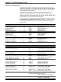
Upgrading Main Controller Board Software and Battery Replacement .................................... B-7
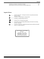
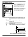
Legend of Icons
_________ Important information – for example, an action or a step that must be done
before proceeding.
_________ A Warning – possible dangerous voltage present.
_________ A Warning – possible damage could occur.
_______ A Note, a Hint, or a Tip that may be helpful.
________ Possible Electrostatic Discharge (ESD) damage could result from touching
electronic components.
________ Indicates word definitions. Additional information may be referenced in another
section, or in another document.
Extron’s System 4xi User’s Manual
68-162-01
First edition – Rev A, 59-07
Second edition – Rev B, 79-02
Third edition – Rev C, 99-12
New format without projectors
Extron • System 4xi Switcher Series • User’s Manual
iii
Contents
Extron • System 4xi Switcher Series • User’s Manual
System 4xi Switcher Series
User’s Manual
1
Chapter One
Introduction and Features
System 4xi Features
Projector/Monitor Applications
RGB Decoder, Line Doubler and Line Quadrupler
Specifications
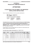
Chapter 1 • Introduction and Features
Introduction to System 4xi
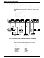
EXTRON’S System 4xi Series of switchers (henceforth to be referred to as System
4xi ) combines the features of a projector-controlling switcher and a line-doubler
or line-quadrupler into a rack-mountable enclosure with an internal power supply.
The System 4xi ’s four video inputs can be any combination of the formats listed
below and the output will always be RGB. Four stereo audio inputs are also
available and can be selected following or separated from the selected video
input.
•
•
•
•
•
•
INPUT 1
H/HV
R/C
Composite Video (NTSC/PAL)
S-video/S-VHS (YC)
RGBS (NTSC/PAL)
RGBS (RGB w/separate composite sync)
RGsB (RGB w/sync on green)
RGBHV (RGB w/separate H&V sync)
INPUT 2
V
G/Y
AUDIO
B
H/HV
R/C
INPUT 3
V
G/Y
AUDIO
B
INPUT 4
H/HV
R/C
V
G/Y
AUDIO
B
H/HV
R/C
OUTPUT
V
G/Y
AUDIO
PJ COMM
B
H/HV
RS 232
V
R/C
AUDIO
G/Y
B
RGB
Interface
Laserdisc Player
with S-VHS Outputs
and Stereo Audio
PC or Workstation
with Audio
RGB
Interface
SGI/SUN
Workstation
Control
System
VCR/VTR with Audio
Stereo Audio
Large Screen
Projector
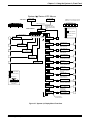
Figure 1-1. Example of a System 4LDxi Switcher with Input and Output Devices
The System 4xi has a built-in communications interface that allows it to control
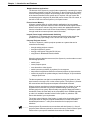
projectors made by companies listed below through their switcher control port.
Please consult Extron for projector manufacturers not listed here.
•
•
•
•
•
•
•
•
1-1
Ampro
Barco
Digital Projection
Eiki
Electrohome
Hughes/JVC
Infocus
Mitsubishi
•
•
•
•
•
•
•
•
NEC/Runco
Panasonic
Sanyo
Seleco
Sharp
Sony
Toshiba
Zenith
Extron • System 4xi Switcher Series • User’s Manual
Chapter 1 • Introduction and Features
System 4xi Features
Universal Video Inputs
The System 4xi has four universal inputs, each capable of accepting all computer
RGB signals from 15 kHz to 150 kHz, any composite video standard signals
(NTSC or PAL) and S-video (S-VHS) signals. There are no optional modules to
purchase for each input signal type.
Quad-standard Decoder
The System 4xi is compatible with all standard video formats including NTSC
3.58, NTSC 4.43, PAL and SECAM.
Balanced/Unbalanced Audio Inputs
Every System 4xi is capable of switching up to four balanced or unbalanced, left
and right stereo audio signals. Audio, input through professional-style captive
screw connectors, can be switched to follow any video or RGB input signal, or it
may be switched separately for added flexibility (see “Breakaway” below).
Audio Follow/Breakaway
When switching inputs, the System 4xi can either select audio and video from the
same source (Audio Follow) or select audio from one source and video from
another (Breakaway).
Three-line Adaptive Comb Filter
A built-in, three-line adaptive comb filter helps to provide a crisp, stable output
from the System 4LDxi and 4LQxi.
Built-In Line Doubler/Quadrupler (scan doubler/quadrupler)
The System 4LDxi and 4LQxi include a built-in NTSC or PAL compatible line
doubler or line quadrupler (4LQxi only) that is capable of line-doubling/
quadrupling composite video, S-video or RGB video (Targa or document
camera) signals. The signal also passes through a digital noise filter to improve
the picture. The line-doubled/quadrupled output results in a sharper image with
less noticeable scan lines and “video noise.”
300 MHz RGB Video Bandwidth
The 300 MHz RGB video bandwidth of the System 4xi makes it two to three
times the performance of any other presentation switcher.
LCD Menu-Driven Picture and Programming Controls
The System 4LDxi ’s LCD menu makes setup and programming of its features
and functions easy and flawless. An alphanumeric display allows for any of the
line-doubler/quadrupler controls such as color, hue and contrast to be adjusted
to exact specifications for each input.
RGB Output
The System 4xi video output will be RGBS or RGBHV if the selected input is
configured to be line-doubled or line-quadrupled. If the selected input is not
configured to be line-doubled/quadrupled, the output video format will be the
same as the input.
RS-232 Control
The System 4xi has built-in RS-232 control for external/third party control of any
of its features or functions.
Triple-Action Switching™ RGB Delay Switching
Triple-Action Switching makes it possible to have “seamless” picture switching.
The System 4xi may be programmed to switch the RGB signals to the projector
at a specified time after the sync is switched (0 to 5 seconds, in 1/2 second
increments). The audience will briefly see a blank screen while the projector
“locks on” to the input signal.
Extron • System 4xi Switcher Series • User’s Manual
1-2
Chapter 1 • Introduction and Features
Multiple Switcher Applications
The features of the System 4xi can be further expanded by connecting the output
from another switcher to Input #4. The System 4xi then functions as the “master”,
communicating with the projector and providing it with a signal improved by any
of the features described in this section and, if required, can even control the
connected projector using their IR (Infra-Red) remote control, RS-232 control, or
the built-in LCD menu-driven System 4xi front panel control.
Picture Control Memory
All inputs, including those in multiple switcher applications, have a separate
memory block for all picture controls of video or RGB and audio signals. When a
different video input is selected, the picture controls are updated automatically
from the information stored in the Picture Control Memory. RGB inputs in passthrough mode have no stored picture control information.
Internal Power Supply with Automatic Switching
The System 4xi is equipped with an internal auto-switching power supply that
operates from any input voltage in the 100-240 VAC range, at 50/60Hz.
Universal Projector Control
The EXTRON System 4xi and the projector operate as a system that can be
controlled several ways:
•
•
•
•
through existing projector controls
through the System 4xi panel
through a host system using the RS-232 port
using Extron’s Windows® Control software
Using the projector-brand remote control, the System 4xi can be made to control
the following operations:
•
•
•
•
•
•
switch inputs
control projector power
mute the audio or video signals
switch input memory blocks (in projector) for convergence
setup saved configurations within the connected projector by input selection
monitor the projector for update changes, feature changes, or input selection
changes by the user
The above operations can also be accomplished by using the System 4xi front
panel controls or through a PC or other control system. The System 4xi switcher
will communicate with the projector and pass it the desired command.
When a projector manufacturer introduces a new model, the System 4xi can be
upgraded to accommodate it by a simple EPROM change (free during the
warranty period of two years). When a totally new projector brand and model is
introduced, Extron will either add it to the compatibility list for EPROM upgrades,
or make it an available “standard” with all future System 4xi switchers. Call
Extron with details of your requirements.
The unique control features of the System 4xi make using its switcher functions
exactly the same as using the projector-brand switcher, but with a 300 MHz
bandwidth performance — nearly three times that of most projector- brand
switchers.
_______ Some projector IR remotes do not communicate with the System 4xi. Also, all
projectors have different methods for source and memory recall of source inputs.
Please refer to your specific installation instructions for further details.
1-3
Extron • System 4xi Switcher Series • User’s Manual
Chapter 1 • Introduction and Features
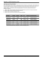
Specifications
Video input
Number/type ..............................
Connectors ................................
Nominal level(s) ........................
Maximum level(s) ......................
Impedance ................................
Horizontal frequency .................
Vertical frequency .....................
Return loss ................................
4 universal inputs (RGBHV, RGBS, RGsB, RsGsBs, S-video, composite video)
4 x 5 BNC female
Analog — 0.3V to 1.45V p-p
Analog — 2V p-p
75 ohms (deselected inputs)
15 kHz to 150 kHz
30 Hz to 150 Hz
-30dB @ 5 MHz
Video throughput
Gain ...........................................
Bandwidth .................................
Crosstalk ...................................
Switching speed ........................
Unity
300 MHz (-3dB)
-80dB @ 3.58 MHz
5 mS (max.)
Video output
Number/type/format .................. System 4LDxi ................... 1 RGBHV, RGBS, RGsB, line-doubled video
System 4LQxi ................... 1 RGBHV, RGBS, RGsB, line-quadrupled video
Connectors ................................ 5 BNC female
Nominal level ............................ 1V p-p
Impedance ................................ 75 ohms
Return loss ................................ -25dB @ 10 MHz
DC offset ................................... ±5 mV maximum
Switching type ........................... Triple action, 0 S to 5 S, adjustable
Sync
Input type ..................................
Output type ................................
Standards ..................................
Input level ..................................
Output level ...............................
Input impedance .......................
Output impedance .....................
Max input voltage ......................
Max. propagation delay ............
Max. rise/fall time ......................
Polarity ......................................
RGBHV, RGBS, RGsB, RsGsBs
RGBHV, RGBS, RGsB, RsGsBs
NTSC 3.58, NTSC 4.43, PAL, SECAM
0.5V to 5V p-p
0.5V to 5V p-p
510 ohms (deselected inputs)
75 ohms
5V p-p
5 nS
5 nS
Positive or negative (follows input)
Audio input
Number/type .............................. 4 stereo, balanced/unbalanced
Connectors ................................ 4 5 mm captive screw terminals, 6 conductor
Impedance ................................ Unbalanced ...................... 10 kohms, AC coupled
Balanced .......................... 20 kohms, AC coupled
Maximum level .......................... +11.2dBu, (balanced or unbalanced) @ stated %THD+N
Input gain adjustment ............... –95.5dB to +31.5dB, adjustable per input
Audio throughput
Frequency response .................
THD + Noise .............................
S/N ............................................
Adjacent input crosstalk ............
Stereo channel separation ........
CMRR ........................................
±0.05dB @ 20 Hz to 20 kHz
0.002% @ 1 kHz at rated maximum output drive
>95dB
>85dB @ 20 Hz to 20 kHz
>60dB @ 20 Hz to 20 kHz
>60dB @ 20 Hz to 20 kHz
Extron • System 4xi Switcher Series • User’s Manual
1-4
Chapter 1 • Introduction and Features
Audio output
Number/type ..............................
Connectors ................................
Impedance ................................
Gain error ..................................
Drive (HI-Z) ...............................
Drive (600 ohm) ........................
1 stereo, balanced/unbalanced
5 mm captive screw terminal, 6 conductor
50 ohms, unbalanced; 100 ohms, balanced
±0.2dB channel to channel
> +17.2dBu, balanced or unbalanced at stated %THD+N
> +17.2dBu, balanced or unbalanced at stated %THD+N
Control/Remote — switcher
Serial control port ......................
Baud rate and protocol .............
Pin configurations .....................
Program control ........................
RS-232, 9-pin female D connector
9600, 8-bit, 1 stop bit, no parity
2 = TX, 3 = RX, 5 = GND
Extron’s Windows® control program
Extron’s Simple Instruction Set - SIS
Extron’s Advanced Instruction Set - AIS
Control — projector
Projector control port ................ 1 15-pin HD female connector
General
Power ........................................ 100VAC to 240VAC, 50/60 Hz, 20 Watts, internal, auto-switchable
Temperature/humidity ............... Storage -40° to +158°F (-40° to +70°C) / 10% to 90%, non-condensing
Operating +32° to +122°F (0° to +50°C) / 10% to 90%, non-condensing
Rack mount ............................... Yes, with attached rack ears
Enclosure type .......................... Metal
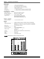
Enclosure dimensions ............... 1.75" H x 19" W x 16.2" D
4.4 cm H x 48.3 cm W x 41.2 cm D
Shipping weight ........................ 17 lbs (7.7 kg)
DIM weight ....................... 21
Vibration .................................... NSTA 1A in carton (National Safe Transit Association)
Approvals .................................. UL, CUL, CE
MTBF ......................................... 30,000 hours
Warranty .................................... 2 years parts and labor
Specifications are subject to change without notice.
19.0"
1-5
Extron • System 4xi Switcher Series • User’s Manual
System 4xi Switcher Series
User’s Manual
2
Chapter Two
Configuration and Installation
Rear Panel Connectors and Indicators
Projector/Monitor Applications
Removing the Cover
Setting the Main Controller Board
Rack Mounting
Audio Connections
Connecting to Projectors/Monitors
Chapter 2 • Configuration and Installation
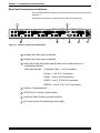
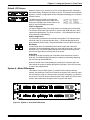
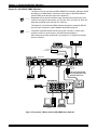
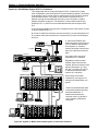
Rear Panel Connectors and Indicators
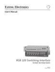
Use the diagram below to locate the connectors and indicators on the back of the
System 4xi.
All models of the System 4xi Series have the same rear panel layout.
1
4
INPUT 1
H/HV
R/C
INPUT 2
V
G/Y
AUDIO
B
H/HV
R/C
INPUT 3
V
G/Y
AUDIO
B
H/HV
R/C
INPUT 4
V
AUDIO
G/Y
B
H/HV
R/C
2
OUTPUT
V
G/Y
AUDIO
B
3
PJ COMM
H/HV
RS 232
V
R/C
5
AUDIO
G/Y
B
6
7
Figure 2-1. System 4xi Rear Panel Identification
1
Indicates this Audio Input is selected
2
Indicates this Video Input is selected
3
Audio (left & right) and Video Input #4 (also used for Slave input in a
multiswitcher system)
Video Input formats:
Composite Video — use G connector
S-video — use C & Y connectors
RGsB — use R, G & B connectors
RGBS — use R, G, B & HV connectors
RGBHV — use R, G, B, H & V connectors
2-1
4
Projector Communications
5
RS-232 port for control by host system
6
Audio and Video Output to projector/monitor
7
AC Power input to Autoswitching power supply
Extron • System 4xi Switcher Series • User’s Manual
Chapter 2 • Configuration and Installation
Projector/Monitor Applications
The System 4xi can be configured for most projectors. Some of the projector
manufacturers that Extron supports are:
•
•
•
•
•
•
•
•
•
Ampro
Barco
Digital Projection
Eiki
Electrohome
Epson
Digital Projection
Hughes/JVC
Infocus
•
•
•
•
•
•
•
•
Mitsubishi
NEC
Panasonic
Seleco
Sharp
Sony
Toshiba
Zenith
If your projector manufacturer is not on the above list, please consult your Extron
representative.
_______ Because this manual is for the System 4xi Series switchers, the name “System
4xi ” will be used except when referring to a specific model.
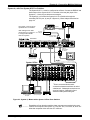
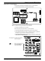
The following diagram is a typical example of System 4xi-to-projector cabling.
However, before connecting the cables, verify that the System 4xi is already
configured for your projector/monitor.
2-Channel
Stereo Audio
Rear Panel
INPUT 1
H/HV
R/C
INPUT 2
V
G/Y
AUDIO
B
H/HV
R/C
INPUT 3
V
G/Y
AUDIO
B
H/HV
R/C
INPUT 4
V
G/Y
AUDIO
B
H/HV
R/C
OUTPUT
V
G/Y
AUDIO
B
PJ COMM
RS 232
H/HV
V
R/C
AUDIO
G/Y
B
Projector Communication
Extension Cable
BNC Cable
Projector
Comm Adapter
Projector
Figure 2-2. System 4xi Outputs. A factory label identifies the configuration.
Configuring the System 4xi for your application requires the following major steps
using the System 4xi Projector Communications Kit instructions for your specific
projector or monitor:
Extron • System 4xi Switcher Series • User’s Manual
2-2
Chapter 2 • Configuration and Installation
1. The System 4xi must be configured internally for the projector/monitor to be
used. This is done at the factory when the unit is ordered, and a label is placed on
the rear panel to identify the configuration. However, there may be times when the
configuration must be changed for a different application.
2. Place, or mount, each piece of equipment in the location where it will be used.
3. Connect the cables and adapter between the System 4xi and the projector.
4. Connect other equipment, such as audio or various controlling devices.
5. Set up the projector, using the manual(s) provided by the manufacturer.
_______ There are procedures in this chapter for installation of specific projectors to the
System 4xi. Use the appropriate procedure for your application.
Communications Adapters and Cables
Because there are projector differences, Extron makes communication adapters
for the projector types listed on the previous page.
Each System 4xi package includes the following:
•1
•1
•1
•5
•1
•1
System 4xi (factory-configured for the customer)
Comm Adapter (specified by the customer)
CC 50' Projector Communications Extension cable
Audio connectors with captive screws (audio cables not included)
AC Power Cord
Tweaker (combination screwdriver)
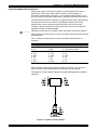
User-Supplied Cables
For custom installations, you may choose to make your own Projector
Communication cables (CC-xx'). Refer to the cable wiring diagram below for pin
connections. Cables may be up to 200' in length.
15-pin D-Sub
High Density
Female
Extron System 4xi
Switcher
9-pin
D-Sub
200 Feet (max)
1
2
3
4
5
6
7
8
9
1
2
3
4
5
6
7
8
Female
Extron
Communications
Adapter
15
Figure 2-3. Communications Cable Wiring Diagram
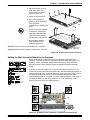
Removing the System 4xi Cover
If the System 4xi must be reconfigured for a different display device, it is
necessary to access the Main Controller board. Also, if the main power fuse
needs to be changed, you will need to access the inside of the unit. To do either
of these two things, you must first remove the top cover of the System 4xi, as
follows:
1. Unplug the AC power cord.
2. If rack-mounted, remove the System 4xi from the mounting rack.
3. Label the input and output cables and remove them.
2-3
Extron • System 4xi Switcher Series • User’s Manual
Chapter 2 • Configuration and Installation
4. Place the System 4xi on a
clean work space and
remove eight (8) screws
shown in Figure 2-4.
5. Lift the cover straight up.
6. Go to the procedure for
which you have opened the
cover (projector
configuration or changing the
fuse).
_____ Do NOT touch any switches
or electronic components,
other than those specified.
This could seriously affect
the operation of the system.
7. Reverse this procedure
when finished working
inside the System 4xi.
(French) Enlever le couvercle du Système 4xi - page B-3
Configuration
Label Inside
(German) Entfernung der System 4xi Abdeckung - seite B-5
Figure 2-4. Removing the System 4xi Cover
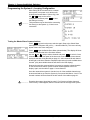
Setting the Main Controller Board for the Projector
Before each System 4xi ships, it is set for the application specified by the
customer. The projector name is on a label on the rear panel (see Figure 2-1).
However, if there is a need to change these settings (e.g. using a different
projector/monitor), switch settings must be changed on the Main Controller
board.
[System 4xi model and software
version displayed here]
(See note.)
(See note.)
(See note.)
(See note.)
(Note: Information depends on
System 4xi setup.)
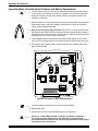
1. If you are not sure if the System 4xi is set for your projector/monitor, use the
Front Panel to select the Information Menu (#8), and then display the System 4xi
settings (see page 3-10). A general example is shown to the left. Refer to Figure
2-5 below as an example only to locate the switches and projector cable.
Configuration information is located on a label inside the System 4xi top cover. If
the projector cable is on the wrong connector, or if DIP switches (1-4) are
incorrect, this error will not be seen in Menu 8.
SW4
SW3
SW5
SW2
J15
SW1
1
2
3
SW6
4
ON
Figure 2-5. Example of Setup Switches on the Main Controller Board
Extron • System 4xi Switcher Series • User’s Manual
2-4
Chapter 2 • Configuration and Installation
2. If your unit is not set up correctly, remove the System 4xi cover (page 2-3) and
locate the switches and projector connectors. Note the orientation of the SW1
switches in the picture. “On” is marked on the DIP switch block.
3. Set the switches as indicated by the label or the instructions included with the
projector communications kit and verify that the Projector cable is on the correct
connector (J9/J15).
_______ Extron continues to support new projectors. If you have questions about using
the System 4xi with a device for which you cannot find configuration settings,
please consult with your Extron representative.
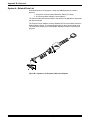
4. Refer to the appropriate cabling procedure included with the projector
communications kit to continue the installation.
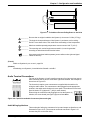
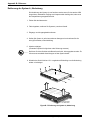
Cabling a System 4xi in a Rack
When routing cables from one unit to another in a rack, do NOT allow the cables
to be supported by the System 4xi (see Figure 2-7). Use “Tie Wraps”, “Rip-Ties”
or other devices, to secure the cables at some point in the rack that is above the
rear panel connectors. Loosely hanging cables may be stepped upon, resulting
in damage to cables and equipment, as well as injury to personnel.
The example shown in Figure 2-6 has the cables tied to the rack above the
connections to the equipment. This allows an unobstructed view of the rear panel
connectors, and prevents the cable weight from pulling down on the equipment.
Figure 2-6. Route the Signal Cables on the Left and Power Cables on the Right
2-5
Extron • System 4xi Switcher Series • User’s Manual
Chapter 2 • Configuration and Installation
Figure 2-7. Tie Cables to Prevent Pulling Down on the Units
_________ Be sure that no weight is added to the System 4xi in excess of 10 lbs (3.73 kg).
_________ The holes in the top and bottom of the System 4xi enclosure are for cooling.
Do NOT cover these holes. This could cause overheating of vital components.
_________ Maximum ambient operating temperature must not exceed 104° F (40° C).
_________ The mounting rack, and all equipment mounted in it, must be grounded
according to national and local electrical codes.
_______ Keep power and signal cables separate (power cables on the right and signal
cables on the left.)
(French)
Câbler un Système 4xi sur un rack - page B-4
(German)
Verkabelung vom System 4xi innerhalb eines Gestells - seite B-6
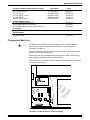
Audio Terminal Connections
The rear of the System 4xi has five audio connectors (four input and one output).
Each connector has six pins for a left and a right audio channel. One example is
shown here in Figure 2-8.
The 6-terminal, captive screw connectors are supplied with the switcher for
wiring the audio cables. The connectors are then plugged into the appropriate
position in the audio terminal strip on the rear panel. The audio area of the back
panel is labeled “R” (right) and “L” (left) for each channel.
When wiring the connectors and plugging them into the System 4xi
switcher, the screw heads (see figure right) must face down.
Figure 2-8. Captive Screw Audio Connectors (above and right)
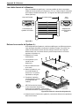
Audio Wiring Applications
Three methods of wiring the connectors for input and output are listed here, and
illustrated in Figure 2-10. (The connector screws do not show in Figure 2-10
because they are on the other side.)
Extron • System 4xi Switcher Series • User’s Manual
2-6
Chapter 2 • Configuration and Installation
• Unbalanced High Impedance (High Z) Stereo Tip, Ring, Ground (Left & Right)
• Balanced High Impedance (High Z) Stereo Tip, Ring (Left & Right)
• Balanced 600W input Impedance Stereo Tip, Ring (Left & Right)
TIP +
RING
-
TIP RING
TIP
SLEEVE
SLEEVE
SLEEVE
Figure 2-9. The Audio Cable Equivalent Connections
Figure 2-10. Three ways to Wire the Input and Output Audio Connectors
_________ If using unbalanced audio output, use lower-left connector as an example, and
connect the sleeve to Gnd. Connecting it to the negative (-) terminal will damage
audio output circuits.
_______ Use captive-screw audio connectors, Extron part number 10-163-01
2-7
Extron • System 4xi Switcher Series • User’s Manual
System 4xi Switcher Series
User’s Manual
3
Chapter Three
Using the System 4xi Front Panel
Front Panel Buttons and Indicators
Picture Controls for Line Doubler and Line Quadrupler
Examples for Using Some of the Menus
Using Menus to Make Adjustments
Using Menus to Configure the System
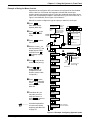
Figure 3-1. System 4LDxi Front Panel (other System 4xi Series front panels are very similar)
MAIN POWER
BREAKAWAY
This button turns the System 4xi power On or Off. The light indicates when
power is On.
The Breakaway button allows the audio and video signals to be separated
from (Breakaway) or combined with (Follow) each other to the output. There
are three choices: Video & Audio, Video only or Audio only. The current
condition is displayed in the LCD panel by arrows on the left side.
INPUTS
Inputs (1 thru 4) buttons are used to select which of the four possible inputs
will go to the output (projector or monitor).
_ In Executive mode (explained later) audio always follows video.
DISPLAY CONTROLS
POWER - allows the connected display power to be turned On or Off from the
System 4xi. The LED lights when power is On.
AUDIO MUTE
Extron • System 4xi Switcher Series • User’s Manual
MUTE - commands the attached display picture to be muted (blanked). The
LED is lighted when the picture is being muted.
This button allows the audio to be muted (temporarily turned off). When
Audio is muted, the LCD panel alternately displays the word "Muting" and
then the current dB level.
PICTURE CONTROLS (depends upon the System 4xi model)
MENU CONTROLS
These buttons only affect line-doubled/quadrupled signals, as well as
decoded composite and S-video signals. (Functions marked with ‡ do not
affect line-doubled/quadrupled RGB.) When pressed, each button brings up
an LCD display which is used with Menu Controls to make adjustments.
The Menu Control buttons are used with the LCD screen to display and
make changes to system settings.
H SHIFT - brings up an LCD display for Horizontal Shift adjustment. This
allows the picture to be adjusted left or right.
CONT - (‡) brings up an LCD display for adjusting the picture Contrast.
COLOR - (‡) brings up an LCD display for adjusting the Color level.
TINT -
(‡) brings up an LCD display for adjusting the Tint or Hue.
DETAIL - (‡) (only on 4LDxi /ex and 4LQxi /ex models) brings up an LCD
display to adjust up to 4 levels of picture Detail (sharpness).
_ After making an adjustment, press the same Picture Control button
to save the setting and exit from the display.
_ The Up and Down buttons are used to change a selection or a value
in the LCD display.
____ The Tab button is used to step from one selection point to the next
on the LCD display.
(Button combinations are used for special functions – explained later.)
_ The Menu button is used to display a Select menu, which is used to
select other control menus.
The Enter button is used to enter a menu sequence, save a setting
and/or complete an operation.
LCD DISPLAY
The LCD screen displays System 4xi status and is used interactively with
front panel buttons when making changes to settings.
Chapter 3 • Using the System 4xi Front Panel
3-1
Front Panel (4LDxi model shown) Controls are described beginning from the left side.
Chapter 3 • Using the System 4xi Front Panel
Default LCD Screen
When the System 4xi is powered up, a Title screen appears briefly, followed by
the Default display. Examples are shown to the left. This manual covers different
System 4xi models; an appropriate screen will appear displaying your model and
software version.
The Default screen (shown to the right) will
continue to display whenever the panel is not
being used. It displays the current status of the
input(s), with the following information:
Video Configuration
The top line displays which video input channel is selected and its Video Mode.
The example shows that Video input #1 is selected, with RGB and Sync. Other
modes are explained later. The Arrow to the left (® VID) indicates that video is
being switched (not Breakaway).
Audio Configuration
The second line provides the current audio configuration. The example shows
that Audio input #1 is selected and the arrow (® AUD) indicates that audio is
being switched (Audio Follow). The gain/attenuation is set at 0 dB for that input.
Breakaway
As mentioned earlier, the Breakaway button allows Audio and Video to be
separated. The three breakaway steps are: Video and Audio (both), Video only,
and Audio only. The Default Display indicates this condition by turning off the
arrow for the signal that is not being sent to the output.
Audio Mute
As stated on the previous page, the Audio Mute button temporarily turns the
audio Off. The Default Display indicates this condition by alternately displaying
the word "Muting" and the dB level.
When the default menu is being displayed, pressing a Front Panel button will
then change the screen to display appropriate information. These LCD screens,
or menus, are explained later.
System 4xi Model Differences
This chapter covers all both System 4xi models. Each model has different
features, and a different Front Panel. Because the System 4LDxi and 4LQxi have
the most features, page 3-1 shows a 4LDxi front panel; all System 4xi panels are
shown below. The most obvious differences are in the number of Picture Control
buttons. Other differences will appear when using the LCD menus.
Figure 3-2. System 4xi Front Panel Differences
Extron • System 4xi Switcher Series • User’s Manual
3-2
Chapter 3 • Using the System 4xi Front Panel
Menu Controls and Navigation
Figure 3-7 on page 3-12 shows a flowchart of all the menus. Use it as a road
map or guide to get to a specific one.
There are two groups of menus. There is a menu for each of the Picture Control
buttons on the front panel. These are explained on page 3-12 . The larger portion
of the flow diagram is a network of menus for setting up (or displaying) the
System 4xi input and output configuration, and are selected from the five Menu
Control buttons on the Front Panel (shown above). The text and diagrams in this
section include symbols that represent these panel buttons. They are: , , ,
and
The Menu Control buttons are used with the LCD screen for viewing status,
changing settings, and making adjustments to the System 4xi configuration.
Each menu is described later. The Menu button (
) is the starting point.
_______ Press
at any time to leave a menu and return to the Select/Exit menu.
The LCD menus include "Help" symbols to indicate how to use them. An
example of these symbols can be seen in the menus to the left. Their
descriptions are as follows:
• The arrows in the upper-right corner (® ¯ ) of the display indicate which of
the direction buttons,
, may be used with this menu. These buttons
allow the user to step forward, backward, or loop through menu choices.
• The character " >" marks a selection point where the user may choose
between two or more options. For menus that have more than one selection
point, use the
button to step from one selection point to the next (and then
loop back to the first).
or
to change the display to
• The character "_" is the cursor position. Use
the right of the cursor and make a different selection. When a function blinks,
that indicates a tentative decision. That is, you have displayed something,
but have not yet made the selection. Press
to select and save it. If a
function does not blink, it is already selected, or active.
_______ To exit a Control Menu at any time, without saving changes, press any of the
four input buttons to return to the Default menu. (If you don’t want to change
input selections, press the button for the input that is already selected.)
Terms used in LCD Menus
AUD = Audio
CHL = Input channel (used in Menu #9). It includes both Audio and Video.
CFG = Configuration, as in setup
H = Horizontal, as in horizontal sync
H/V = Horizontal and Vertical, as in composite sync (H and V)
LD = Line-doubled output (LQ = Line-quadrupled output)
RGB = Red, Green and Blue colors or video signals
RGsB = Red, Green and Blue, and the sync included with the Green signal
RGBS = Red, Green and Blue, and the Sync (H and V) on a 4th line
Slave = Another switcher whose output serves as an input to a System 4xi.
_m = Motion - use this for video with action.
_s = Still - use this for text or still pictures (slide presentations)
VID = Video
YC = S-Video, for the chrominance (C) and the luminance (Y)
V = Vertical, as in vertical sync
_______ The following pages have examples for using some of the menus, as well as
details on the function of each menu. Page 3-12 (Figure 3-7) has a flowchart of
the LCD menus. You may use it as a road map to go from one menu to another.
3-3
Extron • System 4xi Switcher Series • User’s Manual
Chapter 3 • Using the System 4xi Front Panel
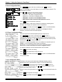
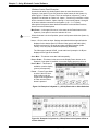
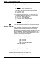
Example of Using the Menu Controls
Suppose we have a System 4LDxi and want to set up Input #2 for line-doubled,
motion video in a VGA format with separate horizontal and vertical sync,
negative polarity and serration pulses. Follow the numbered steps below as you
refer to the corresponding numbers in the flowchart in Figure 3-3 for Menu #1, in
Figure 3-4 for Menu #6, and in Figure 3-5 for Menu #7.
Menu #1 is used to configure the type of output you want from each input.
❶ Press
Enter Menu Select
Options (Menu #0).
SYSTEM 4LDxi
EXTRON V3.11
After 2-3
second
delay
❷ Press
or
to get
Menu #1 (Vid Mode
CFG).
❸ Press
Default
Screen
Power Up
Display
Displayed information
depends upon video
type, audio level and
breakaway setting.
Change Entry Point
->VID 01 RGBS
->AUD 01 +00dB
Change Selection
❶
Accept/Save Selection
to select
this menu.
❹ With the cursor (_) at
the left position (>), the
display shows VID01
selected. Press
or
to display Input #2
(VID02).
❺ Press
to step to the
next selection point (>).
❻ Press
or
to
display RGBLD_m.
(Output will be linedoubled, motion video
for Input #2.)
➐ Press
to save
this setting for Input #2.
Press
to exit this
menu and go to
Menu #0.
❽ From Menu #0
you
may start your next
setup procedure, or
press
to return to
the Default Menu.
_______ A detailed explanation
of each menu follows,
beginning with Menu #0
on page 3-7.
Exit to Menu 0
❽
MENU SELECT
Go to
Menu 9 0.EXIT
❷
➐
❸
MENU SELECT
1.VID MODE CFG
VID MODE CFG
>VID02=>RGBLD_m
❹
MENU SELECT
2.AUD LEVEL CFG
MENU SELECT
3.HOST BAUDRATE
Select
Video
Input #2.
❺
Move cursor.
Select Video Type
>RGBLD_m
❻
This example is for
System 4LDxi.
MENU SELECT
4.RGB DELAY
MENU SELECT
5.SLAVE CFG
MENU SELECT
6.LD SYNC CFG
MENU SELECT
7.LD CFG
MENU SELECT
8.INFORMATION
MENU SELECT
9.SWITCH SLAVE
*Only if configured
as a Slave switcher
Go to
Menu 0
Figure 3-3. Example: Configuring System 4 Inputs
Extron • System 4xi Switcher Series • User’s Manual
3-4
Chapter 3 • Using the System 4xi Front Panel
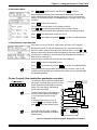
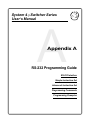
Menu #6 is used to set up composite or separate horizontal and vertical sync for
line-doubled/quadrupled images. Follow the numbers in the diagram and
continue.
❶ Press
❷ Press
to get the Menu Select Options (Menu #0).
or
to get
Menu #6 (LD Sync
CFG).
SYSTEM 4LDxi
EXTRON V3.11
❸ Press
to select
this menu. There are
four functions in this
Default
menu as displayed
from the left selection
point. They are listed in
the diagram. Use
to
move between the two
selection points, and
Go to
then use
or
to
Menu 9
show the choices, and
leave your choice
displayed before going
to the next function.
After 2-3
second
delay
Power Up
Display
Displayed information
depends upon video
type, audio level and
breakaway setting.
Change Entry Point
->VID 01 RGBS
->AUD 01 +00dB
Change Selection
Accept/Save Selection
1
Exit to Menu 0
7
MENU SELECT
0.EXIT
MENU SELECT
1.VID MODE CFG
❹ From the left selection
point, press
or
to
choose one of the four
functions.
MENU SELECT
2.AUD LEVEL CFG
❺ Press
to step to the
second selection point
and press
or
to
change the selection
for that function. If the
display already shows
what you want, leave it
and go on. The
choices made for this
example are circled.
❹ Press
to step back
to the left selection
point. Repeat steps ❹
and ❺ until you have
made all of your
changes to this menu.
MENU SELECT
3.HOST BAUDRATE
MENU SELECT
4.RGB DELAY
MENU SELECT
5.SLAVE CFG
➐ Press
4
Select function and move cursor
4 functions, 2 choices each
2
5
3
MENU SELECT
6. LD SYNC CFG
MENU SELECT
7.LD CFG
Make selection
4
a - Select H/HVOUT =
4
b - Select SERRA. =
4
c - Select HOUT POL =
5
MENU SELECT
8.INFORMATION
5
4
MENU SELECT
9.SWITCH SLAVE
6
LD SYNC CFG
>H/HVOUT=>CSYNC
5
❻ Press
to save
these settings and
press
to go to
Menu #0. From there
you may step to
another menu and start
your next setup
procedure, or exit.
Screen
Select H Only
Select PRESENT
Select NEG
d - Select VOUT POL =
5 Select NEG
*Only if configured
as a Slave switcher
Go to
Men 0
to exit Menu #0 and go to the Default Menu.
Figure 3-4. Example: Configuring System 4 Output Sync for Line Doubled/Quadrupled Sources
_______ A detailed explanation of each menu follows, beginning with Menu #0 .
3-5
Extron • System 4xi Switcher Series • User’s Manual
Chapter 3 • Using the System 4xi Front Panel
Menu #7 is used to set up Demo and VGA modes.
❶ Press
to get the Menu Select LCD (Menu #0).
❷ From Menu #0, press or to go to Menu #7.
❸ Press
to select this menu. There are two functions in this menu as
displayed from the left selection point. They are listed in the diagram. Use
move between the two selection points, and then use
or
to show the
choices, and leave
SYSTEM 4LD
Power Up
your choice displayed
EXTRON V3.11
Display
before going to the
After 2-3
Displayed information
second
depends upon video
next function.
delay
to
xi
❹ From the left selection
point, press
or
to
choose one of the two
functions.
type, audio level and
breakaway setting.
Default
Change Selection
Accept/Save Selection
1
Exit to Menu 0
❺ Press
to step to the
second selection point
or
to
and press
change the selection. If
the display already
shows what you want,
leave it and go on.
Repeat ❹ and ❺ to
make other changes to
this menu. The choices
for this example are
circled.
7
MENU SELECT
Go to
Menu 9 0.EXIT
MENU SELECT
1.VID MODE CFG
MENU SELECT
2.AUD LEVEL CFG
❻ Press
to save
these settings and
press
to go to
Menu #0. From here
you may step to
another menu and start
your next setup
procedure, or exit.
MENU SELECT
3.HOST BAUDRATE
Screen
MENU SELECT
4.RGB DELAY
MENU SELECT
5.SLAVE CFG
➐ Press
to exit
Menu #0 and go to the
Default Menu.
_______ VGA mode is only
available on System
4LDxi.
_______ A detailed explanation
of each menu follows,
beginning with
Menu #0 on page 3-7.
Change Entry Point
->VID 01 RGBS
->AUD 01 +00dB
MENU SELECT
6. LD SYNC CFG
2
4
Select function and move cursor
2 functions, 2 choices each
5
3
MENU SELECT
7.LD CFG
MENU SELECT
8.INFORMATION
MENU SELECT
9.SWITCH SLAVE
Make selection
6
LD CFG
>VGA MODE=>ON
4
a - VGA Mode:
4
b - Split Screen:
5
On or Off
5
On or Off
(demo mode)
*Only if configured
as a Slave switcher
Go to
Menu 0
Figure 3-5. Example: Configuring the System 4xi Line-Doubled
Output to be exactly 640 x 480, standard VGA mode
Extron • System 4xi Switcher Series • User’s Manual
3-6
Chapter 3 • Using the System 4xi Front Panel
0. Menu Select/Exit Menu
The Menu button (
)brings up the Menu Select/Exit screen. This is the
starting point to get into any of the Control Menus. Some menus in this chapter
have more than one example. This is because of the different System 4xi
models. Be sure to use the example for the System 4xi model you are using.
The example here is for the System 4LDxi model (4LQxi is very similar except for
references to line quadrupler).
Press
or
to select from the following menus.
0. Select/Exit Menu - Press
to return to the default screen.
1. VID MODE CFG - Configure a video input channel.
2. AUD LEVEL CFG - Configure an audio input channel.
3. HOST BAUDRATE - Set the RS-232 baudrate for the host system.
4. RGB DELAY - Set the time delay for switching the RGB signals (after Sync).
5. SLAVE CFG - Set the System 4xi for use with a slave switcher.
6. Change Line-doubler Sync output configuration.
7. Change Line-doubler display to VGA mode or Split Screen (demo).
8. Display Information (of internal switch settings).
9. Switch Slave - (only appears if the System 4xi has slave configuration)
Select slave channels from System 4xi front panel. See Chapter 4.
Press
to select the menu being displayed.
Each of the menu choices listed in Menu #0 is explained later in this chapter.
1. Video Mode Configuration
The next two pages show three different versions of Menu #1 to cover the
different models in the System 4xi Series of products. Use the one that is
appropriate for your model.
Use the Video Mode Configuration Menu (Menu #1) to match the type of video
with the signal coming into each input and choose how it will output. For
example, if Input #3 has S-video coming in and you want it line-doubled when it
goes to your projector, select VID03 and select YCLD (_m or _s for xi models)
The System 4LDxi and 4LQxi models can have line-doubled (or quadrupled)
output with the motion or still attribute. If the application includes action video
(movies, etc.) use the motion attribute; if it is a slide presentation (still pictures
and text), use the still attribute. Each setup done in Menu #1 is stored with its
respective channel.
1a. Video Mode Configuration Menu (System 4LDxi*/4LQxi format options)
Use
to get to this menu, and then press
to select it.
The two cursor points in the Video Configuration menu are indicated by the
character ">".
With the cursor in the left position, use
or
to select a video input channel.
Only the available channel numbers (System 4xi plus slave inputs) will display.
Use
to step between the two positions. Use
to assign to this channel number.
or
to select the video format
- RGBLD_m = Input is RGB** and Sync and output will be line-doubled, motion.
- RGBLD_s = Input is RGB** and Sync and output will be line-doubled, still.
- RGsB = Input is RGB with Sync on Green and will pass to output.
- RGBS = Input is RGB and Sync (composite or H&V) and will pass to output.
- VIDLD_m = Input is Composite Video and output will be line-doubled, motion.
- VIDLD_s = Input is Composite Video and output will be line-doubled, still.
- YCLD_m = Input is S-video/S-VHS and output will be line-doubled, motion.
- YCLD_s = Input is S-video/S-VHS and output will be line-doubled, still.
3-7
Extron • System 4xi Switcher Series • User’s Manual
Chapter 3 • Using the System 4xi Front Panel
When a change is selected, but not yet saved, the selection blinks.
Press
to save the selection to memory.
Repeat the above for other input channel numbers.
Press
,
to go back to the Default Menu.
_______ If the change is made for the input that is currently selected, the projector won't
display the change until the next time the input number is selected.
*4LDxi shown here
**Only NTSC (15.75 kHz) RGB signals can be line-doubled or line-quadrupled
2. Audio Level Configuration Menu
Use
to get to this menu, and then press
to select it.
There are two cursor points in the Audio Configuration menu, indicated by the
to step between the two positions.
character ">". Use
With the cursor in the left position, use
or
Only available channel numbers will display.
to select a audio input channel.
or
to set the audio gain/attenuation
With the cursor at the right position, use
level for the selected input channel. The range is from -31dB to +31dB.
When a change is selected, but not yet saved, the dB value blinks.
When an audio input is selected, it is connected to the output (except when
muted). This menu allows each audio input to be set to match the others.
Press
to save the selection to memory.
Press
or any input button at any time to exit.
3. Host Baudrate Menu
Use
to get to this menu, and then press
to select it.
Only the baudrate can be changed; the protocol remains the same.
Use
or
to select the baudrate for the host system on the RS-232 port.
The choices are listed in the illustration.
• The default baudrate is 9600.
• The fixed protocol is 8-bits, 1 stop bit, no parity.
When a change is selected, but not yet saved, the value blinks.
Press
to save the selection to memory.
Press
to go to Menu #0 and then
to go back to the Default Menu.
4. RGB Delay Menu
Press
to get to this menu, and then press
to select it.
Use this menu to set the time delay for switching the RGB on after the sync has
switched. Use
or
to select the number of seconds (0 to 5 in half-second
increments).
When a change is selected, but not yet saved, the value blinks.
Press
to save the selection to memory.
Press
to go to Menu #0 and then
to go back to the Default Menu.
_______ If audio is being switched with the video, the audio will also be delayed.
Press
,
to go back to the Default Menu.
Extron • System 4xi Switcher Series • User’s Manual
3-8
Chapter 3 • Using the System 4xi Front Panel
5. Slave Configuration Menu
Use
to get to this menu, and then press
to select it.
Menu 5 is used only to set up the System 4xi for use with a slave switcher. The
default setting is "None".
Press
or
to select from the following options:
- None = The System 4xi has no slave inputs.
- System 8+ = The slave is a System 8 Plus.
- System 10+ = The slave is a System 10 Plus.
- SW6ARMX = The slave is an SW6 ARMX switcher.
- SW4ARMX = The slave is an SW4 ARMX switcher.
- MULTI SYS8/10 Plus = More than one System 8/10 switcher.
Press
to save the selection to memory.
Once set for a slave, an 8th menu will become available for selecting slave
channels. See Chapter 4 for details on slave configurations.
Press
to go to Menu #0 and then
to go back to the Default Menu.
_______ When looped with other switchers, the System 4xi is always the Master.
System 4xi switchers cannot be looped together.
6. LD Sync Configuration Menu*
This menu specifies line-doubled/quadrupled sync output format.
Use
to get menu 6, and then press
to select it.
There are four submenus for menu 6. Each submenu has two selection points,
indicated by the character ">". Use
to step between the two selection points,
and then use
or
to change the choices.
H/HVOUT => H Only for separate H & V out or CSync for composite sync out.
SERRA.=> set for Serration Pulses Present or Removed.
HOUT POL=> to set Horizontal Sync for Positive or Negative Polarity.
VOUT POL=> to set Vertical Sync for Positive or Negative Polarity.
If a change is selected, the new selection blinks until it is saved.
Press
to save the new setting.
Press
or any input button at any time to exit.
Press
to go to Menu #0 and then
to go back to the Default Menu.
*LDxi is shown here
7. Sync Configuration Menu
This Menu 7 will set up Line-Doubler/Line Quadrupler display mode for
System 4LDxi /4LQxi (see flowchart in Figure 3-7 for menu differences).
Press
to access this menu, and then press
With the cursor in the left position, use
Screen (also called “Demo mode”).
With the cursor at the right position, use
or Off.
3-9
Press
to accept/save the change.
Press
to go to Menu #0 and then
or
or
to select it.
to select VGA Mode or Split
to turn the selected function On
to go back to the Default Menu.
Extron • System 4xi Switcher Series • User’s Manual
Chapter 3 • Using the System 4xi Front Panel
8. Information Menu
Use
to get this menu, and then press
to select it.
Menu 8 allows the internal system information to be displayed on the LCD
screen, eliminating the need to open the System 4xi cover to see the switch
settings. The Information Menu is for display only; no changes can be made
from here.
Press
to select this menu set.
The five submenus are shown in the example to the left.
or
to step through and display the information choices.
Press
The diagram to the left shows some examples of what the settings could be.
Press
or any input button at any time to exit.
Press
to go to Menu #0 and then
to go back to the Default Menu.
9. Slave Switcher Input Selection
If the System 4xi is not set up for a Slave input, this menu will not appear.
Because the System 4xi has four input buttons, if it uses a slave switcher,
Menu 9 is used to select a Slave input from the Front Panel. Use the
or
buttons to select from Input 4 through the highest input number available. (e.g. If
a System 8 PLUS switcher is used as a slave, the input channels available in
Menu 9 will be 4 through 11.)
When the input is selected, its video format is also displayed.
Press
to select the displayed channel.
Press
to go to Menu #0 and then
to go back to the Default Menu.
_______ CHL represents the input channel number (CHL04). In menus 1 and 2, VID
(VID04) and AUD (AUD04) are used because in those menus video and audio
are handled separately.
Picture Controls (line doubler/line quadrupler converter)
The number of Picture Controls depends upon
the System 4xi model. (See Figure 3-2.) Each
Picture Control button will display its current
setting. From this display, adjustments
can be made and saved.
->VID 01 RGBS
->AUD 01 +00dB
Displayed information
depends upon video
type, audio level and
breakaway setting.
Not on System 4C
Active only with VID
or YC type input.
HORIZ. SHIFT
00
Press H SHIFT to Exit
CONTRAST ADJ
00
Press CONT to Exit
COLOR ADJ
00
Press COLOR to Exit
TINT ADJ
00
Press TINT to Exit
System 4LDex /4LQex only
_______ There are three ways to exit a display at
any time, without saving new settings.
1. Press the same Picture Control
button.
2. Press any input button (1 thru 4).
3. Press
to go to Menu #0 and
then
to go to the Default screen.
Default Screen
DETAIL ADJ
Level 1 OF 4
Press DETAIL to Exit
Change Setting
_______ Picture Controls for CONT, COLOR,
and TINT are not available for RGBLD/
RGBLQ inputs.
Accept/Save Setting
Exit to Menu 0
Pressing an Input Button
at any time will Exit to
Default Menu.
Figure 3-6. System 4xi Picture Controls Display Menu Flowchart
Extron • System 4xi Switcher Series • User’s Manual
3-10
Chapter 3 • Using the System 4xi Front Panel
Horizontal Shift Control
This is for line doubled/line quadrupled signals only.
Press H SHIFT to bring up this menu. The current Horizontal Shift setting will be
displayed. Use
or
to change the setting, while observing the projector/
monitor screen. (Range: -62 to +62).
to save the new setting.
Press
Press H SHIFT again to exit and return to the default screen.
To exit without saving, press H SHIFT again (without pressing
of the other procedures above.
), or use one
Contrast Control
Press CONT to display this menu. The current Contrast setting will be displayed.
Use
or
to change the setting, while observing the projector/monitor screen.
(Range: -62 to +62).
to save the new setting.
Press
Press CONT again to exit and go to the default screen.
Color Control
Press COLOR to display this menu. The current Color level will be displayed.
Use
or
to change the setting, while observing the projector/monitor screen.
(Range: -62 to +62).
Press
to save the new setting.
Press COLOR again to exit and go to the default screen.
Tint Control
Press TINT to display this menu. The current Tint (Hue) level will be displayed.
Use
or
to change the setting, while observing the projector/monitor screen.
(Range: -62 to +62).
Press
to save the new setting.
Press TINT again to exit and go to the default screen.
Detail Control
This control is only on the System 4LDxi and 4LQxi
Press DETAIL to display this menu. The current Detail (Sharpness) setting will be
displayed. Use
or
to change the setting, while observing the projector/
monitor screen. (Range: 1 to 4).
Press
to save the new setting.
Press DETAIL again to exit and go to the default screen.
3-11
Extron • System 4xi Switcher Series • User’s Manual
Chapter 3 • Using the System 4xi Front Panel
System 4xi Series LCD Menus
Title Menu
SYSTEM 4LDxi
EXTRON V3.11
SYSTEM 4LQxi
EXTRON V4.11 *
*4LQxi menus will not appear exactly as
shown here, i.e. LQ will replace LD, etc.
After 2-3 second delay
Default Menu
->VID 01 RGBS
->AUD 01 +00dB
Displayed information
depends upon video type,
audio level and breakaway
setting.
Change Entry Point
Change Selection
Accept/Save Selection
Not on System 4C
Active only with VID
or YC type input.
HORIZ. SHIFT
00
Exit to Menu 0
MENU SELECT
Go to
Menu 9 0.EXIT
Press H SHIFT to Exit
MENU SELECT
1.VID MODE CFG
CONTRAST ADJ
00
VID MODE CFG
>VID01=>RGBLD_m
Select Video Input #.
Select Video Type.
Press CONT to Exit
MENU SELECT
2.AUD LEVEL CFG
COLOR ADJ
00
AUD LEVEL CFG
>AUD01=>+00dB
Select Audio Input #.
Select dB Level.
Press COLOR to Exit
MENU SELECT
3.HOST BAUDRATE
TINT ADJ
00
Select Baud rate for
Communication with Host.
Press TINT to Exit
DETAIL ADJ
Level 1 OF 4
HOST BAUDRATE
>9600
MENU SELECT
4.RGB DELAY
RGB DELAY
>0.5 SECONDS
Select Time delay for
switching RGB after Sync.
Press DETAIL to Exit
MENU SELECT
5.SLAVE CFG
SLAVE CFG
>SW 6-MX
Select type of switching
device used as a Slave
(or None).
Change Setting
MENU SELECT
6.LD SYNC CFG
Accept/Save Setting
LD SYNC CFG
>H/HVOUT=>CSYNC
Select type of Sync output.
Select Serrations:
Present or Remove
Exit to Menu 0
MENU SELECT
7.LD CFG
LD CFG
>VGA MODE =>ON
Turn VGA Mode (for LD only) and/or
Split Screen Mode On/Off
Pressing an Input Button
at any time will Exit to
Default Menu.
MENU SELECT
8.INFORMATION
MENU SELECT
9.SWITCH SLAVE
Go to
Menu 0
INFORMATION
>SYS 4 LDxi, V3.11
Display System 4 Information:
Projector type
Prj baud Rate
Host Baud Rate...
SWITCH SLAVE
>CHL 4= RGBS
Select Slave Channels,
Chl 4 thru highest available
*Only if configured
as a Slave switcher
Figure 3-7. System 4xi Display Menu Flow Chart
Extron • System 4xi Switcher Series • User’s Manual
3-12
Chapter 3 • Using the System 4xi Front Panel
Special Functions
Other functions that can be accessed, using the Front Panel, are described
below.
System Reset
The System 4xi can be restored to factory settings at any time from the default
menu. To do this from the default menu, press and hold
and
and
at the
same time until a reset display message appears in the LCD screen. See the
example below. When finished, the Default screen reappears.
_________ This operation destroys all settings that were saved to memory, including all
slave configuration settings.
The restored settings include:
-
-
Video configuration = RGBS
Audio = 0.0 dB
H Shift = midpoint (0)
Cont = midpoint (0)
Color = midpoint (0)
Tint = midpoint (0)
Host baud rate = 9600
RGB delay = 0.0 seconds
LD-Sync Cfg:
Out = Composite Sync
Serration = Present
Number of channels = 4 (no slaves)
Toggle Executive Mode
Executive Mode allows certain settings to be protected by locking out the Front
Panel. To toggle Executive Mode On from the default menu, press
and
at the same time. Hold the keys until the LCD display indicates the mode
change. The second line of the LCD display will temporarily change to show
"Executive ON".
When the System 4xi is in the Executive Mode, panel operation is limited to
Channel Input keys and Audio Mute keys. The Default LCD screen will change,
showing "*" instead of "®". The VID and AUD information will be the same as
the standard Default display.
_______ One of the benefits of Executive Mode is that it stays in effect when power is
turned Off.
The same procedure toggles Executive Mode Off. From the default menu, hold
the keys until the LCD display indicates the mode change. The second line will
temporarily change to show "Executive OFF". The Default display changes the
symbols "*" back to "®".
3-13
Extron • System 4xi Switcher Series • User’s Manual
System 4xi Switcher Series
User’s Manual
4
Chapter Four
Connecting Multiple Switchers
Looping the System 4xi (Master/Slave)
Input Channel Addressing
SW4 ARMX or SW6 ARMX as Slave to System 4xi
System 8/10 PLUS as Slave to System 4xi
Multiple System 8/10 PLUS Switchers
Chapter 4 • Connecting Multiple Switchers
Looping the System 4xi with Other Switchers
The System 4xi can be interconnected, or “looped” with other switchers to allow
for a greater number of inputs to be switched to the projector. With each of these
configurations, the System 4xi acts as the “Master”, to communicate with the
projector and supply the video signal. The switcher that provides input to the
System 4xi is the “Slave”. If two switchers are looped with the System 4xi, the
second switcher is a “Slave” to the first, and the first is a “Slave” to the
System 4xi.
• The slave switcher is always connected to the highest master input (input #4
on a System 4xi, input #10 on a System 10 and input #8 on a System 8, etc.).
• Input numbering always starts at input #1 of the System 4xi and input #4 will
become the first input from the “slave” switcher.
• The System 4xi cannot be used as a slave switcher.
• The only switchers that can be looped with the System 4xi are:
Extron’s SW4 ARMX, SW6 ARMX, System 8 PLUS and System 10 PLUS.
• In any master/slave arrangement, the System 4xi acts as if it is one large
switcher. That is, each slave input can be selected and set up from the
System 4xi Front Panel. Any Slave input can be configured for any signal
type.
For example, a System 4LDxi with a System 8 PLUS as a slave is seen by PC
software as a line-doubling, 11-input switcher.
Input Channel Addressing
The System 4xi must be set up to recognize input that is from another switcher
unit. The Front Panel operation in Chapter 3 explains how this is done. In a
master/slave configuration, input channel numbers of 4 or higher are translated
and sent to the appropriate slave input number. For example, selecting input #9
will select input #4 on the System 4xi, and then tell the slave switcher to select its
input #6. See shaded table entry below.
Channel
Ch #1
Ch #2
Ch #3
Ch #4
Ch #5
Ch #6
Ch #7
Ch #8
Ch #9
Ch #10
Ch #11
Ch #12
Ch #13
Ch #14
Ch #15-22*
Sys4
Ch #1
Ch #2
Ch #3
Ch #4
Ch #4
Ch #4
Ch #4
Ch #4
Ch #4
Ch #4
Ch #4
Ch #4
Ch #4
Ch #4
Ch #4
SW4
SW6
SW8+ SW10+
Multiple SW8+/SW10+
Ch #1
Ch #2
Ch #3
Ch #4
Ch #1
Ch #2
Ch #3
Ch #4
Ch #5
Ch #6
Ch #1
Ch #2
Ch #3
Ch #4
Ch #5
Ch #6
Ch #7
Ch #8
Ch #1 (1st SW10)
Ch #2
Ch #3
Ch #4
Ch #5
Ch #6
Ch #7
Ch #8
Ch #9
Ch #10
Ch #2 (2nd SW10)
Ch #3 - 10
Ch #1
Ch #2
Ch #3
Ch #4
Ch #5
Ch #6
Ch #7
Ch #8
Ch #9
Ch #10
* Channel numbers continue if multiple switchers are used as slaves. The
highest number of channels is 22, using two System 10 PLUS units as slaves.
The following pages show configurations for looping the System 4xi with other
Extron-approved switchers. Looping the System 4xi will not work with all
switchers; call Extron Electronics if you have any questions.
4-1
Extron • System 4xi Switcher Series • User’s Manual
Chapter 4 • Connecting Multiple Switchers
Controlling Master/Slave Switchers
When a host system is controlling a System 4xi with a switcher as a slave, a
special 9-pin T-Connector cable, called a “System 4xi Slave Adapter” is
necessary. Pictured below, in Figure 4-1, the connector marked “Slave” is a 9pin male connector designed to work with the switchers described in this section.
Communications between the System 4xi (master) and the slave is done through
a second port on the same connector. The adapter puts this second set of
signals on the “normal” transmit/receive lines (pins 2 and 3) on the slave
connector. Because Host devices tend to use pins 4 and 8 for CTS and DTR
signaling, those pins must be disabled.
_________ Referred to as Rx2 and Tx2, on pins 4 and 8, these pins* must not be used for
other signals in the Host System. It may be necessary to disconnect pins 4 and 8
at the Host side.
The J1 connector connects to the J2 connector which connects to the J3
connector.
J1 Pins (System 4xi)
J2 Pins (Host)
J3 Pins (Slave Switcher)
1 - n/c
2 - Tx
3 - Rx
4 - Tx2
5 - Gnd
6 - n/c
7 - n/c
8 - Rx2
9 - n/c
1 - n/c
2 - Rx
3 - Tx
4 - *Tx2
5 - Gnd
6 - n/c
7 - n/c
8 - *Rx2
9 - n/c
1 - n/c
2 - Tx2 (slave to host)
3 - Rx2 (host to slave)
4 - n/c
5 - Gnd
6 - n/c
7 - n/c
8 - n/c
9 - n/c
Extron makes this cable (Extron part # 26-386-01), however, if you choose to
make your own, the pin requirements are specified in the above table.
The System 4xi Slave Adapter is shown in the appropriate application diagrams
that follow.
Slave Switcher
Figure 4-1. System 4xi Slave Adapter
Extron • System 4xi Switcher Series • User’s Manual
4-2
Chapter 4 • Connecting Multiple Switchers
System 4xi with SW4/6 ARMX Switchers
The picture in Figure 4-2 shows an SW6 ARMX as an example, although it would
also apply to an SW4 ARMX. Connect the video output of the ARMX switcher
(SW4 or SW6) to the last (4th) input of the System 4xi.
_______ Regardless of how the slave switcher input connectors are marked, they must
conform to the inputs of the System 4xi. They are: R/C, G/Y/Video, B, H/HV & V.
Note that composite video uses the G/Y connector.
The System 4xi will control the ARMX switcher through the secondary RS-232
port, by way of a System 4xi Slave Adapter described on page 4-2.
_______ Jumper E2 inside the SW4/6 must be moved from “Normal” to “Slave Sys4”
position to allow it to act as a slave. (See SW4/6 documentation.)
After making all the cable connections, go to page 4-7 to configure the master/
slave as a system.
Projector
2-Channel
Stereo Audio
BNC Cable
Projector
Comm Adapter
Projector Communication
Extension Cable
Rear Panel
INPUT 1
H/HV
R/C
INPUT 2
V
G/Y
AUDIO
B
H/HV
R/C
INPUT 3
V
G/Y
H/HV
AUDIO
B
R/C
INPUT 4
V
G/Y
AUDIO
B
H/HV
R/C
OUTPUT
V
G/Y
AUDIO
PJ COMM
B
RS-232
H/HV
V
R/C
AUDIO
G/Y
B
System 4
Slave Adapter
(26-386-01)
* Do not connect Pin #4
or Pin #8 (improper slave
operation will occur)
Laserdisc Player
with S-video Outputs
and Stereo Audio
VCR/VTR with Audio
SW 6 AR MX
M
A
N
U
A
L
VCR
Control System
SVGA Compatible
Computer
Laptop Computer
Figure 4-2. System 4xi Master with an SW6 ARMX Slave Switcher
4-3
Extron • System 4xi Switcher Series • User’s Manual
Chapter 4 • Connecting Multiple Switchers
System 4xi with One System 8/10 PLUS Switcher
The System 8/10 PLUS must be configured as a Slave. Connect the RGBHV and
Audio output of the System 8/10 PLUS switcher to the last (4th) input of the
System 4xi. Use the figure below as an example.
The System 4xi will control the System 8/10 PLUS Switcher through the
secondary RS-232 port, by way of a System 4xi Slave Adapter described on
page 4-2.
Go to page 4-6 to set up the
System 8/10 PLUS switches.
After making all the cable
connections, go to page 4-7
to configure the master/
slave as a system.
Projector
2-Channel
Stereo Audio
BNC Cable
Projector
Comm Adapter
Projector Communication
Extension Cable
Rear Panel
INPUT 1
H/HV
R/C
INPUT 2
V
G/Y
AUDIO
B
H/HV
R/C
INPUT 3
V
G/Y
AUDIO
B
H/HV
R/C
INPUT 4
V
G/Y
AUDIO
B
H/HV
R/C
OUTPUT
V
G/Y
AUDIO
B
PJ COMM
RS-232
H/HV
V
R/C
AUDIO
G/Y
B
System 4
Slave Adapter
(26-386-01)
Laserdisc Player
with S-video Outputs
and Stereo Audio
Audio*
Control System
System 10 Plus
* Extron recommends that audio
connections between switchers be wired
unbalanced. If balanced connections are
required, insert a -6 dB pad in-line to
maintain 0 dB system audio gain.
SVGA Compatible
Computer
Laptop Computer
VCR
Figure 4-3. System 4xi Master with a System 10 Plus Slave Switcher
_______ Regardless of how the slave switcher input connectors are marked, they must
conform to the inputs of the System 4xi. They are: R/C, G/Y/Video, B, H/HV & V.
Note that composite video uses the G/Y connector.
Extron • System 4xi Switcher Series • User’s Manual
4-4
Chapter 4 • Connecting Multiple Switchers
System 4xi with Multiple System 8/10 PLUS Switchers
This configuration will work only with System 8/10 PLUS switchers in a daisy
chain configuration. (See the System 8/10 User’s Manual for details.) The master
of the System 8/10 PLUS chain must be configured in the “RS-232 only” projector
communications mode. The System 4xi will control the System 8/10 PLUS
Switcher through the secondary RS-232 port by way of a System 4xi Slave
Adapter described on page 4-2. The System 4xi communicates with the first
System 8/10 PLUS, which in turn communicates with the second System 8/10
PLUS.
A. Use the Slave Adapter to connect the controlling device to the System 4xi and
to the first System 8/10 PLUS.
B. Connect a cable from Intercom Out connector (RJ11) on the first System 8/10
PLUS and the other end into Intercom In connector (RJ11) of the second System
8/10 PLUS.
Projector
2-Channel
Stereo Audio
BNC Cable
Projector
Comm Adapter
Projector Communication
Extension Cable
Rear Panel
INPUT 1
H/HV
R/C
INPUT 2
V
G/Y
AUDIO
B
H/HV
R/C
INPUT 3
V
G/Y
AUDIO
B
H/HV
R/C
INPUT 4
V
G/Y
AUDIO
B
H/HV
R/C
Go to page 4-6 to set up the
System 8/10 PLUS switches.
OUTPUT
V
G/Y
AUDIO
B
PJ COMM
RS-232
H/HV
V
R/C
AUDIO
G/Y
C. Connect the RGBHV and
Audio outputs from the System 8/
10 PLUS master to the last input
of the System 4xi. Likewise,
connect the output of the second
slave to the last input of the first
slave.
B
System 4
Slave Adapter
(26-386-01)
Laserdisc Player
with S-video Outputs
and Stereo Audio
Control System
System 10 Plus
Regardless of how the slave
switcher input connectors are
marked, they must conform to the
inputs of the System 4xi. They
are: R/C, G/Y/Video, B, H/HV &
V. Note that composite video
uses the G/Y connector.
After making all the cable
connections, go to page 4-7 to
configure the master/slave as a
system.
* Extron recommends that audio
Audio*
Audio*
SVGA Compatible
Computer
Laptop Computer
VCR
connections between switchers
be wired unbalanced. If
balanced connections are
required, insert a -6 dB pad inline to maintain 0 dB system
audio gain.
SVGA Compatible
Computer
INPUT 22
Figure 4-4. System 4xi Master with multiple System 10 Plus Slave Switchers
4-5
Extron • System 4xi Switcher Series • User’s Manual
Chapter 4 • Connecting Multiple Switchers
System 8/10 PLUS Switch Settings
From the front access panel on the System 8/10 PLUS, do the following:
1. On DIP switch block SW15, set switches #6 and #8 ON.
Figure 4-5. System 8/10 Plus Front Access Panel Switches
2. Set rotary switch RS4 to the “0” position.
On the rear panel of the System 8/10 PLUS, do the following:
3. Set the Norm/VLB switch on the back of the 8/10 PLUS set to “Norm”.
4. Set the Address switches for “master”. (If looping two 8/10 PLUS systems to
the System 4xi, the second one must be set as a “slave”.)
5. Set the Video/RGBS switches to match the type of video to be used by each
input and do the configuration setup.
Go to page 4-7 to configure the master/
slave as a system.
_______ Refer to the System 8/10
PLUS User’s Manual for
other switch settings.
Figure 4-6. System 8/10 Plus Setup Switches
Extron • System 4xi Switcher Series • User’s Manual
4-6
Chapter 4 • Connecting Multiple Switchers
Programming the System 4xi Looping Configuration
After making all the connections for a master/
slave system, turn power on for all the units
involved and access Menu 5 (Slave Cfg). Use
the
or
to step to the correct
to save
configuration, and then press
the setting to memory.
_______ This procedure may be done before connecting
the slave(s) to the System 4xi, if that is more
convenient.
Testing the Master/Slave Communications
Press
to go back to the menu selection again. Step to the Switch Slave
menu (Menu 9 if System 4LDxi/4LQxi – otherwise Menu 8). This menu will only
appear if there is a slave configured.
Press
to get the Switch Slave Menu (shown below). The display will show
Channel 4 because that is the first slave channel.
Use the
and
to step to a slave channel and press
to select it. Once
selected, look at the front panel of the slave unit to see that the correct channel
has been selected. Using the table on page 4-1, select channel #6 and channel
#3 will light on the slave switcher. Repeat this procedure for each available slave
channel. (Only the available channels will show in the LCD display.)
Now test the switcher communications in reverse by pressing a channel switch
on the slave and see that its system channel number appears in the LCD
display. Again, use the table on page 4-1 as a reference.
Once the master/slave system is checked out, all of the available channels can
be accessed and set up from the System 4xi front panel with Menus 1 and 2. The
channel numbers will be as listed in the left column of the table on page 4-1.
_________ Resetting the system (described on page 3-7) will remove all slave channels
from memory. If that happens, Menu 5 must be used to reconfigure the system.
4-7
Extron • System 4xi Switcher Series • User’s Manual
System 4xi Switcher Series
User’s Manual
5
Chapter Five
Using Windows® Control Software
Installing the Windows Software
Using Help Examples
System 4xi Stand-alone
System 4xi with Slave
Executive Mode
Chapter 5 • Using Windows® Control Software
Extron System Switcher Control Software
This chapter is dedicated to using Extron’s “Windows Control Program for
System Switchers via RS-232” software. Extron supplies this software that runs
in the Windows® operating system, version 3.1 or later (Windows95® and
Windows98®). It works with several Extron system switchers, including the
System 4xi series. Communication between the computer software and the
switcher is established after connecting the computer to the RS-232 Port on the
rear panel of the System 4xi, as follows:
1. Connect the PC’s Comm port to the RS-232 on the back of the System 4xi.
2. Power up the System 4xi and the PC and start Windows.
_______ The floppy disk has
instructions printed
on the label. The
software can be run
from the floppy drive,
or loaded onto the
PC’s hard drive.
3. Install the
software from the
3.5” floppy disk
onto the hard disk
like any other
Windows
application. (Run
Setup.exe from
the floppy disk.)
_______ Although this
software was
designed to control
any System 4xi
switcher, its
operation will be
restricted to the
features and
configuration of your unit.
SYSTEM
4/8/10+
SYSTEM
SWITCHER
Control Pgm
RS-232
System 4
Switcher
PC with Windows®
Operating System
Figure 5-1. Connect the PC to the System 4xi.
4. To run the System Switcher Control program, double-click on the SYSTEM
SWITCHER Control Pgm icon in the Extron Electronics group or folder. The
Comm menu appears on the display.
Figure 5-2. System Switcher Control Program icon
___________ Double-clicking the Help icon will present detailed examples of the screens and
menus prior to running the Control program.
SYSTEM
SWITCHER
Help
5-1
5. After you have selected the Comm Port, the software looks for the
System 4xi, “reads” its configuration, and then displays that information in a
window called “Extron’s System Switcher Control program”. (see Figures 5-4
through 5-7)
Extron • System 4xi Switcher Series • User’s Manual
Chapter 5 • Using Windows® Control Software
System 4xi Help
The fastest way to learn what each Windows® function does is through the Help
menus. At any time, help is available by double-clicking the Help icon (previous
section), pulling down the Help menu or by pressing F1. This will bring up the
Help menu (like the example shown below) to allow you to step through the
screen examples. Click on the items on each screen to display a description.
_________ As with all Windows® Help menus, clicking on the underlined words will give
more detailed help.
.
Figure 5-3. Example of the first Help menu, Help Contents
After viewing the Help menus, use the software to setup your System 4xi.
Specific examples are given below.
Each function on the front panel of your System 4xi is emulated in the software
panel in the window. Also, the software was written to operate with different
models of switchers. Therefore, any function that is not available on your model
will be inactive in the window. A function is inactive when it appears dull, or gray,
and does not respond to the mouse cursor.
Extron • System 4xi Switcher Series • User’s Manual
5-2
Chapter 5 • Using Windows® Control Software
Windows Control Panel Examples:
As mentioned earlier, the window panels have the same functions as the
System 4xi front panel. Figure 5-4 shows four input buttons for the System 4xi,
while Figure 5-5 shows 11 inputs. This is an example of a System 4xi, with a
System 8 Plus switcher as a slave unit. Inputs 1, 2 and 3 may each have a video
device connected. However, Inputs 4 through 11 are actually Inputs 1 through 8
of the slave switcher connected to the System 4xi (8 + 3 = 11 inputs).
Although the Help menus have detailed information on the software functions,
here are some brief descriptions.
MAIN POWER – in the upper-left corner, is the same as the Power button on the
System 4xi front panel. It turns the switcher off or on.
_________ When this button is in the off position, power is still present inside the System 4xi
enclosure.
INPUTS – Click to select an input. Settings associated with that input will also be
displayed in the window panel. If both the Video (green) and Audio (blue)
boxes are selected (X), the audio and video will switch together (Audio
Follow); if not, they may be switched separately (Breakaway).
The Video type (example VIDLD_s) and Audio level (example +14 dB) are
displayed to the right of the buttons.
AUDIO MUTE – This button mutes the Audio temporarily.
DISPLAY POWER – This button is the same as the Display Power button on the
System 4xi front panel. If available, it turns the display (projector) off or on.
DISPLAY MUTE – This button, if
available, turns the display
(picture) off temporarily.
FREEZE – Freeze Frame Mode
is active if this LED is on.
While in this mode, the
output will be a single frame
of video until the Freeze
button is pressed.
Figure 5-4. Example of a System 4xi (LD/LQ) Panel with no Slave Switchers
Figure 5-5. Example of a System 4xi (LD/LQ) Panel with a System 8 Plus as
a Slave Switcher
5-3
Extron • System 4xi Switcher Series • User’s Manual
Chapter 5 • Using Windows® Control Software
PICTURE CONTROLS – Depending upon the model of your System 4xi, there are
three, four or five controls that correspond to the Picture Controls on the
System 4xi front panel. Each control is clearly marked and has a “nudge”
button for increasing and another for decreasing the setting. (These controls
are also available through the Configure Video pull-down menu.
_______ The actual window panel controls will depend upon your System 4xi model, as
well as the projector, or display device that is connected to it.
Executive Mode
This section shows examples of System 4xi panels when in Executive Mode.
After setting up the audio and video controls, the System 4xi may be put in
Executive Mode. This simplifies switcher operation by disabling most of the audio
and video setup controls and not displaying them. This mode also “locks”
configuration settings by not allowing access to them.
Figure 5-6. Example of a System 4xi (LD/LQ) Panel in Executive Mode with no Slave
Switchers
Enter Executive Mode from the Configure Menu; leave by
clicking on the Normal button.
Executive Mode takes up less space on the computer
screen, allowing space for other applications.
Figure 5-7. Example of a System 4xi (LD/LQ) Panel in Executive Mode with a System 8 Plus as a Slave
Switcher
Use the Normal button to get out of Executive Mode and return to the type of
menus shown on page 5-3. Use the Exit button to close and exit the Windows®
Control Software.
Window Pull-Down Menus
The following menus are not available in Executive Mode:
FILE MENU – Use the Help menu for descriptions. Selections include:
• Initialize Unit – Reset the System 4xi to factory settings.
• Test/Cycle Inputs – Automatically steps through input selection one time.
• Exit – Leave the Windows® Control Program.
CONFIGURE MENU – Use the Help menu for descriptions. Selections include:
• Video Modes – Choose video type, picture controls, etc. for each input. To
see an example of this Control Panel Window, select “Video Configuration
Screen” from the first Help Screen.
• Audio Inputs – Set/view audio levels for each input. To see an example of this
Control Panel, select “Audio Configuration Screen” from the first Help
Screen.
Extron • System 4xi Switcher Series • User’s Manual
5-4
Chapter 5 • Using Windows® Control Software
•
•
•
•
Slaves – Choose the type of slave switcher input.
Sync Configuration – Choose sync on green, separate sync, etc.
RGB Delay – Set/view time delay value for switching RGB signals after sync.
Executive Mode – Change Windows display to smaller version which locks
most controls but allows input switching and on/off control.
HELP MENU – Selections include:
•
•
•
•
•
•
5-5
Contents – Starts Windows Help.
About this program – Display software version and copyright information.
Model – Identify detected hardware (e.g. System 4LDxi ).
SC Firmware Version – Identify Switcher Control firmware version number.
PC Firmware Version – Identify Projector Control firmware version number.
Projector – Identify the projector for which the switcher is set (e.g. Sony).
Extron • System 4xi Switcher Series • User’s Manual
System 4xi Switcher Series
User’s Manual
A
Appendix A
RS-232 Programming Guide
RS-232 Interface
Simple Instruction Set
Advanced Instruction Set
Programming Commands
Programming Examples
Appendix A • RS-232 Programmer’s Guide
Programming the System 4xi Series Switchers
This section covers the commands for a host to setup and control a System 4xi
series switcher through the RS-232 port. The material included covers the
System 4LDxi and the System 4LQxi switchers. Commands or parameters that
apply to specific models will be pointed out, otherwise, all references will simply
say “System 4xi ”.
RS-232 Connections
A standard RS-232 port is
available on the back of
the System 4xi for use by
a host system. The
connections are as
follows:
OUTPUT
AUDIO
Figure A-1. The RS-232, 9-pin D Connector on the Rear Panel
RS-232 Pin Connections
Pin
Signal
Pin
Signal
Pin
Signal
1
2
3
n/c
Tx
Rx
4
5
6
Tx2
Gnd
n/c
7
8
9
n/c
Rx2
n/c
_______ Rx2 and Tx2 are used to communicate with a slave switcher (do not connect to
or use these pins)
RS-232 Protocol
The default protocol is:
9600 baud, 8-bits, no parity, 1 stop bit and no flow-control.
The baud rate can be changed through a front panel menu. (See Chapter 3.)
Program Instruction Levels
The System 4xi recognizes any character that comes in on the RS-232 port as a
possible command. Commands can be from either of two groups, or instruction
sets. They are as follows:
1. The Simple Instruction Set can be any ASCII character that is recognized
by the System 4xi as a command. For this set, there are no codes required
to say that a command is coming, or that a command has ended. Simple
commands could come from a terminal, or any other controlling device. After
the System 4xi gets the command, it will execute it and send an appropriate
response to the controlling device.
2. The Advanced Instruction Set consists of more complex instruction strings.
Advanced instructions are used when a complete command cannot be
defined within one character. Each instruction string must begin with an
Escape code (ESC) and end with an End Of Transmission code (EOT).
Advanced commands could come from any controlling device capable of
composing a command and sending it as a string. The System 4xi will
execute any legal command string and send a response string back to the
host.
Because of this “open recognition”, commands from the two instruction sets can
be intermixed. Both instruction sets are listed and defined on pages that follow.
_______ RS-232 control can also be established from a computer using the Windows®
operating system and Extron’s software. This is covered separately in Chapter 5.
A-1
Extron • System 4xi Switcher Series • User’s Manual
Appendix A • RS-232 Programmer’s Guide
System 4xi -Initiated Messages
When AC power is initially applied to the System 4xi, the following System 4xiinitiated messages (underlined) are sent to the Host:
¿(C)COPYRIGHT 1997, EXTRON ELECTRONICS SYSTEM4LQxi, V4.0¿
¿SYS 1¿
System 4xi power is ON
¿ Ax¿
x = the Audio channel number selected
¿Vx¿
x = the Video channel number selected
*
* This message will vary depending on the System 4xi model.
When the Main power from the front panel is applied to the System 4xi, the
following System 4xi-initiated messages are sent to the Host:
¿SYS x¿ (as described above)
¿Ax¿
(as described above)
¿Vx¿
(as described above)
When audio and/or video settings are changed using the front panel, the
following messages or message combinations are sent to the Host:
¿Ax¿
(as described above)
¿Vx¿
(as described above)
¿Cx¿
Both video and audio settings for channel number x have been changed
When there is a change in the audio gain setting from the front panel, the
following message is sent to the Host:
¿RECONFIG¿
Extron • System 4xi Switcher Series • User’s Manual
A-2
Appendix A • RS-232 Programmer’s Guide
Simple Instruction Set
A simple command may be a single character typed on a keyboard and does not
require any special characters before or after. (i.e. It is not necessary to press
“enter” from the keyboard.) However, some command characters may be
followed by a “delimiter” character which further defines a specific request.
Related Terms
The following terms may be helpful in understanding information in the tables
and examples that follow.
Delimiter:
A delimiter character may specify audio and not video, the switcher and not the
projector, etc. For commands that have more than one character, the delimiter is
always the last character for that command.
Line Feed/Carriage Return:
General – On most keyboards, pressing “enter” creates a line feed (lf) and a
carriage return (cr). The screen cursor moves down one line (lf) and to the left
margin (cr). This is done to prevent stringing unrelated information together.
Because these are separate functions, the programmer may send them at any
time, and in either sequence (lf/cr or cr/lf). Also, some applications may issue
these commands at the beginning of a sequence, at the end of a sequence, or
both. Each response (as seen on a terminal display) will use it in one form or
another.
System 4xi – The System 4xi uses lf/cr before and after each response and is
symbolized as (¿) in examples that follow.
Discrete Command:
A “discrete” command can do only one thing. For example, if projector power is
already On, sending a “discrete power on” command does nothing. See toggle.
Display, or Display Device:
“Display” refers to the video output device (projector, monitor, etc.)
Host:
Any device capable of talking to the switcher through an RS-232 port.
Space:
When writing programs, it is critical to know when to insert a space and when to
leave it out. If not done correctly, the command will not work. Examples in this
chapter use a dot (·) to represent a space. This should eliminate any confusion.
Switcher:
“Switcher” refers to the System 4xi or any slave inputs from other sources.
Terminal:
Any device that includes a keyboard and a display. This could be a “dumb”
terminal, a “smart” terminal, a PC operating in “terminal” mode, etc.
Toggle:
A “toggle” command changes the state of the function. This can be either of two
things: If the function was Off, the command turns it On; if the function was On,
the command turns it Off. A toggle command character may be either upper or
lower case.
Zero:
The number zero may be shown as Ø to distinguish it from the letter “O”.
The codes discussed in this section include any character that may be part of a
command or part of a response. This includes delimiter characters, data
characters, etc. Some functions may have more than one command. For
example, Power has a “turn on”, a “turn off” and a “toggle” command.
A-3
Extron • System 4xi Switcher Series • User’s Manual
Appendix A • RS-232 Programmer’s Guide
Simple Instruction List
The table below lists the Simple Instruction Set commands, as well as response
and data characters recognized by the System 4xi. Examples of their use are
given later. The “Cmd/Rsp” column indicates how the character is used:
Cmd - indicates a host command (or part of a command) to the switcher.
Rsp - indicates a switcher response to the host.
Character Cmd/Rsp
Dec
Hex
Function
lf
cr
ESC
!
Rsp
Rsp
Cmd
Cmd
1Ø
13
27
33
ØA
ØD
1B
21
Line feed
Carriage return
Initiates an Advanced Instruction Set command (Page A-6)
Delimiter to specify video and audio selection
$
&
(
)
Cmd
Cmd
Cmd
Cmd
36
38
4Ø
41
24
26
28
29
Delimiter to specify audio selection only
Delimiter to specify video selection only
Turn the Display mute On
Turn the Display mute Off
+
Ø
1
Cmd
Cmd
Cmd/Rsp
Cmd/Rsp
43
45
48
49
2B
2D
3Ø
31
Turn the Switcher Audio mute On
Turn the Switcher Audio mute Off
Numeric value of Ø
Numeric value of 1
2
3
4
5
Cmd/Rsp
Cmd/Rsp
Cmd/Rsp
Cmd/Rsp
5Ø
51
52
53
32
33
34
35
Numeric value of 2
Numeric value of 3
Numeric value of 4
Numeric value of 5
6
7
8
9
Cmd/Rsp
Cmd/Rsp
Cmd/Rsp
Cmd/Rsp
54
55
56
57
36
37
38
39
Numeric value of 6
Numeric value of 7
Numeric value of 8
Numeric value of 9
:
;
<
>
Cmd
Cmd
Cmd
Cmd
58
59
6Ø
62
3A
3B
3C
3E
Turn Executive Mode On (discrete)
Turn Executive Mode Off (discrete)
Turn Switcher Main power On (discrete)
Turn Switcher Main power Off (discrete)
@
A
B
b
Cmd
Rsp
Cmd
Cmd
64
65
66
98
4Ø
41
42
62
Delimiter to specify audio & video for the Switcher only
An audio channel character follows
Turn RGB mute On for the Switcher only
Turn RGB mute Off for the Switcher only
C/c
C
E
F/f
I/i
Cmd
Rsp
Rsp
Cmd
Cmd
67/97
67
69
70/102
73/105
43/63
43
45
46/66
49/69
Request projector configuration
A Channel character follows (audio & video)
An Error code character follows
Freeze Mode (On/Off)
Request for Information
J/j
M
N/n
O/o
P
Cmd
Rsp
Cmd
Cmd
Rsp
74/106
77
78/110
79/111
8Ø
4A/6A
4D
4E/6E
4F/6F
5Ø
Demo On/Demo Off
Maximum number of inputs
Request part number
Toggle the Display power (On/Off)
A character for power status of the Display device follows
Q/q
R/r
S/s
S
Cmd
Cmd
Cmd
Rsp
81/113
82/114
83/115
83
51/71
52/72
53/73
53
Query Software Version - show PC & SC version numbers
Toggle the RGB mute for the Switcher only
Toggle the Display mute (On/Off)
A character for mute status of the Display device follows
T
V
X
x
Z
z
Rsp
Rsp
Cmd
Cmd
Cmd
Cmd
84
86
88
120
9Ø
122
54
56
58
78
5A
7A
A character for video signal Type follows
A character for the Video channel follows
Executive Mode On
Executive Mode Off
Audio mute On
Audio mute Off
[
]
Cmd
Cmd
91
93
5B
5D
Turn the Display power On
Turn the Display power Off
Extron • System 4xi Switcher Series • User’s Manual
A-4
Appendix A • RS-232 Programmer’s Guide
Simple Instruction Examples
The tables that follow give examples of some of the ASCII codes that may be
entered from a host device. The Switcher Response column shows what will be
seen on the host’s screen. Appropriate response messages are also displayed
on the System 4xi’’s LCD screen.
The resultant changes made by these commands will also show on the
System 4xi Front Panel. Errors may occur under certain conditions, such as
when trying to select a nonexistent channel, or trying to mute the projector when
it is turned off, etc. Error codes are on the next page.
The first group lists commands for the display device (projector/monitor) and the
second group lists commands for the switcher (System 4xi ). The Hex column
gives hexadecimal equivalents for cases where the codes will be generated by
another source.
Display Commands
ASCII
Hex
Switcher Response Result Description
Display Power (toggle On)
(If switcher was Off,
it will also turn On.)
Display Power (toggle Off)
O/o
4F/6F
O/o
4F/6F
¿PR·1¿
¿PW·I¿
¿PW·E¿
¿PR·Ø¿
Display Power is On
Please Wait, Initializing
Please Wait, End
Display Power is Off
Display Power On (discrete)
(If switcher was Off,
it will also turn On.)
Display Power Off (discrete)
[
5B
]
5D
¿PR·1¿
¿PW·I¿
¿PW·E¿
¿PR·Ø¿
Display Power is On
Please Wait, Initializing
Please Wait, End
Display Power is Off
Display Mute (toggle)
S/s
53/73
Display Mute On (discrete)
Display Mute Off (discrete)
(
)
28
29
¿MUT·1¿
¿MUT·Ø¿
¿MUT·1¿
¿MUT·Ø¿
Display Mute turned On
Display Mute turned Off
Display Mute is On
Display Mute turned Off
Switcher Commands
ASCII
Hex
Switcher Response Result Description
Switcher Power On (discrete)
(does not affect display device)
<
3C
¿SYS·1¿
Vn¿
An¿
Switcher (System) power is On
n = the Video channel number selected
n = the Audio channel number selected
Switcher Power Off (discrete)
(also turns display Off)
>
3E
¿SYS·Ø¿
¿PR·Ø¿
Switcher (System) power is Off
Display power is Off
Switcher RGB Mute (toggle)
or
Switcher RGB Mute On (discrete)
Switcher RGB Mute Off (discrete)
R/r
52/72
B
b
42
62
¿BLK1¿
¿BLKØ¿
¿BLK1¿
¿BLKØ¿
Switcher RGB mute On (Blanked)
Switcher RGB mute Off
Switcher RGB mute is On (Blanked)
Switcher RGB mute is Off
Switcher Audio Mute (discrete)
Switcher Audio Mute (discrete)
Audio Mute On (discrete)
Audio Mute Off (discrete)
Z
z
+
-
5A
7A
2B
2D
¿AMUT·1¿
¿AMUT·Ø¿
¿AMUT·1¿
¿AMUT·Ø¿
Switcher Audio Mute is On
Switcher Audio Mute is Off
Switcher Audio Mute is On
Switcher Audio Mute is Off
Executive Mode (discrete)
Executive Mode (discrete)
Executive Mode On (discrete)
Executive Mode Off (discrete)
X
x
:
;
58
78
3A
3B
¿EXE·1¿Vn¿An¿
Switcher is in Executive Mode
¿EXE·Ø¿Vn¿An¿
Switcher not in Executive Mode
¿EXE·1¿Vn¿An¿
Switcher is in Executive Mode
¿EXE·Ø¿Vn¿An¿
Switcher not in Executive Mode
(Where n = Video channel and/or Audio channel selected)
Request Projector Configuration
C/c
43/63
¿CONFIG·FOR·SONY······¿
(Total of 24 information/space characters)
Display internal setting for projector type
Request Part Number
N/n
4E/6E
¿60-155-01¿
A-5
Part number for the System 4xi model.
(Example is for System 4LDxi )
Extron • System 4xi Switcher Series • User’s Manual
Appendix A • RS-232 Programmer’s Guide
Switcher Commands
ASCII
Hex
Switcher Response Result Description
Freeze On
Freeze Off
Demo On
Demo Off
F
f
J
j
46
66
4A
6A
¿Frz1·¿
¿Frz0·¿
¿Dmo1¿
¿Dmo0¿
Freeze video frame
Release Freeze mode
Demo Mode status = On
Demo Mode status = Off
Information Request
I/i
49/69
¿V3·A2·T8·P1·SØ·ZØ·RØ·QPC3.Ø·QSC3.Ø·M4¿
This example says: Video channel selected is #3 (V3), Audio channel is #2 (A2), selected input is RGBLD-still (T8), Projector
is On (P1), all Mutes {Display (SØ), Audio (ZØ) & RGB (RØ)} are Off, both the Projector software and the Switcher software are
version 3.Ø (QPC3.Ø·QSC3.Ø), and the system has four input channels (M4).
Information Request, example #2: I/i
49/69
¿VØ·AØ·TØ·PØ·SØ·ZØ·RØ·QPC3.Ø·QSC3.Ø·M4¿
This example says that this is a System 4xi with four inputs and its power is turned Off.
Information
Request Info
ASCII Hex
I
Switcher Response
49/69
¿V
·A
·T
·P
·S
Result (See below)
·Z
·R
·QPC
.
·QSC
.
¿
·M
The response on the screen will consist of ten sets of characters with a space (·) between each set. Each set is made up of a
letter (or letters) that define a function, followed by a number (or numbers) that define the status of that function. Numbers are
represented by , , etc. Examples follow.
Function Character(s)
Status Character(s)
V = Video Channel
= Video channel # (Ø = System power is off)
A = Audio Channel
= Audio channel # (Ø = System power is off)
T = Video Type
System 4xi:
= 1 = RGBS
2 = Sync on Green (RGsB)
3 = VID
4 = YC
- ____ - ____ -
5 = RGBLD (line-doubled RGB)
6 = VIDLD (line-doubled composite video)
7 = YCLD (line-doubled S-video)
- ____ - ____ - ____ -
8 = RGBLD -still
9 = RGBLD - motion
10 = YCLD - still
11 = YCLD - motion
12 = VIDLD - still
13 = VIDLD - motion
14 = RGBLQ -still
15 = RGBLQ - motion
x
x
x
x
x
x
-
____
____
____
____
____
____
____
____
x
x
-
____
____
____
____
x
x
x
x
16 = YCLQ - still
17 = YCLQ - motion
18 = VIDLQ - still
19 = VIDLQ - motion
P = Display Power
=
S = Display Mute
=
Z = Audio Mute
=
R = RGB Mute
=
QPC = Query Projector Comm
.
QSC = Query Switcher
.
M = System Max Channel
=
Error Codes
¿EØ1¿
¿EØ4¿
¿EØ5¿
¿E1Ø¿
LDxi __ LQxi
x ____ x
x ____ x
Ø = Power is Off; 1 = Power is On.
Ø = Display Mute is Off; 1 = Display Mute is On.
Ø = Audio Mute is Off; 1 = Audio Mute is On.
Ø = RGB Mute is Off; 1 = RGB Mute is On.
= Projector Communications software version (example: 3.0)
= Switcher Communications software version (example: 3.0)
Maximum channel number
Description
Invalid Channel # (may be too high)
Projector Comm error (projector may be off)
Switcher is Off, can't execute command.
Invalid command
Extron • System 4xi Switcher Series • User’s Manual
A-6
Appendix A • RS-232 Programmer’s Guide
Selecting Inputs Using Delimiters
When selecting inputs to the projector, or display (Dsp) and/or the System 4xi switcher (Sw), audio and video can
be switched together (follow) or separately (breakaway). An input is selected by its ASCII number, followed by a
delimiter character. The delimiter ends the command and also determines which inputs (audio/video) are
affected. System 4xi delimiters are listed and explained below. There are four delimiters that affect the
System 4xi. They are:
!
Affects Audio & Video (Aud/Vid) for the switcher (Sw) and affects only video for the projector (Dsp/Sw)
@ Affects Audio and Video (Aud/Vid) for switcher only (Sw)
$ Affects Audio only (Aud) for the switcher (Sw)
& Affects Video only (Vid) for both projector and switcher (Dsp/Sw)
Examples:
Aud/Vid
Dsp/Sw
ASCII
Hex
Response Result Description
Select Input 2
Select Input 16
Aud,Vid
Aud,Vid
*Dsp,Sw
*Dsp,Sw
2!
16!
32,21
¿C2¿
31,36,21 ¿C16¿
Channel 2 selected
Channel16 selected
Select Input 2
Select Input 16
Aud,Vid
Aud,Vid
*Sw
*Sw
2@
16@
32,4Ø
¿C2¿
31,36,4Ø ¿C16¿
Channel 2 selected
Channel 16 selected
Select Input 2
Select Input 16
Aud
Aud
*Sw
*Sw
2$
16$
32,24
¿A2¿
31,36,24 ¿A16¿
Audio Ch 2 selected
Audio Ch 16 selected
Select Input 3
Select Input 15
Vid
Vid
Dsp,Sw
Dsp,Sw
3&
15&
33,26
¿V3¿
31,35,26 ¿V15¿
Video Ch 3 selected
Video Ch 15 selected
* Audio switching affects only the System 4xi and not the display device.
A-7
Extron • System 4xi Switcher Series • User’s Manual
Appendix A • RS-232 Programmer’s Guide
Advanced Instruction Set
The Advanced Instruction Set uses commands that are longer than one
character because they are more complex than the Simple Instructions
described earlier. Advanced Instructions can be used in programs that may be
stored and executed as needed.
The system sees the RS-232 information in two general categories:
If bit 7 = 0 (00h - 7Fh), this byte is an instruction.
If bit 7=1 (80h - FFh), it is considered to be data, or information.
However, only certain codes are used by the System 4xi.
The components of an Advanced Instruction are:
Escape Code (ESC) - to indicate the start of command
Command Code - to tell the switcher what to do
Subcom - Data (if required) – as many bytes as required for parameters to
supplement the Command Code
End Of Transmission (EOT) - to indicate the end of this command
Switcher response to the command:
Escape Code (ESC) - to indicate the start of a response
Command Code - repeated to identify what the response is for
Error Code (ERC) - to indicate no error, or what type of error
Data (if required) - to give the host what was requested
End Of Transmission (EOT) - to indicate the end of the response
The command protocol is as follows:
ESC, Command1, Subcommand1.1, Subcommand1.2, etc... EOT
Advanced Instruction List
The commands listed here are Advanced Instructions, however, they can be
intermixed with commands from the Simple Instruction Set.
Command
Hex Description
CMD4
34h Select input channels (audio and video)
CMD5
35h Request system status
CMD6
36h Adjust settings (incremental)
CMD8
38h Set up System 4xi for slave configuration
CMD9
39h Configure an input channel
CMD10
3Ah Request input channel configuration
CMD11
3Bh Configure system
CMD12
3Ch Request system configuration
(These are command characters, because they are in the range of 00h - 7Fh.)
Error Codes (ERC)
An ERC character is included with each response from the System 4xi.
Here are the codes for the ERC character used by the System 4xi:
80h = No error
81h = Invalid channel
82h = Command not recognized (illegal command)
84h = Projector communication error
85h = Switcher is Off, cannot execute the command
8Ah = Invalid command
8Dh = Invalid parameter value
(These are data characters, because they are in the range of 80h - FFh.)
Extron • System 4xi Switcher Series • User’s Manual
A-8
Appendix A • RS-232 Programmer’s Guide
Hex, Decimal and Binary Examples for Converting Range Values
1. The Audio range is C1h to FFh for -31dB to +31dB and 31dec = 1Fh.
To calculate the mid-range (zero dB) add 31d to the low number.
C1h = 1100 0001bin = -31dec = low end of range
1Fh = 0001 1111bin = 31dec = half of range
E0h = 1110 0000bin = 00dec = mid-range (zero) value
To set Audio to +10dB, add 10d (0Ah) to the mid-range (zero) value.
E0h = 1110 0000bin = 00dB
0Ah = 0000 1010bin = 10dec
EAh = 1110 1010bin = +10dB
2. The picture control range is 81h to FFh for -63 to +63 and 63dec = 3Fh.
To calculate the mid-range (zero setting) add 31dec to the low number.
81h = 1000 0001bin = -63dec = low end of range
3Fh = 0011 1111bin = 63dec = half of range
C0h = 1100 0000bin = 00dec = mid-range value (zero)
To set a picture control to -10, add 53d (63d - 10d) to the low end.
81h = 1000 0001bin = -63 = low end of range
0Ah = 0011 0101bin = 53 = 63 - 10dec
B6h = 1011 0110bin = -10 = new setting
_______ This is one example of how it can be done. You could also subtract 10d (0Ah)
from the mid-range value.
Select Input - CMD4 (34h)
CMD4 is for selecting video and audio input channels. The flexibility of this
command is that it allows for selection of audio and video from separate
channels (Breakaway mode) or from the same channel (Audio Follow).
By using a “no change” parameter it can be used to select either audio or video,
without changing the other. The command can also specify System 4xi only, or
System 4xi and the display device. The range of channel numbers is 1 thru 22.
Format: ESC, CMD4, Subcom4.1, Vid#, Aud#, EOT
Where: ESC, CMD4 = 1Bh, 34h
Subcom4.1
80h = System 4xi affected
81h = System 4xi and Projector affected
Vid#
80h = No changes
81h = Video input #1
82h = Video input #2
83h = Video input #3
etc.
96h = Video input #22 (highest number)
Aud# 80h = No changes
81h = Audio input #1
82h = Audio input #2
83h = Audio input #3
etc.
96h = Audio input #22 (highest number)
EOT = 04h = End of transmission
Example: Select Switcher Video input #17 and Audio input #3
1Bh, 34h, 80h, 91h, 83, 04h
Note: Input numbers are in hexadecimal (91h = 1001 0001bin = 145d).
Response: ESC, CMD4, ERC, EOT
A-9
Extron • System 4xi Switcher Series • User’s Manual
Appendix A • RS-232 Programmer’s Guide
Request Status - CMD5 (35h)
To get Video Mode information for
another channel, do a CMD4 to
change input channels, and then
do CMD5 again, or use CMD10.
This command requests the current system status. Because the command is
asking for something, there is no need for any other parameters. The channelrelated information is only for the channel that is currently selected.
Format: ESC, CMD5, EOT
Example: 1Bh, 35h, 04h
Response: ESC, CMD5, ERC, Vid#, Aud#, Vid Mode, Dsp Type, Dsp Pwr, Dsp
Mute, Sys Pwr, Max Chnl, Dly Time, EOT
Where: ESC, CMD5 = 1Bh, 35h
ERC
(See list.)
Vid#
81h - 96h = currently selected video channel
Aud#
81h - 96h = currently selected audio channel
Vid Mode on System 4xi: ______________________ LDxi LQxi
80h = RGBS (composite sync) ___________ x __ x
81h = RGsB (sync on green) ____________ x __ x
82h = RGBLD (line-doubled RGB video) ___ - ___ 83h = YC (S-video) ____________________ - ___ 84h = VID (composite video) _____________ - ___ 85h = YCLD (line-doubled S-video) _______ - ___ 86h = VIDLD (line-doubled composite video) - ___ 87h = RGBLD - still ____________________ x ___ 88h = RGBLD - motion _________________ x ___ 89h = YCLD - still _____________________ x ___ 8Ah = YCLD - motion __________________ x ___ 8Bh = VIDLD - still _____________________ x ___ 8Ch = VIDLD - motion __________________ x ___ 8Dh = RGBLQ - still ___________________ - __ x
8Eh = RGBLQ - motion _________________ - __ x
8Fh = YCLQ - still _____________________ - __ x
90h = YCLQ - motion __________________ - __ x
91h = VIDLQ - still _____________________ - __ x
92h = VIDLQ - motion __________________ - __ x
Dsp Type 80h = Ampro
81h = RS-232 only (no display device)
82h = Barco
83h = Sony (or Mitsubishi XC monitor)
84h = ECP (3100 & 4100)
85h = Hughes/JVC
86h = Marquee
87h = NEC/Runco
88h = Mitsubishi VS
89h = Panasonic 1083U/1085U
8Ah = Toshiba
8Bh = Ampro LCD 150
8Ch = Seleco
8Dh = Digital Projection
8Eh = Zenith Pro Series
8Fh = Ampro Exe mode
90h = NEC LCD (MT)
92h = Panasonic 1083UN/1085UN
93h = Sharp LCD
94h = NEC XG
96h = Mitsubishi LCD 100/200
97h = Infocus (CLI RS-232)
98h = Hughes/JVC G1000
99h = Sharp LCD, RS-232
9Eh = Electrohome 1024
Extron • System 4xi Switcher Series • User’s Manual
A-10
Appendix A • RS-232 Programmer’s Guide
Dsp Power 80h = Display device power is Off
81h = Display device power is On
Dsp Mute 80h = Mute Off (picture on)
81h = Mute On (picture off)
Sys Pwr
80h = System 4xi power is Off
81h = System 4xi power is On
Max Chnl 80h - 96h (maximum number of inputs on system)
Dly Time
80h - 8Ah (RGB time delay in half seconds)
EOT
04h = End of transmission
Response example:
1Bh, 35h, 80h, 82h, 81h, 83h, 85h, 81h, 80h, 81h, 84h, 85h, 04h
Translates to:
ESC, CMD5, ERC, Video Channel #2, Audio Channel #1, S-Video mode,
Hughes projector, Dsp Power is On, Dsp Mute is Off, System Power is On, Max
channel # is 4, and the RGB time delay is 2.5 seconds.
Change System Settings - CMD6 (36h)
Change settings, and/or make adjustments to the system. This command allows
incremental adjustments to be made to System 4xi settings, for the currentlyselected input channel.
Format: ESC, CMD6, Subcom6.1, Subcom6.2, EOT
Where: ESC, CMD6 = 1Bh, 36h
Subcom6.1 = Function to adjust
80h = Horizontal Shift
81h = Contrast
82h = Color
83h = Tint (Hue)
84h = Audio level
85h = RGB time delay (0.5 second steps)
Subcom6.2 = How much to adjust
80h = Adjust up 1 step
81h = Adjust down 1 step
Example: Adjust Audio level down = 1Bh, 36h, 84h, 81h, 04h
Response: ESC, CMD6, ERC, EOT
_______ This command is optimized to be used as an audio fader control for systems
which require this feature.
Set Slave Configuration - CMD8 (38h)
Set up the System 4xi for slave configuration. The System 4xi can have another
type of switcher connected to input channel 4 as a slave. In order to
communicate with the slave, the System 4xi must know what type of switcher is
being used.
Format: ESC, CMD8, Slave, EOT
Where: ESC, CMD8 = 1Bh, 38h
Slave
80h = No slave connected
84h = SW4MX switcher connected
86h = SW6MX switcher connected
88h = System 8 Plus switcher connected
8Ah = System 10 Plus switcher connected
8Fh = Multiple System 8/10 Plus switchers
Response: ESC, CMD8, ERC, EOT
A-11
Extron • System 4xi Switcher Series • User’s Manual
Appendix A • RS-232 Programmer’s Guide
Configure an Input Channel - CMD9 (39h)
Send a preset configuration to the System 4xi to set up an input channel.
Format:
ESC, CMD9, Inp#, Vid Mode, Aud Lvl, H Shift, Cont, Color, Tint, Chroma Det,
Luma Det, reserved, EOT
Notes:
2. For Audio Level and
Picture Control settings,
80h = no change.
See page A-8 for examples for
calculating these values.
Where: ESC, CMD9 = 1Bh, 39h
Inp#
80h = current channel
81h - 96h = Input channel 1-22
Vid Mode on System 4xi : ________________________ LDxi LQxi
FFh = No change ____________________________ x ___ x
80h = RGBS (composite sync) __________________ x ___ x
81h = RGsB (sync on green) ___________________ x ___ x
82h = RGBLD (line-doubled RGB video) __________ - ___ 83h = YC (S-video) ___________________________ - ___ 84h = VID (composite video) ___________________ - ___ 85h = YCLD (line-doubled S-video) ______________ - ___ 86h = VIDLD (line-doubled composite video) _______ - ___ 87h = RGBLD - still ___________________________ x ___ 88h = RGBLD - motion ________________________ x ___ 89h = YCLD - still ____________________________ x ___ 8Ah = YCLD - motion _________________________ x ___ 8Bh = VIDLD - still ___________________________ x ___ 8Ch = VIDLD - motion _________________________ x ___ 8Dh = RGBLQ - still __________________________ - ___ x
8Eh = RGBLQ - motion ________________________ - ___ x
8Fh = YCLQ - still ____________________________ - ___ x
90h = YCLQ - motion _________________________ - ___ x
91h = VIDLQ - still ____________________________ - ___ x
92h = VIDLQ - motion _________________________ - ___ x
Aud Lvl2
C1h - FFh = Audio level (-31dB to +31dB)
H Shift2
81h - FFh = Horizontal shift (-63 to +63 in steps of 2)
Cont2
81h - FFh = Contrast level (-63 to +63 in steps of 2)
Color2
81h - FFh = Color level (-63 to +63 in steps of 2)
Tint2
81h - FFh = Tint level (-63 to +63 in steps of 2)
Chroma Det4 80h = No change
81h = On
82h = Off
Luma Det5
80h = No change
81h-84h = Decoded-modes Sharpness levels 1 - 4
reserved
80h = reserved
EOT
04h = End Of Transmission
4. Only available in System 4xi units
with the following firmware revision
levels, or higher:
5. Only available on System 4LDxi
and 4LQxi
Extron • System 4xi Switcher Series • User’s Manual
A-12
Appendix A • RS-232 Programmer’s Guide
Request Input Channel Configuration - CMD10 (3Ah)4
Request the configuration for a specific input channel in the System 4xi.
Format:
ESC, CMD10, Inp#, EOT
Response: ESC, CMD10, ERC, Vid Mode, Aud Lvl, H Shift, Cont, Color, Tint,
Chroma Det, Luma Det, reserved, EOT
Where: ESC, CMD10 = 1Bh, 3Ah
Inp#
80h = Request current channel
81h - 96h = Input channel requested (1-22)
Vid Mode on System 4xi: ____________________ LDxi _ LQxi
80h = RGBS (composite sync) ______________ x ___ x
81h = RGsB (sync on green) ________________ x ___ x
82h = RGBLD (line-doubled RGB video) ________ - ___ 83h = YC (S-video) ________________________ - ___ 84h = VID (composite video) _________________ - ___ 85h = YCLD (line-doubled S-video) ____________ - ___ 86h = VIDLD (line-doubled composite video) ____ - ___ 87h = RGBLD - still _______________________ x ___ 88h = RGBLD - motion ____________________ x ___ 89h = YCLD - still _________________________ x ___ 8Ah = YCLD - motion ______________________ x ___ 8Bh = VIDLD - still ________________________ x ___ 8Ch = VIDLD - motion _____________________ x ___ 8Dh = RGBLQ - still ________________________ - ___ x
8Eh = RGBLQ - motion _____________________ - ___ x
8Fh = YCLQ - still _________________________ - ___ x
90h = YCLQ - motion _______________________ - ___ x
91h = VIDLQ - still _________________________ - ___ x
92h = VIDLQ - motion ______________________ - ___ x
Aud Lvl
H Shift
Cont
Color
Tint
Chroma Det
reserved
C1h - FFh = Audio level (-31dB to +31dB)
81h - FFh = Horizontal shift (-63 to +63 in steps of 2)
81h - FFh = Contrast level (-63 to +63 in steps of 2)
81h - FFh = Color level (-63 to +63 in steps of 2)
81h - FFh = Tint level (-63 to +63 in steps of 2)
81h = On
82h = Off
83h = not supported
81h-84h = Decoded-modes Sharpness levels 1 - 4
80h = not supported
80h = reserved
Notes:
EOT
04h = End Of Transmission
4. This command is only available
in System 4xi units with the
following firmware revision levels, or
higher:
System 4LDxi – revision 3.0
System 4LQxi – revision 4.0
Example:
Request Configuration for Input Channel #4:
1Bh, 3Ah, 84h, 04h
Luma Det6
6. Only available on System 4LDxi
and 4LQxi.
Response example:
Input #4 is configured for line-doubled S-video (motion), Audio at 0dB and all
picture controls (H Shift, Contrast, Color and Tint) at mid-range (zero), Chroma
Detail (not applicable), Luma Detail at level 1.
This would be:
1Bh, 3Ah, 80h, 8Ah, E0h, C0h, C0h, C0h, C0h, 82h, 81h, 80h 04h
A-13
Extron • System 4xi Switcher Series • User’s Manual
Appendix A • RS-232 Programmer’s Guide
Configure System - CMD11 (3Bh)4
Configure the System 4xi
Format:
ESC, CMD11, LD Sync, RGB Delay, Aud Mute, reserved, LDxi Misc, reserved,
EOT
Where: ESC, CMD11 = 1Bh, 3Bh
LD Sync
80h = no change
81h = Composite Sync with no serrations
82h = Sync negative (horizontal & vertical)
83h = Composite Sync with serrations
84h = 6Sync positive (horizontal & vertical)
85h = 6Sync positive horizontal, negative vertical
86h = 6Sync negative horizontal, positive vertical
RGB Delay
FFh = no change
80h - 8Ah = RGB Delay in 0.5 second steps
(values range from 0 to 5 seconds)
Audio Mute
80h = Turn Audio Mute Off
81h = Turn Audio Mute On
FFh = No change
80h - AAh (see table)
LDxi Misc6
Bit #s 76
54
32
10
Function:
–
Demo Freeze VGA
No changes
10
00
00
00
80h
Demo, no change
10
00
xx
xx
8xh
Demo mode On
10
01
xx
xx
9xh
Demo mode Off
10
10
xx
xx
Axh
Freeze no change
10
xx
00
xx
Freeze On
10
xx
01
xx
Freeze Off
10
xx
10
xx
VGA no change
10
xx
xx
00
Not VGA resolution
10
xx
xx
01
Force VGA resolution 10
xx
xx
10
reserved
80h = reserved
EOT
04h = End Of transmission
Example:
Configure a System 4xi for the following:
Sync = No change, RGB Delay = No change, Audio Mute = On, Demo Mode =
No change, Freeze = No change and Force VGA Resolution = No change.
That is: 1Bh, 3Bh, 80h, FFh, 81h, 80h, 80h, 80h, 04h
Notes:
Normal response:
ESC, CMD11, ERC, EOT
1Bh, 3Bh, 80h, 04h
4. This command is only available
in System 4xi units with the
following firmware revision levels, or
higher:
System 4LDxi – revision 3.0
System 4LQxi – revision 4.0
6. Only available on System 4LDxi
and 4LQxi
Extron • System 4xi Switcher Series • User’s Manual
A-14
Appendix A • RS-232 Programmer’s Guide
Request System Configuration - CMD12 (3Ch)4
Request the System 4xi Configuration.
Format:
ESC, CMD12, EOT
Response:
ESC, CMD12, ERC, LD Sync, RGB Delay, Aud Mute, Status 1, LDxi Misc,
reserved, EOT
Where: ESC, CMD12 = 1Bh, 3Ch
LD Sync
81h = Composite Sync with no serration pulses
82h = Sync negative (horizontal & vertical)
83h = Composite Sync with serration pulses
84h = 6Sync positive (horizontal & vertical)
85h = 6Sync positive horizontal, negative vertical
86h = 6Sync negative horizontal, positive vertical
RGB Delay
80h - 8Ah = RGB Delay in 0.5 second steps
(values range from 0 to 5 seconds)
Aud Mute
80h = Audio is not Muted
81h = Audio is Muted
Status 1
80h - 83h (See table below.)
Bit #
7·6·5·4·3·2
1
0
Function:
Sys Power
Model
Power is Off
1·0·0·0·0·0
0
x
Power is On
1·0·0·0·0·0
1
x
Sys 4C
1·0·0·0·0·0
x
1
Sys 4LD, 4LDex, 4LQex 1·0·0·0·0·1
x
0
Sys 4LDxi, 4LQxi
1·0·0·0·0·1
x
0
LDxi Misc6
80h - AAh (See table.)
Bit #s 76
Function:
–
Demo mode On
10
Demo mode Off
10
Freeze On
10
Freeze Off
10
Not VGA resolution
10
Force VGA resolution 10
54
Demo
01
10
xx
xx
xx
xx
reserved
80h = reserved
EOT
04h = End Of transmission
32
Freeze
xx
xx
01
10
xx
xx
10
VGA
xx
xx
xx
xx
01
10
Example: (Request System Configuration)
1Bh, 3Ch, 04h
4. This command is only available in
System 4xi units with the following
firmware revision levels, or higher:
System 4LDxi – revision 3.0
System 4LQxi – revision 4.0
Response:
1Bh, 3Ch, 80h, 83h, 80h, 81h, 82h, A9h, 80h, 04h
Says: LD Sync = Composite with serration pulses, RGB Delay = none, Audio is
Muted, Model = System 4LDxi , 4LQxi , Switcher Power = On, Demo Mode = Off,
Freeze = Off and VGA Resolution is not forced.
6. Only available on System 4LDxi
and System 4LQxi
A-15
Extron • System 4xi Switcher Series • User’s Manual
System 4xi Switcher Series
User’s Manual
B
Appendix B
Reference Information
System 4xi Related Parts List
Changing the Main Fuse
Upgrading the Software
Backup Battery
Appendix B • Reference
System 4xi Related Parts List
As illustrated below, the System 4xi needs two additional parts to control a
projector.
1. A Projector Communications Extension Cable (CC Cable)
2. A Communications Adapter (Comm Adapter)
The Communications Extension Cable is the same for all applications, other than
the choice of length.
The Projector Comm Adapter connects between the Communications Extension
Cable and the projector. It is designed specifically for the projector being used.
The connectors used by the Comm Adapter depend on what is required by the
projector.
Figure B-1. System 4xi -to-Projector Cables and Adapters
B-1
Extron • System 4xi Switcher Series • User’s Manual
Appendix B • Reference
Projector Communication Extension Cables
CC 50' (50 ft.)
CC 50' Type II (50 ft.)
CC 100' (100 ft.)
CC 100' Type II (100 ft.)
CC 200' (200 ft.)
CC 200' Type II (200 ft.)
S-Video Adapter Cables
S-VHS 6' (male-to-male, 6 feet)
S-VHS M20' (male-to-male, 20 feet)
S-VHS BNC (male-to-male, S-video to BNC, 6")
Connectors
Captive Screw Phoenix Connectors (6-pin, Audio)
Documentation
System 4xi User’s Manual
System 4xi Label
Connectors
15/HD/M to 9/D/F
15/D/M to 15/D/F
15/HD/M to 9/D/F
15/D/M to 15/D/F
15/HD/M to 9/D/F
15/D/M to 15/D/F
Part #
26-305-01
26-323-01
26-305-02
26-323-02
26-305-03
26-323-03
26-316-02
26-316-01
26-353-01
10-163-01
68-162-01
33-151-01
Changing the Main Fuse
_________ The Main Fuse is located on the Power Supply board. To replace the fuse,
remove the AC Power cord and remove the top cover of the System 4xi
(procedure on page 2-3).
The picture below shows the left-rear corner of the System 4xi chassis. Locate
the fuse on the Power Supply board.
Remove the fuse from its holder and test it with an ohm meter or other testing
device. Replace a bad fuse with a 2 amp, 250v fuse.
If the fuse is not bad, and the unit has no indication of having power, call Extron
for instructions on service.
Figure B-2. Locate the Fuse on the Power Supply.
Extron • System 4xi Switcher Series • User’s Manual
B-2
Appendix B • Reference
Les câbles fournis à l’utillsasteur
Pour vos installations spécifiques, il vous est possible de choisir vos propres
Câbles de Communication pour Projecteur ( CC xx). Utilisez la figure ci-dessous
pour réaliser le branchement des Pin. La longueur des câbles peut atteindre 61
mètres (200 feet).
15-pin HD Female
Female
Commutateur du
Système 4LD Extron
9-pin
D-Sub
61 mètres (max)
1
2
3
4
5
6
7
8
9
1
2
3
4
5
6
7
8
Female
Adaptateur de
communications
Extron
15
Figure B-3.
Enlever le couvercle du Système 4xi
Si la configuration du Système 4xi doit être modifiée pour un différent projecteur,
il est nécessaire d’accéder à la carte du Contrôleur Principal. De même, si le
fusible de l’alimentation secteur doit être changé, on devra ouvrir l’appareil.
Dans les deux cas, vous devez dans un premier temps enlever le couvercle
supérieur du Système 4xi.
1/ Débrancher le cordon
d’alimentation.
2/ Si le Système 4xi est
monté en rack,
détachez-le.
3/ Ôter les câbles d’entrée
et de sortie.
4/ Mettre le Système 4xi sur
une surface propre et
enlever les 7 vis comme
représenté sur la figure.
5/ Procéder à l’opération
(configuration du système
ou changement des
fusibles).
_____ NE PAS toucher les boutons
ou les composants électroniques
Configuration
autres que ceux spécifiés. Cela pourrait
Label Inside
sérieusement affecter l’opération du système.
Figure B-4. Enlever le couvercle du Système 4xi
6/ Quand le travail à l’intérieur du système 4xi est terminé, effecturer les opérations
dans l’ordre inverse.
B-3
Extron • System 4xi Switcher Series • User’s Manual
Appendix B • Reference
Câbler un Système 4xi sur un rack
Quand vous fixez les câbles d’une unité à l’autre, veillez
à ce que ces câbles ne soient pas “supportés” par le
système 4xi. Utilisez des attaches de manière à ce que
les câbles soient fixés au dessus du panneau de
branchement arrière. Tous les câbles non attachés
peuvent provoquer des dommages aux utilisateurs, à
l’équipement, et également aux câbles eux-mêmes.
attaches
L’illustration montre la vue arrière d’un système sur rack.
Les câbles sur notre exemple sont fixés sur support aux
dessus des branchements de l’équipement. Cela
permet une vue dégagée des panneaux arrières et évite
que les câbles ne tombent sur l’équipement.
câbles
signaux
cordons
d’alimentation
Figure B-5. Les cordons d’alimentation peuvont être mis sur la droite et les câbles signaux sur la gauche.
_________ Assurez-vous qu’aucun poids sur l’arrière du Système 4xi ne dépasse 3.73 Kg.
(10 lbs).
_________ Les trous au-dessus et au-dessous du boîtier du Système 4xi sont destinés au
refroidissement. NE PAS COUVRIR ces trous car cela pourrait endommager
des composants vitaux.
_________ La température ambiante maximale ne doit pas dépasser 40°C.
_________ Le rack et tout équipement monté sur ce support doivent être branchés selon les
normes électriques en vigueur.
_______ Si possible, essayer de séparer les cordons de secteur et les câbles signaux.
Attache
Figure B-6. Attaches évite que les câbles ne tombent sur l’équipement.
Extron • System 4xi Switcher Series • User’s Manual
B-4
Appendix B • Reference
Entfernung der System 4xi Abdeckung
Die Abdeckung des System 4xi muß entfernt werden wenn für eine andere VDU
eingerichtet, und dadurch Zugang zum Hauptcontroller benötigt wird, oder wenn
die Hauptsicherung ausgetauscht wird.
1. Ziehen Sie den Netzstecker.
2. Falls eingebaut, entfernen Sie System 4xi aus dem Gestell.
3. Eingangs- und Ausgangskabel entfernen.
4. Stellen Sie System 4xi auf einen sauberen Untergrund und entfernen Sie die
acht (8) Schrauben, siehe Abbildung.
5. Arbeiten erledigen.
(Entweder Projektor Konfigurieren oder Sicherung ersetzen.)
_____ Berühren Sie keine Schalter oder Bauteile außer die, die angegeben wurden. Es
könnte sonst ernsthafte Auswirkungen auf das System haben.
6. Wiederholen Sie die Schritte 1-5 in umgekehrter Reihenfolge um die Abdeckung
wieder zu befestigen.
Configuration
Label Inside
Figure B-7. Entfernung der System 4xi Abdeckung
B-5
Extron • System 4xi Switcher Series • User’s Manual
Appendix B • Reference
Verkabelung vom System 4xi innerhalb eines Gestells
Wenn Sie Kabel innerhalb eines Gestells von einem
Gerät zum anderen verlegen, sollen diese Kabel nicht
vom System 4xi gehalten werden. (Siche Figure B-6.)
Verwenden Sie Kabelbinder oder ähnliches um die
Kabel an einem Punkt zu befestigen der höher liegt als
die Anschlüße an der Rückseite des Gerätes.
Kabelbinder
Kabel die lose herabhängen stellen eine Gefahrenquelle
für Mensch und Gerät dar.
Die Abbildung zeigt die Rückansicht eines
Systemgestells.
Das Beispiel zeigt, daß die Kabel an einem Punkt
befestigt sind, der höher liegt als die Anschlüße an der
Rückseite des Gerätes.
SignalKabel
NetzKabel
Dies ermöglicht eine freie Übersicht der Rückseite und
verhindert, daß das Gewicht der Kabel das Gerät
belastet.
Figure B-8. Netzkabel an der rechten Seite und Signalkabel an der linken Seite.
_________ Vermeiden Sie eine Belastung der System 4xi Rückseite von mehr als 3,73 kg.
_________ Die Löcher an der Ober- und Unterseite des System 4xi dienen der Kühlung.
Bedecken Sie diese Löcher nicht da eine Überhitzung der wichtigen Bauteile
erfolgen kann.
_________ Die maximale Umgebungstemperatur beim Betrieb liegt bei 40 Grad °C (104 °F).
_________ Das Gestell, und die sich darin befindlichen Geräte müssen den landesüblichen
Bestimmungen entsprechend geerdet werden.
_______ Wenn möglich, verlegen Sie die Netz- und Signalkabel getrennt.
Kabelbinder
Gestell
Figure B-9. Kabelbinder verhinderendaß das Gewicht der Kabel das Gerät belastet.
Extron • System 4xi Switcher Series • User’s Manual
B-6
Appendix B • Reference
Upgrading Main Controller Board Software and Battery Replacement
________ This procedure requires removing both AC power as well as the battery backup.
If your System 4xi software is version 1.3 or greater, it may not have a backup
battery. For earlier versions with a battery backup, all programs stored in the
System 4xi will be lost.
1. With the System 4xi cover removed and AC power disconnected, unplug the red/
black backup battery cable at the Main Controller board. If there is no backup
battery, please disregard this step.
2. Be sure you are electrically grounded! Use the PLCC IC puller to remove the
old Software chip. Squeeze the tool to align the hooks with the slots provided in
opposite corners of chip socket U8. Insert the hooks, squeeze gently and pull the
IC straight out of the socket. Set the chip aside.
3. Take the new software chip and note the location of the angled corner. Orient
this to match the angled corner of the socket U8 and carefully press it into place.
4. For systems with a backup battery, please reconnect the red/black cable to the
Main Controller board.
External Battery
XI
l
l
Figure B-10. System 4xi Main Controller Board
_______ The new software version does not require a backup battery.
5. Reinstall the cover.
6. Connect the AC power cord and apply power to the System 4xi.
________ System 4xi Lithium Backup Battery • Danger of explosion if battery is
incorrectly replaced. Replace only with the same or equivalent type
recommended by the manufacturer. Dispose of used batteries according to
the manufacturer’s instructions.
B-7
Extron • System 4xi Switcher Series • User’s Manual
Extron's Warranty
Extron Electronics warrants the product against defects in materials
for a period of two years and defect in workmanship for a period of
two years from the date of purchase. In the event of malfunction
during the warranty period attributable directly to faulty
workmanship and/or materials, Extron Electronics will, at its option,
repair or replace said products or components, to whatever extent it
shall deem necessary to restore said product to proper operating
condition, provided that it is returned within the warranty period,
with proof of purchase and description of malfunction to:
Extron Electronics
1230 South Lewis Street
Anaheim, CA 92805, U.S.A.
This Limited Warranty does not apply if the fault has been caused
by misuse, improper handling care, electrical or mechanical abuse,
abnormal operating conditions or non-Extron authorized
modification to the product.
______ If it has been determined that the product is defective, please call
Extron and ask for an Applications Engineer at (714) 491-1500 to
receive an RA# (Return Authorization number). This will begin the
repair process as quickly as possible.
Units must be returned insured, with shipping charges prepaid.
If not insured, you assume the risk of loss or damage during
shipment. Returned units must include the serial number and a
description of the problem, as well as the name of the person to
contact in case there are any questions.
Extron Electronics makes no further warranties either expressed or
implied with respect to the product and its quality, performance,
merchantability, or fitness for any particular use. In no event will
Extron Electronics be liable for direct, indirect, or consequential
damages resulting from any defect in this product even if Extron
Electronics has been advised of such damage.
Please note that laws vary from state to state, and that some
provisions of this warranty may not apply to you.
SM
EXTRON ELECTRONICS / RGB SYSTEMS, INC.
1230 South Lewis Street, Anaheim, CA 92805
(800) 633-9876 (714) 491-1500 FAX (714) 491-1517
U.S.A.
EXTRON ELECTRONICS, EUROPE
Beeldschermweg 6C, 3821 AH Amersfoort
+31-33-453-4040 FAX +31-33-453-4050
The Netherlands
EXTRON ELECTRONICS, ASIA
41B Kreta Ayer Road, Singapore 089003
+65-226-0015 FAX +65-226-0019
Singapore