1
Extreme Networks
Consolidated Hardware
Guide
Extreme Networks, Inc.
3585 Monroe Street
Santa Clara, California 95051
(888) 257-3000
http://www.extremenetworks.com
Published: August 2003
Part number: 100093-00 Rev. 05
©2003 Extreme Networks, Inc. All rights reserved. Extreme Networks, ExtremeWare, BlackDiamond, and Alpine are
registered trademarks of Extreme Networks, Inc. in the United States and certain other jurisdictions. ExtremeWare Vista,
ExtremeWorks, ExtremeAssist, ExtremeAssist1, ExtremeAssist2, PartnerAssist, Extreme Standby Router Protocol, ESRP,
SmartTraps, Summit, Summit1i, Summit5i, Summit7i, Summit24, Summit48, Summit48i, Summit Virtual Chassis,
SummitLink, SummitGbX, SummitRPS and the Extreme Networks logo are trademarks of Extreme Networks, Inc.,
which may be registered or pending registration in certain jurisdictions. The Extreme Turbodrive logo is a service mark
of Extreme Networks, which may be registered or pending registration in certain jurisdictions. All other registered
trademarks, trademarks and service marks are property of their respective owners. Specifications are subject to change
without notice.
All other registered trademarks, trademarks, and service marks are property of their respective owners.
For safety compliance information, see Appendix A.
Authors: Megan Mahar, Julie Laccabue
Production: Megan Mahar, Julie Laccabue
2
Contents
Preface
Part 1
Chapter 1
Part 2
Introduction
13
Conventions
14
Related Publications
14
About This Guide
How To Use This Guide
15
15
Common Features
Summary of Common Switch Features
Software Images
19
Full-Duplex Support
20
Management Ports
20
Mini-GBIC Type and Hardware/Software Support
Mini-GBIC Types and Specifications
Safety Information
Preparing to Install or Replace a Mini-GBIC
Installing and Removing a Mini-GBIC
20
20
22
22
23
GBIC Type and Hardware/Software Support
GBIC Media Types and Distances
GBIC Specifications
Long Range GBIC System Budgets
Safety Information
Preparing to Install or Replace a GBIC
Installing or Replacing a GBIC
24
24
25
28
29
29
30
Site Planning
Extreme Networks Consolidated Hardware Guide
3
Chapter 2
Part 3
Chapter 3
Chapter 4
4
Site Preparation
Planning Your Site
Step 1: Meeting Site Requirements
Step 2: Evaluating and Meeting Cable Requirements
Step 3: Meeting Power Requirements
36
36
36
36
Meeting Site Requirements
Operating Environment Requirements
Rack Specifications and Recommendations
36
36
45
Evaluating and Meeting Cable Requirements
Cabling Standards
Cable Labeling and Record Keeping
Installing Cable
RJ-45 Connector Jackets
Radio Frequency Interference
Making Network Interface Cable Connections
47
47
48
48
51
51
52
Meeting Power Requirements
Power Supply Requirements
AC Power Cable Requirements
Uninterruptable Power Supply Requirements
52
53
53
54
Applicable Industry Standards
55
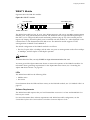
Summit Switch
Summit Switch Overview
Summit Switch Models
59
Summary of Features
Summit “i” series switches
Summit 200 Series
60
60
61
Memory Requirements
62
Port Connections
62
Following Safety Information
63
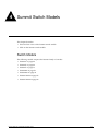
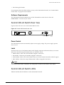
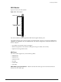
Summit Switch Models
Switch Models
65
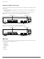
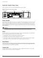
Summit1i Switch Front View
GBIC Ports
LEDs
66
66
67
Summit1i Switch Rear View
Power Sockets
Label
68
68
68
Extreme Networks Consolidated Hardware Guide
Reset Button
Console Port
68
68
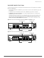
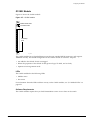
Summit5i Switch Front View
GBIC Ports
LEDs
69
70
71
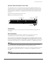
Summit5i Switch Rear View
Power Sockets
Label
Reset Button
Console Port
Management Port
71
71
72
72
72
72
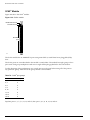
Summit7i Switch Front View
GBIC Ports
LEDs
Reset Button
Console Port
Modem Port
Management Port
PCMCIA Slot
73
74
75
75
75
76
76
76
Summit7i Switch Rear View
Power Sockets
Label
76
76
77
Summit1i, Summit5i, Summit7i, and Summit48i Switch LEDs
77
Summit48i Switch Front View
GBIC Ports
LEDs
78
78
79
Summit48i Switch Rear View
Power Sockets
Label
Reset Button
Console Port
80
80
80
80
80
Summit48si Switch Front View
Mini-GBIC Ports
Console Port
LEDs
81
81
82
82
Summit48si Switch Rear View
Power Supplies
Reset Button
82
82
83
Summit48si Power Supply LEDs
83
Summit48si Switch Bottom View
Labels
84
84
Summit48si Switch LEDs
85
Extreme Networks Consolidated Hardware Guide
5
Chapter 5
Part 4
Chapter 6
6
Summit 200-24 Switch Front View
Console Port
Port Connections
LEDs
Software Requirements
85
86
86
86
87
Summit 200-24 Switch Rear View
Power Socket
Label
87
87
87
Summit 200-24 Switch LEDs
87
Summit 200-48 Switch Front View
Console Port
Port Connections
LEDs
Software Requirements
89
89
89
90
90
Summit 200-48 Switch Rear View
Power Socket
Label
90
90
90
Summit 200-48 Switch LEDs
91
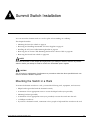
Summit Switch Installation
Mounting the Switch in a Rack
Placing the Switch on a Table or Shelf
Verifying a Successful Installation
93
97
97
Removing and Installing Summit48si AC Power Supplies
97
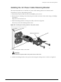
Installing the AC Power Cable Retaining Bracket
99
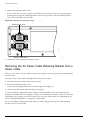
Removing the AC Power Cable Retaining Bracket from a Power Cable
100
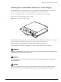
Installing the Summit48si Switch DC Power Supply
101
Preparing and Attaching the DC Power Supply Cabling
Attaching the Connector to the DC Power Supply
103
104
Removing the Switch from a Rack
104
Alpine Switch
Alpine 3800 Series Switch Overview
Summary of Features
Port Connections
109
110
Switch Components
Alpine 3808 Switch
Alpine 3804 Switch
111
111
111
Extreme Networks Consolidated Hardware Guide
Alpine 3802 Switch
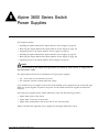
Power Supply
Following Safety Information
Chapter 7
Chapter 8
112
Alpine 3800 Series Switch Chassis
Alpine 3800 Series Architecture
Alpine 3808 Switch Front View
Alpine 3808 Switch Rear View
Alpine 3804 Switch Front View
Alpine 3804 Switch Rear View
Alpine 3802 Switch Front View
Alpine 3802 Switch Rear View
115
115
117
117
119
119
122
Installing the Chassis
Rack Installation
Grounding the Alpine 3800 Series Chassis
124
125
127
Removing the Chassis
128
Alpine 3800 Series Switch
Power Supplies
Power Supply LEDs
Chapter 9
112
112
130
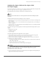
Installing the Alpine 3808 and the Alpine 3804
AC Power Supply
Verifying a Successful Installation
131
133
Removing the Alpine 3808 and the Alpine 3804
AC Power Supply
133
Supplying Power to the Alpine 3802 AC Power Supply
Verifying a Successful Installation
134
135
Installing the Alpine 3808 and the Alpine 3804
DC Power Supply
Selecting the Cabling
Installing the Power Supply
Attaching the Cabling and Supplying Power
Verifying a Successful Installation
135
136
136
139
140
Removing the Alpine 3808 and the Alpine 3804
DC Power Supply
140
Supplying Power to the Alpine 3802 DC Power Supply
Selecting the Cabling
Attaching the Cabling and Supplying Power
Verifying a Successful Installation
141
142
142
143
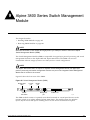
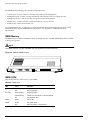
Alpine 3800 Series Switch Management Module
SMMi Memory
SMMi LEDs
Extreme Networks Consolidated Hardware Guide
146
146
7
Chapter 10
Chapter 11
Part 5
Chapter 12
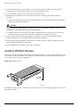
Installing SMMi Modules
Verifying the SMMi Module Installation
147
148
Removing SMMi Modules
148
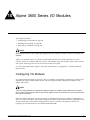
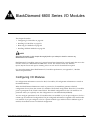
Alpine 3800 Series I/O Modules
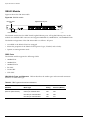
Configuring I/O Modules
GM-4Ti Module
GM-4Xi Module
GM-4Si Module
GM-WDMi Module
GM-16X3 Module
GM-16T3 Module
FM-24Ti Module
FM-24SFi Module
FM-24MFi Module
FM-32Ti Module
FM-32Pi Module
FM-8Vi Module
WM-4T1i Module
WM-4E1i Module
WM-1T3i Module
I/O Module LEDs
151
153
154
157
158
160
162
164
166
168
170
171
173
175
176
177
177
Installing I/O Modules
180
Verifying the I/O Module Installation
LED Indicators
Displaying Slot Status Information
181
181
181
Removing I/O Modules
182
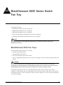
Alpine 3800 Series Switch Fan Tray
Alpine 3808 Fan Tray
183
Alpine 3804 Fan Tray
184
Alpine 3802 Fan Tray
184
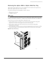
Removing the Alpine 3808 or Alpine 3804 Fan Tray
185
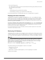
Installing the Alpine 3808 or Alpine 3804 Fan Tray
186
BlackDiamond Switch
BlackDiamond 6800 Series Switch Overview
Summary of Features
Port Connections
8
191
192
Extreme Networks Consolidated Hardware Guide
Chapter 13
Chapter 14
Switch Components
BlackDiamond 6816 Switch
BlackDiamond 6808 Switch
BlackDiamond 6804 Switch
BlackDiamond Power Supplies
Switch Connectivity and the Backplane
Packet Switching and Routing
193
193
194
194
194
194
195
Following Safety Information
195
BlackDiamond 6800 Series Switch Chassis
BlackDiamond 6800 Series Architecture
BlackDiamond 6816 Switch Front View
BlackDiamond 6816 Switch Rear View
BlackDiamond 6808 Switch Front View
BlackDiamond 6808 Switch Rear View
BlackDiamond 6804 Switch Front View
BlackDiamond 6804 Switch Rear View
197
197
199
200
202
203
205
Installing the Chassis
Rack Installation
Grounding the BlackDiamond 6800 Series Chassis
205
206
210
Removing the Chassis
210
BlackDiamond 6800 Series Switch Power Supplies
220 VAC Power Supplies
110 VAC Power Supplies
DC Power Supplies
Chapter 15
214
215
216
Installing a BlackDiamond 6800 Series Power Supply
AC Power Cable and Plug
Selecting the DC Cabling
Preparing the DC Cabling
Attaching the DC Cabling
Verifying a Successful Installation
217
221
221
222
222
223
Removing a BlackDiamond 6800 Series Power Supply
223
BlackDiamond 6800 Series Management Switch Module
MSM Activity
MSM Memory
MSM LEDs
229
230
231
Installing MSMs
Verifying the MSM Module Installation
231
234
Removing MSMs
235
Extreme Networks Consolidated Hardware Guide
9
Chapter 16
Chapter 17
Part 6
Chapter 18
Part 7
10
BlackDiamond 6800 Series I/O Modules
Configuring I/O Modules
G8Ti Module
G8Xi Module
G12SXi Module
G16X3 Module
G24T3 Module
WDMi Module
10GLRi Module
F48Ti Module
F96Ti Module
F32Fi Module
P3cSi, P3cMi, P12cSi, and P12cMi Modules
ARM
MPLS Module
A3cSi and A3cMi Modules
I/O Module LEDs
237
238
239
241
242
245
247
249
252
253
257
258
262
265
268
272
Installing I/O Modules
273
Verifying the I/O Module Installation
LED Indicators
Displaying Slot Status Information
274
274
275
Removing I/O Modules
275
Installing XENPAK Modules
276
BlackDiamond 6800 Series Switch
Fan Tray
BlackDiamond 6816 Fan Trays
279
BlackDiamond 6808 Fan Tray
280
BlackDiamond 6804 Fan Tray
281
Removing a BlackDiamond 6800 Series Fan Tray
282
Installing a BlackDiamond 6800 Series Fan Tray
284
Switch Operation
Initial Switch and Management Access
Connecting Equipment to the Console Port
289
Logging In for the First Time
291
Appendixes
Extreme Networks Consolidated Hardware Guide
Appendix A
Safety Information
Important Safety Information
Power
Power Cable
Fuse
Connections
Lithium Battery
Appendix B
Switch Technical Specifications
Appendix C
Module Technical Specifications
295
295
296
296
297
297
Alpine Modules
310
BlackDiamond Modules
319
Common Module Specifications
331
Index
Extreme Networks Consolidated Hardware Guide
11
12
Extreme Networks Consolidated Hardware Guide
Preface
This preface provides an overview of this guide, describes guide conventions, and lists other
publications that might be useful.
NOTE
To ensure proper operation of your Extreme Networks equipment, read this guide before you install any
Extreme Networks equipment.
Introduction
This guide provides the required information to install an Extreme Networks® Summit™ switch, Alpine®
switch, or BlackDiamond® switch. It also contains information about site location, switch functionality,
and switch operation.
This guide is intended for use by network administrators who are responsible for installing and setting
up network equipment. It assumes a basic working knowledge of:
• Local Area Networks (LANs)
• Ethernet concepts
• Ethernet switching and bridging concepts
• Routing concepts
• Simple Network Management Protocol (SNMP)
See the ExtremeWare Software User Guide for information about configuring an Extreme Networks switch.
NOTE
If the information in the Release Notes that shipped with your switch differs from the information in this
guide, follow the Release Notes.
Extreme Networks Consolidated Hardware Guide
13
Preface
Conventions
Table 1 and Table 2 list conventions used throughout this guide.
Table 1: Notice icons
Icon
Notice Type
Alerts you to...
Note
Important features or instructions.
Caution
Risk of personal injury, system damage,
or loss of data.
Warning
Risk of severe personal injury.
Table 2: Text conventions
Convention
Description
Screen displays
This typeface represents information as it appears on the screen,
or command syntax.
Screen displays bold
This typeface represents commands that you type.
The words “enter”
and “type”
When you see the word “enter” in this guide, you must type
something, and then press the Return or Enter key. Do not press
the Return or Enter key when an instruction simply says “type.”
[Key] names
Key names appear in text in one of two ways:
•
Referenced by their labels, such as “the Return key” or “the
Escape key”
•
Written with brackets, such as [Return] or [Esc]
If you must press two or more keys simultaneously, the key names
are linked with a plus sign (+). Example:
Press [Ctrl]+[Alt]+[Del].
Words in italicized type
Italics emphasize a point of information or denote new terms at the
place where they are defined in the text.
Related Publications
The Extreme Networks switch documentation set includes:
• Extreme Networks Consolidated Hardware Guide (this guide)
• ExtremeWare Software User Guide
• ExtremeWare Software Command Reference Guide
• ExtremeWare Release Notes
14
Extreme Networks Consolidated Hardware Guide
About This Guide
Documentation for Extreme Networks products is available from the Extreme Networks website at the
following location:
http://www.extremenetworks.com/services/documentation/
You can select and download the following Extreme Networks documentation from the Documentation
section of the Services page:
• Release Notes (you must have a valid service contract to access the release notes)
• Software User Guides
• Hardware User Guides
• White Papers
• Troubleshooting Tools
• Preventative Maintenance
• Instructional Videos
• Archives
About This Guide
This guide describes how to prepare your site and how to install, maintain, and operate your Extreme
Networks switch. It contains information on features that are common to all switches, as well as
switch-specific features. This guide contains seven parts:
• Common Features—Describes features that are shared by the Extreme Networks family of switches.
This section describes software images, full-duplex support, management ports, mini-GBIC and
GBIC modules and their installation.
• Site Planning—Describes how to evaluate, plan, and determine the location of your Extreme
Networks switch.
• Summit Switch—Describes the features that are specific to the Summit switch. This section provides
an overview of the Summit switch, information about model types, summary of features, and
installation guidelines.
• Alpine Switch—Describes the features that are specific to the Alpine switch. This section provides an
overview of the Alpine switch, information about model types, a summary of features, and
installation guidelines.
• BlackDiamond Switch—Describes the features that are specific to the BlackDiamond switch. This
section provides an overview of the BlackDiamond switch, information about model types, a
summary of features, and installation guidelines.
• Switch Operation—Describes how to power on any Extreme Networks switch, verify the switch
installation, connect equipment to the console port, and log in to the switch for the first time.
• Appendixes—Includes information about safety requirements and technical specifications.
How To Use This Guide
Each chapter of this guide contains information on how to successfully operate your Extreme Networks
switch. The Summit-, Alpine-, and BlackDiamond-specific chapters contain information that is
applicable to that family of switch only. All other chapters are applicable to any Extreme Networks
switch.
Extreme Networks Consolidated Hardware Guide
15
Preface
Switch-Specific Information
For switch-specific information, be sure to read the applicable switch-specific chapter. For example, if
you have a BlackDiamond switch and you need to remove and replace an I/O module, see “Removing
I/O Modules” in Chapter 16 for details about how to remove and replace an I/O module in a
BlackDiamond chassis.
Common Information
For items applicable to any Extreme Networks switch, make sure you read the appropriate chapter. For
example, to learn how to prepare your site for installing your Extreme Networks equipment, see
Chapter 2, “Site Preparation.”
This guide also contains appendices that describe:
• Switch safety issues
• Switch specifications
• Module specifications
Appendix A, “Safety Information” describes important safety issues such as power, power cables, and
fuses.
Appendix B, “Switch Technical Specifications” is organized according to the family of switch: Summit,
Alpine, and BlackDiamond. This appendix describes switch specifications such as physical dimensions,
weight, certifications, and power supply parameters.
Information that is common to all switches is described at the end of the appendix.
Appendix C, “Module Technical Specifications” is organized according to the family of switch and
modules available for that switch, and describes module specifications such as physical dimensions,
weight, and standards.
Information that is common to all modules is described at the end of the appendix.
16
Extreme Networks Consolidated Hardware Guide
Part 1
Common Features
1
Summary of Common Switch Features
This chapter describes the features that are shared in common by the Extreme Networks family of
switches. The following topics are described in greater detail:
• Software Images on page 19
• Full-Duplex Support on page 20
• Management Ports on page 20
• Mini-GBIC Type and Hardware/Software Support on page 20
• GBIC Type and Hardware/Software Support on page 24
Software Images
When you receive a new Extreme Networks switch, be aware that an the ExtremeWare® software image
and a BootROM image has been preinstalled at the factory. To verify the software image you are
running on your switch, use the show version command. The show version command displays the
hardware and software versions currently running on the switch. To ensure that you have the latest
software and BootROM image, go to the support login portion of the Tech Support page at:
http://www.extremenetworks.com/services/
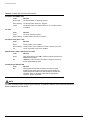
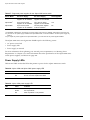
If your switch is running ExtremeWare version 6.2 or later, the Power LED activity is different from
previous versions of ExtremeWare. All other LED activity is the same. See Table 3 for more information
about the Power LED activity on switches running ExtremeWare version 6.2 or later.
Table 3: Power LED activity for switches running ExtremeWare version 6.2 or later
LED
Color
Indicates
Power LED
Green
The indicated power supply unit (PSU) is powered up.
Amber
A PSU is installed, but not connected to power.
Off
The PSU is not receiving power or no PSU is present.
NOTE
If the information in the Release Notes that shipped with your switch differs from the information in this
guide, follow the Release Notes.
Extreme Networks Consolidated Hardware Guide
19
Summary of Common Switch Features
Full-Duplex Support
Extreme Networks switches provide full-duplex support for all ports. This means that frames can be
transmitted and received simultaneously, which, in effect, doubles the bandwidth that is available on a
link. Most ports on an Extreme Networks switch autonegotiate for half-duplex or full-duplex operation.
Gigabit Ethernet and 100BASE-FX ports operate in full-duplex mode only in accordance with technical
standards.
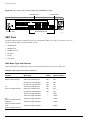
Management Ports
The 10/100BASE-TX Ethernet management port allows you to communicate directly to the CPU of the
switch. You can plug an Ethernet cable directly from your laptop into the management port. This
provides you with direct access into the switch and allows you to view and locally manage the switch
configurations.
Do not assign an in-band IP address to the management port VLAN. The management port VLAN is an
out-of-band VLAN, so if it is assigned an in-band IP address (an address where the source and
destination are in the same subnet), the switch will treat it as a normal VLAN and attempt to route
traffic through it.
The management port is located on the following Extreme Networks devices:
• Summit5i—The management port is located on the back side of the switch
• Summit7i—The management port is located on the front side of the switch
• Alpine—Switch Management Module (SMMi) for the Alpine series switch
• BlackDiamond—Management Switch Fabric Module (MSM64i) for the BlackDiamond series switch
Extreme Networks does not recommend that you use the management port to route traffic to any front
panel port on the switch. The management port is designed for switch management purposes.
Mini-GBIC Type and Hardware/Software Support
The Summit48si and Summit series switches, the BlackDiamond G16X3 module, and the Alpine
GM-16X3 module support the small form pluggable (SFP) GBIC, also known as the mini-GBIC. The
switches and the modules identify the type of mini-GBIC that is installed and verifies that the
mini-GBIC is an Extreme Networks-certified mini-GBIC.
Mini-GBIC Types and Specifications
There are three types of mini-GBIC interfaces:
• SX mini-GBIC, which conforms to the 1000BASE-SX standard
• LX mini-GBIC, which conforms to the 1000BASE-LX standard
• ZX mini-GBIC, which conforms to the IEEE 802.3z standard
Use only Extreme Networks-certified mini-GBICs, available from Extreme Networks, into the
mini-GBIC port in the switch or module.
20
Extreme Networks Consolidated Hardware Guide
Mini-GBIC Type and Hardware/Software Support
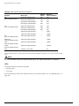
Table 4 describes the specifications for the SX mini-GBIC interface, Table 5 describes the specifications
for the LX mini-GBIC interface, and Table 6 describes the specifications for the ZX mini-GBIC interface.
Table 4: SX mini-GBIC specifications
Parameter
Minimum
Typical
Maximum
Transceiver
Optical output power
-9.5 dBm
Center wavelength
830 nm
-4 dBm
850 nm
860 nm
Receiver
Optical input power sensitivity
-21 dBm
Optical input power maximum
Operating wavelength
-4 dBm
830 nm
860 nm
General
Total system budget
11.5 dB
Total optical system budget for the SX mini-GBIC is 11.5 dB. Extreme Networks recommends that 3 dB
of the total budget be reserved for losses induced by cable splices/connectors and operating margin.
While 8.5 dB remains available for cable induced attenuation, the 1000BASE-SX standard specifies
supported distances of 275 meters over 62.5 micron multimode fiber and 550 meters over 50 micron
multimode fiber. There is no minimum attenuation or minimum cable length restriction.
Table 5: LX mini-GBIC specifications
Parameter
Minimum
Typical
Maximum
Transceiver
Optical output power
-9.5 dBm
Center wavelength
1275 nm
-3 dBm
1310 nm
1355 nm
Receiver
Optical input power sensitivity
-23 dBm
Optical input power maximum
Operating wavelength
-3 dBm
1270 nm
1355 nm
General
Total system budget
13.5 dB
Total optical system budget for the LX mini-GBIC is 13.5 dB. Measure cable plant losses with a 1310 nm
light source and verify this to be within budget. When calculating the maximum distance attainable
using optical cable with a specified loss per kilometer (for example 0.25 dB/km) Extreme Networks
recommends that 3 dBm of the total budget be reserved for losses induced by cable splices/connectors
and operating margin. Thus, 10.5 dB remains available for cable induced attenuation. There is no
minimum system budget or minimum cable length restriction because the maximum receive power is
the same as the maximum transmit power. There is no minimum attenuation or minimum cable length
restriction.
Extreme Networks Consolidated Hardware Guide
21
Summary of Common Switch Features
Table 6: ZX mini-GBIC specifications
Parameter
Minimum
Typical
Maximum
Optical output power
-2 dBm
0 dBm
3 dBm
Center wavelength
1540 nm
1550 nm
1570 nm
Transceiver
Receiver
Optical input power sensitivity
-23 dBm
Optical input power maximum
Operating wavelength
-3 dBm
1540 nm
1550 nm
1570 nm
The ZX mini-GBIC is compatible with and interoperates with long range GBICs. For more information
about the budget requirements and minimum attenutation requirements of long range GBICs, see “Long
Range GBIC System Budgets” on page 28.
Safety Information
Before you begin the process of installing or replacing a mini-GBIC, read the safety information in this
section.
CAUTION
Mini-GBICs can emit invisible laser radiation. Avoid direct eye exposure to beam.
Mini-GBICs are class 1 laser devices, and they operate at 3.3 V. Use only Extreme Networks-certified
mini-GBIC devices.
If you see an amber blinking mini-GBIC port status LED after you install a mini-GBIC into the
Summit48si or Summit 200 series switch, BlackDiamond G16X3 module, or an Alpine GM-16X3 module,
this means the mini-GBIC is not certified by Extreme Networks. To correct this problem, install an
Extreme Networks-certified mini-GBIC, available from Extreme Networks, mini-GBIC port.
If you install a mini-GBIC not certified by Extreme Networks into an Alpine GM-16X3 module and
insert a cable to bring up the link, the port status LED remains “off” and an error specifying the use of a
non-Extreme Networks-certified mini-GBIC is sent to the syslog. To view the syslog and to determine
why the link is down, use the show log command. To correct this problem, install an Extreme
Networks-certified mini-GBIC, available from Extreme Networks, into the mini-GBIC slot in the
module.
Preparing to Install or Replace a Mini-GBIC
To ensure proper installation, complete the following five tasks before inserting the mini-GBIC:
1 Disable the port that is needed to install or replace the mini-GBIC.
2 Inspect and clean the fiber tips, coupler, and connectors.
3 Prepare and clean an external attenuator, if needed.
4 Do not stretch the fiber.
22
Extreme Networks Consolidated Hardware Guide
Mini-GBIC Type and Hardware/Software Support
5 Make sure the bend radius of the fiber is not less than 2 inches (5.08 cm).
In addition to the previously described tasks, Extreme Networks recommends the following when
installing or replacing mini-GBICs on an active network:
• Use the same type of mini-GBIC at each end of the link.
• Connect one end of the link to the Tx port. Without an attenuator, measure the total loss from the Tx
port to the other site of the link. The total loss must not exceed the total optical system budget.
After you complete these described tasks, you are ready to install or replace a mini-GBIC.
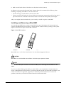
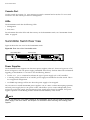
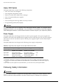
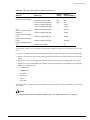
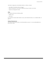
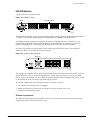
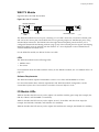
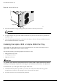
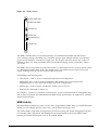
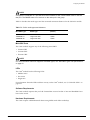
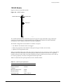
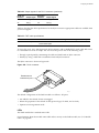
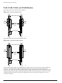
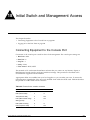
Installing and Removing a Mini-GBIC
You can add mini-GBICs into, or remove mini-GBICs from your Summit48si and Summit 200 series
switches, BlackDiamond G16X3 module, or Alpine GM-16X3 module without powering off the system.
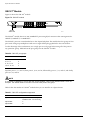
Figure 1 shows the two types of mini-GBIC connectors.
Figure 1: Mini-GBIC modules
Module A
Module B
XM_024
Mini-GBICs are a 3.3 V Class 1 laser devices. Use only Extreme-approved devices.
CAUTION
Mini-GBICs can emit invisible laser radiation. Avoid direct eye exposure to beam.
NOTE
Remove the LC fiber-optic connector from the mini-GBIC prior to removing the mini-GBIC from the
switch.
If you see an amber blinking mini-GBIC port status LED on your Summit48si or Summit 200 series
switch, a BlackDiamond G16X3 module, or an Alpine GM-16X3 module, the mini-GBIC installed in your
switch or module is not approved, supported, or certified by Extreme Networks. To correct this
problem, ensure that you install an Extreme Networks-certified mini-GBIC.
Extreme Networks Consolidated Hardware Guide
23
Summary of Common Switch Features
To remove a mini-GBIC similar to the one labeled “Module A” in Figure 1, gently depress and hold the
black plastic tab at the bottom of the connector to release the mini-GBIC, and pull the mini-GBIC out of
the SFP receptacle.
To remove a mini-GBIC connector similar to the one labeled “Module B” in Figure 1, gently rotate the
front handle and pull the mini-GBIC out of the SFP receptacle.
To insert a mini-GBIC connector:
NOTE
Mini-GBICs can be installed in the SFP mini-GBIC receptacles only.
1 Holding the mini-GBIC by its sides, insert the mini-GBIC into the SFP receptacle on the switch or
module.
2 Slide the mini-GBIC into the SFP receptacle until you hear an audible click, indicating the mini-GBIC
is securely seated into the SFP receptacle. If the mini-GBIC has a handle, push up on the handle to
secure the mini-GBIC.
GBIC Type and Hardware/Software Support
Most Extreme Networks switches support two types of GBICs: the Parallel ID GBIC and the Serial ID
GBIC. The switch can identify the media type for the GBIC that is installed. Initial ExtremeWare
software versions do not support Serial ID GBICs. If Serial ID GBICs are installed in a switch with an
initial software release, the switch will not bring up the link on GBIC ports.
GBIC Media Types and Distances
Table 7 describes the media types and associated maximum distances for each GBIC type.
Table 7: GBIC types and maximum distances
Standard
Media Type
Mhz•Km
Rating
Maximum
Distance (Meters)
SX
(850 nm optical window)
50/125 µm multimode fiber
400
500
50/125 µm multimode fiber
500
550
62.5/125 µm multimode fiber
160
220
62.5/125 µm multimode fiber
200
275
50/125 µm multimode fiber
400
550
50/125 µm multimode fiber
500
550
62.5/125 µm multimode fiber
500
550
10/125 µm single-mode fiber
–
5,000
10/125 µm single-mode fiber*
–
10,000
ZX
(1550 nm optical window)
10/125 µm single-mode fiber
–
50,000
ZX Rev 03
(1550 nm optical window)
10/125 µm single-mode fiber
LX
(1310 nm optical window)
24
70,000
Extreme Networks Consolidated Hardware Guide
GBIC Type and Hardware/Software Support
Table 7: GBIC types and maximum distances (continued)
Mhz•Km
Rating
Standard
Media Type
LX70
(1550 nm optical window)
10/125 µm single-mode fiber
LX100
(1550 nm optical window)
10/125 µm single-mode fiber
UTP
Category 5 UTP cable
–
Maximum
Distance (Meters)
70,000
100,000
–
80
*Extreme Networks proprietary. Connections between two Extreme Networks 1000BASE-LX interfaces can use a maximum distance of 10,000
meters.
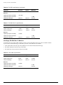
GBIC Specifications
Table 8 through Table 14 describe the specifications for each GBIC type.
Table 8: 1000BASE-SX specifications
Parameter
Minimum
Typical
Maximum
Transceiver
Optical output power
-9.5 dBm
Center wavelength
830 nm
-4 dBm
850 nm
860 nm
Receiver
Optical input power sensitivity
-17 dBm
Optical input power maximum
Operating wavelength
0 dBm
830 nm
860 nm
Table 9: 100BASE-LX specifications
Parameter
Minimum
Typical
Maximum
Transceiver
Optical output power
-11 dBm
Center wavelength
1270 nm
-3 dBm
1310 nm
1355 nm
Receiver
Optical input power sensitivity
-19 dBm
Optical input power maximum
Operating wavelength
-3 dBm
1270 nm
1355 nm
Table 10: ZX GBIC specifications
Parameter
Minimum
Typical
Maximum
-4 dBm
-3 dBm
-1 dBm
Transceiver
Optical output power
Extreme Networks Consolidated Hardware Guide
25
Summary of Common Switch Features
Table 10: ZX GBIC specifications (continued)
Parameter
Minimum
Typical
Maximum
Center wavelength
1540 nm
1550 nm
1570 nm
Receiver
Optical input power sensitivity
-23.5 dBm
Optical input power maximum
Operating wavelength
-1 dBm
1540 nm
1550 nm
1570 nm
Table 11: ZX GBIC Rev 03 specifications
Parameter
Minimum
Typical
Maximum
Optical output power
-2 dBm
0 dBm
2 dBm
Center wavelength
1540 nm
1550 nm
1570 nm
Transceiver
Receiver
Optical input power sensitivity
-23 dBm
Optical input power maximum
Operating wavelength
-1 dBm
1540 nm
1550 nm
1570 nm
Identifying ZX GBIC Rev 03 Modules
To identify the type of ZX GBIC module you have, look at the label on the top of the ZX GBIC module.
If you see one of the following on the label, you have a ZX GBIC Rev 03 module:
• DVA-1203 sticker near the top of the label that covers the Extreme Networks logo
• ZX GBIC (1203) text near the top of the label
• ZX GBIC Rev 03 text near the center of the label
Table 12: LX70 GBIC specifications
Parameter
Minimum
Typical
Maximum
Optical output power
0 dBm
3 dBm
5.2 dBm
Center wavelength
1540 nm
1550 nm
1570 nm
Transceiver
Receiver
Optical input power sensitivity
-22 dBm
Optical input power maximum
Operating wavelength
26
-3 dBm
1270 nm
1570 nm
Extreme Networks Consolidated Hardware Guide
GBIC Type and Hardware/Software Support
Table 13: LX100 GBIC specifications
Parameter
Minimum
Typical
Maximum
Optical output power
1 dBm
3 dBm
5 dBm
Center wavelength
1546 nm
1551 nm
1557 nm
Transceiver
Receiver
Optical input power sensitivity
-29 dBm
Optical input power maximum
Operating wavelength
-7 dBm
1546 nm
1551 nm
1557 nm
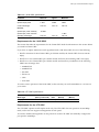
Requirements for the LX100 GBIC
This section describes the requirements for the LX100 GBIC. Read the information in this section before
you install an LX100 GBIC.
If you have an Alpine 3800 series switch populated with a GM-4Xi module, do one of the following:
• Install a maximum of three LX100 GBICs per GM-4Xi module; the fourth GBIC slot must remain
empty
• Install two or less LX100 GBICs per GM-4Xi module and leave the remaining GBIC slots empty
• Install two or less LX100 GBICs per GM-4Xi module and install any combination of the following
GBICs into the empty slots:
— 1000BASE-SX
— 1000BASE-LX
— ZX GBIC
— ZX Rev 03
— LX70
— UTP GBIC
To ensure correct operation of the LX100 GBIC, make sure that you run ExtremeWare 6.1.9 or later on
your switch.
Table 14: UTP GBIC specifications
Media Type
Bit Error Rate
(Errors per Second)
Category 5 UTP cable
10-12
Data
Rate
1 Gbps
Min Distance
(Meters)
Max Distance
(Meters)
2
80
Requirements for the UTP GBIC
The UTP GBIC operates in full-duplex mode only. The UTP GBIC does not operate in 10/100 Mbps
mode, and it does not support autonegotiation of link speed.
You need to disable autonegotiation on the ports that use the UTP GBIC and manually configure the
port speed to 1000 Mbps.
Extreme Networks Consolidated Hardware Guide
27
Summary of Common Switch Features
The following example disables autonegotiation, configures a port speed of 1000 Mbps, and specifies
full-duplex mode for port 4 on a stand-alone switch:
config ports 4 auto off speed 1000 duplex full
The following example disables autonegotiation, configures a port speed of 1000 Mbps, and specifies
full-duplex mode for port 1 on a G8Xi module located in slot 1 of a modular switch:
config ports 1:1 auto off speed 1000 duplex full
The UTP GBIC is supported on “i” series products only.
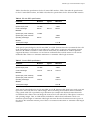
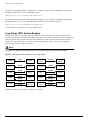
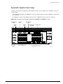
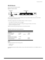
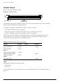
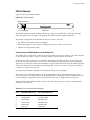
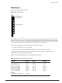
Long Range GBIC System Budgets
Measure cable plant losses with a 1550 nm light source and verify this to be within budget. When
calculating the maximum distance attainable, using optical cable with a specified loss per kilometer (for
example, 0.25 db/km), Extreme Networks recommends that 3 dB of the total budget be reserved for
losses induced by cable splices, connectors, and operating margin. Figure 2 shows the total optical
system budget between long range GBICs.
NOTE
The fiber loss budget plus all other penalties must not exceed the total optical system budget.
Figure 2: Total optical system budgets for long range GBICs
ZX GBIC
LX70
19.5 dB
22.0 dB
23.0 dB
LX70
20.0 dB
ZX GBIC
ZX GBIC
Rev. 03
LX70
LX100
ZX GBIC
Rev. 03
LX70
23.5 dB
LX70
ZX GBIC
19.0 dB
ZX GBIC
ZX GBIC
Rev. 03
ZX GBIC
Rev. 03
21.5 dB
30.0 dB
ZX GBIC
Rev. 03
LX100
29.0 dB
18.0 dB
ZX GBIC
21.0 dB
23.0 dB
LX100
25.0 dB
24.5 dB
LX100
27.0 dB
24.0 dB
LX100
XM_041
The ZX mini-GBIC is equivalent to the ZX Rev 03 GBIC.
28
Extreme Networks Consolidated Hardware Guide
GBIC Type and Hardware/Software Support
Table 15 lists the minimum attenuations that are required by each long range GBIC to prevent saturation
of the receiver.
Table 15: Minimum attenuation requirements
Receivers
Transceivers
GBIC Type
LX70
ZX (prior to
Rev 03)
ZX Rev 03
LX100
LX70
10 dB
10 dB
10 dB
11 dB
ZX (prior to
Rev 03)
0 dB
0 dB
0 dB
8 dB
ZX Rev 03
8 dB
8 dB
8 dB
9 dB
LX100
11 dB
11 dB
11 dB
12 dB
The ZX mini-GBIC is equivalent to the ZX Rev 03 GBIC.
Safety Information
Before you install or replace a GBIC, read the safety information in this section.
CAUTION
GBICs can emit invisible laser radiation. Avoid direct eye exposure to beam.
GBICs are class 1 laser devices, and they operate at 5 V. Use only Extreme-approved devices.
Remove the SC fiber-optic or the RJ-45 connector from the GBIC prior to removing the GBIC from the
I/O module or the switch.
Preparing to Install or Replace a GBIC
This section describes the preparation steps that you must perform before inserting and securing a
GBIC.
CAUTION
GBICs can emit invisible laser radiation. Avoid direct eye exposure to beam.
To ensure proper installation, complete the following five tasks before inserting the GBIC:
1 Inspect and clean the fiber tips, coupler, and connectors.
2 Prepare and clean an external attenuator, if needed.
3 Calculate the link budget.
4 Do not stretch the fiber.
5 Make sure the bend radius of the fiber is not less than 2 inches.
Extreme Networks Consolidated Hardware Guide
29
Summary of Common Switch Features
In addition to the previously described tasks, Extreme Networks recommends the following when
installing or replacing GBICs on an active network:
• Use the same type of GBIC at each end of the link.
• Connect one end of the link to the Tx port. Without an attenuator, measure the total loss from the Tx
port to the other site of the link. The total loss must not exceed the total optical system budget listed
in Figure 2.
• Use dispersion shifted fiber whenever possible. This provides superior performance in the 1550 nm
range.
After you complete all of these described tasks, you are ready to install or replace a GBIC.
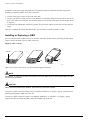
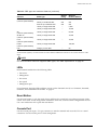
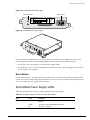
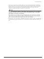
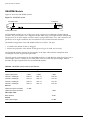
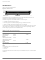
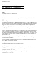
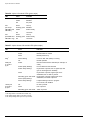
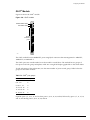
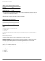
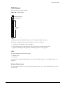
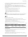
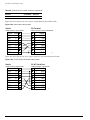
Installing or Replacing a GBIC
You can add and remove GBICs from your Extreme Networks switch without powering off the system.
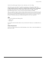
Figure 3 shows the three types of GBIC connectors.
Figure 3: GBIC modules
Handle
Tab
Tab
Module A
Module B
Module C
EW_GBIC
GBICs are a Class 1 laser device. Use only Extreme-approved devices.
NOTE
Remove the SC fiber-optic or the RJ-45 connector from the GBIC prior to removing the GBIC from the
I/O module or the switch.
CAUTION
GBICs can emit invisible laser radiation. Avoid direct eye exposure to beam.
To remove a GBIC connector similar to the one labeled “Module A” in Figure 3, gently rotate the front
handle up and pull the GBIC out of the slot.
To remove a GBIC connector similar to one labeled “Module B” or “Module C” in Figure 3, gently
squeeze the sides to release the GBIC, and pull the GBIC out of the slot.
30
Extreme Networks Consolidated Hardware Guide
GBIC Type and Hardware/Software Support
To insert a GBIC connector:
1 Holding the GBIC by its sides, insert the GBIC into the slot on the I/O module or the switch.
2 Slide the GBIC into the slot until you hear an audible click, indicating the GBIC is securely seated. If
the GBIC has a handle, push down on the handle to secure the GBIC.
Extreme Networks Consolidated Hardware Guide
31
Summary of Common Switch Features
32
Extreme Networks Consolidated Hardware Guide
Part 2
Site Planning
2
Site Preparation
This chapter describes how to prepare your site for installing Extreme Networks equipment. It contains
information on environmental and cabling requirements, power requirements, and building and
electrical code organizations.
This chapter includes these sections:
• Planning Your Site on page 36
• Meeting Site Requirements on page 36
• Evaluating and Meeting Cable Requirements on page 47
• Meeting Power Requirements on page 52
• Applicable Industry Standards on page 55
The requirements described in this chapter are intended for the system administrator, network
equipment technician, or network manager who is responsible for installing and managing the network
hardware. It assumes a working knowledge of local area network (LAN) operations, and a familiarity
with communications protocols that are used on interconnected LANs. Installation, maintenance, and
removal of a switch, chassis, or its components must be done by qualified service personnel only.
Qualified service personnel have had appropriate technical training and experience that is necessary to
be aware of the hazards to which they are exposed when performing a task and of measures to
minimize the danger to themselves or other people.
By carefully planning your site, you can maximize the performance of your existing network and ensure
that it is ready to migrate to future networking technologies.
To learn more about safety issues and to ensure safety compliance, see Appendix A.
WARNING!
Read the safety information in Appendix A thoroughly before installing your Extreme Networks switch.
Failure to follow this safety information can lead to personal injury or damage to the equipment.
Extreme Networks Consolidated Hardware Guide
35
Site Preparation
Planning Your Site
To install your equipment successfully, you should plan your site carefully. The site planning process
has three major steps:
Step 1: Meeting Site Requirements
Your physical installation site must meet several requirements for a safe and successful installation:
• Building and electrical code requirements
• Environmental, safety, and thermal requirements for the equipment you plan to install
• Distribution rack requirements
Step 2: Evaluating and Meeting Cable Requirements
After examining your physical site and ensuring all environment requirements are met, you should
evaluate and compare your existing cable plant with the requirements of the Extreme Networks
equipment to determine if you need to install new cables (or cabling).
Step 3: Meeting Power Requirements
To run your equipment safely, you must meet the specific power requirements for the Extreme
Networks equipment that you plan to install.
NOTE
Review and follow the safety information before you install your equipment.
Meeting Site Requirements
This section addresses the various requirements to consider when preparing your installation site,
including:
• Operating Environment Requirements
• Rack Specifications and Recommendations
Operating Environment Requirements
You need to verify that your site meets all environmental and safety requirements.
Virtually all areas of the United States are regulated by building codes and standards. During the early
planning stages of installing or modifying your LAN, it is important that you develop a thorough
understanding of the regulations that pertain to your location and industry.
Building and Electrical Codes
Building and electrical codes vary depending on your location. Comply with all code specifications
when planning your site and installing cable. The following sections are provided as a resource to
obtain additional information.
36
Extreme Networks Consolidated Hardware Guide
Meeting Site Requirements
Three major building codes are:
• Uniform Building Code—produced by the International Conference of Building Officials (ICBO);
5360 South Workman Mill Road; Whittier, California 90601 USA. www.icbo.org
• BOCA Basic Building Code—produced by the Building Officials and Code Administrators (BOCA)
International, Inc.; 4051 West Flossmoor Road; Country Club Hills, Illinois 60478 USA.
www.bocai.org
• Standard Building Code (SBC)—produced by the Southern Building Code Congress International,
Inc.; 900 Montclair Road; Birmingham, Alabama 35213 USA. www.sbcci.org
Five authorities on electrical codes are:
• National Electrical Code (NEC) Classification (USA only)—a recognized authority on safe electrical
wiring. Federal, state, and local governments use NEC standards to establish their own laws,
ordinances, and codes on wiring specifications. The NEC classification is published by the National
Fire Protection Association (NFPA). The address is NFPA; 1 Batterymarch Park; Quincy,
Massachusetts 02269 USA. www.nfpa.org
• Underwriters’ Laboratory (UL) (USA only)—an independent research and testing laboratory. UL
evaluates the performance and capability of electrical wiring and equipment to determine whether
they meet certain safety standards when properly used. Acceptance is usually indicated by the
words “UL Approved” or “UL Listed.” The address is UL; 333 Pfingsten Road; Northbrook, Illinois
60062-2096 USA. www.ul.com
• National Electrical Manufacturing Association (NEMA) (USA only)—an organization of electrical
product manufacturers. Members develop consensus standards for cables, wiring, and electrical
components. The address is NEMA; 2101 L Street N.W.; Washington, D.C. 20037 USA.
www.nema.org
• Electronics Industry Association (EIA)—a trade association that develops technical standards,
disseminates marketing data, and maintains contact with government agencies in matters relating to
the electronics industry. The address is EIA; 2001 Eye Street N.W.; Washington, D.C. 20006 USA.
www.eia.org
• Federal Communications Commission (FCC)—a commission that regulates all interstate and foreign
electrical communication systems that originate in the United States according to the
Communications Act of 1934. The FCC regulates all U.S. telephone and cable systems. The address is
FCC; 1919 M Street N.W.; Washington, D.C. 20554 USA.
Wiring Closet Considerations
You should consider the following recommendations for your wiring closet:
• Ensure that your system is easily accessible for installation and service. See “Rack Specifications and
Recommendations” on page 45 for specific recommendations.
• Use appropriate AC power for your switch, as described in Table 16.
Table 16: AC power requirements
Switch Type
Country
Requirements
Alpine/Summit
North America
13 A service receptacle, NEMA 5-15 for 110/220 VAC power supplies.
Alpine/Summit
United Kingdom
10 A service receptacle, BS 1363 for 110/220 VAC power supplies.
Alpine/Summit
International
10 A service receptacle, CEE 7/7 for 110/220 VAC power supplies.
Alpine/Summit
Australia
10 A service receptacle, AS 3112 for 110/220 VAC power supplies.
Alpine/Summit
Japan
15 A service receptacle, JIS 8303 for 110/220 VAC power supplies.
Extreme Networks Consolidated Hardware Guide
37
Site Preparation
Table 16: AC power requirements (continued)
Switch Type
Country
Requirements
BlackDiamond
North America
20 A service receptacle, NEMA L6-20 (locking) for BlackDiamond 110
VAC power supplies.
BlackDiamond
North America
20 A service receptacle, NEMA L6-20 (locking) for BlackDiamond 220
VAC power supplies.
BlackDiamond
International
16 A/20 A service receptacle, IEC 60309 for BlackDiamond 220 VAC
power supplies.
BlackDiamond
North America
20 A service receptacle, NEMA 5-20 (non-locking) for BlackDiamond 110
VAC power supplies.
BlackDimamond North America
20 A service receptacle, NEMA 6-20 (non-locking) for BlackDiamond 220
VAC power supplies.
BlackDiamond
International
16 A service receptacle, CEE 7/7 for BlackDiamond 220 VAC power
supplies.
BlackDiamond
Australia
15 A service receptacle, 036 for BlackDiamond 220 VAC power supplies.
• Use appropriate DC power for your switch, as described in Table 17.
Table 17: DC power requirements
Switch Type
Country
Requirements
Alpine
International
•
Use 30 A at -40 VDC (or equivalent power between -40 and -70 VDC)
for Alpine DC power supplies.
•
For Alpine DC power and ground cables, use:
— 8 AWG, high strand-count copper wire cable (Alpine 3808)
— 10 AWG, high strand-count copper wire cable (Alpine 3804)
— 14 AWG, high strand-count copper wire cable (Alpine 3802)
BlackDiamond
International
•
Use 55 A service for BlackDiamond DC power supplies.
•
For BlackDiamond DC power cables, use 4 AWG, high strand-count
copper wire cable.
• Use a vinyl floor covering in your wiring closet. (Concrete floors accumulate dust, and carpets can
cause static electricity.)
• Prevent unauthorized access to wiring closets by providing door locks. Install the equipment in a
secured, enclosed, and restricted-access area, ensuring that only qualified service personnel have
access to the equipment.
• Provide adequate overhead lighting for easy maintenance.
• Ensure that each wiring closet has a suitable ground. All distribution racks and equipment installed
in the closet should be grounded.
• Ensure that all system environmental requirements are met, such as ambient temperature and
humidity.
NOTE
Extreme Networks recommends that you consult an electrical contractor for commercial building and
wiring specifications.
38
Extreme Networks Consolidated Hardware Guide
Meeting Site Requirements
Temperature. Extreme Networks equipment generates a significant amount of heat. It is essential that
you provide a temperature-controlled environment for both performance and safety.
Install the equipment only in a temperature- and humidity-controlled indoor area that is free of airborne
materials that can conduct electricity. Too much humidity can cause a fire. Too little humidity can
produce electrical shock and fire.
The following are some general thermal recommendations for your wiring closet:
• Ensure that the ventilation in the wiring closet is adequate to maintain a temperature below 104° F
(40° C).
• Install a reliable air conditioning and ventilation system.
• Keep the ventilation in the wiring closet running during nonbusiness hours; otherwise, the
equipment can overheat.
• Maintain ambient operating temperature: 32° to 104° F (0° to 40° C)
• Maintain storage Temperature: -40° to 158° F (-40° to 70° C)
NOTE
Like all electrical equipment, product lifetimes degrade with increased temperature. If possible,
temperatures should be kept at approximately 78° F (25° C) or lower.
BlackDiamond 6816 Spacing Requirements. Due to chassis-to-chassis heating, Extreme Networks
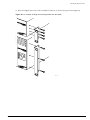
recommends placing no more than three BlackDiamond 6816 chassis next to each other.
The following are some general recommendations for installing your BlackDiamond 6816 chassis:
• A minimum of 17.32 inches (44 cm) between each set of three BlackDiamond 6816 chassis.
Or
• Place front-back cooled equipment, such as a BlackDiamond 6808 chassis, between each set of three
BlackDiamond 6816 chassis.
Or
• Place patch panels, which are used to patch cables together, between each set of three BlackDiamond
6816 chassis. A patch panel does not require any power and does not generate any heat.
NOTE
Up to five adjacent BlackDiamond 6816 chassis will continue to function without safety concerns.
However, product lifetime may degrade with continued exposure to high temperatures in close proximity
and long term reliability may be compromised.
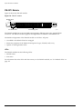
Airflow Requirements. To ensure proper airflow through an Extreme Networks switch, refer to the
following recommendations when you are installing your switch:
• The Summit family of switches require 3 inches (7.62 cm) on both the left and right sides of the
switch (5 inches (12.7 cm) recommended) for proper airflow.
• The Alpine 3800 series chassis require 3 inches (7.62 cm) on both the left and right sides of the switch
(5 inches (12.7 cm) recommended) for proper airflow.
• The BlackDiamond 6816 and 6804 chassis require 3 inches (7.62 cm) around the entire chassis—front,
rear, and sides—(5 inches (12.7 cm) recommended) for proper airflow.
Extreme Networks Consolidated Hardware Guide
39
Site Preparation
• The BlackDiamond 6808 chassis requires 3 inches (7.62 cm) around both the front and rear of the
chassis (5 inches (12.7 cm) recommended) for proper airflow.
The airflow of the Summit family of switches moves from the left side of the switch to the right side of
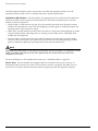
the switch, or from the right side of the switch to the left side of the switch depending on the model.
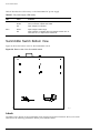
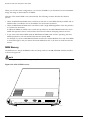
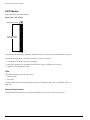
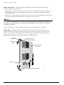
The airflow of the Alpine 3808 moves through the power supplies and is independent of the airflow
through the chassis as shown in Figure 4. For example, if the power supply fans fail, the airflow
through the module area of the chassis will not cool down the power supplies.
• Airflow for cooling power supplies enters the top of the chassis and moves left to right as you face
the chassis.
• Airflow for cooling modules moves left to right as you face the chassis.
Figure 4: Airflow through the Alpine 3808 chassis
Airflow
through
power
supplies
Airflow
through
chassis
Airflow
through
chassis
38_air8
The airflow of the Alpine 3804 and Alpine 3802 moves from the left side of the chassis to the right side
of the chassis as shown in Figure 5 and Figure 6.
• Airflow for cooling power supplies moves left to right as you face the chassis.
• Airflow for cooling modules moves left to right as you face the chassis.
40
Extreme Networks Consolidated Hardware Guide
Meeting Site Requirements
Figure 5: Airflow through the Alpine 3804 chassis
Airflow
through
chassis
Airflow
through
chassis
38_air4
Figure 6: Airflow through the Alpine 3802 chassis
Airflow
through
chassis
Airflow
through
chassis
3802air
Extreme Networks Consolidated Hardware Guide
41
Site Preparation
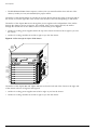
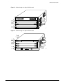
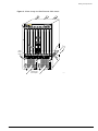
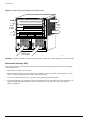
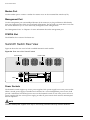
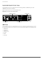
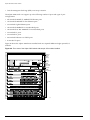
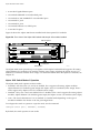
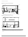
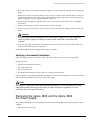
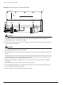
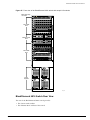
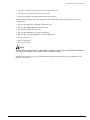
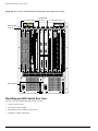
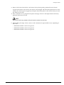
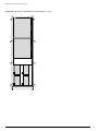
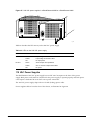
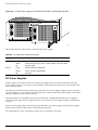
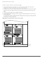
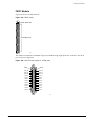
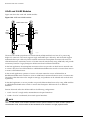
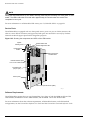
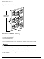
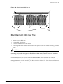
The airflow of the BlackDiamond 6800 series chassis moves through the power supplies and is
independent of the airflow through the modules as shown in Figure 7, Figure 8, and Figure 9. For
example, if the power supply fans fail, the airflow through the module area of the chassis will not cool
down the power supplies.
• Airflow for cooling power supplies moves front to back as you face the chassis.
• Airflow for cooling modules moves left to right as you face the chassis.
Figure 7: Airflow through the BlackDiamond 6816 chassis
1
2
3
4
5
6
7
8
A
B
C
D
9
10
11
12
Airflow
through
chassis
13
14
15
16
Airflow through
power supplies
42
BD_032
Extreme Networks Consolidated Hardware Guide
Meeting Site Requirements
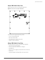
Figure 8: Airflow through the BlackDiamond 6808 chassis
1
2
3
4
A
B
50015
50015
5
6
7
8
Airflow
through
chassis
POWER
POWER
DC OUT
AC IN
50021
Airflow through
power supplies
Extreme Networks Consolidated Hardware Guide
DC OUT
AC IN
50021
BD_027
43
Site Preparation
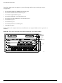
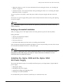
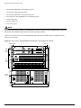
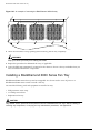
Figure 9: Airflow through the BlackDiamond 6804 chassis
Airflow
from
fan tray
Airflow
through
modules
Airflow through
power supplies
6804air
Humidity. Operating humidity should be kept between 10 and 95% relative humidity (noncondensing).
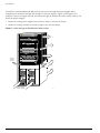
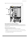
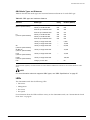
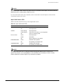
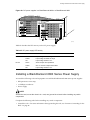
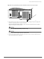
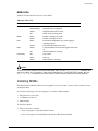
Electrostatic Discharge (ESD)
Your system must be protected from static electricity. Take the following measures to ensure optimum
system performance:
• Keep relative humidity at 50 to 70%.
• Remove materials that can cause electrostatic generation (such as synthetic resins) from the wiring
closet. Check the appropriateness of floor mats and flooring.
• Connect conductors (metals, etc.) to ground, using dedicated grounding lines.
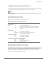
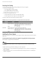
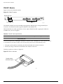
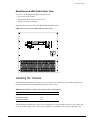
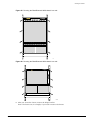
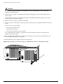
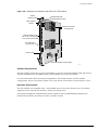
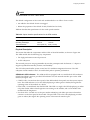
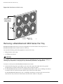
• Use electrostatically safe equipment and the ESD straps that are provided with your equipment. All
Alpine and BlackDiamond switches come with ESD wrist strap connectors and wrist straps as
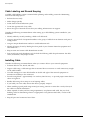
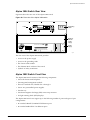
shown in Figure 10.
44
Extreme Networks Consolidated Hardware Guide
Meeting Site Requirements
Figure 10: Ensure that you use an ESD wrist strap when handling switch components
1
2
3
4
A
B
50015
50015
5
6
7
8
ESD strap
connector
Connected
wrist strap
POWER
POWER
DC OUT
AC IN
50020
DC OUT
AC IN
50020
SPG_003
Rack Specifications and Recommendations
Racks should conform to conventional standards. In the United States, use EIA Standard RS-310C:
Racks, Panels, and Associated Equipment. In countries other than the United States, use IEC Standard
297. In addition, verify that your rack meets the basic mechanical and space requirements that are
described in this section.
Mechanical Recommendations for the Rack
Use distribution racks that meet the following mechanical recommendations:
• Use an open style, 19-inch (48.26 cm) rack to facilitate easy maintenance and to provide proper
ventilation.
• The rack should use the universal mounting rail hole pattern that is identified in IEC Standard 297.
• The mounting holes should be flush with the rails to accommodate the chassis.
• Use a rack made of steel or aluminum.
Extreme Networks Consolidated Hardware Guide
45
Site Preparation
• Install equipment into the lower half of the rack first to avoid making the rack top-heavy.
• The rack should support approximately 600 pounds (272 kilograms).
Protective Grounding for the Rack
Use a rack grounding kit and a ground conductor that is carried back to earth or to another suitable
building ground.
All Extreme Networks switches are designed with mounting brackets that provide solid metal-to-metal
connection to the rack. If you do not use equipment racks, you can attach wiring terminals directly to
the mounting brackets for appropriate grounding. Alpine products have grounding terminals that are
mounted on the back of the chassis.
At minimum, follow these guidelines:
• Ground equipment racks to earth ground.
— CAD weld appropriate wire terminals to building I-beams or earth ground rods.
— Use #4 copper wire.
— Drill and tap wire terminals to equipment racks.
— Position the earth ground as close to the equipment rack as possible to maintain the shortest
wiring distance possible.
— Properly test the quality of the earth ground.
NOTE
Because building codes vary worldwide, Extreme Networks strongly recommends that you consult an
electrical contractor to ensure proper equipment grounding is in place for your specific installation.
• Ground DC power supplies to earth ground by using the grounding terminals provided.
Space Requirements for the Rack
Provide enough space in front of and behind the switch so that you can service it easily. Allow a
minimum of 48 inches (122 cm) in front of the rack and 24 inches (61 cm) behind the rack. When using a
relay rack, provide a minimum of 24 inches (61 cm) of space behind the mounted equipment. Extra
room on each side is optional.
NOTE
Install your equipment rack near an easily accessible power outlet. When you need to disconnect the
power cable from your switch, remove it first from the power source and then from the switch.
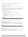
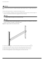
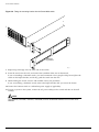
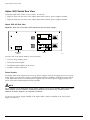
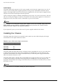
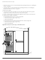
Securing the Rack
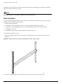
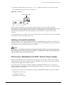
The rack should be attached to the wiring closet floor with 3/8 inch (9.5 mm) lag screws or equivalent
hardware. The floor under the rack should be level within 3/16 inch
(5 mm). Use a floor-leveling cement compound if necessary or bolt the racks to the floor as shown in
Figure 11.
46
Extreme Networks Consolidated Hardware Guide
Evaluating and Meeting Cable Requirements
Figure 11: Properly secured rack
Secure to floor
with 3/8 inch lag screws or bolts
SPG_007
Brace open distribution racks if the channel thickness is less than 1/4 inch (6.4 mm).
Evaluating and Meeting Cable Requirements
This section addresses requirements for the that cable you should use when installing your network
equipment. It includes:
• Cabling Standards
• Cable Labeling and Record Keeping
• Installing Cable
• RJ-45 Connector Jackets
• Radio Frequency Interference
Cabling Standards
We recommend using the BICSI (Building Industry Consulting Service International) RCDD (Registered
Communications Distribution Designer), which is globally recognized as a standard in site planning and
cabling. For information, go to http://www.bicsi.org
Extreme Networks Consolidated Hardware Guide
47
Site Preparation
Cable Labeling and Record Keeping
A reliable cable labeling system is essential when planning and installing a network. Maintaining
accurate records helps you to:
• Relocate devices easily.
• Make changes quickly.
• Isolate faults in the distribution system.
• Locate the opposite end of any cable.
• Know the types of network devices that your cabling infrastructure can support.
Consider the following recommendations when setting up a cable labeling system suitable for your
installation:
• Identify cables by securely attaching a label to all cable ends.
• Assign a unique block of sequential numbers to the group of cables that run between each pair of
wiring closets.
• Assign a unique identification number to each distribution rack.
• Identify all wiring closets by labeling the front panel of your Extreme Networks equipment and
other hardware.
• Keep accurate and current cable identification records.
• Post records near each distribution rack. Include the following cable drop information: the cable
source, destination, and jumper location.
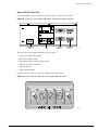
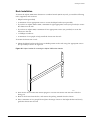
Installing Cable
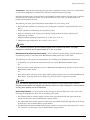
Consider the following recommendations when you connect cable to your network equipment:
• Examine cable for cuts, bends, and nicks.
• Support cable using a cable manager that is mounted above connectors to avoid unnecessary weight
on the cable bundles.
• Use cable managers to route cable bundles to the left and right of the network equipment to
maximize accessibility to the connectors.
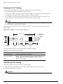
• Provide enough slack—approximately 2 to 3 inches (5.08-7.62 cm)— to provide proper strain relief as
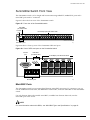
shown in Figure 12.
• Bundle cable using velcro straps to avoid injuring cables.
• If you build your own cable, ensure that cable is properly crimped.
• When installing a patch panel using twisted pair wiring, untwist no more than 1 inch (2.54 cm) of
the cable to avoid RF interference.
• When required for safety and fire rating requirements, use plenum-rated cable. See your local
building codes for determining when it is appropriate to use plenum-rated cable, or refer to IEC
standard 850.
• Keep all ports and connectors free of dust.
48
Extreme Networks Consolidated Hardware Guide
Evaluating and Meeting Cable Requirements
NOTE
Unshielded twisted pair (UTP) cable can build up ESD charges when being pulled into a new
installation. Before installing category 5 UTP cables, discharge ESD from the cable by plugging it into a
port on a switch or any network device that is not powered on.
Figure 12: Properly installed and bundled cable
Cable managers supporting
and directing cables
Proper
bundling
of cables
Adequate
slack, and
bend radius
SPG_008
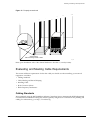
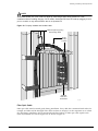
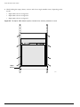
Fiber Optic Cable
Fiber optic cable must be treated gently during installation. Every cable has a minimum bend radius, for
example, and fibers will be damaged if the cables are bent too sharply. It is also important not to stretch
the cable during installation. We recommend that the bend radius for fiber optic cable equals 2-inch
(5.08 cm) minimum for each 90 degree turn as shown in Figure 13.
Extreme Networks Consolidated Hardware Guide
49
Site Preparation
NOTE
Kinks and sharp bends can destroy or impair the cable’s ability to convey light pulses accurately from
one end of the cable to the other. Use care in dressing the optical-fiber cables: provide satisfactory
strain relief to support the cable and maintain an adequate bend radius at all cable turns, particularly
where the cable connects to the I/O module.
Figure 13: Bend radius for fiber optic cable
Minimum
2 in. (5.08cm)
radius
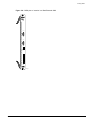
in 90˚ bend
90˚
Optical fiber cable
SPG_002
Cable Distances
Table 18 shows cable media types and maximum distances that support reliable transmission in
accordance with international standards except where noted.
Table 18: Media types and maximum distances
Standard
Media Type
Mhz•Km
Rating
Maximum Distance
(Meters)
1000BASE-SX
(850 nm optical
window)
50/125 µm multimode fiber
400
500
50/125 µm multimode fiber
500
550
62.5/125 µm multimode fiber
160
220
62.5/125 µm multimode fiber
200
275
50/125 µm multimode fiber
400
550
50/125 µm multimode fiber
500
550
62.5/125 µm multimode fiber
500
550
10/125 µm single-mode fiber
–
5,000
10/125 µm single-mode fiber*
–
10,000
1000BASE-LX70
(1550 nm optical
window)
10/125 µm single-mode fiber
–
70,000
100BASE-FX
(1300 nm optical
window)
50/125 µm multimode fiber
400
2000
50/125 µm multimode fiber
500
2000
62.5/125 µm multimode fiber
400
2000
62.5/125 µm multimode fiber
500
2000
1000BASE-LX
(1300 nm optical
window)
50
Extreme Networks Consolidated Hardware Guide
Evaluating and Meeting Cable Requirements
Table 18: Media types and maximum distances (continued)
Mhz•Km
Rating
Maximum Distance
(Meters)
Standard
Media Type
1000BASE-T
Category 5 and higher UTP cable
–
100
100BASE-TX
Category 5 and higher UTP cable
–
100
10BASE-T
Category 3 and higher UTP cable
–
100
*
Proprietary to Extreme Networks. Connections between two Extreme Networks 1000BASE-LX interfaces that use 10/125 µm
single-mode fiber can use a maximum distance of 10,000 meters.
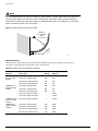
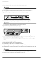
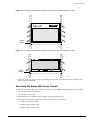
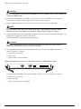
RJ-45 Connector Jackets
Use RJ-45 cable with connector jackets that are flush with the connector or that have connectors with a
no-snag feature.
Using cable with jackets that are wider than the connectors can cause:
• Connectors that are not properly aligned with the port.
• Crowded cable installation, which can cause connectors to pop out of the port.
Figure 14 shows examples of connector jacket types that are not recommended as well as those that are
recommended.
Figure 14: RJ-45 connector jacket types
Not recommended
Best
Better
0.1" = 1mm actual
39.37% : 254%
SPG_001
Radio Frequency Interference
If you use unshielded twisted pair (UTP) cabling in an installation, take precautions to avoid radio
frequency (RF) interference. RF interference can cause degradation of signal quality, and, in an Ethernet
Extreme Networks Consolidated Hardware Guide
51
Site Preparation
network environment, can cause excessive collisions, loss of link status, or other physical layer problems
that can lead to poor performance or loss of communication.
To prevent RF interference, avoid the following devices or situations:
• Attaching UTP cable to AC power cables
• Routing UTP cable near antennas, such as a Ham radio antenna
• Routing UTP cable near equipment that could exhibit RF interference, such as:
— ARC welding equipment
— Electrical motors that contain coils
— Air conditioner units
— Electrical transformers
In areas or applications where these situations cannot be avoided, use fiber optic cabling or shielded
twisted pair cabling (STP).
NOTE
Because harmonics can appear on the neutral line of a typical three-phase power circuit, Extreme
Networks recommends using a harmonics meter in new installations.
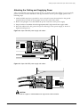
Making Network Interface Cable Connections
Use the appropriate type of cable to connect the ports of your switch to another switch or router.
Working carefully, one port at a time, follow these steps:
1 Verify that you have identified the correct cable for the port.
2 Use an alcohol wipe or other appropriate cleaning agent to clean the cable connectors; make sure
they are free of dust, oil, and other contaminants.
3 If you are using optical-fiber cable, align the transmit (Tx) and receive (Rx) connectors with the
correct corresponding connectors on the switch or the I/O module.
On the ATM and PoS modules, the transmit (Tx) connector on each port is the top connector.
4 Press the cable connectors into their mating connectors on the switch or I/O module until the cable
connector is firmly seated.
5 Repeat steps 1 through 4 for the remaining cables on this or other switches or I/O modules.
6 Dress and secure the cable bundle to provide appropriate strain relief and protection against bends
and kinks.
Meeting Power Requirements
This section discusses power requirements, including:
• Power Supply Requirements
• AC Power Cable Requirements
• Uninterruptable Power Supply Requirements
52
Extreme Networks Consolidated Hardware Guide
Meeting Power Requirements
For more information about the power specifications of the Extreme Networks family of switches, see
Appendix B, “Switch Technical Specifications” on page 299.
Power Supply Requirements
Adhere to the following requirements in order to operate your Extreme Networks equipment safely:
• Ensure that your equipment is placed in an area that accommodates the power consumption and
component heat dissipation specifications.
• Ensure that your power supply meets the site power, AC power, or DC power requirements of the
network equipment.
• Ensure that DC connections are made by an on-site electrician.
NOTE
For power specifications for Extreme Networks products, see the Extreme Networks website at
http://www.extremenetworks.com.
• When connecting power to installed equipment, avoid connecting through an extension cord or
power strip.
• If your switch includes more than one power supply, connect each power supply to different,
independent power sources. If a power source fails, it will only affect the switch power supply to
which it is connected. If all switch power supplies are connected to a single power source, the entire
switch is vulnerable to a power source failure.
AC Power Cable Requirements
Use an AC power cable appropriate for your country. Check your local electrical codes and regulatory
agencies for power cable requirements. The countries listed in Table 19 have the following additional
requirements:
Table 19: AC power cable requirements
Country
Requirements
USA and Canada
•
The cable set must be UL-approved and CSA-certified.
•
The minimum specification for the flexible cable is No. 18
AWG (1.5 mm 2), Type SVT or SJT, 3-conductor.
•
The cable set must have a rated current capacity of at least
the amount rated for each specific product.
•
The attachment plug must be an Earth-grounding type with
a NEMA 5-15P (10 A, 125 V) configuration.
Denmark
The supply plug must comply with section 107-2-D1, standard
DK2-1a or DK2-5a.
Switzerland
The supply plug must comply with SEV/ASE 1011.
Argentina
The supply plug must comply with Argentinian standards.
Extreme Networks Consolidated Hardware Guide
53
Site Preparation
NOTE
When using dual power supplies, make sure that each AC power supply attaches to an independent
power source.
Replacing the Power Cable
If the power cable plug is unsuitable and must be replaced, connect the power supply wires for the
switch according to the following scheme:
• Brown wire to the Live (Line) plug terminal, which may be marked with the letter “L” or colored
red.
• Blue wire to the Neutral plug terminal, which may be marked with the letter “N” or colored black.
• Yellow/Green wire to the Ground plug terminal, which may be marked with the letter “E” (the
Earth symbol) or colored yellow/green.
Uninterruptable Power Supply Requirements
An uninterruptible power supply (UPS) is a device that sits between a power supply (such as a wall
outlet) and a device (such as a switch) to prevent outages, sags, surges, and bad harmonics from
adversely affecting the performance of the device.
UPS Features
A UPS traditionally can perform the following functions:
• Absorb relatively small power surges.
• Smooth out noisy power sources.
• Continue to provide power to equipment during line sags.
• Provide power for some time after a blackout has occurred.
In addition, some UPS or UPS plus software combinations provide the following functions:
• Automatic shutdown of equipment during long power outages.
• Monitoring and logging of power supply status.
• Display the voltage (current draw) of the equipment.
• Restart equipment after a long power outage.
• Display the voltage currently on the line.
• Provide alarms on certain error conditions.
• Provide short circuit protection.
Selecting a UPS
To determine UPS requirements for your switch, ask these questions:
• What are the amperage requirements?
• What is the longest potential time period that the UPS would be required to supply backup power?
• Where will the UPS be installed?
• What is the maximum transition time that your installation will allow?
54
Extreme Networks Consolidated Hardware Guide
Applicable Industry Standards
NOTE
Extreme Networks recommends that you use a UPS that provides online protection.
Calculating Amperage Requirements
To determine the size of UPS that you need, use the following procedure:
1 To find VA (Volt-Amps), locate the voltage and amperage requirements for each piece of equipment.
These numbers are usually located on a sticker on the back or bottom of your equipment. Then
multiply the numbers together to get VA:
VA = Volts x Amperes
2 Add the VA from each piece of equipment together to find the total VA requirement.
To determine the minimum amperage requirements for your UPS, we recommend that you add 30%
to the total.
UPS Transition Time
Transition time is the time that is necessary for the UPS to transfer from utility power to full-load
battery power. For Extreme Networks products, a transition time of less than 20 milliseconds is required
for optimum performance.
Applicable Industry Standards
For more information, see the following ANSI/TIA/EIA standards:
• ANSI/TIA/EIA-568-A—discusses the six subsystems of a structured cabling system.
• ANSI/TIA/EIA-569-A—discusses design considerations.
• ANSI/TIA/EIA-606—discusses cabling system administration.
• ANSI/TIA/EIA-607—discusses commercial building grounding and bonding requirements.
You can access these standards at http://www.ansi.org/ or http://www.tiaonline.org/.
Extreme Networks Consolidated Hardware Guide
55
Site Preparation
56
Extreme Networks Consolidated Hardware Guide
Part 3
Summit Switch
3
Summit Switch Overview
This chapter describes:
• Summit Switch Models on page 59
• Summary of Features on page 60
• Memory Requirements on page 62
• Following Safety Information on page 63
Summit Switch Models
The following models comprise the Summit family of switches:
• Summit1i
• Summit5i
• Summit7i
• Summit48i
• Suumit48si
• Summit 200-24
• Summit 200-48
Extreme Networks Consolidated Hardware Guide
59
Summit Switch Overview
Summary of Features
This section describes the features of the Summit family of switches. If the information in the release
notes differs from the information in this guide, follow the release notes. For more information about
configuring the switch, refer to the ExtremeWare Software User Guide and The ExtremeWare Command
Reference Guide.
Summit “i” series switches
• Virtual local area networks (VLANs), including support for IEEE 802.1Q and IEEE 802.1p
• VLAN aggregation
• Spanning Tree Protocol (STP) (IEEE 802.1D) with multiple STP domains
• Policy-Based Quality of Service (PB-QoS)
• Wire-speed Internet Protocol (IP) routing
• IP multinetting
• DHCP/BOOTP relay
• Extreme Standby Router Protocol (ESRP)
• Ethernet Automated Protection Switching (EAPS)
• Routing Information Protocol (RIP) version 1 and RIP version 2
• Open Shortest Path First (OSPF) routing protocol
• Border Gateway Protocol (BGP) version 4
• IPX routing, including RIP and Service Advertisement Protocol (SAP)
• Wire-speed IP multicast routing
• DiffServ
• Access-policy support for routing protocols
• Access list support for packet filtering
• IGMP snooping
• Distance Vector Multicast Routing Protocol (DVMRP)
• Protocol Independent Multicast-Dense Mode (PIM-DM)
• Protocol Independent Multicast-Sparse Mode (PIM-SM)
• Wire-speed IPX, IPX/RIP, and IPX/SAP
• Server Load Balancing (SLB)
• RADIUS client and per-command authentication
• TACACS+
• Console command-line interface (CLI) connection
• Telnet CLI connection
• SSH2 connection
• ExtremeWare® Vista™ Web-based management interface
• Simple Network Management Protocol (SNMP)
60
Extreme Networks Consolidated Hardware Guide
Summary of Features
• Remote Monitoring (RMON)
• Adjustable fan speed based on the temperature of the switch (Summit48si only)
Summit 200 Series
• VLANs including support for IEEE 802.1Q and IEEE 802.1p
• STP (IEEE 802.1D)
• QoS including support for IEEE 802.1p, MAC QoS, and four hardware queues
• Wire-speed IP routing
• DHCP/BOOTP Relay
• NAT
• ESRP-Aware support
• EAPS support
• RIP version 1 and RIP version 2
• OSPF routing protocol
• DiffServ support
• Access-policy support for routing protocols
• Access list support for packet filtering
• Access list support for rate-limiting
• IGMP snooping to control IP multicast traffic
• Load sharing on multiple ports
• RADIUS client and per-command authentication support
• TACACS+ support
• Network Login
• CLI connection
• Telnet CLI connection
• SSH2 connection
• SNMP
• Remote Monitoring (RMON)
• Traffic mirroring for ports
Extreme Networks Consolidated Hardware Guide
61
Summit Switch Overview
Memory Requirements
Your “i” series Summit switch must have 128MB of DRAM in order to support the features in
ExtremeWare version 6.0 or later.
To determine the memory size in your switch, use the following command:
show memory
For Summit switches running ExtremeWare 4.0 or later, the switch indicates the total DRAM size in
megabytes as part of the output. For Summit switches running ExtremeWare releases prior to 4.0, you
must calculate the memory by taking the sum of the bytes listed under current free and adding to it
the bytes listed under current alloc. If the sum is greater than 16,000,000, there is no need to upgrade
the memory on the switch. If this is not the case, please contact your supplier.
Port Connections
Summit switches use a combination of the following types of ports:
• 1000BASE-SX ports using 850 nm duplex SC connectors
• 1000BASE-LX ports using 1300 nm duplex SC connectors
• 1000BASE-LX ports using 1300 nm duplex LC connectors
• 1000BASE-SX ports using MT-RJ connectors
• 1000BASE-LX ports using MT-RJ connectors
• Modular 1000BASE-SX, 1000BASE-LX, and IEEE 802.3z standard using mini-Gigabit Interface
Connectors (mini-GBICs)
• Modular 1000BASE-SX, 1000BASE-LX, 1000BASE-ZX, LX100, and UTP using Gigabit Interface
Connectors (GBICs)
— The UTP GBIC is supported on “i” series switches only
• 10BASE-T/100BASE-TX ports using RJ-45 connectors
• 100BASE-FX ports using 1300 nm duplex SC connectors
• 100BASE-TX/1000BASE-T ports using RJ-45 connectors
Table 20 describes port configurations available on the different Summit switch models.
Table 20: Port configurations on all Summit switch models
Ethernet Ports
Switch Model
1000BASE- 1000BASE- 100/1000
SX
LX
BASE-T GBIC
Summit1i SX
6
2
Summit1i TX
Summit5i SX
6
12
Summit5i LX
Summit7i SX
62
4
12
28
2
4
12
Summit5i TX
10BASE-T/
Redundant 100BASE- 100BASEGBIC
FX
Other
TX
4
4
Extreme Networks Consolidated Hardware Guide
Following Safety Information
Table 20: Port configurations on all Summit switch models (continued)
Ethernet Ports
Switch Model
1000BASE- 1000BASE- 100/1000
SX
LX
BASE-T GBIC
Summit7i TX
28
10BASE-T/
Redundant 100BASE- 100BASEGBIC
FX
Other
TX
4
Summit48i
2
2
48
Summit48si
2
48
Summit 200-24
2*
24
2*
Summit 200-48
2*
48
2*
* The Summit 200 series switch has two 10/100/1000BASE-T Gigabit Ethernet uplink ports using RJ-45 connectors and two
optical ports that also allow Gigabit Ethernet uplink connections through mini-GBICs using optical fibers with LC connectors.
Following Safety Information
WARNING!
Read the safety information in Appendix A thoroughly before installing your Extreme Networks switch.
Failure to follow this safety information can lead to personal injury or damage to the equipment.
• All service to components of a Summit series switch should be performed by trained service
personnel only. Service personnel are persons having appropriate technical training and experience
necessary to be aware of the hazards to which they are exposed in performing a task and of
measures to minimize the danger to themselves or other persons.
• Some devices, such as GBICs, contain fiber optic ports. To protect your eyes, you should never look
at the fiber optic ports while they are on, or look directly at the fiber cable ends when they are on.
Extreme Networks Consolidated Hardware Guide
63
Summit Switch Overview
64
Extreme Networks Consolidated Hardware Guide
4
Summit Switch Models
This chapter describes:
• Front and rear views of the Summit switch models
• LEDs on the Summit switch models
Switch Models
The following models comprise the Summit family of switches:
• Summit1i on page 66
• Summit5i on page 69
• Summit7i on page 73
• Summit48i on page 78
• Summit48si on page 81
• Summit 200-24 on page 85
• Summit 200-48 on page 89
Extreme Networks Consolidated Hardware Guide
65
Summit Switch Models
Summit1i Switch Front View
As shown in Figure 15 and Figure 16, the Summit1i switch is 2U in height and is available in two port
configurations:
• Six autosensing 100BASE-TX/1000BASE-T ports with RJ-45 connectors and two 1000BASE-X ports
with SC connectors
• Six 1000BASE-SX ports with MT-RJ connectors and two 1000BASE-X ports with SC connectors
Figure 15: Front view of the Summit1i switch with 100BASE-TX/1000BASE-T ports
100/1000 Mbps ports
TOP ROW:
GREEN
= 1000Mbps
BOTTOM ROW:
AMBER
GREEN
FLASHING GREEN
= ACTIVITY
= LINK OK
= DISABLED
1
2
3
100BASE-TX/
1000BASE-T
4
5
Unit status LEDs
6
7
1000BASE-X
8
PSU A
PSU B
1
2
3
4
5
6
7
8
MGMT
Port status LEDs
Gigabit Ethernet ports
SHG_S1T
Figure 16: Front view of the Summit1i switch with 1000BASE-SX ports
1000 Mbps ports
1
1
2
3
4
5
6
7
2
3
4
Unit status LEDs
5
6
7
8
8
Port status LEDs
Gigabit Ethernet ports
SHG_S1SX
GBIC Ports
Both Summit1i switch models provide two unpopulated GBIC ports with SC connectors. You can use
the following GBICs in the Summit1i switch:
• 1000BASE-SX
• 1000BASE-LX
• 1000BASE-LX70
• ZX GBIC
• LX100
• UTP GBIC
66
Extreme Networks Consolidated Hardware Guide
Summit1i Switch Front View
GBIC Media Types and Distances
Table 21 describes the media types and associated maximum distances for each GBIC type.
Table 21: GBIC types and maximum distances
Standard
Media Type
Mhz•Km
Rating
Maximum
Distance (Meters)
SX
(850 nm optical window)
50/125 µm multimode fiber
400
500
50/125 µm multimode fiber
500
550
62.5/125 µm multimode fiber
160
220
62.5/125 µm multimode fiber
200
275
50/125 µm multimode fiber
400
550
50/125 µm multimode fiber
500
550
62.5/125 µm multimode fiber
500
550
10/125 µm single-mode fiber
–
5,000
10/125 µm single-mode fiber*
–
10,000
ZX
(1550 nm optical window)
10/125 µm single-mode fiber
–
50,000
ZX Rev 03
(1550 nm optical window)
10/125 µm single-mode fiber
LX70
(1550 nm optical window)
10/125 µm single-mode fiber
LX100
(1550 nm optical window)
10/125 µm single-mode fiber
UTP
Category 5 UTP cable
LX
(1310 nm optical window)
70,000
–
70,000
100,000
–
80
*Extreme Networks proprietary. Connections between two Extreme Networks 1000BASE-LX interfaces can use a maximum distance of 10,000
meters.
NOTE
For more information about the supported GBIC types, see “GBIC Specifications” on page 25.
LEDs
Both Summiti1 models have the following LEDs:
• Unit status
• Management
• Port status
• Port speed
For information about the LEDs and their activity on the Summit1i switch, see “Summit1i, Summit5i,
Summit7i, and Summit48i Switch LEDs” on page 77.
Extreme Networks Consolidated Hardware Guide
67
Summit Switch Models
Summit1i Switch Rear View
Figure 17 shows the rear view for both available Summit1i switch models.
Figure 17: Rear view of the Summit1i switch
AC Connectors
Label
Reset button
Console port
SHG_Rr1
Power Sockets
The Summit1i switch supports up to two power supplies. Each power supply has its own power socket.
When a second power supply is installed and connected to a second independent power source, both
provide a redundant, load-shared power source to the Summit1i switch. If one of the power sources or
power supplies fails, the second power supply provides all power needs which ensures uninterrupted
network operation.
CAUTION
Service to Summit1i power supplies should be performed by trained service personnel only.
Label
The label on the rear of the Summit1i switch displays important information about your switch. Write
down the following information before you install the switch:
• Model number—Shows the model number assigned to this device
• Part number—Shows the part number assigned to this device
• Serial number—Refer to the serial number when you contact Extreme Networks technical support
• MAC address—Shows the unique Ethernet MAC address assigned to this device
Reset Button
Use the reset button to cycle the switch down and bring the switch back up without powering off the
switch. Your saved switch configuration information is not lost; unsaved switch configurations are lost.
Use a non-conductive tool to push the reset button.
Console Port
Use the console port (9-pin, “D” type connector) to attach a terminal and access the CLI via a serial
connection. Use the console port for local management.
68
Extreme Networks Consolidated Hardware Guide
Summit5i Switch Front View
Summit5i Switch Front View
As shown in Figure 18, Figure 19, and Figure 20, the Summit5i switch is 2U in height and is available in
three port configurations:
• 12 autosensing 100BASE-TX/1000BASE-T ports with RJ-45 connectors and 4 1000BASE-X ports with
SC connectors
• 12 1000BASE-SX ports with MT-RJ connectors and 4 1000BASE-X ports with SC connectors
• 12 1000BASE-LX ports with either MT-RJ or LC connectors (Figure 20 shows LC connectors) and
4 1000BASE-X ports with SC connectors
To determine the type of connectors on your Summit5iLX switch, look at the serial number on the
rear of the switch. Serial numbers that start with 0233 and lower have MT-RJ connectors. Serial
numbers that start with 0234 and higher have LC connectors. For example, a Summit5iLX switch
with the serial number 0234M-00012 has LC connectors.
Figure 18: Front view of the Summit5i switch with 100BASE-TX/1000BASE-T ports
100/1000 Mbps ports
TOP ROWS:
GREEN
1
2
3
1
2
3
4
9
10
11
12
100BASE-TX/
1000BASE-T
5
Unit status LEDs
6
7
8
= 1000Mbps
4
5
BOTTOM ROWS:
AMBER
GREEN
FLASHING GREEN
6
7
8
= ACTIVITY
= LINK OK
= DISABLED
13
1000BASE-X
14
15
16
PSU A
PSU B
9
10
11
12
13
14
15
16
MGMT
Port status LEDs
Gigabit Ethernet ports
SHG_S5T
Figure 19: Front view of the Summit5i switch with 1000BASE-SX ports
1000 Mbps ports
1
2
3
4
9
10
11
12
ort status LEDs
Extreme Networks Consolidated Hardware Guide
5
13
Unit status LEDs
6
14
7
8
15
Gigabit Ethernet ports
16
SHG_S5SX
69
Summit Switch Models
Figure 20: Front view of the Summit5i switch with 1000BASE-LX ports
1000 Mbps ports
1
2
3
4
9
10
11
12
5
13
ort status LEDs
Unit status LEDs
6
14
7
8
15
16
Gigabit Ethernet ports
SHG_S5LX
GBIC Ports
All three Summit5i switch models provide four unpopulated GBIC ports with SC connectors. You can
use the following GBICs in the Summit5i switch:
• 1000BASE-SX
• 1000BASE-LX
• 1000BASE-LX70
• ZX GBIC
• LX100
• UTP GBIC
GBIC Media Types and Distances
Table 22 describes the media types and associated maximum distances for each GBIC type.
Table 22: GBIC types and maximum distances
Standard
Media Type
Mhz•Km
Rating
Maximum
Distance (Meters)
SX
(850 nm optical window)
50/125 µm multimode fiber
400
500
50/125 µm multimode fiber
500
550
62.5/125 µm multimode fiber
160
220
62.5/125 µm multimode fiber
200
275
50/125 µm multimode fiber
400
550
50/125 µm multimode fiber
500
550
62.5/125 µm multimode fiber
500
550
10/125 µm single-mode fiber
–
5,000
10/125 µm single-mode fiber*
–
10,000
ZX
(1550 nm optical window)
10/125 µm single-mode fiber
–
50,000
ZX Rev 03
(1550 nm optical window)
10/125 µm single-mode fiber
LX70
(1550 nm optical window)
10/125 µm single-mode fiber
LX
(1310 nm optical window)
70
70,000
–
70,000
Extreme Networks Consolidated Hardware Guide
Summit5i Switch Rear View
Table 22: GBIC types and maximum distances (continued)
Standard
Media Type
LX100
(1550 nm optical window)
10/125 µm single-mode fiber
UTP
Category 5 UTP cable
Mhz•Km
Rating
Maximum
Distance (Meters)
100,000
–
80
*Extreme Networks proprietary. Connections between two Extreme Networks 1000BASE-LX interfaces can use a maximum distance of 10,000
meters.
NOTE
For more information about the supported GBIC types, see “GBIC Specifications” on page 25.
LEDs
All three Summit5i models have the following LEDs:
• Unit status
• Management
• Port status
• Port speed
• Management port
For information about the LEDs and their activity on the Summit5i switch, see “Summit1i, Summit5i,
Summit7i, and Summit48i Switch LEDs” on page 77.
Summit5i Switch Rear View
Figure 21 shows the rear view for the Summit5i switch.
Figure 21: Rear view of the Summit5i switch
AC Connectors
Label
Reset button
Console port
Ethernet port
SHG_Rr5
Power Sockets
The Summit5i switch supports up to two power supplies. Each power supply has its own power socket.
When a second power supply is installed and connected to a second independent power source, both
provide a redundant, load-shared power source to the Summit5i switch. If one of the power sources or
Extreme Networks Consolidated Hardware Guide
71
Summit Switch Models
power supplies fails, the second power supply provides all power needs which ensures uninterrupted
network operation.
NOTE
Summit5i switch power supplies must be serviced by personnel trained by Extreme Networks, only.
Label
The label on the rear of the Summit5i switch displays important information about your switch. Write
down your switch information before you install the switch:
• Model number—Shows the model number assigned to this device
• Part number—Shows the part number assigned to this device
• Serial number—Refer to the serial number when you contact Extreme Networks technical support
• MAC address—Shows the unique Ethernet MAC address assigned to this device
Reset Button
Use the reset button to cycle the switch down and bring the switch back up without powering off the
switch. Your saved switch configuration information is not lost; unsaved switch configurations are lost.
Use a non-conductive tool to push the reset button.
Console Port
Use the console port (9-pin, “D” type connector) to attach a terminal and access the CLI via a serial
connection. Use the console port for local management.
Management Port
Use the management port (10/100 Mbps Ethernet, RJ-45 connector) to plug an Ethernet cable directly
from your laptop into the switch for out-of-band management. This provides you with direct access into
the switch and allows you to view and locally manage the switch configurations.
See “Management Ports” in Chapter 1 for more information about the management port.
72
Extreme Networks Consolidated Hardware Guide
Summit7i Switch Front View
Summit7i Switch Front View
As shown in Figure 22 and Figure 23, the Summit7i switch is 4U in height and is available in two port
configurations:
• 28 autosensing 100BASE-TX/1000BASE-T ports with RJ-45 connectors and 4 1000BASE-X ports with
SC connectors
• 28 1000BASE-SX ports with MT-RJ connectors and 4 1000BASE-SX ports with SC connectors
Figure 22: Front view of the Summit7i switch with 100BASE-TX/1000BASE-T ports
Module status
LEDs
Console
port
Reset
button
Management
port
Modem
port
Management
port LED
PCMCIA slot
PSU A
PSU B
MGMT
LINK/ACTIVITY
CONSOLE
1
2
3
4
5
TOP ROWS:
GREEN
6
7
PCMCIA
10BASE-T/100BASE-TX
MGMT PORT
MODEM
1
2
3
4
5
6
7
8
9
10
11
12
13
14
15
16
17
18
19
20
21
22
23
24
25
26
27
28
8
= 1000 Mbps
9 10 11 12 13 14 15 16
BOTTOM ROWS:
AMBER
GREEN
FLASHING GREEN
= ACTIVITY
= LINK OK
= DISABLED
17 18 19 20 21 22 23 24
29
30
31
32
25 26 27 28 29 30 31 32
Port status
LEDs
100/1000 Mbps ports
Extreme Networks Consolidated Hardware Guide
Gigabit Ethernet ports
EW_S7iTX
73
Summit Switch Models
Figure 23: Front view of the Summit7i switch with 1000BASE-SX ports
Module status
LEDs
Console
port
Reset
button
Management
port
Modem
port
Management
port LED
PCMCIA slot
PSU A
PSU B
MGMT
LINK/ACTIVITY
CONSOLE
1
2
3
4
5
6
7
8
MODEM
PCMCIA
10BASE-T/100BASE-TX
MGMT PORT
1
2
3
4
5
6
7
8
9
10
11
12
13
14
15
16
17
18
19
20
21
22
23
24
25
26
27
28
9 10 11 12
13 14 15 16
AMBER
GREEN
FLASHING GREEN
= ACTIVITY
= LINK OK
= DISABLED
17 18 19 20
21 22 23 24
29
30
31
32
25 26 27 28
29 30 31 32
Port status
LEDs
1000BASE-SX ports
Gigabit Ethernet ports
EW_S7iSX
GBIC Ports
Both Summit7i switch models provide four unpopulated GBIC ports with SC connectors. You can use
the following GBICs in the Summit7i switch:
• 1000BASE-SX
• 1000BASE-LX
• 1000BASE-LX70
• ZX GBIC
• LX100
• UTP GBIC
GBIC Media Types and Distances
Table 23 describes the media types and associated maximum distances for each GBIC type.
Table 23: GBIC types and maximum distances
Standard
Media Type
Mhz•Km
Rating
Maximum
Distance (Meters)
SX
(850 nm optical window)
50/125 µm multimode fiber
400
500
50/125 µm multimode fiber
500
550
62.5/125 µm multimode fiber
160
220
62.5/125 µm multimode fiber
200
275
74
Extreme Networks Consolidated Hardware Guide
Summit7i Switch Front View
Table 23: GBIC types and maximum distances (continued)
Standard
Media Type
Mhz•Km
Rating
Maximum
Distance (Meters)
LX
(1310 nm optical window)
50/125 µm multimode fiber
400
550
50/125 µm multimode fiber
500
550
62.5/125 µm multimode fiber
500
550
10/125 µm single-mode fiber
–
5,000
10/125 µm single-mode fiber*
–
10,000
ZX
(1550 nm optical window)
10/125 µm single-mode fiber
–
50,000
ZX Rev 03
(1550 nm optical window)
10/125 µm single-mode fiber
LX70
(1550 nm optical window)
10/125 µm single-mode fiber
LX100
(1550 nm optical window)
10/125 µm single-mode fiber
UTP
Category 5 UTP cable
70,000
–
70,000
100,000
–
80
*Extreme Networks proprietary. Connections between two Extreme Networks 1000BASE-LX interfaces can use a maximum distance of 10,000
meters.
NOTE
For more information about the supported GBIC types, see “GBIC Specifications” on page 25.
LEDs
Both Summit7i models have the following LEDs:
• Unit status
• Management
• Port status
• Port speed
• Management port
For information about the LEDs and their activity on the Summit7i switch, see “Summit1i, Summit5i,
Summit7i, and Summit48i Switch LEDs” on page 77.
Reset Button
Use the reset button to cycle the switch down and bring the switch back up without powering off the
switch. Your saved switch configuration information is not lost; unsaved switch configurations are lost.
Use a non-conductive tool to push the reset button.
Console Port
Use the console port (9-pin, “D” type connector) to attach a terminal and access the CLI via a serial
connection. Use the console port for local management.
Extreme Networks Consolidated Hardware Guide
75
Summit Switch Models
Modem Port
Use the modem port to connect a modem for remote access to the command line interface (CLI).
Management Port
Use the management port (10/100 Mbps Ethernet, RJ-45 connector) to plug an Ethernet cable directly
from your laptop into the switch for out-of-band management. This provides you with direct access into
the switch and allows you to view and locally manage the switch configurations.
See “Management Ports” in Chapter 1 for more information about the management port.
PCMCIA Slot
The PCMCIA slot is reserved for future use.
Summit7i Switch Rear View
Figure 24 shows the rear view for both available Summit7i switch models.
Figure 24: Rear view of the Summit7i switch
Power socket
Power socket
Label
EW_S7iRr
Power Sockets
The Summit7i switch supports up to two power supplies. Each power supply has its own power socket.
When a second power supply is installed and connected to a second independent power source, both
provide a redundant, load-shared power source to the Summit7i switch. If one of the power sources or
power supplies fails, the second power supply provides all power needs which ensures uninterrupted
network operation.
NOTE
Summit7i switch power supplies must only be serviced by personnel trained by Extreme Networks.
76
Extreme Networks Consolidated Hardware Guide
Summit1i, Summit5i, Summit7i, and Summit48i Switch LEDs
Label
The label on the rear of the Summit7i switch displays important information about your switch. Write
down the following information before you install the switch:
• Model number—Shows the model number assigned to this device
• Part number—Shows the part number assigned to this device
• Serial number—Refer to the serial number when you contact Extreme Networks technical support
• MAC address—Shows the unique Ethernet MAC address assigned to this device.
Summit1i, Summit5i, Summit7i, and Summit48i Switch
LEDs
Table 24 describes the LED activity on the Summit1i, Summit5i, Summit7i, and Summit48i switches.
Table 24: Switch LED activity for the Summit1i, Summit5i, Summit7i, and Summit48i
LED
Color
Indicates
Green
The indicated PSU is powered up.
Amber
The indicated PSU has a failure.
Green/Amber
blinking
The AC power cable is not inserted correctly.
Off
The PSU is not receiving power or no PSU is present.
Green
The switch is operating normally.
Unit Status LEDs
PSU A, PSU B
MGMT
Power On Self Test (POST) or software download in progress.
Amber
The switch has failed its POST or is experiencing an overheat or
fan failure.
Green
Link is present; port is enabled.
Amber
Frames are being transmitted/received on this port.
Green blinking
Link is present; port is disabled.
Off
Link is not present.
Port Status LEDs
100/1000 Mbps Speed LEDs
Green
Port is operating at 1000 Mbps.
Off
Port is operating at 100 Mbps.
10/100 Management Port LED (Summit5i and Summit7i)
Green
Link is present.
Amber
Frames are being transmitted.
Off
Link is not present.
Extreme Networks Consolidated Hardware Guide
77
Summit Switch Models
Summit48i Switch Front View
The Summit48i switch is 2U in height and has 48 autosensing 10BASE-T/100BASE-TX ports and 4
1000BASE-X ports with SC connectors.
Figure 25 shows the front view of the Summit48i switch.
Figure 25: Front view of the Summit48i switch
Gigabit Ethernet ports
49
49R
50
Unit status LEDs
1
2
3
4
5
6
7
8
50R
49 49R
50 50R
Port status LEDs
17
18
19
20
21
22
23
24
9
25
10
26
11
27
12
28
13
29
14
30
15
31
16
32
33
34
35
36
37
38
39
40
41
42
43
44
45
46
47
48
10/100 Mbps ports
S48i_fr
GBIC Ports
The Summit48i switch has two Gigabit Ethernet ports and two redundant Gigabit Ethernet ports. All of
the Gigabit Ethernet ports use SC connectors. You can use the following GBICs in the Summit48i switch:
• 1000BASE-SX
• 1000BASE-LX
• 1000BASE-LX70
• ZX GBIC
• LX100
• UTP GBIC
78
Extreme Networks Consolidated Hardware Guide
Summit48i Switch Front View
GBIC Media Types and Distances
Table 25 describes the media types and associated maximum distances for each GBIC type.
Table 25: GBIC types and maximum distances
Standard
Media Type
Mhz•Km
Rating
Maximum
Distance (Meters)
SX
(850 nm optical window)
50/125 µm multimode fiber
400
500
50/125 µm multimode fiber
500
550
62.5/125 µm multimode fiber
160
220
62.5/125 µm multimode fiber
200
275
50/125 µm multimode fiber
400
550
50/125 µm multimode fiber
500
550
62.5/125 µm multimode fiber
500
550
10/125 µm single-mode fiber
–
5,000
10/125 µm single-mode fiber*
–
10,000
ZX
(1550 nm optical window)
10/125 µm single-mode fiber
–
50,000
ZX Rev 03
(1550 nm optical window)
10/125 µm single-mode fiber
LX70
(1550 nm optical window)
10/125 µm single-mode fiber
LX100
(1550 nm optical window)
10/125 µm single-mode fiber
UTP
Category 5 UTP cable
LX
(1310 nm optical window)
70,000
–
70,000
100,000
–
80
*Extreme Networks proprietary. Connections between two Extreme Networks 1000BASE-LX interfaces can use a maximum distance of 10,000
meters.
NOTE
For more information about the supported GBIC types, see “GBIC Specifications” on page 25.
LEDs
The Summit48i switch has the following LEDs:
• Unit status
• Management
• Port status
• Port speed
For information about the LEDs and their activity on the Summit48i switch, see “Summit 200-24 Switch
Front View” on page 85.
Extreme Networks Consolidated Hardware Guide
79
Summit Switch Models
Summit48i Switch Rear View
Figure 26 shows the rear view of the Summit48i switch.
Figure 26: Rear view of the Summit48i switch
AC Connectors
Label
Console port
Reset
button
S48i_rr
Power Sockets
The Summit48i switch supports up to two power supplies. Each power supply has its own power
socket. When a second power supply is installed and connected to a second independent power source,
both provide a redundant, load-shared power source to the Summit48i switch. If one of the power
sources or power supplies fails, the second power supply provides all power needs which ensures
uninterrupted network operation. The switch also sends:
• A message to the syslog to indicate which power supply failed
• An SNMP trap to your network management station
NOTE
Summit48i switch power supplies must only be serviced by personnel trained by Extreme Networks.
Label
The label on the rear of the Summit48i switch displays important information about your switch. Write
down the following information before you install the switch:
• Model number—Shows the model number assigned to this device
• Part number—Shows the part number assigned to this device
• Serial number—Refer to the serial number when you contact Extreme Networks technical support
• MAC address—Shows the unique Ethernet MAC address assigned to this device
Reset Button
Use the reset button to cycle the switch down and bring the switch back up without powering off the
switch. Your saved switch configuration information is not lost; unsaved switch configurations are lost.
Use a non-conductive tool to push the reset button.
Console Port
Use the console port (9-pin, “D” type connector) to attach a terminal and access the CLI via a serial
connection. Use the console port for local management.
80
Extreme Networks Consolidated Hardware Guide
Summit48si Switch Front View
Summit48si Switch Front View
The Summit48si switch is 1U in height and has 48 autosensing 10BASE-T/100BASE-TX ports and 2
mini-GBIC ports with LC connectors.
Figure 27 shows the front view of the Summit48si switch.
Figure 27: Front view of the Summit48si switch
Mini-GBIC
port status LEDs
Console
port
10/100 Mbps ports with status LEDs
Mini-GBIC ports
48si_fr
Figure 28 shows a close-up view of the Summit48si LEDs and ports.
Figure 28: View of LEDs and ports on the Summit48si switch
Console
port
Mini-GBIC
port status LEDs
10/100 Mbps ports with status LEDs
Mini-GBIC ports
48si_dtl
Mini-GBIC Ports
The Summit48si switch has two unpopulated Extreme mini-GBIC ports using LC connectors. You can
use the 1000BASE-SX mini-GBIC, the 1000BASE-LX mini-GBIC, or the ZX mini-GBIC in the Summit48si
switch.
Use only Extreme Networks-certified mini-GBICs, available from Extreme Networks, into the
mini-GBIC port in the switch.
NOTE
For more information about mini-GBICs, see “Mini-GBIC Types and Specifications” on page 20.
Extreme Networks Consolidated Hardware Guide
81
Summit Switch Models
Console Port
Use the console port (9-pin, “D” type connector) to attach a terminal and access the CLI via a serial
connection. Use the console port for local management.
LEDs
The Summit48si switch has the following LEDs:
• Management
• Port status
For information about the LEDs and their activity on the Summit48si switch, see “Summit48si Switch
LEDs” on page 85.
Summit48si Switch Rear View
Figure 29 shows the rear view for the Summit48si switch.
Figure 29: Rear view of the Summit48si switch
PSU status LEDs
Power socket
Power supply
Power supply
48i1_rr
Power Supplies
The Summit48si switch supports two hot-insert power supplies, either AC, shown in Figure 30, or DC,
shown in Figure 31, with one power supply preinstalled at the factory. Extreme Networks recommends
upgading to ExtremeWare v7.1 or later to use the following features:
• Use the show switch command to indicate the type of power supply (AC or DC) installed.
• A warning will be printed if an AC and DC power supply are installed in the same switch. This is
not a supported configuration.
• An SNMP trap message will be sent when the power supply is hot swapped.
You can remove or install Summit48si power supplies—one at a time—without interrupting operation,
and each power supply has its own power socket, which allows you to connect independent power
sources for each power supply. One functioning power supply must always be installed. Two power
supplies operate in a load-sharing manner and increase the reliability of the switch.
NOTE
You can use either DC or AC power supplies in the Summit48si, but you can not install an AC and a DC
power supply in the same switch. See Chapter 5 for information about removing and installing power
supplies.
82
Extreme Networks Consolidated Hardware Guide
Summit48si Power Supply LEDs
Figure 30: Summit48si AC power supply
PSU status LEDs
Power socket
Serial Number:
15603
450070-00-XX
100-240 V
3.0 A Max.
50/60 Hz
48si_psu
Figure 31: Summit48si DC power supply
If one of the power supplies fails, or if source power to one of the power supplies fails, the second
power supply takes over, ensuring uninterrupted network operation. The switch also sends:
• A message to the syslog telling you which power supply failed
• An SNMP trap to your network management software both when a power supply fails and when a
power supply is hot swapped
Reset Button
Use the reset button to cycle the switch down and bring the switch back up without powering off the
switch. Your saved switch configuration information is not lost; unsaved switch configurations are lost.
Use a non-conductive tool to push the reset button.
Summit48si Power Supply LEDs
Table 26 describes the LED activity on the Summit48si AC power supply.
Table 26: AC power supply LED activity for the Summit48si
LED
Color
Indicates
PSU Status LED
Green
AC input is above a minimum threshold, or no PSU is
present.
Amber
The PSU is not receiving adequate power.
Off
No power is present.
Extreme Networks Consolidated Hardware Guide
83
Summit Switch Models
Table 27 describes the LED activity on the Summit48si DC power supply.
Table 27: DC power supply LED activity
LED
Color
Indicates
DC out
Green
All DC outputs are operational
Amber
One or more DC outputs have failed
Off
Input voltage is not present
Green
Input voltage is within range
Off
Input voltage is not applied, DC input voltage is below 30 V or
more than 79 V, or input fuse is burned out
DC in
Summit48si Switch Bottom View
Figure 32 shows the bottom view for the Summit48si switch.
Figure 32: Bottom view of the Summit48si switch
Label
Label
48i1_btm
Labels
The labels on the bottom of the Summit48si switch display important information about your switch.
Write down the following information before you install the switch:
84
Extreme Networks Consolidated Hardware Guide
Summit48si Switch LEDs
• Model number—Shows the model number assigned to this device
• Part number—Shows the part number assigned to this device
• Serial number—Refer to the serial number when you contact Extreme Networks technical support
• MAC address—Shows the unique Ethernet MAC address assigned to this device
NOTE
The label that indicates country and safety certifications for the Summit48si switch is located on the
bottom of the switch.
Summit48si Switch LEDs
Table 28 describes the LED activity on the Summit48si switches.
Table 28: Switch LED activity for the Summit48si switch
LED
Color
Indicates
Green
The switch is operating normally.
Unit Status LEDs
MGMT
Power On Self Test (POST) or software download in progress.
Amber
The switch has failed its POST or is experiencing an overheat or
fan failure.
Green
Link is present; port is enabled.
Green blinking
Frames are being transmitted/received on this port.
Off
Link is not present; port is disabled.
Port Status LEDs
100/1000 Mbps Speed LEDs
Green
Port is operating at 1000 Mbps.
Off
Port is operating at 100 Mbps.
10/100 Management Port LED (Summit5i and Summit7i)
Green
Link is present.
Amber
Frames are being transmitted.
Off
Link is not present.
Summit 200-24 Switch Front View
The Summit 200-24 is 1U in height and has 24 autosensing 10BASE-T/100BASE-TX ports using RJ-45
connectors. It also provides two 10/100/1000BASE-T Gigabit Ethernet uplink ports using RJ-45
connectors and two optical ports that also allow Gigabit Ethernet uplink connections through Extreme
1000BASE-SX, 1000BASE-LX, or 1000BASE-ZX mini-GBICs using LC optical fiber connectors.
Figure 33 shows the Summit 200-24 switch front view.
Extreme Networks Consolidated Hardware Guide
85
Summit Switch Models
Figure 33: Summit 200-24 switch front view
10/100 Mbps ports
Mini-GBIC
port status LEDs
1000-baseT ports
Unit stacking Console
ID LED
port
Mini-GBIC ports
LC24001A
Console Port
Use the console port (9-pin, “D” type connector) for connecting a terminal and carrying out local
management.
Port Connections
The Summit 200-24 switch has 24 10BASE-T/100BASE-TX ports using RJ-45 connectors for
communicating with end stations and other devices over 10/100Mbps Ethernet.
The switch also has four Gigabit Ethernet uplink ports. These ports are labeled 25 and 26 on the front
panel of the switch. Two of the ports are 10/100/1000BASE-T ports using RJ-45 connectors. The other
two ports are unpopulated receptacles for mini-SFP GBICs, using optical fibers with LC connectors. The
Summit 200-24 switch supports the use of 1000BASE-SX, 1000BASE-LX, or 1000BASE-ZX mini-GBICs.
NOTE
Only mini-GBICs that have been certified by Extreme Networks (available from Extreme Networks)
should be inserted into the mini-GBIC receptacles on the Summit 200 series switch.
Only two of the four Gigabit Ethernet uplink ports can be active at one time. For example, you can use
both 1000BASE-T ports, both mini-GBIC ports, or a combination of one 1000BASE-T port and one
mini-GBIC.
NOTE
For information on the mini-GBIC, see “Mini-GBIC Type and Hardware/Software Support” on page 20.
LEDs
The Summit 200-24 switch has the following LEDs:
• Management
• Fan
• Port status
• Media-Selection (Fiber)
86
Extreme Networks Consolidated Hardware Guide
Summit 200-24 Switch Rear View
• Unit Stacking ID Number
For information about the LEDs and their activity on the Summit 200-24 switch, see “Summit 200-24
Switch LEDs” on page 87 for more details.
Software Requirements
The Summit 200-24 switch requires that you load ExtremeWare version 6.2e.2 or later and
S200BootROM 1.5 or later on your switch.
Summit 200-24 Switch Rear View
Figure 34 shows the rear view of the Summit 200-24 switch.
Figure 34: Summit 200-24 switch rear view
Power socket
LC24002
Power Socket
The Summit 200-24 switch automatically adjusts to the supply voltage. The power supply operates
down to 90 V.
Label
The label on the rear of the Summit 200-24 switch displays important information about your switch.
Write down the following information before you install the switch:
• Model number—Shows the model number assigned to this device
• Part number—Shows the part number assigned to this device
• Serial number—Refer to the serial number when you contact Extreme Networks technical support
• MAC address—Shows the unique Ethernet MAC address assigned to this device
NOTE
The Summit 200-24 switch certification and safety label is located on the bottom of the switch.
Summit 200-24 Switch LEDs
Table 29 describes the LED behavior on the Summit 200-24 switch.
Extreme Networks Consolidated Hardware Guide
87
Summit Switch Models
Table 29: Summit 200-24 switch LED behavior
Unit Status LED (MGMT LED)
Color
Indicates
Green solid
The Summit switch is operating normally.
Green blinking
The Summit switch POST is in progress.
Amber
The Summit switch has failed its POST or an overheat condition
is detected.
Color
Indicates
Green
The fan is operating normally.
Fan LED
Amber blinking A failed condition is present on the fan.
Port Status LEDs (Ports 1–26)
Color
Indicates
Green
Link is present; port is enabled.
Green blinking
Link is present, port is enabled, and there is activity on the port.
Off
Link is not present or the port is disabled.
Media-Selection (Fiber) LEDs (Ports 25 and 26)
Color
Indicates
Green
Fiber link is selected; mini-GBIC is present and being used for the
Gigabit Ethernet uplink.
Off
1000BASE-T link is selected; the switch is using the RJ-45 port
for the Gigabit Ethernet uplink.
Unit Stacking ID Number LED
Color
Indicates
N/A
When several Summit 200-24 switches are interconnected
(stacked), each switch will be assigned a unique stacking ID
number that will be visible in the unit stacking ID number LED.
The switch acting as the stack master will be assigned the
number 0, which is the default.
NOTE
For more information about configuring and using the Summit200-24 switch, see the Summit 200 Series
Switch Installation and User Guide.
88
Extreme Networks Consolidated Hardware Guide
Summit 200-48 Switch Front View
Summit 200-48 Switch Front View
The Summit 200-48 switch 1U in height and provides 48 autosensing 10BASE-T/100BASE-TX ports
using RJ-45 connectors. It also provides two 10/100/1000BASE-T Gigabit Ethernet uplink ports using
RJ-45 connectors and two optical ports that also allow Gigabit Ethernet uplink connections through
Extreme 1000BASE-SX, 1000BASE-LX, or 1000BASE-ZX SFP mini-GBICs using optical fibers with LC
connectors.
Figure 35 shows the Summit 200-48 switch front view.
Figure 35: Summit 200-48 switch front view
10/100 Mbps ports
Mini-GBIC ports
Console
port
1000-baseT ports
LC48001
Console Port
Use the console port (9-pin, “D” type connector) for connecting a terminal and carrying out local
management.
Port Connections
The Summit 200-48 switch has 48 10BASE-T/100BASE-TX ports using RJ-45 connectors for
communicating with end stations and other devices over 10/100Mbps Ethernet.
The switch also has four Gigabit Ethernet uplink ports. These ports are labeled 49 and 50 on the front
panel of the switch. Two of the ports are 10/100/1000BASE-T ports using RJ-45 connectors. The other
two ports are unpopulated receptacles for mini-SFP GBICs, using optical fibers with LC connectors. The
Summit 200-48 switch supports the use of 1000BASE-SX, 1000BASE-LX, or 1000BASE-ZX mini-GBICs.
NOTE
Only mini-GBICs that have been certified by Extreme Networks (available from Extreme Networks)
should be inserted into the mini-GBIC receptacles on the Summit 200 series switch.
Only two of the four Gigabit Ethernet uplink ports can be active at one time. For example, you can use
both 1000BASE-T ports, both mini-GBIC ports, or a combination of one 1000BASE-T port and one
mini-GBIC.
NOTE
For information on the mini-GBIC, see “Mini-GBIC Type and Hardware/Software Support” on page 20.
Extreme Networks Consolidated Hardware Guide
89
Summit Switch Models
NOTE
When configuring the Summit 200-48 switch, all ports specified as mirrored ports and mirroring port, or
ACL ingress ports and egress port, must belong to the same port group. Port group 1 consists of ports
1 through 24 and port 49; port group 2 consists of ports 25 through 48 and port 50.
LEDs
The Summit 200-48 switch has the following LEDs:
• Management
• Fan
• Port status
• Media-Selection (Fiber)
For information about the LEDs and their activity on the Summit 200-48 switch, see “Summit 200-48
Switch LEDs” on page 91 for more details.
Software Requirements
The Summit 200-48 switch requires that you load ExtremeWare version 6.2e.2 or later and
S200BootROM 1.5 or later on your switch.
Summit 200-48 Switch Rear View
Figure 36 shows the rear view of the Summit 200-48 switch.
Figure 36: Summit 200-48 switch rear view
Power socket
LC48002
Power Socket
The Summit 200-48 switch automatically adjusts to the supply voltage. The power supply operates
down to 90 V.
Label
The label on the rear of the Summit 200-48 switch displays important information about your switch.
Write down the following information before you install the switch:
• Model number—Shows the model number assigned to this device
• Part number—Shows the part number assigned to this device
90
Extreme Networks Consolidated Hardware Guide
Summit 200-48 Switch LEDs
• Serial number—Refer to the serial number when you contact Extreme Networks technical support
• MAC address—Shows the unique Ethernet MAC address assigned to this device
NOTE
The Summit 200-48 switch certification and safety label is located on the bottom of the switch.
Summit 200-48 Switch LEDs
Table 30 describes the LED behavior on the Summit 200-48 switch.
Table 30: Summit 200-48 switch LED behavior
Unit Status LED (MGMT LED)
Color
Indicates
Green solid
The Summit switch is operating normally.
Green blinking
The Summit switch POST is in progress.
Amber
The Summit switch has failed its POST or an overheat condition
is detected.
Color
Indicates
Green
The fan is operating normally.
Fan LED
Amber blinking A failed condition is present on the fan.
Port Status LEDs (Ports 1–50)
Color
Indicates
Green
Link is present; port is enabled.
Green blinking
Link is present, port is enabled, and there is activity on the port.
Off
Link is not present or the port is disabled.
Media-Selection (Fiber) LEDs (Ports 49 and 50)
Color
Indicates
Green
Fiber link is selected; mini-GBIC is present and being used for the
Gigabit Ethernet uplink.
Off
1000BASE-T link is selected; the switch is using the RJ-45 port
for the Gigabit Ethernet uplink.
NOTE
For more information about configuring and using the Summit200-48 switch, see the Summit 200 Series
Switch Installation and User Guide.
Extreme Networks Consolidated Hardware Guide
91
Summit Switch Models
92
Extreme Networks Consolidated Hardware Guide
5
Summit Switch Installation
You can mount the Summit switch in a rack or place it free-standing on a tabletop.
This chapter describes:
• Mounting the Switch in a Rack on page 93
• Removing and Installing Summit48si AC Power Supplies on page 97
• Installing the AC Power Cable Retaining Bracket on page 99
• Removing the AC Power Cable Retaining Bracket from a Power Cable on page 100
• Removing the Switch from a Rack on page 104
NOTE
Read the information in this chapter thoroughly before you attempt to install or remove any Summit
switch or before you attempt to install or remove the Summit48si power supplies.
CAUTION
Use of controls or adjustments of performance or procedures other than those specified herein can
result in hazardous radiation exposure.
Mounting the Switch in a Rack
To mount the Summit switch into a rack, you need the following tools, equipment, and resources:
• Helper bracket (provided with the Summit7i switch)
• A minimum of four appropriate screws to secure the helper bracket (not provided)
• Mounting brackets (provided)
• A minimum of four appropriate screws (not provided) to secure the switch into the rack
• # 1 Phillips screwdriver
• If you have a Summit7i switch, a minimum of two people to help install the switch into the rack
Extreme Networks Consolidated Hardware Guide
93
Summit Switch Installation
CAUTION
Do not use the rack mount kits to suspend the switch under a table or desk, or to attach the switch to a
wall.
To mount the Summit switch in a standard 19-inch (48.26 cm) rack:
1 If you are installing a Summit7i switch, mount the helper bracket in the rack, as shown in Figure 37.
Use four screws (not provided) that are appropriate to your rack type.
NOTE
The Summit7i switch can weigh up to 55 pounds (24.9 kg).
NOTE
Only the Summit7i switch uses the helper bracket. The helper bracket is not required to rack mount a
Summit1i, Summit5i, Summit48i, or Summit48si switch.
Figure 37: Helper bracket for the Summit7i switch
BDbrackt
2 Place the switch upright on a secure flat surface with the front of the switch facing you.
3 Remove the switch from the box, and remove the packing material from the switch.
4 Remove the existing screws from the sides of the case (retain the screws for Step 6).
5 Place a mounting bracket over the mounting holes on one side of the unit.
94
Extreme Networks Consolidated Hardware Guide
Mounting the Switch in a Rack
6 Insert and tighten the screws with a suitable screwdriver, as shown in Figure 38 and Figure 39.
Figure 38: An example of fitting the mounting bracket into the switch
EW_rack
Extreme Networks Consolidated Hardware Guide
95
Summit Switch Installation
Figure 39: Fitting the mounting bracket into the Summit48si switch
Alternate
long bracket
48si_rack
7 Repeat steps 4 through 6 for the other side of the switch.
8 Insert the switch into the rack, and ensure that ventilation holes are not obstructed.
If you are installing a Summit7i switch, you need a minimum of two people to help lift and place the
switch on the helper bracket, and slowly guide the switch into the rack.
9 While holding the switch, secure it with suitable screws (not provided).
If you are installing a Summit7i switch, remove the helper bracket after you secure the chassis.
10 Connect the Summit switch to a redundant power supply (if applicable).
11 To turn on power to the system, connect the AC power cable(s) to the switch and then to the wall
outlet(s).
NOTE
The Summit1i, Summit5i, Summit7i, Summit48i, and the Summit48si switches do not have on/off
switches.
96
Extreme Networks Consolidated Hardware Guide
Removing and Installing Summit48si AC Power Supplies
Placing the Switch on a Table or Shelf
The Summit switch comes with four self-adhesive rubber pads. You can place up to four Summit
switches on top of one another.
Apply the pads to the underside of each switch, and place a pad at each marked corner of the switch.
Place the switches on top of one another, ensuring that the corners align.
Verifying a Successful Installation
After you supply power to the Summit switch, the switch performs a power-on self test (POST).
During the POST:
• All ports are temporarily disabled
• The packet LED is off
• The power LED is on
• The MGMT LED flashes until the switch successfully passes the POST
If the switch passes the POST, the MGMT LED blinks at a slow rate (one blink per second). If the switch
fails the POST, the MGMT LED shows a solid yellow light.
NOTE
See Chapter 4 for more information about Summit LED activity.
Removing and Installing Summit48si AC Power Supplies
This section applies to the Summit48si switch AC power supplies only. The Summit48si comes with a
minimum of one power supply preinstalled at the factory. If you have a Summit48si switch, follow the
instructions in this section for removing and installing the Summit48si AC power supplies.
For information about removing and installing Summit48si DC power supplies, see “Installing the
Summit48si Switch DC Power Supply” on page 101.
NOTE
Summit48si power supplies must be serviced by trained service personnel.
NOTE
If you need to power down the switch, remove all of the power cords from the installed power supplies.
To remove a Summit48si AC power supply:
Extreme Networks Consolidated Hardware Guide
97
Summit Switch Installation
1 Remove the power cable from the wall outlet and then from the switch.
CAUTION
Shock hazard.
2 Use a #2 Phillips screwdriver to unscrew the two retaining screws, as shown in Figure 40.
Figure 40: Removing the retaining screws from the Summit48si power supply
48i1_01
3 Use the handle to slowly pull the power supply towards you, as shown in Figure 41.
WARNING!
Do not insert your fingers or hands into the empty power supply bay.
Figure 41: Removing the Summit48si AC power supply
48i1_02
4 If you are not going to install a replacement power supply, cover the power supply bay with the
blank faceplate that was originally supplied with the switch.
Otherwise, follow the Summit48si AC power supply installation procedure to install a new power
supply.
To install a Summit48si AC power supply:
1 Remove the blank faceplate from the power supply bay.
2 Use the handle to gently slide the power supply into the bay.
3 Replace and tighten the two captive retaining screws using a #2 Phillips screwdriver.
4 To turn the power supply on, connect the AC power cable to the power supply and then to the wall
outlet.
WARNING!
Do not plug in the power cable into the power supply unless the power supply is installed.
5 Keep the faceplate and the power supply packaging for future use.
98
Extreme Networks Consolidated Hardware Guide
Installing the AC Power Cable Retaining Bracket
Installing the AC Power Cable Retaining Bracket
This section describes how to install the AC power cable retaining bracket on a Summit switch.
To install an AC power cable retaining bracket:
1 Disconnect the power cable from the switch and the power source.
2 Remove the two retaining screws from the power socket on the rear of the switch using a #2 Phillips
screwdriver.
Keep the screws for future use.
3 Slide the retaining bracket over the power cable, as shown in Figure 42.
If necessary, loosen the retaining bracket screw.
Figure 42: Attaching the retaining bracket to the power socket
Retaining bracket screw
SH_001
4 Connect the power cable to the switch.
CAUTION
Do not connect the power cable to the power source at this time.
5 Attach the retaining bracket to the power socket using the existing screws, as shown in Figure 42.
Extreme Networks Consolidated Hardware Guide
99
Summit Switch Installation
6 Tighten the retaining bracket screw.
If your switch has two power supplies, install the second retaining bracket now by repeating the
preceding steps. Align the retaining brackets as shown in Figure 43 so that the retaining bracket
screws do not interfere with each other.
Figure 43: Attaching two retaining brackets
Retaining bracket screw
Retaining bracket screw
SH_002
7 Connect the power cable(s) to the power source.
Removing the AC Power Cable Retaining Bracket from a
Power Cable
Before you can remove a power cable from the power supply, you need to loosen the retaining bracket
from the cable.
To remove the AC power cable retaining bracket from a power cable:
1 Disconnect the power cable from the power source.
2 Loosen the retaining bracket screw.
To locate the retaining bracket screw, see either Figure 42 or Figure 43.
3 Gently remove the power cable from the power supply.
If you are installing a replacement power supply for the Summit48si switch, see “Removing and
Installing Summit48si AC Power Supplies” on page 97 for installation procedures. After you install the
replacement power supply, you need to install a new AC power cable retainer. See “Installing the AC
Power Cable Retaining Bracket” on page 99 for more details.
If you are installing a replacement power cable, you need to tighten the AC power cable retaining
bracket to the new power cable.
100
Extreme Networks Consolidated Hardware Guide
Installing the Summit48si Switch DC Power Supply
Installing the Summit48si Switch DC Power Supply
The Summit48si switch comes with one DC power supply that is preinstalled at the factory; however,
you must attach the cabling to the DC power supply for DC power to be available.
This section describes the steps to successfully install the Summit38si DC power supply.
Figure 44 shows the Summit48si DC power supply.
Figure 44: Summit48si DC power supply
The Summit48si DC power supplies slide in from the rear of the switch. The front of the power supply
provides a handle for inserting and removing the power supply from the chassis.
DC input power is provided through a three-pin connector on the front panel.
Before installing or removing a Summit48si DC power supply, read the following warnings.
WARNING!
Before you can attach the keyed connector to the DC power supply, the wiring harness (supplied) must
be hardwired by a qualified, licensed electrician.
WARNING!
The Summit48si switch and rack must be connected to protective earth ground before installing any
switch components.
CAUTION
If you are replacing a DC power supply, disconnect the keyed DC connector from the power supply
before removing it from the switch to prevent damage to the DC power supply output connector.
Extreme Networks Consolidated Hardware Guide
101
Summit Switch Installation
NOTE
For centralized DC power connection, this product is intended to be installed in Restricted Access Areas
(Dedicated Equipment Rooms, Equipment Closets, or the like) in accordance with Articles 110-16,
110-17, and 110-18 of the National Electric Code, ANSI/NFPA 70.
You need the following tools and equipment to install a Summit48si switch DC power supply:
• ESD-preventive wrist strap
• # 2 Phillips screwdriver
• DC power supply
To install the Summit48si DC power supply:
1 Attach the ESD strap that is provided to your wrist and connect the metal end to the ground
receptacle that is located on the top-right corner of the switch front panel.
2 If there is a blank faceplate covering the power supply bay, remove it and save it for future use.
3 Ensure that the power supply is right side up.
NOTE
When you insert a power supply, use one hand to support the power supply from the bottom and the
other hand to hold the central handle on the front of the power supply.
4 Use the central handle to guide the power supply into the bay while supporting the supply from the
bottom with your other hand.
CAUTION
Do not slam the power supply into the backplane. This or other excessive force will cause damage
and possibly require the return of the switch.
5 Place both hands on each side of the power supply to slowly and evenly slide the power supply into
the bay.
6 Secure the power supply by tightening the screw on either side of the front panel by using a #2
Phillips screwdriver.
7 Leave the ESD strap permanently connected to the chassis so that it is always available when you
need to handle ESD-sensitive components.
To install an additional power supply, repeat steps 1 through 7.
102
Extreme Networks Consolidated Hardware Guide
Preparing and Attaching the DC Power Supply Cabling
Preparing and Attaching the DC Power Supply Cabling
After you install the power supply into the chassis, you need to attach the keyed connector to provide
power to the switch.
NOTE
Do not connect the DC power source cable to the DC power supply until installation is complete.
A three-wire DC wiring harness is included with the Summit48si switch and DC power supply. You
must connect the harness to the DC source voltage at your facility before you can connect the keyed
connector to the DC power supply. You should provide proper connection and strain relief on this cable
in accordance with all local and national electrical codes.
WARNING!
Wiring the DC input power harness to your facilities DC source voltage must be performed by a
qualified, licensed electrician. After the wiring harness is connected to a permanent DC voltage source
by a qualified, licensed electrician, you can remove, replace and maintain the Summit48si system
without further electrician assistance.
Figure 45: Three-wire Cable Harness
EWUG005
Table 31 provides the wire-to-pin connection specifications.
NOTE
Each wire on the harness has been properly marked for proper attachment to the DC power source.
Leave these labels on each lead wire for future reference.
Table 31: Wire-to-Pin Connection Specifications
Pin
Wire Color
Lead Wire
Wire Label
1
Green/Yellow
Chassis Ground
GRD
Extreme Networks Consolidated Hardware Guide
103
Summit Switch Installation
Pin
Wire Color
Lead Wire
Wire Label
2
Red
-48 V
48 V DC
3
Black
Return
RTN
4
unused
Use the guidelines in Table 32 when selecting cabling for the DC power supply:
Table 32: DC input power specifications
Characteristic
Specification
DC power cable size
14 AWG (2mm2), high-strand count copper wire
Input power
-40 to -60 V DC
Max input amps
4.2 A
Attaching the Connector to the DC Power Supply
DC input power is provided through a three-pin connector on the front panel of the DC Power supply.
To attach the cable to the Summit48si DC power supply, perform the following steps:
1 Plug the three-wire cable harness onto the connector on the front of the power supply.
The pins must align properly for the cable to completely connect. Do not force the cable onto the
connector until the keyway is aligned properly.
2 Tighten the retainer nut on the connector until it is finger tight.
3 Secure the tray cable near the rack framework using multiple cable ties to minimize the chance of the
connections being disturbed by casual contact with wiring. Use at least four cable ties separated 4"
apart with the first one located within 6" of the terminal block.
NOTE
It is not necessary to switch off power from the source when removing the keyed connector from the
Summit48si DC power supply.
Removing the Switch from a Rack
To uninstall the Summit switch from a rack, you need the following tools, equipment, and resources:
• Helper bracket (provided with the Summit7i switch)
• A minimum of four appropriate screws to secure the helper bracket (not provided)
• # 1 Phillips screwdriver
• If you have a Summit7i switch, a minimum of two people to help remove the switch from the rack
To remove the Summit switch from a standard 19-inch (48.26 cm) rack:
1 Unplug the power cable(s) from the from the wall outlet(s) and then from the switch.
2 Disconnect the Summit switch from the redundant power supply (if applicable).
104
Extreme Networks Consolidated Hardware Guide
Removing the Switch from a Rack
3 If you are removing a Summit7i switch, mount the helper bracket in the rack directly beneath the
switch using four screws that are appropriate for your rack.
4 Unscrew the chassis from the rack.
5 Have a minimum of two people gently remove the chassis from the rack and place it on a secure, flat
surface with the front of the chassis facing you.
6 Unscrew the helper bracket and remove it from the rack.
Extreme Networks Consolidated Hardware Guide
105
Summit Switch Installation
106
Extreme Networks Consolidated Hardware Guide
Part 4
Alpine Switch
6
Alpine 3800 Series Switch Overview
The Alpine 3800 series switch is a chassis-based, Ethernet service provisioning switch designed for edge
and aggregation applications. The Alpine 3800 series switch is flexible and scalable, making it easy for
you to meet the changing requirements of your network. The combination of BlackDiamond, Alpine,
and Summit switches delivers a consistent end-to-end network solution that provides a nonblocking
architecture, wire-speed switching, wire-speed IP routing, and policy-based Quality of Service (QoS).
This chapter describes:
• Summary of Features on page 109
• Switch Components on page 111
• Following Safety Information on page 112
Summary of Features
This section describes the features of the Alpine family of switches. If the information in the release
notes differs from the information in this guide, follow the release notes. For more information about
configuring the switch, refer to the ExtremeWare Software User Guide and The ExtremeWare Command
Reference Guide.
The features of the Alpine 3800 series switch include:
• A 9-slot chassis that can be populated with up to eight input/output (I/O) modules and one Switch
Management Module (SMMi) (Alpine 3808)
• A 5-slot chassis that can be populated with up to four I/O modules and one SMMi (Alpine 3804)
• A 3-slot chassis that can be populated with up to three I/O modules (Alpine 3802)
• I/O modules that are hot-swappable, and include Gigabit Ethernet or 10/100 Mbps Ethernet ports
• Redundant, load-sharing, hot-swappable power supplies (Alpine 3808 and Alpine 3804)
• Field-replaceable, hot-swappable fan tray (Alpine 3808 and Alpine 3804)
• Fully nonblocking operation
— All ports transmit and receive packets at wire speed
• Autonegotiation for half-duplex or full-duplex operation on 10/100 Mbps ports
• Load-sharing on multiple ports
• VLANs, including support for IEEE 802.1Q
Extreme Networks Consolidated Hardware Guide
109
Alpine 3800 Series Switch Overview
• STP (IEEE 802.1D) with multiple STP domains
• Policy-Based QoS
• Wire-speed IP routing
• IP multinetting
• DHCP/BOOTP relay
• RIP version 1 and RIP version 2
• OSPF routing protocol
• IPX routing, including RIP and SAP
• Wire-speed IP multicast routing support
• Internet Group Multicast Protocol (IGMP) and IGMP snooping
• DVMRP
• IGMP snooping to control IP multicast traffic
• Console (RS-232) CLI connection
• Telnet CLI connection
• ExtremeWare VistaWeb-based management interface
• SNMP support
• Dedicated 10BASE-T/100BASE-TX port for out-of-band management via CLI, ExtremeWare Vista, or
SNMP
Port Connections
The Alpine 3800 series switches support the following port configurations that are available on the
different Alpine I/O modules as described in Table 33.
CAUTION
Modules that use SX, LX, and LX70 interfaces contain Class 1 laser devices. Invisible laser radiation
can occur when open. Avoid direct eye exposure to beam.
Table 33: Port configurations available on Alpine I/O modules
Ethernet Ports
Module
10BASE-T/
100BASE-TX/
100BASE-TX 1000BASE-T
GM-4Ti
1000BASE-SX
100BASE-FX
OTHER
4
41
GM-4Xi
GM-4Si
4
1 WDM2
GM-WDMi
GM-16X3
16 Mini-GBIC3
GM-16T3
164
FM-32Ti
32
FM-24Ti
24
110
GBIC
Extreme Networks Consolidated Hardware Guide
Switch Components
Table 33: Port configurations available on Alpine I/O modules (continued)
Ethernet Ports
Module
10BASE-T/
100BASE-TX/
100BASE-TX 1000BASE-T
GBIC
1000BASE-SX
100BASE-FX
FM-24SFi
24
FM-24MFi
24
OTHER
8 VDSL5
FM-8Vi
WM-4T1i
2
4 T1
WM-4E1i
2
4 E1
WM-1T3i
2
1 T3
1
2
3
4
5
The
The
The
The
The
GM-4Xi supports 1000BASE-SX, 1000BASE-LX, and 1000BASE-LX70.
GM-WDMi supports four Gigabit Ethernet channels over single fiber using wavelength division multiplexing.
GM-16X3 supports 1000BASE-X.
GM-16T3 supports 10/100/1000BASE-T autonegotiation.
FM-8Vi has eight internal loopback ports for rate shaping. Module supports 10BASE-S.
Switch Components
There are three models in the Alpine 3800 series: the Alpine 3808 switch, the Alpine 3804 switch, and
the Alpine 3802 switch. This section describes the three Alpine models.
Alpine 3808 Switch
The Alpine 3808 switch consists of the following components:
• One 9-slot chassis with backplane
• Eight I/O module slots, labeled 1 through 8
• One SMMi slot
• One or two power supplies (accessed from the front of the unit)
• One fan tray (accessed from the front of the unit)
• One electromagnetic discharge (ESD) wrist strap connector
Alpine 3804 Switch
The Alpine 3804 switch consists of the following components:
• One 5-slot chassis with backplane
• Four I/O module slots, labeled slots 1 through 4
• One SMMi slot
• One or two power supplies (accessed from the rear of the unit)
• One fan tray
• One electromagnetic discharge (ESD) wrist strap connector
Extreme Networks Consolidated Hardware Guide
111
Alpine 3800 Series Switch Overview
Alpine 3802 Switch
The Alpine 3802 switch consists of the following components:
• One 3-slot chassis with backplane
• One integrated management module
• Three I/O module slots, labeled slots 1 through 3
• One or two preinstalled power supplies
• One fan tray
• One electromagnetic discharge (ESD) wrist strap connector
• Six light emitting diode (LED) displays
CAUTION
The Alpine 3802 switch has an integrated Switch Management Module (SMMi). The integrated Switch
Management Module is not hot-swappable or user removable. Do not attempt to remove the integrated
Switch Management Module. Contact Extreme Networks Customer Support if you experience problems.
Power Supply
The Alpine 3800 series switch supports both AC and DC power supplies. If two power supplies are
installed in the switch, both installed power supplies must be of the same type. The AC power supplies
auto-sense for 110 VAC and 220 VAC power. The DC power supplies require -48 VDC nominal input
line voltage.
The Alpine 3800 series switch supports the following power supply configurations:
Table 34: Supported power supplies for the Alpine 3800 series switch
Switch Model
AC power supply
DC power supply
Hot-swappable
38081
Up to two AC power
supplies can be installed.
Up to two DC power
supplies can be installed.
Yes
Alpine 38041
Up to two AC power
supplies can be installed.
Up to two DC power
supplies can be installed.
Yes
Alpine 38021
Up to two AC power
supplies can be installed.2
Two DC power supplies
must be installed.3
No
Alpine
1 All installation, maintenance, and removal of a power supply must be done by qualified, trained service personnel only.
2 If you have one AC power supply installed in the Alpine 3802 switch, it must be installed in the lower power supply tray
(PSU A).
3 If you require DC power supplies in the Alpine 3802 switch, you must have two DC power supplies installed.
Following Safety Information
WARNING!
Read the safety information in Appendix A thoroughly before installing your Extreme Networks switch.
Failure to follow this safety information can lead to personal injury or damage to the equipment.
112
Extreme Networks Consolidated Hardware Guide
Following Safety Information
• All service to components of an Alpine 3800 series switch should be performed by trained service
personnel only. Service personnel are persons having appropriate technical training and experience
necessary to be aware of the hazards to which they are exposed in performing a task and of
measures to minimize the danger to themselves or other persons.
NOTE
Electronic components are sensitive to static electricity. ESD originating from you or from objects
around you can damage these components. Exercise every possible precaution to prevent ESD
when working around printed circuit assemblies.
Keep all printed circuit assemblies in protective ESD-preventive sacks or place them on antistatic
mats until you are ready to install them. Wear an ESD-preventive wrist strap and ensure that the
leash is securely grounded before handling a bare printed circuit assembly.
• Some devices, such as I/O modules, contain fiber optic ports. To protect your eyes, you should never
look at the fiber optic ports while they are on, or look directly at the fiber cable ends when they are
on.
Extreme Networks Consolidated Hardware Guide
113
Alpine 3800 Series Switch Overview
114
Extreme Networks Consolidated Hardware Guide
7
Alpine 3800 Series Switch Chassis
There are three models in the Alpine 3800 series: the Alpine 3808 switch, the Alpine 3804 switch, and
the Alpine 3802 switch.
This chapter describes:
• Alpine 3800 Series Architecture on page 115
• Installing the Chassis on page 124
— Rack Installation on page 125
— Grounding the Alpine 3800 Series Chassis on page 127
• Removing the Chassis on page 128
NOTE
Read the information in this chapter thoroughly before you attempt to install or remove any Alpine
chassis.
Alpine 3800 Series Architecture
This section describes and shows the architecture of the Alpine 3800 series chassis. For each chassis, the:
• Front view shows an example of a completely installed chassis with optional I/O modules that you
can install in the chassis
• Rear view shows the back of the chassis
Alpine 3808 Switch Front View
The Alpine 3808 switch consists of the following components:
• One 9-slot chassis with backplane
• Eight I/O module slots, labeled 1 through 8
• One SMMi slot
• One or two power supplies (accessed from the front of the unit)
• One fan tray (accessed from the front of the unit)
Extreme Networks Consolidated Hardware Guide
115
Alpine 3800 Series Switch Chassis
• One electromagnetic discharge (ESD) wrist strap connector
The Alpine 3808 switch can support up to the following number of ports and types of port
configurations:
• 256 switched 10BASE-T/100BASE-TX Ethernet ports
• 192 switched 100BASE-FX Fast Ethernet ports
• 32 switched Gigabit Ethernet ports
• 128 switched 1000BASE-X oversubscribed ports
• 128 switched 10/100/1000BASE-T oversubscribed ports
• 32 switched T1 ports
• 32 switched E1 ports
• 48 switched Ethernet over VDSL ports
• 8 switched T3 ports
Figure 46 shows the Alpine 3808 chassis installed with one required SMMi and eight optional I/O
modules.
Figure 46: Front view of the Alpine 3808 switch with sample I/O modules installed
Blank for
second
power
supply
SERVICE
45012
WHEN INSTALLED IN 3808 THIS WAY UP
Hz
50
60
A
13
6
Hz
50
60
V
100-120
200-240
V
100-120
200-240
SLIDE TO REMOVE
Power
supply
ESD
wrist strap
connector
A
13
6
WHEN INSTALLED IN 3804 THIS WAY UP
DC OK
DC OK
Fan tray
SMMi
module slot
1
2
3
4
1
2
3
4
1
2
3
4
1
2
3
4
I/O module
slots
1
2
3
4
5
6
7
8
9
10
11
12
13
14
15
16
17
18
19
20
21
22
23
24
1
2
3
4
5
6
7
8
9
10
11
12
13
14
15
16
17
18
19
20
21
22
23
24
1
4
5
8
9
12
13
16
17
20
21
24
25
28
29
32
1
4
5
8
9
12
13
16
17
20
21
24
25
28
29
32
38_3808
116
Extreme Networks Consolidated Hardware Guide
Alpine 3800 Series Architecture
Alpine 3808 Switch Rear View
Figure 47 shows the rear view of the Alpine 3808 switch.
Figure 47: Rear view of the Alpine 3808 switch
Label
Grounding
studs
38_rear8
The rear view of the Alpine 3808 switch provides:
• Access to the grounding studs
• The chassis serial number
• The Ethernet MAC address of the switch
• Symbols of safety certification
Alpine 3804 Switch Front View
The Alpine 3804 switch consists of the following components:
• One 5-slot chassis with backplane
• Four I/O module slots, labeled slots 1 through 4
• One SMMi slot
• One or two power supplies (accessed from the rear of the unit)
• One fan tray
• One electromagnetic discharge (ESD) wrist strap connector
Extreme Networks Consolidated Hardware Guide
117
Alpine 3800 Series Switch Chassis
The Alpine 3804 switch can support up to the following number of ports and types of port
configurations:
• 128 switched 10BASE-T/100BASE-TX Ethernet ports
• 96 switched 100BASE-FX Fast Ethernet ports
• 16 switched Gigabit Ethernet ports
• 64 switched 1000BASE-X oversubscribed ports
• 64 switched 10/100/1000BASE-T oversubscribed ports
• 16 switched T1 ports
• 16 switched E1 ports
• 32 switched Ethernet over VDSL ports
• 4 switched T3 ports
Figure 48 shows the Alpine 3804 chassis installed with one required SMMi and five optional I/O
modules.
Figure 48: Front view of the Alpine 3804 switch with sample I/O modules installed
ESD
wrist strap
connector
Fan tray
SMMi
module slot
1
2
3
4
1
2
3
4
I/O module
slots
1
2
3
4
5
6
7
8
9
10
11
12
13
14
15
16
17
18
19
20
21
22
23
1
4
5
8
9
12
13
16
17
20
21
24
25
28
29
32
24
38_3804
118
Extreme Networks Consolidated Hardware Guide
Alpine 3800 Series Architecture
Alpine 3804 Switch Rear View
Figure 49 shows the rear view of the Alpine 3804 switch.
Figure 49: Rear view of the Alpine 3804 switch
Label
Grounding
studs
Blank for
second
power
supply
DC OK
DC OK
WHEN INSTALLED IN 3804 THIS WAY UP
Hz
50
60
A
13
6
Hz
50
60
V
100-120
200-240
V
100-120
200-240
Power
supply
A
13
6
SLIDE TO REMOVE
WHEN INSTALLED IN 3808 THIS WAY UP
SERVICE
45012
38_rear4
The rear view of the Alpine 3804 switch provides:
• Access to the power supply
• Access to the grounding studs
• The chassis serial number
• The Ethernet MAC address of the switch
• Symbols of safety certification
Alpine 3802 Switch Front View
The Alpine 3802 switch consists of the following components:
• One 3-slot chassis with backplane
• One integrated management module
• Three I/O module slots, labeled slots 1 through 3
• One or two preinstalled power supplies
• One fan tray
• One electromagnetic discharge (ESD) wrist strap connector
• Six light emitting diode (LED) displays
The Alpine 3802 switch can support up to the following number of ports and types of port
configurations:
• 64 switched 10BASE-T/100BASE-TX Ethernet ports
• 48 switched 100BASE-FX Fast Ethernet ports
Extreme Networks Consolidated Hardware Guide
119
Alpine 3800 Series Switch Chassis
• 8 switched Gigabit Ethernet ports
• 16 switched 1000BASE-X oversubscribed ports
• 16 switched 10/100/1000BASE-T oversubscribed ports
• 12 switched T1 ports
• 12 switched E1 ports
• 16 switched Ethernet over VDSL ports
• 3 switched T3 ports
Figure 50 shows the Alpine 3802 chassis installed with three optional I/O modules.
Figure 50: Front view of the Alpine 3802 switch with sample I/O modules installed
ESD receptacle
I/O
module
slots
Management port
Console port
Reset button
3802chas
The Alpine 3802 switch provides up to 16 Gigabits of full-duplex bandwidth and supports all existing
Alpine Ethernet I/O modules (I/O modules with the green stripe), including the Alpine Access I/O
modules (I/O modules with the silver stripe). For more information about the Alpine I/O modules, see
Chapter 10.
Alpine 3802 Switch Mode of Operation
The Alpine 3802 switch operates in three modes:
• Extended—All slots (slots 1, 2, and 3) are enabled. Slot 1 supports all existing Alpine modules:
Alpine Ethernet I/O modules (green stripe) and Alpine Access I/O modules (silver stripe). Slots 2
and 3 support only Alpine Access I/O modules (silver stripe).
• Standard—Only slots 1 and 2 are enabled. Slot 3 is disabled. Slots 1 and 2 support all existing Alpine
modules: Alpine Ethernet I/O modules (green stripe) and Alpine Access I/O modules (silver stripe).
• Auto—The switch determines if it is in standard or extended mode depending on the type of
modules installed in the chassis or the slot preconfigurations.
To configure the switch to operate in a specific mode, use the command:
configure switch {auto | extended | standard}
By default, the switch operates in auto mode.
120
Extreme Networks Consolidated Hardware Guide
Alpine 3800 Series Architecture
NOTE
Slot 3 in the Alpine 3802 accepts only Alpine Access I/O modules (silver stripe). You cannot insert an
Alpine Ethernet I/O module (green stripe) into slot 3.
For more information about this command, see the ExtremeWare Command Reference Guide and the
ExtremeWare Software User Guide.
Alpine 3802 Switch LEDs
Table 35 describes the LED activity of the Alpine 3802 switch.
Table 35: Alpine 3802 switch LEDs
LED
Color
Indicates
DIAG
Green blinking
Power-on Self Test (POST) is running
Off
Normal operation
Green blinking
Normal operation
Yellow blinking
Critical error, fan failure, or over temperature
Off
Unit is not receiving power
Green
Normal operation
Amber
PSU failure
Off
PSU not present or not powered
Green
Extended mode operation
Off
Not operating in extended mode
Green
Standard mode operation
Off
Not operating in standard mode
STATUS
PSU A, PSU B
EXTENDED MODE
STANDARD MODE
NOTE
The Alpine 3802 switch has an integrated Switch Management Module that is located in the
chassis.The module is not hot-swappable or user-removable. Do not attempt to remove. Contact
Extreme Networks Customer Support if you experience problems.
Extreme Networks Consolidated Hardware Guide
121
Alpine 3800 Series Switch Chassis
Alpine 3802 Switch Rear View
The Alpine 3802 switch comes in two versions: AC and DC.
• Figure 51 shows the rear view of the Alpine 3802 switch with AC power supplies installed
• Figure 52 shows the rear view of the Alpine 3802 switch with DC power supplies installed
Alpine 3802 AC Rear View
Figure 51: Rear view of the Alpine 3802 switch with dual AC power supplies
PSU
B
PSU
A
Grounding
studs
Label
3802rear
The rear view of the Alpine 3802 AC switch provides:
• Access to the grounding studs
• The chassis serial number
• The Ethernet MAC address of the switch
• Symbols of safety certification
Power Sockets
The Alpine 3802 switch supports up to two AC power supplies. Each power supply has its own power
socket. When a second power supply is installed, both provide a redundant, load-shared power supply
to the Alpine 3802 switch. If one of the power supplies fails, the second power supply provides all
power and ensures uninterrupted network operation.
NOTE
Do not attempt to fix a failed power supply; power supplies are not user removable. Alpine 3802 switch
power supplies must be installed or removed by trained service personnel only. Contact Extreme
Networks Customer Support if you experience problems.
If you have one power supply installed in the Alpine 3802, it must be installed in the lower power
supply tray (PSU A).
122
Extreme Networks Consolidated Hardware Guide
Alpine 3800 Series Architecture
Alpine 3802 DC Rear View
For centralized DC power connections, install only in a restricted access area.
Figure 52: Rear view of the Alpine 3802 switch with dual DC power supplies
PSU
B
PSU
A
Grounding
studs
Label
On/Off
switches
Input terminal
blocks
3802rear_DC
The rear view of the Alpine 3802 DC switch provides:
• Access to the grounding studs
• The chassis serial number
• The Ethernet MAC address of the switch
• Symbols of safety certification
• On/Off switches
• Input terminal blocks
Figure 53 shows a close-up view of the Alpine 3802 DC connector
Figure 53: View of the DC connector on the Alpine 3802 DC switch
3802DC_dtl
Extreme Networks Consolidated Hardware Guide
123
Alpine 3800 Series Switch Chassis
On/Off Switch
The Alpine 3802 switch supports two DC power supplies, and each power supply has its own on/off
switch. If you have both power supplies powered on, they provide a redundant, load-shared power
supply to the Alpine 3802 switch. If one of the power supplies fails, the second power supply provides
all power and ensures uninterrupted network operation.
Connect each power supply to different, independent power sources. If a power source fails, it will only
affect the switch power supply to which it is connected. If all switch power supplies are connected to a
single power source, the entire switch is vulnerable to a power source failure.
NOTE
Do not attempt to fix a failed power supply; power supplies are not user removable. Alpine 3802 switch
power supplies must be installed or removed by trained service personnel only. Contact Extreme
Networks Customer Support if you experience problems.
If you require DC power, you must have two DC power supplies installed in the chassis.
Installing the Chassis
The Alpine 3800 series chassis fits in standard 19-inch (48.26 cm) racks. Table 36 displays the height
measurements for the Alpine 3800 series chassis.
Table 36: Alpine 3800 chassis height measurements
Switch Model
Height
Alpine 3808
12 U
Alpine 3804
6U
Alpine 3802
4U
The Alpine 3808 and Alpine 3804 chassis are shipped with a preinstalled fan tray. For your safety, due
to the increased weight of the chassis after components are installed and to prevent damage to the
equipment, Extreme Networks strongly recommends that you install the power supply and modules
after you mount the chassis in a rack.
The Alpine 3802 chassis is shipped with a preinstalled power supply and fan tray. For your safety, due
to the increased weight of the chassis after components are installed and to prevent damage to the
equipment, Extreme Networks strongly recommends that you install the I/O modules after you mount
the chassis in a rack.
NOTE
Mount the chassis in a rack before installing any switch components.
124
Extreme Networks Consolidated Hardware Guide
Installing the Chassis
Rack Installation
To mount the Alpine 3800 series chassis into a standard 19-inch (48.26 cm) rack, you need the following
tools, equipment, and resources:
• Helper bracket (provided)
• A minimum of four appropriate screws to secure the helper bracket (not provided)
• If you have an Alpine 3808 or 3804, a minimum of eight appropriate screws (not provided) to secure
the chassis into the rack
• If you have an Alpine 3802, a minimum of four appropriate screws (not provided) to secure the
chassis into the rack
• # 1 Phillips screwdriver
• A minimum of two people to help install the chassis into the rack
To mount the chassis into a rack:
1 Mount the helper bracket in the lowest available position in the rack using four appropriate screws
(not provided), as shown in Figure 54.
Figure 54: Helper bracket for mounting the Alpine 3800 series chassis
BDbrackt
2 Place the box that contains the chassis upright on a secure flat surface with the front of the box
facing you.
3 Remove the chassis from the box, and remove the packing material from the chassis.
4 Have a minimum of two people lift and place the empty chassis on the helper bracket and slowly
guide the chassis into the rack.
Extreme Networks Consolidated Hardware Guide
125
Alpine 3800 Series Switch Chassis
5 While holding the empty chassis, secure it with four or eight suitable screws, depending on the
model.
• Alpine 3808 is shown in Figure 55
• Alpine 3804 is shown in Figure 56
• Alpine 3802 is shown in Figure 57
Figure 55: The Alpine 3808 chassis requires 8 screws to be securely mounted in a rack
Helper
bracket
38_rack8
126
Extreme Networks Consolidated Hardware Guide
Installing the Chassis
Figure 56: The Alpine 3804 chassis requires 8 screws to be securely mounted in a rack
Helper
bracket
38_rack4
Figure 57: The Alpine 3802 chassis requires 4 screws to be securely mounted in a rack
Helper
bracket
3802rack
6 After you secure the chassis, remove the helper bracket. Store it for future use, for example, if you
need to remove the chassis.
Grounding the Alpine 3800 Series Chassis
To ground your Alpine 3800 series chassis in accordance with NEBS standards, gather these materials:
• Two zinc-plated steel lockwashers
• Two zinc-plated steel nuts
• One Panduit-style, standard two-hole barrel, copper compression lug
• AWG, high strand-count copper wire cable, appropriate for your chassis
— 8 AWG for the Alpine 3808
— 10 AWG for the Alpine 3804
— 14 AWG for the Alpine 3802
Extreme Networks Consolidated Hardware Guide
127
Alpine 3800 Series Switch Chassis
To ground the chassis:
1 Strip 0.5 inch (1.2 cm) of insulation from the appropriate AWG, high strand-count copper wire cable.
2 Insert the cable into the cable lug.
CAUTION
Ensure that no copper is visible between the lug and the cable insulation.
3 Tighten the cable retention screw, using a 1/4” or 5/16” flathead screwdriver, to 20 in-lbs of torque.
4 Attach the ground lug, lock washers, and nuts (in that order) to the grounding studs on the rear of
the chassis. Tighten the nuts to 125 in-lbs of torque.
Removing the Chassis
This section describes how to remove the Alpine 3800 series chassis from a rack.
To uninstall the Alpine 3800 series chassis from a rack, you need the following tools, equipment, and
resources:
• Helper bracket (provided)
• A minimum of four appropriate screws to secure the helper bracket (not provided)
• # 1 Phillips screwdriver
• A minimum of two people to help remove the chassis from the rack
To remove the Alpine 3800 series chassis from a standard 19-inch (48.26 cm) rack:
1 Unplug the power cable from the outlet and then from the switch before you attempt to remove the
chassis components and the chassis from the rack.
2 Mount the helper bracket in the rack directly beneath the chassis using four screws that are
appropriate for your rack.
3 To reduce weight and prevent possible equipment damage, use a # 1 Phillips screwdriver to remove
the:
• Power supply, SMMi, and I/O modules from the Alpine 3808 and Alpine 3804
• I/O modules from the Alpine 3802
For information about removing power supplies, see Chapter 8.
For information about removing the SMMi, see Chapter 9.
For information about removing I/O modules, see Chapter 10.
4 Unscrew the chassis from the rack.
5 Have a minimum of two people gently remove the chassis from the rack and place it on a secure, flat
surface with the front of the chassis facing you.
6 Unscrew the helper bracket and remove it from the rack.
128
Extreme Networks Consolidated Hardware Guide
8
Alpine 3800 Series Switch
Power Supplies
This chapter describes:
• Installing the Alpine 3808 and the Alpine 3804 AC Power Supply on page 131
• Removing the Alpine 3808 and the Alpine 3804 AC Power Supply on page 133
• Supplying Power to the Alpine 3802 AC Power Supply on page 134
• Installing the Alpine 3808 and the Alpine 3804 DC Power Supply on page 135
• Removing the Alpine 3808 and the Alpine 3804 DC Power Supply on page 140
• Supplying Power to the Alpine 3802 DC Power Supply on page 141
NOTE
Read the information in this chapter thoroughly before you attempt to install, remove, or supply power to
any Alpine power supply.
The Alpine 3800 series chassis accommodates two types power supplies:
• AC —Auto-sense for 110 and 220 VAC power
• DC—Requires -48 VDC nominal input line voltage
If you install two power supplies in the switch, both installed power supplies must be of the same type.
When two power supplies are present, the power is load-shared between the supplies for enhanced
longevity.
Insert the power supplies for the Alpine 3800 series switch into the following locations:
• Alpine 3808—Front of the chassis
• Alpine 3804—Lower rear of the chassis
• Alpine 3802—Preinstalled at the factory and are not user-removable
Table 37 describes the supported power supplies for the Alpine 3800 series switch.
Extreme Networks Consolidated Hardware Guide
129
Alpine 3800 Series Switch Power Supplies
Table 37: Supported power supplies for the Alpine 3800 series switch
Switch Model
AC Power Supply
DC Power Supply
Hot-swappable
38081
Up to two AC power
supplies can be installed.
Up to two DC power
supplies can be installed.
Yes
Alpine 38041
Up to two AC power
supplies can be installed.
Up to two DC power
supplies can be installed.
Yes
Alpine 38021
Up to two AC power
supplies can be installed.2
Two DC power supplies
must be installed.3
No
Alpine
1 All installation, maintenance, and removal of a power supply must be done by qualified, trained service personnel only.
2 If you have one AC power supply installed in the Alpine 3802 switch, it must be installed in the lower power supply tray
(PSU A).
3 If you require DC power supplies in the Alpine 3802 switch, you must have two DC power supplies installed.
The Alpine 3800 series switch generates SNMP traps for the following events:
• AC power source fails
• Power supply fails
• Power supply is removed
For more information about planning your site and power requirements, see “Meeting Power
Requirements” in Chapter 2. For more information about the specifications of the Alpine 3800 series
switch power supplies, see Table 91 on page 304.
Power Supply LEDs
Table 38 and Table 39 describe LEDs that pertain to power for the Alpine 3800 series switch.
Table 38: Alpine 3808 and Alpine 3804 power supply LED
LED
Color
Indicates
D/C OK
Green
All DC outputs are operational
Off
One or more DC outputs have failed
Table 39: Alpine 3802 power supply LED
LED
Color
Indicates
PSU A, PSU B Green
Normal operation
Amber
DC output failure
Off
PSU not present or not powered
130
Extreme Networks Consolidated Hardware Guide
Installing the Alpine 3808 and the Alpine 3804 AC Power Supply
Installing the Alpine 3808 and the Alpine 3804
AC Power Supply
This section describes how to install an AC power supply for either the Alpine 3808 or the Alpine 3804
switch. The Alpine 3802 switch power supply is preinstalled at the factory.
For centralized DC power connections, install only in a restricted access area.
NOTE
Ground the rack, mount the chassis in a rack, and ground the chassis before installing any switch
components.
Complete the following tasks before installing any switch components:
• Ground the rack—For more information about grounding the rack, see “Protective Grounding for the
Rack” on page 46.
• Mount the chassis in a rack—For more information about mounting the chassis, see “Installing the
Chassis” on page 124.
• Ground the chassis—For more information about grounding the chassis, see “Grounding the Alpine
3800 Series Chassis” on page 127.
You need the following tools and equipment to install the Alpine 3808 and the Alpine 3804 AC power
supplies:
• ESD-preventive wrist strap
• # 2 Phillips screwdriver
• AC power supply
To install the Alpine 3808 and the Alpine 3804 AC power supplies:
1 Attach the ESD strap that is provided to your wrist and connect the metal end to the ground
receptacle that is located on the top-right corner of the switch front panel.
2 If there is a blank faceplate covering the power supply bay, remove it and save it for future use.
3 Prepare the power supply for installation:
• Use the text on the front of the power supply to ensure that it is oriented correctly for either the
Alpine 3808 or Alpine 3804
• Move the safety latch to the “remove” position
• Open the ejector/injector lever, as shown in Figure 58 and Figure 59
CAUTION
When you insert a power supply, use one hand to support the power supply from the bottom and the
other hand to hold the central handle on the front of the power supply. Do not use just the
ejector/injector lever to insert a power supply.
4 Use the central handle to guide the power supply into the power supply bay while supporting the
supply from the bottom with your other hand.
Extreme Networks Consolidated Hardware Guide
131
Alpine 3800 Series Switch Power Supplies
Figure 58: AC power supply for the Alpine 3808 switch
Ejector/
injector
lever
Safety
latch
Handle
SERVICE
45012
WHEN INSTALLED IN 3808 THIS WAY UP
Hz
50
60
A
13
6
Hz
50
60
V
100-120
200-240
V
100-120
200-240
SLIDE TO REMOVE
ESD
wrist strap
connector
A
13
6
WHEN INSTALLED IN 3804 THIS WAY UP
DC OK
DC OK
38_pwrx8
Figure 59: AC power supply for the Alpine 3804 switch
Safety
latch
Ejector/
injector
lever
Handle
DC OK
DC OK
WHEN INSTALLED IN 3804 THIS WAY UP
Hz
50
60
A
13
6
WHEN INSTALLED IN 3808 THIS WAY UP
Hz
50
60
V
100-120
200-240
V
100-120
200-240
A
13
6
SLIDE TO REMOVE
45012
SERVICE
38_pwrx4
CAUTION
When you install the power supply, open the ejector/injector lever and do not slam the power supply
into the backplane. Failure to do so may cause damage and possibly require the return of the
chassis.
132
Extreme Networks Consolidated Hardware Guide
Removing the Alpine 3808 and the Alpine 3804 AC Power Supply
5 Place both hands on each side of the power supply to slowly and evenly slide the power supply into
the bay.
During the last inch of insertion into the chassis, place one hand on the central handle to steady the
power supply and use your other hand to gently push the ejector/injector lever towards the power
supply to engage the power supply backplane connectors.
6 Secure the power supply by tightening the screw on the ejector/injector lever with a #2 Phillips
screwdriver.
7 To uncover the power connector, slide the safety latch to the right.
8 To turn on power to the system, connect the power cable to the power supply and then to the wall
outlet.
CAUTION
The power supply cannot be installed if an AC power cable is plugged in. You can damage the
chassis and power supply if you attempt to install a power supply with an AC power cable
connected.
9 Leave the ESD strap permanently connected to the chassis so that it is always available when you
need to handle ESD-sensitive components.
To install an additional power supply, repeat steps 1 through 8.
Verifying a Successful Installation
After you supply power to the Alpine switch, the switch performs a power-on self test (POST).
During the POST:
• All ports are temporarily disabled
• The packet LED is off
• The power LED is on,
• The MGMT LED flashes until the switch successfully passes the POST
If the switch passes the POST, the MGMT LED blinks at a slow rate (one blink per second). If the switch
fails the POST, the MGMT LED shows a solid yellow light.
NOTE
See Chapter 9, “Alpine 3800 Series Switch Management Module” for more information about switch
management module LED activity and Chapter 10, “Alpine 3800 Series I/O Modules” for more
information about I/O module LED activity.
Removing the Alpine 3808 and the Alpine 3804
AC Power Supply
You need the following tools and equipment to remove the Alpine 3808 and the Alpine 3804 AC power
supplies:
• ESD-preventive wrist strap
Extreme Networks Consolidated Hardware Guide
133
Alpine 3800 Series Switch Power Supplies
• # 2 Phillips screwdriver
• Replacement AC power supply
To remove an AC power supply from the Alpine 3808 or the Alpine 3804 switch:
1 Remove the AC power cable from the wall outlet and then from the power supply.
2 Attach the ESD strap that is provided to your wrist and connect the metal end of the ESD strap to
the ground receptacle that is located on the top-right corner of the switch front panel.
3 Slide the safety latch to the left to cover the power connector.
CAUTION
Ensure that the latch covers the AC power connector. The power supply cannot be removed unless
the connector is covered.
4 Use a #2 Phillips screwdriver to unscrew the screw on the ejector/injector lever then pull the
ejector/injector lever towards you to disengage the power supply connectors from the backplane.
Hold on to the central handle to steady the power supply.
CAUTION
When you remove a power supply, use one hand to support the power supply from the bottom and
the other hand to hold the central handle on the front of the power supply. Do not use just the
ejector/injector lever to remove a power supply.
5 Use one hand on the central handle to slowly pull the power supply towards you. Place your other
hand beneath the power supply to support it as you pull it out of the chassis.
6 If you are going to install a replacement power supply, follow the installation steps on page 131.
7 If there is a problem with the power supply that you removed, contact Extreme Networks for
assistance.
Do not attempt to fix a faulty power supply. Personal injury to yourself or others may occur.
8 Leave the ESD strap permanently connected to the chassis so that it is always available when you
need to handle ESD-sensitive components.
Supplying Power to the Alpine 3802 AC Power Supply
The Alpine 3802 switch supports up to two AC power supplies that come preinstalled from the factory.
NOTE
Ground the rack, mount the chassis in a rack and ground the chassis before installing any switch
components.
Complete the following tasks before installing any switch components:
• Ground the rack—For more information about grounding the rack, see “Protective Grounding for the
Rack” on page 46.
134
Extreme Networks Consolidated Hardware Guide
Installing the Alpine 3808 and the Alpine 3804 DC Power Supply
• Mount the chassis in a rack—For more information about mounting the chassis, see “Installing the
Chassis” on page 124.
• Ground the chassis—For more information about grounding the chassis, see “Grounding the Alpine
3800 Series Chassis” on page 127.
To turn on power to the system, connect the power cable to the power supply and then to the wall
outlet.
In the event of a power supply failure, please contact Extreme Networks about servicing and replacing
your power supply.
NOTE
Alpine 3802 power supplies must be removed and replaced by personnel that have been trained by
Extreme Networks.
Verifying a Successful Installation
After you supply power to the Alpine switch, the switch performs a power-on self test (POST).
During the POST:
• All ports are temporarily disabled
• The packet LED is off
• The power LED is on
• The MGMT LED flashes until the switch successfully passes the POST
If the switch passes the POST, the MGMT LED blinks at a slow rate (one blink per second). If the switch
fails the POST, the MGMT LED shows a solid yellow light.
NOTE
See Chapter 9, “Alpine 3800 Series Switch Management Module” for more information about switch
management module LED activity and Chapter 10, “Alpine 3800 Series I/O Modules” for more
information about I/O module LED activity.
Installing the Alpine 3808 and the Alpine 3804
DC Power Supply
This section describes the steps to successfully install and power your Alpine 3808 or Alpine 3804 DC
power supply:
• Selecting the cabling
• Installing the DC power supply
• Attaching the cabling and supplying power
• Verifying a successful installation
For centralized DC power connections, install only in a restricted access area.
Extreme Networks Consolidated Hardware Guide
135
Alpine 3800 Series Switch Power Supplies
Selecting the Cabling
Use the following guidelines when selecting cabling for the DC power supplies:
• Each DC power supply requires:
— 30 A (Alpine 3808) at -48 VDC nominal
— 16.5 A (Alpine 3804) at -48 VDC nominal
Or equivalent power between -40 and -70 VDC.
• For DC power and ground cables, use:
— 8 AWG, high-strand count copper wire cable (Alpine 3808)
— 10 AWG, high-strand-count copper wire cable (Alpine 3804)
Use power cables with the specifications outlined in Table 40.
Table 40: Source DC power specifications for the Alpine 3808 and the Alpine 3804
Switch
Characteristic
Alpine 3808
DC power cable size 8 AWG, high-strand count copper wire
Alpine 3804
Specification
DC power cable lug
Panduit copper, standard barrel, 2-hole lug—Type LDC
(Panduit part number: LCD4-14A-L; Thomas & Betts part
number: LCN4-14).
Power
-40
- -70 VDC 30 A
DC power cable size 10 AWG, high-strand count copper wire
DC power cable lug
Panduit copper, standard barrel, 2-hole lug—Type LDC
(Panduit part number: LCD4-14A-L; Thomas & Betts part
number: LCN4-14).
Power
-40
- -70 VDC 16.5 A
Installing the Power Supply
This section describes how to install a DC power supply for both the Alpine 3808 switch and the Alpine
3804 switch.
The Alpine 3802 switch comes with DC power supplies that are preinstalled at the factory; however,
you must attach the cabling to the DC power supplies. See “Supplying Power to the Alpine 3802 DC
Power Supply” on page 141 for more information.
NOTE
Ground the rack, mount the chassis in a rack, and ground the chassis before installing any switch
components.
Complete the following tasks before installing any switch components:
• Ground the rack—For more information about grounding the rack, see “Protective Grounding for the
Rack” on page 46.
• Mount the chassis in a rack—For more information about mounting the chassis, see “Installing the
Chassis” on page 124.
136
Extreme Networks Consolidated Hardware Guide
Installing the Alpine 3808 and the Alpine 3804 DC Power Supply
• Ground the chassis—For more information about grounding the chassis, see “Grounding the Alpine
3800 Series Chassis” on page 127.
You need the following tools and equipment to install the Alpine 3808 and the Alpine 3804 DC power
supplies:
• ESD-preventive wrist strap
• # 2 Phillips screwdriver
• DC power supply
To install the Alpine 3808 or the Alpine 3804 DC power supplies:
1 Attach the ESD strap that is provided to your wrist and connect the metal end to the ground
receptacle that is located on the top-right corner of the switch front panel.
2 If there is a blank faceplate covering the power supply bay, remove it and save it for future use.
3 Prepare the power supply for installation, as shown in Figure 60 and Figure 61:
• Use the text on the front of the power supply to ensure that it is oriented correctly for either the
Alpine 3808 or Alpine 3804
• Open the ejector/injector lever
• Move the safety latch to the “remove” position
• Place the breaker in the “off” position
Figure 60: DC power supply for the Alpine 3808 switch
Ejector/
injector
lever
On/off
switch
Handle
Safety
latch
45022
SERVICE
WHEN INSTALLED IN 3808 THIS WAY UP
ON
-48V
OFF
RTN
SLIDE TO
REMOVE
ESD
wrist strap
connector
WHEN INSTALLED IN 3804 THIS WAY UP
45022
DC OK
DC OK
38_DCPS8
Extreme Networks Consolidated Hardware Guide
137
Alpine 3800 Series Switch Power Supplies
Figure 61: DC power supply for the Alpine 3804 switch
On/off
switch
Ejector/
injector
lever
Handle
DC OK
Safety
latch
45022
DC OK
WHEN INSTALLED IN 3804 THIS WAY UP
WHEN INSTALLED IN 3808 THIS WAY UP
SERVICE
OFF
ON
RTN
-48V
45022
SLIDE TO
REMOVE
38_DCPS4
CAUTION
When you insert a power supply, use one hand to support the power supply from the bottom and the
other hand to hold the central handle on the front of the power supply. Do not use just the
ejector/injector lever to insert a power supply.
4 Use the central handle to guide the power supply into the bay while supporting the supply from the
bottom with your other hand.
CAUTION
Do not slam the power supply into the backplane. This or other excessive force will cause damage
and possibly require the return of the chassis.
5 Place both hands on each side of the power supply to slowly and evenly slide the power supply into
the bay.
During the last inch of insertion into the chassis, place one hand on the central handle to steady the
power supply and use your other hand to gently push the ejector/injector lever towards the power
supply to engage the power supply backplane connectors.
6 Secure the power supply by tightening the screw on the ejector/injector lever using a #2 Phillips
screwdriver.
7 Slide the locking safety latch away from the “remove” position.
8 Leave the ESD strap permanently connected to the chassis so that it is always available when you
need to handle ESD-sensitive components.
To install an additional power supply, repeat steps 1 through 7.
138
Extreme Networks Consolidated Hardware Guide
Installing the Alpine 3808 and the Alpine 3804 DC Power Supply
Attaching the Cabling and Supplying Power
After you install the power supply into the chassis, you need to attach the cabling so you can supply
power to chassis. To attach the cable to the lugs, and then to the DC power supply, perform the
following steps:
1 Attach the ESD strap that is provided to your wrist and connect the metal end to the ground
receptacle that is located on the top-right corner of the switch front panel.
2 Remove the plexiglas cover that shields the power connection on the power supply.
3 Strip 0.5 inches of insulation from the appropriate AWG, high strand-count copper cable.
4 Insert the cable into the DC ground and power cable lugs on the power supply, as shown in
Figure 62 and Figure 63.
Figure 62: Alpine 3808 DC power supply with cables
45022
ON
-48V
OFF
RTN
SLIDE TO
REMOVE
WHEN INS
45022
38_lugs8
Figure 63: Alpine 3804 DC power supply with cables
45022
WHEN IN
RTN
OFF
-48V
ON
45022
SLIDE TO
REMOVE
38_lugs4
CAUTION
Ensure that no copper is visible between the lug and the cable insulation.
Extreme Networks Consolidated Hardware Guide
139
Alpine 3800 Series Switch Power Supplies
5 Tighten the cable retention screw, using a 1/4” or 5/16” flathead screwdriver, to 20 in-lbs of torque.
The cable retention screw is shown in Figure 64.
Figure 64: 2-stud -48 VDC and RTN lug, and 1-stud ground lug
Cable retention screw
Cable retention screw
6 Replace the plexiglas cover.
7 Turn on the DC supply at both the wall breaker and at the power supply breaker.
8 Leave the ESD strap permanently connected to the chassis so that it is always available when you
need to handle ESD-sensitive components.
Verifying a Successful Installation
After you supply power to the Alpine switch, the switch performs a power-on self test (POST).
During the POST:
• All ports are temporarily disabled
• The packet LED is off
• The power LED is on
• The MGMT LED flashes until the switch successfully passes the POST.
If the switch passes the POST, the MGMT LED blinks at a slow rate (one blink per second). If the switch
fails the POST, the MGMT LED shows a solid yellow light.
NOTE
See Chapter 9, “Alpine 3800 Series Switch Management Module” for more information about switch
management module LED activity and Chapter 10, “Alpine 3800 Series I/O Modules” for more
information about I/O module LED activity.
Removing the Alpine 3808 and the Alpine 3804
DC Power Supply
You need the following tools and equipment to remove the Alpine 3808 and the Alpine 3804 DC power
supplies:
• ESD-preventive wrist strap
• # 2 Phillips screwdriver
• Replacement DC power supply
140
Extreme Networks Consolidated Hardware Guide
Supplying Power to the Alpine 3802 DC Power Supply
To remove a DC power supply from the Alpine 3808 or the Alpine 3804 switch:
1 Turn off the DC supply at both the source breaker and at the power supply breaker.
2 Attach the ESD strap that is provided to your wrist and connect the metal end of the ESD strap to
the ground receptacle that is located on the top-right corner of the switch front panel.
3 Remove the plexiglas cover that shields the power connection on the power supply.
4 Remove the DC power and ground cables from the power supply.
5 Slide the locking safety latch on the power supply in the direction marked “remove.”
CAUTION
Ensure that the latch is in the remove position. You cannot remove the power supply unless the
latch is in the remove position.
6 Use a #2 Phillips screwdriver to unscrew the screw on the ejector/injector lever then pull the
ejector/injector lever towards you to disengage the power supply connections from the backplane.
Hold on to the central handle to steady the power supply.
CAUTION
When you remove a power supply, use one hand to support the power supply from the bottom and
the other hand to hold the central handle on the front of the power supply. Do not use just the
ejector/injector lever to remove a power supply.
7 Use one hand on the central handle to slowly pull the power supply towards you. Place your other
hand beneath the power supply to support it as you pull it out of the chassis.
8 If you are going to install a replacement power supply, follow the installation steps on page 136.
9 If there is a problem with the power supply that you removed, contact Extreme Networks for
assistance.
Do not attempt to fix a faulty power supply. Personal injury to yourself or others may occur.
10 Leave the ESD strap permanently connected to the chassis so that it is always available when you
need to handle ESD-sensitive components.
Supplying Power to the Alpine 3802 DC Power Supply
The Alpine 3802 switch supports two DC power supplies that come preinstalled from the factory. This
section describes the steps to successfully power your Alpine 3802 DC power supplies:
• Selecting the cabling
• Attaching the cabling and supplying power
• Verifying a successful installation
For centralized DC power connections, install only in a restricted access area.
NOTE
Ground the rack, mount the chassis in a rack and ground the chassis before installing any switch
components.
Extreme Networks Consolidated Hardware Guide
141
Alpine 3800 Series Switch Power Supplies
Complete the following tasks before installing any switch components:
• Ground the rack—For more information about grounding the rack, see “Protective Grounding for the
Rack” on page 46.
• Mount the chassis in a rack—For more information about mounting the chassis, see “Installing the
Chassis” on page 124.
• Ground the chassis—For more information about grounding the chassis, see “Grounding the Alpine
3800 Series Chassis” on page 127.
In the event of a power supply failure, please contact Extreme Networks about servicing and replacing
your power supply.
NOTE
Alpine 3802 power supplies must be removed and replaced by personnel that have been trained by
Extreme Networks and in accordance with all local and national electrical codes.
Selecting the Cabling
Use the following guidelines when selecting cabling for the DC power supplies:
• Each DC power supply requires 6.5 A at -48 VDC nominal (or equivalent power between -40 and -70
VDC).
• For DC power and ground cables, use 14 AWG, high strand-count copper wire cable .
Use power cables with the specifications outlined in Table 41.
Table 41: Source DC power specifications for the Alpine 3802
Characteristic
Specification
DC power cable size 14 AWG, high-strand count copper wire
--40
Power
- -70 VDC 7.5 A max
Attaching the Cabling and Supplying Power
After you receive your Alpine 3802, you need to attach the cabling so you can supply power to the
chassis. To attach the cable to the lugs, and then to the DC power supply, perform the following steps:
1 Attach the ESD strap that is provided to your wrist and connect the metal end of the ESD strap to
the ground receptacle that is located on the top-right corner of the switch front panel.
2 Remove the plexiglas cover that shields the power connection on the power supply.
3 Strip 0.5 inches of insulation from the appropriate AWG, high strand-count copper cable.
4 Insert the cable into the DC ground and power cable lugs on the power supply.
CAUTION
Ensure that no copper is visible between the lug and the cable insulation.
5 Tighten the cable retention screw, using a # 2 phillips screwdriver, to a maximum of 10 in-lbs
(1.2 Nm) of torque.
142
Extreme Networks Consolidated Hardware Guide
Supplying Power to the Alpine 3802 DC Power Supply
6 Replace the plexiglas cover.
7 Turn on the DC supply at both the wall breaker and at the power supply breaker.
8 Leave the ESD strap permanently connected to the chassis so that it is always available when you
need to handle ESD-sensitive components.
Verifying a Successful Installation
After you supply power to the Alpine switch, the switch performs a power-on self test (POST).
During the POST:
• All ports are temporarily disabled
• The packet LED is off
• The power LED is on
• The MGMT LED flashes until the switch successfully passes the POST
If the switch passes the POST, the MGMT LED blinks at a slow rate (one blink per second). If the switch
fails the POST, the MGMT LED shows a solid yellow light.
NOTE
See Chapter 9, “Alpine 3800 Series Switch Management Module” for more information about switch
management module LED activity and Chapter 10, “Alpine 3800 Series I/O Modules” for more
information about I/O module LED activity.
Extreme Networks Consolidated Hardware Guide
143
Alpine 3800 Series Switch Power Supplies
144
Extreme Networks Consolidated Hardware Guide
9
Alpine 3800 Series Switch Management
Module
This chapter describes:
• Installing SMMi Modules on page 147
• Removing SMMi Modules on page 148
NOTE
Read the information in this chapter thoroughly before you attempt to install or remove the Alpine
Switch Management Module (SMMi).
The Switch Management Module (SMMi) is responsible for upper-layer protocol processing and switch
management functions in the Alpine 3808 and Alpine 3804 chassis. The SMMi can store two
ExtremeWare software images (version 6.0 or later) and two switch configurations.
NOTE
The Alpine 3802 switch does not require a separate Switch Management Module. All upper-layer
protocol processing and switch management functions are part of the integrated Switch Management
Module that is located in the chassis.
Figure 65 shows the front view of the SMMi.
Figure 65: Switch Management Module (SMMi)
Module status
LEDs
Console
port
Module
reset button
Modem
port
Management
port
PCMCIA slot
38_SMMi
The SMMi module consists of a printed circuit board mounted on a metal panel that acts as the
insertion vehicle in an Alpine 3808 and Alpine 3804 chassis. The module carrier also includes
ejector/injector levers and captive retaining screws at each end of the module front panel.
Extreme Networks Consolidated Hardware Guide
145
Alpine 3800 Series Switch Management Module
The SMMi has the following out-of-band management ports:
• Console port—Used to connect a terminal and perform local management.
• Management port—Used to connect an Ethernet cable directly from your laptop into the
management port to view and locally manage the switch configurations.
• Modem port —Used to connect a modem for remote access to the CLI.
• PCMCIA slot—Reserved for future use.
See “Management Ports” in Chapter 1 for more information about management ports, and for more
information about Alpine SMMi module specifications, see Appendix C, “Module Technical
Specifications.”
SMMi Memory
The SMMi has two 144-pin SODIMM sockets, and ships with two 128 MB SODRAM modules installed,
as shown in Figure 66.
NOTE
The SMMi supports only the SODIMMs that are supplied by Extreme Networks.
Figure 66: SMMi SODIMM sockets
38_SODMs
SMMi LEDs
Table 42 describes the LED activity on the SMMi.
Table 42: SMMi LEDs
LED
Color
Indicates
DIAG
Green blinking
Power-on Self Test (POST) is running
Off
Normal operation
Green blinking
Normal operation
Yellow blinking
Critical error, fan failure or over temperature
Off
Unit powered down
PSU A
Green
PSU is OK
PSU B
Amber
DC output failure
Off
PSU not present or not powered
STATUS
146
Extreme Networks Consolidated Hardware Guide
Installing SMMi Modules
Installing SMMi Modules
You can insert the SMMi module at any time, without causing disruption of network services.
You need the following tools and equipment to install the SMMi module:
• ESD-preventive wrist strap
• # 1 Phillips screwdriver
• SMMi module
To install the SMMi:
1 Locate the top, unnumbered slot of the chassis.
This is where you install the SMMi.
CAUTION
You can install the SMMi in the designated, top (orange) slot of the Alpine 3808 or 3804 chassis
only. SMMi modules do not fit in numbered slots. Forceful insertion can damage the module.
2 Attach the ESD strap that is provided to your wrist and connect the metal end to the ground
receptacle that is located on the top-right corner of the switch front panel.
3 Remove the blank faceplate from the slot to make room for the module, if applicable.
NOTE
Any unoccupied module slot in the chassis should have a blank faceplate installed to ensure
satisfactory protection from EMI and to guarantee adequate airflow through the chassis.
4 Grasp the module by its front panel with one hand, and place your other hand under the edge of the
metal panel.
Check the connectors for dust and packing materials.
CAUTION
To prevent ESD damage, handle the module by the metal panel edges only. Never touch the
components on the printed circuit board (PCB) or pins on any of the connectors.
5 Ensure that the SMMi is horizontal as shown in Figure 67, with the:
• Module name to the right
• PCB on top
• Ejector/injector levers extended
Figure 67: SMMi with open ejector/injector levers
38_clips
a Slide the module into the top slot of the chassis, until it makes contact with the backplane.
Extreme Networks Consolidated Hardware Guide
147
Alpine 3800 Series Switch Management Module
NOTE
Use the metal panel, not the PCB, to guide the SMMi.
As the module begins to seat in the chassis, the ejector/injector levers begin to close.
b To close the ejector/injector levers, use both hands simultaneously to push the levers toward the
center of the module.
c
To secure the module, tighten the two captive screws using a #2 Phillips screwdriver.
NOTE
Tighten the screws of this module before you insert additional modules. Otherwise, you might unseat
modules that you have not secured.
6 Store the module packaging for future use.
7 Leave the ESD strap permanently connected to the chassis so that it is always available when you
need to handle ESD-sensitive components.
Verifying the SMMi Module Installation
After you install the SMMi module, verify that it is working correctly by checking the LEDs on the front
panel of the SMMi module. If it is operating normally, the front-panel LED indicators appear as follows:
• STATUS LED—green blinking
• DIAG LED—off
• PSU A, B, or both LEDs—green
For more information about SMMi module LED activity, see “SMMi LEDs” on page 146.
Removing SMMi Modules
All Alpine 3800 series modules (SMMi and I/O modules) are hot-swappable. You do not need to power
off the system to remove a module.
You need the following tools and equipment to remove an SMMi module:
• ESD-preventive wrist strap
• # 1 Phillips screwdriver
• Replacement SMMi module
To remove an SMMi module:
1 Attach the ESD strap that is provided to your wrist and connect the metal end to the ground
receptacle that is located on the top-right corner of the switch front panel.
2 Use a #2 Phillips screwdriver to unscrew the two captive screws.
3 Simultaneously rotate the ejector/injector levers away from the center of the module to disengage
the module from the backplane.
148
Extreme Networks Consolidated Hardware Guide
Removing SMMi Modules
a Grasp the module front panel with one hand, and place your other hand under the metal panel to
support the module.
CAUTION
To prevent ESD damage, handle the module by the metal panel edges only. Never touch the
components on the PCB or pins on any of the connectors.
b Slide the module out of the chassis and place it immediately into an antistatic sack to protect it
from ESD damage and to prevent dust from collecting on the module’s connectors.
4 To install a replacement SMMi, follow the installation procedure described on page 147.
5 Leave the ESD strap permanently connected to the chassis so that it is always available when you
need to handle ESD-sensitive components.
Extreme Networks Consolidated Hardware Guide
149
Alpine 3800 Series Switch Management Module
150
Extreme Networks Consolidated Hardware Guide
10 Alpine 3800 Series I/O Modules
This chapter describes:
• Configuring I/O Modules on page 151
• Installing I/O Modules on page 180
• Removing I/O Modules on page 182
NOTE
Read the information in this chapter thoroughly before you attempt to install or remove any Alpine I/O
modules.
Alpine I/O modules consist of a printed circuit board mounted on a metal panel that acts as the
insertion vehicle in an Alpine 3800 series switch. The module carrier also includes ejector/injector levers
and captive retaining screws at each end of the module front panel.
For more information about Alpine I/O module specifications, see Appendix C, “Module Technical
Specifications.”
Configuring I/O Modules
No configuration information is stored on the I/O modules; configuration information is stored on the
SMMi for the Alpine 3808 and 3804 chassis and the integrated Switch Management Module in the
Alpine 3802 chassis.
NOTE
There is a slight difference in appearance between Alpine I/O modules. Alpine Ethernet I/O modules
have a green stripe along the side of the module. Alpine Access I/O modules have a silver stripe along
the side of the module.
When the Alpine 3800 series switch is powered on, ExtremeWare generates a default configuration for
any slots with I/O modules. The default configuration allows the I/O module ports to participate in the
VLAN named default. The default configuration for the I/O module is not preserved unless you
explicitly save the information to nonvolatile RAM (NVRAM).
Extreme Networks Consolidated Hardware Guide
151
Alpine 3800 Series I/O Modules
You can configure parameters of the I/O module after it is installed or you can pre-configure a slot for a
certain type of module and configuration. The pre-configured information is applied to the module after
it is inserted. If you pre-configure a slot for a specific module type, and then insert a different type of
module, the module reverts to its default configuration.
NOTE
See the ExtremeWare Software User Guide and the ExtremeWare Command Reference Guide for more
information about configuring I/O modules.
152
Extreme Networks Consolidated Hardware Guide
Configuring I/O Modules
GM-4Ti Module
Figure 68 shows the GM-4Ti module.
Figure 68: GM-4Ti module
Module status
LED
Port speed LEDs
100/1000 Mbps ports
1
2
3
4
Port status LEDs
38_GM4T
The GM-4Ti module has four Gigabit Ethernet ports. All Gigabit Ethernet ports on this module use
standard RJ-45 connectors and autonegotiate for 100BASE-TX or 1000BASE-T.
The default configuration of the GM-4Ti module is as follows. All ports:
• Are added to the default VLAN as untagged.
• Inherit the properties of the default VLAN (protocol type, VLANid, and so forth).
• Operate in autonegotiation mode.
LEDs
The GM-4Ti module has the following LEDs:
• Module status
• Port status
• Port speed
For information about the LEDs and their activity on the GM-4Ti module, see “I/O Module LEDs” on
page 177.
Extreme Networks Consolidated Hardware Guide
153
Alpine 3800 Series I/O Modules
GM-4Xi Module
Figure 69 shows the GM-4Xi module.
Figure 69: GM-4Xi module
Module status
LED
Gigabit Ethernet ports
1
2
3
4
Port status LEDs
38_GM4X
The GM-4Xi module has four GBIC-based Gigabit Ethernet ports. All Gigabit Ethernet ports on this
module use standard GBIC connectors and support 1000BASE-SX, 1000BASE-LX, and 1000BASE-LX70.
The default configuration of the GM-4Xi module is as follows. All ports:
• Are added to the default VLAN as untagged.
• Inherit the properties of the default VLAN (protocol type, VLANid, and so forth).
• Operate in autonegotiation mode.
GBIC Ports
The GM-4Xi module supports the following GBICs:
• 1000BASE-SX
• 1000BASE-LX
• 1000BASE-LX70
• ZX GBIC
• LX100 GBIC
• UTP GBIC
GBIC Media Types and Distances. Table 43 describes the media types and associated maximum
distances for each GBIC type.
Table 43: GBIC types and maximum distances
Standard
Media Type
Mhz•Km
Rating
Maximum
Distance (Meters)
SX
(850 nm optical window)
50/125 µm multimode fiber
400
500
50/125 µm multimode fiber
500
550
62.5/125 µm multimode fiber
160
220
62.5/125 µm multimode fiber
200
275
154
Extreme Networks Consolidated Hardware Guide
Configuring I/O Modules
Table 43: GBIC types and maximum distances (continued)
Standard
Media Type
Mhz•Km
Rating
Maximum
Distance (Meters)
LX
(1310 nm optical window)
50/125 µm multimode fiber
400
550
50/125 µm multimode fiber
500
550
62.5/125 µm multimode fiber
500
550
10/125 µm single-mode fiber
–
5,000
10/125 µm single-mode fiber*
–
10,000
ZX
(1550 nm optical window)
10/125 µm single-mode fiber
–
50,000
ZX Rev 03
(1550 nm optical window)
10/125 µm single-mode fiber
LX70
(1550 nm optical window)
10/125 µm single-mode fiber
LX100
(1550 nm optical window)
10/125 µm single-mode fiber
UTP
Category 5 UTP cable
70,000
–
70,000
100,000
–
80
*Extreme Networks proprietary. Connections between two Extreme Networks 1000BASE-LX interfaces can use a maximum distance of 10,000
meters.
If you have an Alpine 3800 series switch populated with a GM-4Xi module, do one of the following:
• Install a maximum of three LX100 GBICs per GM-4Xi module; the fourth GBIC slot must remain
empty
• Install two or less LX100 GBICs per GM-4Xi module and leave the remaining GBIC slots empty
• Install two or less LX100 GBICs per GM-4Xi module and install any combination of the following
GBICs into the empty slots:
— 1000BASE-SX
— 1000BASE-LX
— ZX GBIC
— ZX Rev 03
— LX70
— UTP GBIC
To ensure correct operation of the LX100 GBIC, make sure that you run ExtremeWare 6.1.9 or later on
your switch.
NOTE
For more information about the supported GBIC types, see “GBIC Specifications” on page 25.
Extreme Networks Consolidated Hardware Guide
155
Alpine 3800 Series I/O Modules
LEDs
The GM-4Xi module has the following LEDs:
• Module status
• Port status
For information about the LEDs and their activity on the GM-4Xi module, see “I/O Module LEDs” on
page 177.
156
Extreme Networks Consolidated Hardware Guide
Configuring I/O Modules
GM-4Si Module
Figure 70 shows the GM-4Si module.
Figure 70: GM-4Si module
Module status
LED
1000 Mbps ports
1
2
3
4
Port status LEDs
38_GM4S
The GM-4Si module has four Gigabit Ethernet ports using standard MT-RJ connectors. The GM-4Si
module supports 1000BASE-SX only.
The default configuration of the GM-4Si module is as follows. All ports:
• Are added to the default VLAN as untagged.
• Inherit the properties of the default VLAN (protocol type, VLANid, and so forth).
• Operate in autonegotiation mode.
Table 44 describes the optical specifications for the GM-4Si module.
Table 44: GM-4Si module optical specifications
Parameter
Minimum
Typical
Maximum
Transceiver
Optical output power
-9.5 dBm
Center wavelength
830 nm
-4 dBm
850 nm
860 nm
Receiver
Optical input power sensitivity
-17 dBm
Optical input power maximum
Operating wavelength
0 dBm
830 nm
860 nm
LEDs
The GM-4Si module has the following LEDs:
• Module status
• Port status
For information about the LEDs and their activity on the GM-4Si module, see “I/O Module LEDs” on
page 177.
Extreme Networks Consolidated Hardware Guide
157
Alpine 3800 Series I/O Modules
GM-WDMi Module
Figure 71 shows the GM-WDMi module.
Figure 71: GM-WDMi module
Port status LEDs
4 Gbps port
Module status LEDs
38_GMWDM
The GM-WDMi module has one 4 Gbps port, which supports four full-duplex Gigabit Ethernet
channels. The port transmits over a single mode fiber cable using wavelength division multiplexing.
The port uses an SC-APC simplex connector with a spring-loaded safety cover. APC connectors are
polished at an 8° angle to minimize loss and reflections over extended transmit distances.
The default configuration of the GM-WDMi module is as follows. The port:
• Is added to the default VLAN as untagged.
• Inherits the properties of the default VLAN (protocol type, VLANid, and so forth).
The GM-WDMi module transmits bi-directionally on the fiber cable and then multiplexes these
wavelengths over the single-mode optical fiber.
The total optical system budget for the GM-WDMi module is 12 dB. Measure cable plant losses with a
1550 nm light source to verify that your cable plant losses are within the optical budget. Table 45
describes the optical specifications for the GM-WDMi module.
Table 45: GM-WDMi optical interface specifications
Parameter
Minimum
Typical
Maximum
Optical output power
-5 dBm
-3 dBm
-1 dBm
Channel 1 wavelength
1495 nm
1501 nm
1507 nm
Channel 2 wavelength
1515 nm
1521 nm
1527 nm
Channel 3 wavelength
1535 nm
1541 nm
1547 nm
Channel 4 wavelength
1555 nm
1561 nm
1567 nm
Transmitter
Receiver
Optical input power sensitivity
Optical input power maximum
-17 dBm
-1 dBm
Fiber Optic Cable
Back reflection
-25 dB
General
Total system budget
158
12 dBm
Extreme Networks Consolidated Hardware Guide
Configuring I/O Modules
Extreme Networks recommends that you reserve 3 dB for losses due to cable splices, connectors, and
operating margin. Table 46 describes the cable attenuation, cable budget, and operating distance for a
variety of cable attentuation ratings for the GM-WDMi module.
Table 46: GM-WDMi maximum transmit distances
Cable Attenuation
Cable Budget
Maximum Distance
0.20 dB/km
9 dB
45 km
0.25 dB/km
9 dB
36 km
0.30 dB/km
9 dB
30 km
A minimum of 2 dB attenuation is required to prevent saturation of the receiver.
LEDs
The GM-WDMi module has the following LEDs:
• Module status
• Port status
For information about the LEDs and their activity on the GM-WDMi module, see “I/O Module LEDs”
on page 177.
Software Requirements
The GM-WDMi module requires that you load ExtremeWare version 6.1.8 or later and BootROM 6.5 or
later on your switch.
Extreme Networks Consolidated Hardware Guide
159
Alpine 3800 Series I/O Modules
GM-16X3 Module
Figure 72 shows the GM-16X3 module.
Figure 72: GM-16X3 module
Port status LEDs
Mini-GBIC ports
Module
status LED
GM16X3
The GM-16X3 module has 16 1000BASE-X ports using mini-GBIC (or small form factor pluggable (SFP))
slots.
The GM-16X3 ports are oversubscribed 4:1 to the Alpine backplane. The module has four groups of four
ports each. Each group multiplexes traffic into a single full duplex gigabit link to the switch fabric.
To take advantage of this architecture, use a single port in each group before using all of the ports in
any particular group. Table 47 lists the port groups for the GM-16X3 module.
Table 47: GM-16X3 port groups
Ports
Group
1, 2, 3, 4
1
5, 6, 7, 8
2
9, 10, 11, 12
3
13, 14, 15, 16
4
Populate ports 1, 5, 9, and 13, then ports 2, 6, 10, and 14, followed by ports 3, 7, 11, and 15, and finally
ports 4, 8, 12, and 16.
NOTE
If congestion is detected on a port with flow control enabled, a flow control PAUSE frame is sent out
that port. The PAUSE frame is not sent out on the other ports in the group.
Table 48 lists the number of GM-16X3 modules that you can install in an Alpine chassis.
Table 48: GM-16X3 configurations supported
Chassis
GM-16X3 Modules
Alpine 3802
1 (or 1 GM-16T3 module),
installed in slot 1 or slot 2 only
Alpine 3804
4
Alpine 3808
8
160
Extreme Networks Consolidated Hardware Guide
Configuring I/O Modules
Table 49 describes the media types and the associated maximum distances for the GM-16X3 module.
Table 49: GM-16X3 media types and distances
Mini-GBIC Type
Media Type
Maximum Distance
(meters)
1000BASE-SX
multimode fiber
550
1000BASE-LX
single-mode fiber
10,000
1000BASE-ZX
single-mode fiber
70,000
Each of the 16 ports in the GM-16X3 is capable of supporting up to a full gigabit of traffic with a
maximum module throughput of 4 Gigabits to the Alpine backplane. When a GM-16X3 is operational in
an Alpine 3808, and five or more ports of ports 1 through 8 or ports 9 through 16 are simultaneously
forwarding unusually high rates of small, uniformly sized packets (for example, 64 Byte), the
bandwidth through each port can be lower than the expected minimum of 250 Mbps.
When you install and configure a GM-16X3 module, Extreme Networks does not recommend using the
port-based load-sharing (link-aggregation) algorithm when the share has more than four ports because
traffic coming from the GM-16X3 or GM-16T3 modules will only load-share over the first four ports of
the share. Load-sharing using other load balancing algorithms can have up to eight links.
Mini-GBIC Ports
The GM-16X3 module supports any of the following mini-GBICS:
• SX mini-GBIC
• LX mini-GBIC
• ZX mini-GBIC
NOTE
For more information about the supported mini-GBIC types, see “Mini-GBIC Types and Specifications”
on page 20.
LEDs
The GM-16X3 module has the following LEDs:
• Module status
• Port status
For information about the LEDs and their activity on the GM-16X3 module, see “I/O Module LEDs” on
page 177.
Software Requirements
The GM-16X3 module requires that you load ExtremeWare version 7.0.1b11 or later and BootROM 7.8 or
later on your switch.
Extreme Networks Consolidated Hardware Guide
161
Alpine 3800 Series I/O Modules
GM-16T3 Module
Figure 73 shows the GM-16T3 module.
Figure 73: GM-16T3 module
Port status LEDs
RJ-45 connector ports
Module
status LED
GM16T3
The GM-16T3 module has 16 10/100/1000BASE-T ports using RJ-45 connectors that autonegotiate for
10BASE-T, 100BASE-T, or 1000BASE-T.
The GM-16T3 ports are oversubscribed 4:1 to the Alpine backplane. The module has four groups of four
ports each. Each group multiplexes traffic into a single full duplex gigabit link to the switch fabric.
To take advantage of this architecture, use a single port in each group before using all of the ports in
any particular group. Table 50 lists the port groups for the GM-16T3 module.
Table 50: GM-16T3 port groups
Ports
Group
1, 2, 3, 4
1
5, 6, 7, 8
2
9, 10, 11, 12
3
13, 14, 15, 16
4
Populate ports 1, 5, 9, and 13, then ports 2, 6, 10, and 14, followed by ports 3, 7, 11, and 15, and finally
ports 4, 8, 12, and 16.
NOTE
If congestion is detected on a port with flow control enabled, a flow control PAUSE frame is sent out
that port. The PAUSE frame is not sent out on the other ports in the group.
Table 51 lists the number of GM-16T3 modules that you can install in an Alpine chassis.
Table 51: GM-16T3 configurations supported
Chassis
GM-16T3 Modules
Alpine 3802
1 (or 1 GM-16X3 module),
installed in slot 1 or slot 2 only
Alpine 3804
4
Alpine 3808
8
162
Extreme Networks Consolidated Hardware Guide
Configuring I/O Modules
The GM-16T3 module supports distances of up to 100 meters over CAT 5 cabling.
Each of the 16 ports in the GM-16T3 is capable of supporting up to a full gigabit of traffic with a
maximum module throughput of 4 Gigabits to the Alpine backplane. When a GM-16T3 is operational in
an Alpine 3808, and five or more ports of ports 1 through 8 or ports 9 through 16 are simultaneously
forwarding unusually high rates of small, uniformly sized packets (for example, 64 Byte), the
bandwidth through each port can be lower than the expected minimum of 250 Mbps.
When you install and configure a GM-16T3 module, Extreme Networks does not recommend using the
port-based load-sharing (link-aggregation) algorithm when the share has more than four ports because
traffic coming from the GM-16T3 or GM-16X3 modules will only load-share over the first four ports of
the share. Load-sharing using other load balancing algorithms can have up to eight links.
LEDs
The GM-16T3 module has the following LEDs:
• Module status
• Port status
For information about the LEDs and their activity on the GM-16T3 module, see “I/O Module LEDs” on
page 177.
Software Requirements
The GM-16T3 module requires that you load ExtremeWare version 7.0.1b11 or later and BootROM 7.8 or
later on your switch.
Extreme Networks Consolidated Hardware Guide
163
Alpine 3800 Series I/O Modules
FM-24Ti Module
Figure 74 shows the FM-24Ti module.
Figure 74: FM-24Ti module
Module status LED
Port status LEDs
10/100 Mbps ports
38_FM24T
The FM-24Ti module has 24 10/100 Mbps autonegotiation Ethernet ports, using standard RJ-21
connectors. The FM-24Ti module supports 10BASE-T and 100BASE-TX.
Table 52 describes the cable specifications for the Alpine FM-24Ti module. Appropriate cables are
available from your local supplier.
Table 52: FM-24Ti cable specifications
Connectors
Cable
Min Length
Max Length
Max Torque
Lucent 525 Telco 50-pin RJ-21
Shielded trunk cable with 25
CAT5 twisted pairs
1m
100 m
4 in-lbs
To access the ports, use a 180-degree male RJ-21 connector with a shielded PVC trunk cable and secure
to a maximum of 4 in-lbs of torque. You can access the ports in one of the following ways:
• Through a patch panel by terminating the cable and shield with an RJ-21 connector.
• Directly by using a cable that is terminated with 12 RJ-45 connectors.
The RJ-21 connector is shown in Figure 75.
Figure 75: RJ-21 connector
Screws secure
connector to port
XM_046
164
Extreme Networks Consolidated Hardware Guide
Configuring I/O Modules
The default configuration of the FM-24Ti module is as follows. All ports:
• Are added to the default VLAN as untagged.
• Inherit the properties of the default VLAN (protocol type, VLANid, and so forth).
• Operate in autonegotiation mode.
LEDs
The FM-24Ti module has the following LEDs:
• Module status
• Port status
For information about the LEDs and their activity on the FM-24Ti module, see “I/O Module LEDs” on
page 177.
Software Requirements
The FM-24Ti module requires that you load ExtremeWare version 6.1.7 or later and BootROM 6.5 or
later on your switch.
Extreme Networks Consolidated Hardware Guide
165
Alpine 3800 Series I/O Modules
FM-24SFi Module
Figure 76 shows the FM-24SFi module.
Figure 76: FM-24SFi module
1
2
3
4
5
6
Module status LED
7
8
9
10
11
12
13
14
15
16
17
18
19
20
21
22
23
100 Mbps ports
with status LEDs
24
FM-24SFi
The FM-24SFi module has 24 100 Mbps Ethernet ports, using standard MT-RJ connectors. The FM-24SFi
module supports 100BASE-FX in single mode only.
The default configuration of the FM-24SFi module is as follows. All ports:
• Are added to the default VLAN as untagged.
• Inherit the properties of the default VLAN (protocol type, VLANid, and so forth).
• Operate in 100 Mbps, single mode. Half-duplex mode is not supported.
The total optical system budget for the FM-24SFi module is 11 dB. Measure cable plant losses with a
1310 nm light source to verify that your cable plant losses are within the optical budget. Table 53
describes the optical specifications for the FM-24SFi module
.
Table 53: FM-24SFi optical interface specifications
Parameter
Minimum
Typical
Maximum
Transceiver
Optical output power
-20 dBm
Center wavelength
1510 nm
-14 dBm
Receiver
Optical input power sensitivity
-31 dBm
Optical input power maximum
Operating wavelength
-8 dBm
1510 nm
General
Total system budget
11 dBm
LEDs
The FM-24SFi module has the following LEDs:
• Module status
• Port status
For information about the LEDs and their activity on the FM-24SFi module, see “I/O Module LEDs” on
page 177.
166
Extreme Networks Consolidated Hardware Guide
Configuring I/O Modules
Software Requirements
The FM-24SFi module requires that you load ExtremeWare version 6.1.7 or later and BootROM 6.5 or
later on your switch.
Extreme Networks Consolidated Hardware Guide
167
Alpine 3800 Series I/O Modules
FM-24MFi Module
Figure 77 shows the FM-24MFi module.
Figure 77: FM-24MFi module
1
2
3
4
5
6
Module status LED
7
8
9
10
11
12
13
14
15
16
17
18
19
20
21
22
23
100 Mbps ports
with status LEDs
24
38_FM24F
The FM-24MFi module has 24 100 Mbps Ethernet ports, using standard MT-RJ connectors. The
FM-24MFi module supports 100BASE-FX in multi-mode only.
The default configuration of the FM-24MFi module is as follows. All ports:
• Are added to the default VLAN as untagged.
• Inherit the properties of the default VLAN (protocol type, VLANid, and so forth).
• Operate in 100 Mbps, multi-mode. Half-duplex mode is not supported.
The total optical system budget for the FM-24MFi module is 11 dB. Measure cable plant losses with a
1310 nm light source to verify that your cable plant losses are within the optical budget. Table 54
describes the optical specifications for the FM-24MFi module
.
Table 54: FM-24MFi optical interface specifications
Parameter
Minimum
Typical
Maximum
Transceiver
Optical output power
-20 dBm
Center wavelength
1310 nm
-14 dBm
Receiver
Optical input power sensitivity
-31 dBm
Optical input power maximum
Operating wavelength
-14 dBm
1310 nm
General
Total system budget
11 dBm
LEDs
The FM-24MFi module has the following LEDs:
• Module status
• Port status
For information about the LEDs and their activity on the FM-24MFi module, see “I/O Module LEDs”
on page 177.
168
Extreme Networks Consolidated Hardware Guide
Configuring I/O Modules
Software Requirements
The SMMi requires ExtremeWare version 6.1.5 or later to operate the FM-24MFi.
Extreme Networks Consolidated Hardware Guide
169
Alpine 3800 Series I/O Modules
FM-32Ti Module
Figure 78 shows the FM-32Ti module.
Figure 78: FM-32Ti module
Module status
LED
1
4
5
8
9
12
13
16
17
20
21
24
25
28
29
32
Port status LEDs
10/100 Mbps ports
38_FM32T
The FM-32Ti module has 32 10/100 Mpbs autonegotiating Ethernet ports using standard RJ-45
connectors. The FM-32Ti module supports autonegotitation of 10BASE-T and 100BASE-TX.
The default configuration of the FM-32Ti module is as follows. All ports:
• Are added to the default VLAN as untagged.
• Inherit the properties of the default VLAN (protocol type, VLANid, and so on).
• Operate in autonegotiation mode.
LEDs
The FM-32Ti module has the following LEDs:
• Module status
• Port status
For information about the LEDs and their activity on the FM-32Ti module, see “I/O Module LEDs” on
page 177.
170
Extreme Networks Consolidated Hardware Guide
Configuring I/O Modules
FM-32Pi Module
Figure 79 shows the FM-32Pi module.
Figure 79: FM-32Pi module
LEDs
10/100 Mbps ports
EWUG001
The FM-32Pi module has 32 powered 10/100 Mpbs autonegotiating Ethernet ports using standard RJ-45
connectors. The FM-32Pi module supports autonegotitation of 10BASE-T and 100BASE-TX.
The FM32Pi module supports powered ports according to IEEE 802.3AF and is suitable for use in
intra-building applications. The 48 VDC supplied to the powered ports is generated from the 3.3V
supply on the backplane, which eliminates the need for external cables or power modules.
A connector provided on the front panel, shown inFigure 80, allows more ports to be powered by
attaching a cable to an external 48 volt power supply.
Figure 80: Auxiliary power connector
Connector
EWUG002
The total power available from the ports on the FM-32Pi module is 32 watts. This will provide 2 ports at
full power (15.4W, class 3), 4 ports at medium power (7.0W, class 2), or 8 ports at low power (4.0W,
class1). There is no limitation to the number of modules installed, but ExtremeWare will enforce a limit
on the number of ports powered-up per blade and per system.
The default configuration of the FM-32Pi module is as follows. All ports:
• Are added to the default VLAN as untagged.
• Inherit the properties of the default VLAN (protocol type, VLANid, and so on).
• Operate in autonegotiation mode.
Software requirements
The FM-32Pi module requires ExtremeWare version 7.2 or later. For more information about software
requirements, see the ExtremeWare Release Notes.
Extreme Networks Consolidated Hardware Guide
171
Alpine 3800 Series I/O Modules
LEDs
The FM-32Pi module has the following LEDs:
• Internal power
• External power
• Status
For information about the LEDs and their activity on the FM-32Pi module, see “I/O Module LEDs” on
page 177.
172
Extreme Networks Consolidated Hardware Guide
Configuring I/O Modules
FM-8Vi Module
Figure 81 shows the FM-8Vi module.
Figure 81: FM-8Vi module
Module status LED
Port status LEDs
VDSL ports
38_FM8V
The FM-8Vi module has eight 10 Mbps VDSL ports, using one standard RJ-21 connector, and eight
internal loopback ports for ingress rate-shaping. The FM-8Vi module supports 10BASE-S.
The default configuration of the FM-8Vi module is as follows. All ports:
• Are added to the default VLAN as untagged.
• Inherit the properties of the default VLAN (protocol type, VLANid, and so forth).
• Operate in autonegotation mode.
Connecting the FM-8Vi Module to the Mogul-100
The FM-8Vi uses a single RJ-21 connector for the eight VDSL ports on the module. The cable connector
on the FM-8Vi has a Velcro™ strap to secure the connector on the cable to the module.
To deliver this VDSL connection to a subscriber, the bundle of twisted pairs that are contained in the
RJ-21 cable must be separated for connection to individual Mogul-100 customer premises equipment.
Typically, you connect the cable from the FM-8Vi to a punch-down block and wire the individual VDSL
circuits into RJ-11 jacks for connection to the Mogul-100s. Use the two center conductors of the RJ-11
connector to connect the wire pairs.
Your particular installation depends on the physical cabling in your building.
The connector on the FM-8Vi requires a male terminated RJ-21 cable. The FM-8Vi uses eight of the
twenty-five pairs in the cable. Because the RJ-21 standard was established for telecommunications, one
wire of each pair is designated as the tip side and the other wire is designated as the ring side.
Table 55 lists the pin numbers on the connector, the color code for the wires, and the associated port
number for the wire pair.
Table 55: RJ-21 connector and wire pairs
VDSL
Port
Ring Side
Pin Number/Wire Color
Tip Side
Pin number/Wire Color
1
1 blue white
26 white blue
2
2 orange white
27 white orange
3
3 green white
28 white green
4
4 brown white
29 white brown
5
5 slate white
30 white slate
6
6 blue red
31 red blue
Extreme Networks Consolidated Hardware Guide
173
Alpine 3800 Series I/O Modules
Table 55: RJ-21 connector and wire pairs (continued)
VDSL
Port
Ring Side
Pin Number/Wire Color
Tip Side
Pin number/Wire Color
7
7 orange red
32 red orange
8
8 green red
33 red green
LEDs
The FM-8Vi module has the following LEDs:
• Module status
• Port status
For information about the LEDs and their activity on the FM-8Vi module, see “I/O Module LEDs” on
page 177.
Software Requirements
The FM-8Vi module requires that the SMMi has ExtremeWare version 6.1.5 or later and BootROM 6.5 or
later. For more information about software requirements and module configuration, see the ExtremeWare
Release Notes Software Version 6.1.5w2.01 Rev1. The FM-8Vi module also requires a connection to the
Mogul-100. For more information about Mogul-100 configuration, see the Mogul-100 Quick Guide.
Configuring the FM-8Vi. The VDSL connection from the FM-8Vi to the Mogul-100 is automatically
established by the hardware on the two devices. There are no commands to configure this VDSL
connection.
However, the VDSL ports on the FM-8Vi connect to the Mogul-100 in such a way that the Ethernet port
on the Mogul-100 behaves as though it is located on the Alpine switch. When you configure a port on
the FM-8Vi, you are configuring the Ethernet port on the Mogul-100. For example, when you add port 2
on the FM-8Vi to a VLAN, the Ethernet port on the Mogul-100 connected to port 2 of the FM-8Vi now
belongs to that VLAN.
The ports on the Mogul-100 that are controlled by the FM-8Vi accept configurations using the same
commands and procedures as the ports on the FM-32Ti and FM-24Fi modules, except that the ports can
only be configured for 10 Mbps.
The slot configuration command now includes a keyword to specify the FM-8Vi. To configure the slot
for the FM-8Vi, use the following command:
config slot <slot> module fm8v
The following example configures slot 2 for the FM-8Vi module:
config slot 2 module fm8v
Displaying VDSL Statistics. For the FM-8Vi module, the show port command has been enhanced to
show VDSL statistics. To display VDSL statistics, use the following command:
show port <portlist> vdsl stats
The following command displays the VDSL statistics for ports 2:1 through 2:4:
show port 2:1-2:4 vdsl stats
174
Extreme Networks Consolidated Hardware Guide
Configuring I/O Modules
WM-4T1i Module
Figure 82 shows the WM-4T1i module.
Figure 82: WM-4T1i module
Port status LEDs
Module status LEDs
10/100 Mbps ports
T1 ports
38_WM4T1
The WM-4T1i module has four T1 ports, using RJ-48 connectors, and two 10/100 Mbps autonegotiating
Ethernet ports, using standard RJ-45 connectors. The WM-4T1i also has eight internal loopback ports
that allow you to configure bi-directional rate-limiting without tying up any of the external ports for
ingress rate shaping. Internal loopback ports are marked with the notation “iL” when displayed on the
command line or with ExtremeWare Vista Web access. The WM-4T1i module supports T1 and
autonegotiation of 10BASE-T and 100BASE-T.
The default configuration of the WM-4Ti module is as follows:
• The four T1 ports allow 1.54 Mbps, and the other two ports in autonegotiation mode allow 10 Mbps
or 100 Mbps, and full duplex or half-duplex operation.
WARNING!
To reduce the risk of fire, use only 26 AWG or larger telecommunication line cord.
You must ground the Alpine 3800 series chassis to ensure safe operation of the WM-4T1i module. For
information about grounding requirements for the Alpine 3800 series chassis, see “Grounding the
Alpine 3800 Series Chassis” on page 127.
LEDs
The WM-4T1i module has the following LEDs:
• Module status
• Port status
For information about the LEDs and their activity on the WM-4T1i module, see “I/O Module LEDs” on
page 177.
Software Requirements
The WM-4T1i module requires that you load ExtremeWare version 6.1.5 or later and BootROM 6.5 or
later on your switch.
For more information about software requirements and WM-4T1i module configuration, see the
ExtremeWare Software User Guide and the ExtremeWare Command Reference Guide.
Extreme Networks Consolidated Hardware Guide
175
Alpine 3800 Series I/O Modules
WM-4E1i Module
Figure 83 shows the WM-4E1i module.
Figure 83: WM-4E1i module
Port status LEDs
Module status LEDs
10/100 Mbps ports
E1 ports
38_WM4E1
The WM-4E1i module has four E1 ports, using RJ-48 connectors, and two 10/100 Mbps autonegotiating
Ethernet ports, using standard RJ-45 connectors. The WM-4E1i also has eight internal loopback ports
that allow you to configure bi-directional rate-limiting without tying up any of the external ports for
ingress rate shaping. Internal loopback ports are marked with the notation “iL” when displayed on the
command line or with ExtremeWare Vista Web access. The WM-4E1i module supports E1 and
autonegotiation of 10BASE-T and 100BASE-T.
The default configuration of the WM-4E1i module is as follows:
• The four E1 ports allow 2.048 Mbps, and the other two ports in autonegotiation mode allow 10 Mbps
or 100 Mbps, and full duplex or half-duplex operation.
LEDs
The WM-4E1i module has the following LEDs:
• Module status
• Port status
For information about the LEDs and their activity on the WM-4E1i module, see “I/O Module LEDs” on
page 177.
Software Requirements
The WM-4E1i module requires ExtremeWare version 6.1.5 or later and BootROM 6.5 or later.
For more information about software requirements and WM-4E1i module configuration, see the
ExtremeWare Software User Guide and the ExtremeWare Command Reference Guide.
176
Extreme Networks Consolidated Hardware Guide
Configuring I/O Modules
WM-1T3i Module
Figure 84 shows the WM-1T3i module.
Figure 84: WM-1T3i module
Module reset button
Module status
LEDs
T3 port
10/100 Mbps ports
38_WM1T3i
The WM-1T3i module has one T3 port, consisting of a two BNC connectors, one for the transmit path
and one for the receive path. The module also has two general purpose 10/100 Ethernet ports, using
standard RJ-45 connectors. The WM-1T3i also has eight internal loopback ports that allow you to
configure bi-directional rate-limiting without tying up any of the external ports for ingress rate shaping.
Internal loopback ports are marked with the notation “iL” when displayed on the command line or
with ExtremeWare Vista Web access.
For the WM-1T3i module, use RG-59 75 ohm coax cable.
LEDs
The WM-1T3i module has the following LEDs:
• Module status
• Port status
For information about the LEDs and their activity on the WM-1T3i module, see “I/O Module LEDs” on
page 177.
Software Requirements
The WM-1T3i module requires ExtremeWare version 6.1.5 or later and BootROM 6.5 or later.
For more information about software requirements and WM-1T3i module configuration, see the
ExtremeWare Software User Guide and the ExtremeWare Command Reference Guide.
I/O Module LEDs
Table 56 describes the LED activity on the Alpine I/O modules with the green stripe (for example, the
GM-4Ti, GM-4Xi, and FM-24MFi I/O modules).
Table 57 describes the LED activity on the Alpine Access I/O modules with the silver stripe (for
example, the WM-4T1i, WM-4E1i, and WM-1T3i I/O modules).
Table 58 describes the LED activity on the Alpine PoE modules (for example, the FM32Pi I/O module).
Extreme Networks Consolidated Hardware Guide
177
Alpine 3800 Series I/O Modules
Table 56: Alpine I/O module LEDs (green stripe)
LED
Color
Indicates
Status
Green
Normal operation
Amber
Disabled
Off
No power
Port
Green
Link up
(all except
FM-24MFi and
FM-24SFi)
Flashing green
Disabled
Amber
Packet activity
Off
Link down
Port
Green
Link up
(FM-24MFi and
FM-24SFi only)
Flashing green
Packet activity
Off
Link down
Table 57: Alpine Access I/O module LEDs (silver stripe)
LED
Color
Indicates
Status
Off
No power
Amber
Module seated in chassis
Green
Module powered up
Green blinking
Power-on Self Test (POST) is running
Off
Normal operation
Amber
Near-end fault has been detected (for example, no
cable)
Amber rapidly blinking2
Far-end fault has been detected
Amber slowly blinking3
Physical link is present, but no higher-layer link
(port is misconfigured or disabled)
Green
Physical link is present, higher-layer link is
established, but no traffic is present
Diag1
WAN port
(1-4)T1/E1
(1)T3
Alternating green and amber
Green rapidly
blinking2
Green slowly blinking3
Physical link is present, higher-layer link is
established, and traffic is present
Loopback testing mode is in progress
Port is active, but disabled
10/100 port
(5,6)T1/E1
(2,3)T3
Off
No link is present
Green
Link is present
Alternating green and amber
Traffic is present
1 The Diag LED is on the WM-4T1i module only.
2 The rapidly blinking LEDs cycle twice a second.
3 The slowly blinking LEDs cycle once per second.
178
Extreme Networks Consolidated Hardware Guide
Configuring I/O Modules
Table 58: Alpine FM32-Pi I/O module LEDs
LED
Color
Indicates
Status
Green
Normal operation
Amber
No power has been applied
INT Power
Green
48V power is being supplied from
the internal power supply
EXT Power
Green
48V power is being supplied from
an external power supply
Extreme Networks Consolidated Hardware Guide
179
Alpine 3800 Series I/O Modules
Installing I/O Modules
You can insert I/O modules at any time, without causing disruption of network services.
You need the following tools and equipment to install an I/O module:
• ESD-preventive wrist strap
• # 1 Phillips screwdriver
• I/O module
• Appropriate type of cable for the I/O module you plan to install
To install an I/O module:
1 Select a slot for the module:
• Slots numbered 1 through 8 in the Alpine 3808 chassis
• Slots numbered 1 through 4 in the Alpine 3804 chassis
• Slots numbered 1 through 3 in the Alpine 3802 chassis
CAUTION
Do not install I/O modules into the top, unnumbered slot of the Alpine 3808 or Alpine 3804 chassis;
this slot is designated for SMMi modules only. I/O modules do not fit in the top slot of the Alpine
3808 or the Alpine 3804 chassis. Forceful insertion can damage the I/O module.
2 Attach the ESD strap that is provided to your wrist and connect the metal end to the ground
receptacle that is located on the top-right corner of the switch front panel.
3 Remove the blank faceplate from the slot to make room for the module, if applicable.
NOTE
Any unoccupied module slot in the chassis should have a blank faceplate installed to ensure
satisfactory protection from EMI and to guarantee adequate airflow through the chassis.
4 Grasp the module by its front panel with one hand, and place your other hand under the edge of the
metal panel.
Check the connectors for dust and packing materials.
CAUTION
To prevent ESD damage, handle the module by the metal panel edges only. Never touch the
components on the PCB or pins on any of the connectors.
5 Ensure that the module is horizontal with the module name to the right, the PCB on top, and that
the ejector/injector levers are extended.
a Slide the module into the appropriate numbered slot of the chassis, until it makes contact with
the backplane.
NOTE
Use the metal panel, not the PCB, to guide the I/O module.
180
Extreme Networks Consolidated Hardware Guide
Verifying the I/O Module Installation
As the module begins to seat in the chassis, the ejector/injector levers begin to close.
b To close the ejector/injector levers, use both hands simultaneously to push the levers toward the
center of the module.
c
To secure the module, tighten the two captive screws using a #2 Phillips screwdriver.
NOTE
Tighten the screws of this module before you insert additional modules. Otherwise, you might unseat
modules that you have not secured.
6 Store the module packaging for future use.
7 Leave the ESD strap permanently connected to the chassis so that it is always available when you
need to handle ESD-sensitive components.
To install additional I/O modules, repeat steps 1 through 6.
Verifying the I/O Module Installation
After you install an I/O module, verify that it is working correctly. Check the LEDs on the front panel
of the I/O module and use the show slot <slot number> command to display slot-specific
information about the newly installed module.
LED Indicators
When the I/O module and its ports are configured and operating normally, the front-panel LED
indicators should appear as follows:
• STATUS LED—green
• DIAG LED (WM-4Ti module only)—off
• Port status LED (per port):
— Green (all modules except WM-4T1i)
— Alternating green and amber (WM-4Ti1 module only)
If you have installed a PoE I/O module (FM-32Pi) and its ports are configured and operating normally,
the front-panel LED indicators should appear as follows:
• INT POWER—green
• STATUS—green
For more information about I/O module LED activity, see “I/O Module LEDs” on page 177.
Displaying Slot Status Information
Assuming the I/O module has no problems, the show slot <slot> command (where <slot> is the
number of the slot where you installed the module) displays information about the module including:
• General information about the module (name, serial number, part number)
• State of the module (power down, operational, mismatch between the slot configuration and the
module in the slot)
Extreme Networks Consolidated Hardware Guide
181
Alpine 3800 Series I/O Modules
• Status of the ports on the module
For more information about slot status information, see the ExtremeWare Software User Guide and the
ExtremeWare Command Reference Guide.
Removing I/O Modules
All Alpine 3800 series I/O modules are hot-swappable. You do not need to power off the system to
remove a module.
You need the following tools and equipment to remove an I/O module:
• ESD-preventive wrist strap
• # 1 Phillips screwdriver
• Replacement I/O module or blank faceplate if you are not replacing the I/O module
To remove an I/O module:
1 Attach the ESD strap that is provided to your wrist and connect the metal end to the ground
receptacle that is located on the top-right corner of the switch front panel.
2 Use a #2 Phillips screwdriver to unscrew the two captive screws.
3 Simultaneously rotate the ejector/injector levers away from the center of the module to disengage
the module from the backplane.
a Grasp the module front panel with one hand, and place your other hand under the metal panel to
support the module.
CAUTION
To prevent ESD damage, handle the module by the metal panel edges only. Never touch the
components on the PCB or pins on any of the connectors.
b Slide the module out of the chassis and place it immediately into an antistatic sack to protect it
from ESD damage and to prevent dust from collecting on the module’s connectors.
4 If you are not going to install a replacement I/O module, cover the slot with a blank faceplate.
Otherwise, follow the I/O module installation procedure on page 180.
5 Leave the ESD strap permanently connected to the chassis so that it is always available when you
need to handle ESD-sensitive components.
To remove additional modules, repeat steps 1 through 4.
182
Extreme Networks Consolidated Hardware Guide
11 Alpine 3800 Series Switch Fan Tray
This chapter describes:
• Alpine 3808 Fan Tray on page 183
• Alpine 3804 Fan Tray on page 184
• Alpine 3802 Fan Tray on page 184
• Removing the Alpine 3808 or Alpine 3804 Fan Tray on page 185
• Installing the Alpine 3808 or Alpine 3804 Fan Tray on page 186
NOTE
Read the information in this chapter thoroughly before you attempt to install or remove any Alpine fan
tray.
Alpine 3808 Fan Tray
The Alpine 3808 fan tray (no. 45013):
• Contains five individual fans
• Is preinstalled at the factory
• Is accessed from the front of the chassis
• Is hot-swappable which means you can remove and replace the fan tray without powering down the
switch
• Can be removed and installed by customers
CAUTION
Do not cover or obstruct the fan ventilation holes at the rear of the unit. Doing so can result in
overheating and possible damage to the Alpine 3808 switch. Thermal sensors will shut down the Alpine
3808 switch if the internal temperature exceeds 60 degrees Celsius.
ExtremeWare monitors the fan trays in the Alpine 3808 switch for failure and overheat conditions. All
fan failures and over temperature events cause the switch to send alerts to the network management
station or to the switch log. See the ExtremeWare Software User Guide for more information about switch
monitoring.
Extreme Networks Consolidated Hardware Guide
183
Alpine 3800 Series Switch Fan Tray
Alpine 3804 Fan Tray
The Alpine 3804 fan tray (no. 45015):
• Contains three individual fans
• Is preinstalled at the factory
• Is accessed from the front of the chassis
• Is hot-swappable which means you can remove and replace the fan tray without powering down the
switch
• Can be removed and installed by customers
CAUTION
Do not cover or obstruct the fan ventilation holes at the rear of the unit. Doing so can result in
overheating and possible damage to the Alpine 3804 switch. Thermal sensors will shut down the Alpine
3804 switch if the internal temperature exceeds 60 degrees Celsius.
ExtremeWare monitors the fan trays in the Alpine 3804 switch for failure and overheat conditions. All
fan failures and over temperature events cause the switch to send alerts to the network management
station or to the switch log. See the ExtremeWare Software User Guide for more information about switch
monitoring.
Alpine 3802 Fan Tray
The Alpine 3802 fan tray:
• Contains two individual fans
• Is preinstalled at the factory
• Is not hot-swappable which means you must power down the switch before you can remove and
replace the fan tray
• Cannot be removed and installed by customers
• Must be removed and replaced by personnel trained by Extreme Networks
CAUTION
Do not cover or obstruct the fan ventilation holes at the rear of the unit. Doing so can result in
overheating and possible damage to the Alpine 3802 switch. Thermal sensors will shut down the Alpine
3802 switch if the internal temperature exceeds 60 degrees Celsius.
NOTE
In the event of a fan tray failure, please contact Extreme Networks.
ExtremeWare monitors the fan trays in the Alpine 3802 switch for overheat conditions. All over
temperature events cause the switch to send alerts to the network management station or to the switch
log. See the ExtremeWare Software User Guide for more information about switch monitoring.
184
Extreme Networks Consolidated Hardware Guide
Removing the Alpine 3808 or Alpine 3804 Fan Tray
Removing the Alpine 3808 or Alpine 3804 Fan Tray
Alpine 3808 and Alpine 3804 fan trays are hot-swappable. You do not need to turn off power to an
Alpine 3808 or Alpine 3804 switch to remove a fan tray.
You need the following tools and equipment to remove a fan tray:
• ESD-preventive wrist strap
• # 1 Phillips screwdriver
CAUTION
Only trained service personnel should perform service to Alpine 3808 or Alpine 3804 fan trays. Before
installing or removing any components, or carrying out any maintenance procedures, see Appendix A.
To remove the fan tray from the Alpine 3808 or Alpine 3804 switch:
1 Attach the ESD strap that is provided to your wrist and connect the metal end to the ground
receptacle that is located on the top-right corner of the switch front panel.
2 Unscrew the two captive screws that secure the fan tray to the chassis by turning them
counterclockwise (to the left).
3 Use the finger grips to pull the fan tray out of the chassis approximately 1-inch (2.54 cm), as shown
in Figure 85 and Figure 86; this step disconnects the power and causes the fans to stop rotating.
Figure 85: Alpine 3808 fan tray
SE
RV
IC
E
IS
04
D
IN
W
AY
UP
TH
38
LE
ST
AL
N
H
z
50
60
A
13
6
10 V
200-12
0- 0
24
0
60
10 V
200-12
0- 0
24
0
45
01
2
IN
HE
W
A
13
6
H
z
50
SL
ID
E
TO
RE
M
O
VE
Finger grips
38_fanx8
Extreme Networks Consolidated Hardware Guide
185
Alpine 3800 Series Switch Fan Tray
Figure 86: Alpine 3804 fan tray
Finger grips
38_fanx4
4 Allow the fan blades to stop spinning before you remove the fan tray from its slot.
WARNING!
Keep your hands away from rotating fan blades.
5 To support the fan tray, place one hand under the fan tray and use the other hand to pull the fan
tray from its slot.
6 Leave the ESD strap permanently connected to the chassis so that it is always available when you
need to handle ESD-sensitive components.
Installing the Alpine 3808 or Alpine 3804 Fan Tray
Alpine 3808 and Alpine 3804 fan trays are hot-swappable. You do not need to turn off power to an
Alpine 3808 or Alpine 3804 switch to install a fan tray.
You need the following tools and equipment to install a fan tray:
• ESD-preventive wrist strap
• # 1 Phillips screwdriver
• Replacement fan tray
CAUTION
Only trained service personnel should perform service to Alpine 3808 or Alpine 3804 fan trays. Before
installing or removing any components, or carrying out any maintenance procedures, see Appendix A.
To install the fan tray in the Alpine 3808 or Alpine 3804 switch:
1 Attach the ESD strap that is provided to your wrist and connect the metal end to the ground
receptacle that is located on the top-right corner of the switch front panel.
2 Check the connectors for dust and packing materials.
186
Extreme Networks Consolidated Hardware Guide
Installing the Alpine 3808 or Alpine 3804 Fan Tray
3 To support the fan tray, place one hand under the fan tray and use the other hand to guide the fan
tray into the slot.
Gently begin to insert the new fan tray into the slot.
NOTE
If the chassis is powered on, the fan blades will begin turning as soon as the tray makes contact
with the backplane.
4 To secure the fan tray, turn the screws clockwise until they become tight.
5 Leave the ESD strap permanently connected to the chassis so that it is always available when you
need to handle ESD-sensitive components.
Extreme Networks Consolidated Hardware Guide
187
Alpine 3800 Series Switch Fan Tray
188
Extreme Networks Consolidated Hardware Guide
Part 5
BlackDiamond Switch
12 BlackDiamond 6800 Series Switch
Overview
The BlackDiamond 6800 series switches are chassis-based switches designed to be placed in the core of
your network. The BlackDiamond 6800 series switches are flexible and scalable, making it easy for you
to meet the changing requirements of your network. Three models exist:
• The BlackDiamond 6816 20-slot chassis, which can be populated with up to 16 input/output (I/O)
modules and four Management Switch Fabric Modules (MSMs)
• The BlackDiamond 6808 10-slot chassis, which can be populated with up to eight I/O modules and
two MSMs
• The BlackDiamond 6804 6-slot chassis, which can be populated with up to four I/O modules and
two MSMs
The combination of BlackDiamond, Alpine, and Summit switches delivers a consistent end-to-end
network solution that provides a nonblocking architecture, wire-speed switching, wire-speed IP routing,
and policy-based Quality of Service (QoS).
This chapter describes:
• Summary of Features on page 191
• Switch Components on page 193
• Following Safety Information on page 195
Summary of Features
This section describes the features of the BlackDiamond family of switches. If the information in the
release notes differs from the information in this guide, follow the release notes. For more information
about configuring the switch, refer to the ExtremeWare Software User Guide and The ExtremeWare
Command Reference Guide.
The features of the BlackDiamond 6800 series switches include:
• I/O modules and MSMs are hot-swappable
• Redundant, load-sharing, hot-swappable power supplies
• Field-replaceable, hot-swappable fan tray
• Autonegotiation for half- or full-duplex operation on 10/100 Mbps ports
• Load-sharing on multiple ports
Extreme Networks Consolidated Hardware Guide
191
BlackDiamond 6800 Series Switch Overview
• VLANs, including support for IEEE 802.1Q
• STP (IEEE 802.1D) with multiple STP domains
• Policy-based QoS
• Wire-speed IP routing
• IP multinetting
• DHCP/BOOTP relay
• RIP version 1 and RIP version 2
• OSPF routing protocol
• IPX routing, including RIP and SAP
• Wire-speed IP multicast routing
• IGMP and IGMP snooping to control IP multicast traffic
• DVMRP
• Console (RS-232) CLI connection
• Telnet CLI connection
• ExtremeWare Vista Web-based management interface
• SNMP support
Port Connections
The BlackDiamond 6800 series switches support the following port configurations that are available on
the different BlackDiamond I/O modules as described in Table 59.
CAUTION
Modules that use SX, LX, and LX70 interfaces contain Class 1 laser devices. The P3cSi, P3cMi,
P12cSi, P12cMi, A3cSi, A3cMi, and WDMi modules also use Class 1 laser devices. These ports can
emit invisible laser radiation. Avoid direct eye exposure to beam.
Table 59: Port configurations available on BlackDiamond I/O modules
Ethernet Ports
Module
10BASE-T/
100BASE-T/
100BASE-TX 1000BASE-T
G8Ti
1000BASE-SX
100BASE-FX
OTHER
8
G8Xi
8
G12SXi
12
G16X3
G24T3
GBIC
16 Mini-GBIC1
242
WDMi
1 10-Gbps
10GLRi
1 10GBASE-LR3
F32T
32
F48Ti
48
192
Extreme Networks Consolidated Hardware Guide
Switch Components
Table 59: Port configurations available on BlackDiamond I/O modules (continued)
Ethernet Ports
Module
10BASE-T/
100BASE-T/
100BASE-TX 1000BASE-T
F96Ti
96
GBIC
1000BASE-SX
F32Fi
100BASE-FX
OTHER
32
P3cSi
4 OC-3
P3cMi
4 OC-3
P12cSi
2 OC-12
P12cMi
2 OC-12
ARM
N/A
MPLS
N/A
A3cSi
4 OC-3
A3cMi
4 OC-3
1 The G16X3 supports 1000BASE-X.
2 The G24T3 supports 10/100/1000BASE-T autonegotiation.
3 The 10GLRi module is a single slot I/O module for the BlackDiamond 6808 chassis. No chassis upgrade is required, and the
MSM64i management module supports the 10GLRi module.
Switch Components
The BlackDiamond 6816 chassis, the BlackDiamond 6808 chassis, and the BlackDiamond 6804 chassis
use the same I/O modules, management modules, and power supplies, but they use different fan trays.
The BlackDiamond 6816 chassis only supports modules and power supplies with an “i” in their name,
such as the MSM64i.
BlackDiamond 6816 Switch
The BlackDiamond 6816 switch consists of the following components:
• One 20-slot chassis with backplane
• 16 I/O module slots, labeled slots 1 through 16
• Four MSM64i slots, labeled slots A through D
• Four power supply bays (accessed from the front of the unit)
• Two fan trays (accessed from the front of the unit)
• Two side mounted handles for lifting the chassis
• One electromagnetic discharge (ESD) wrist strap connector
NOTE
The BlackDiamond 6816 chassis only supports modules with an “i” or “3” in their name, such as the
G16X3, and power supplies with an “i” in their name, such as the ipower 220 VAC.
Extreme Networks Consolidated Hardware Guide
193
BlackDiamond 6800 Series Switch Overview
BlackDiamond 6808 Switch
The BlackDiamond 6808 switch consists of the following components:
• One 10-slot chassis with backplane
• Eight I/O module slots, labeled slots 1 through 8
• Two MSM64i slots, labeled slots A and B
• Two power supply bays (accessed from the front of the unit)
• One fan tray (accessed from the rear of the unit)
• One electromagnetic discharge (ESD) wrist strap connector
BlackDiamond 6804 Switch
The BlackDiamond 6804 switch consists of the following components:
• One 6-slot chassis with backplane
• Four I/O module slots, labeled slots 1 through 4
• Two MSM64i slots, labeled slots A and B
• Two power supply bays (accessed from the front of the unit)
• One fan tray (accessed from the front of the unit)
• One electromagnetic discharge (ESD) wrist strap connector
BlackDiamond Power Supplies
Three types of power supplies are available for the BlackDiamond switches:
• 220 VAC
• 110 VAC
• -48 VDC
All installed power supplies must be of the same type. You cannot mix 110 VAC, 220 VAC, and -48 VDC
power supplies in a single chassis.
All BlackDiamond power supplies are hot-swappable. They are also load-sharing. If one power supply
fails in a BlackDiamond 6800 series chassis, the remaining power supplies will provide sufficient power
to operate a chassis that has all slots populated with modules.
Switch Connectivity and the Backplane
Switch connectivity is an important aspect of the BlackDiamond 6800 series switch. The MSM module is
the internal switch fabric for data being sent between I/O modules. No configuration information is
stored on the I/O modules; all configuration information is stored on the MSM module(s).
Each MSM has two CPUs for protocol processing and network management. For full redundancy, you
can install up to four MSMs in the BlackDiamond 6816 switch and up to two MSMs in the
BlackDiamond 6808 and BlackDiamond 6804 switches.
The BlackDiamond 6800 series switch has a 100% passive backplane which means the backplane does
not contain any active components that can fail. A passive backplane is important because it increases
194
Extreme Networks Consolidated Hardware Guide
Following Safety Information
the reliability of the switch. The I/O modules treat the backplane as one logical connection and use the
same load sharing (trunking) algorithm as the front facing ports to distribute the switch traffic.
There are multiple Gigabit links from the I/O modules to the MSMs, and most I/O modules have eight
full duplex Gigabit Ethernet links to the backplane that provide 16 bps full duplex bandwidth to the
backplane. If one of the backplane Gigabit Ethernet links fails, ExtremeWare reroutes the switch traffic
from the failed backplane Gigabit Ethernet link to another available backplane link. By moving to
another available backplane link, switch connectivity is not disrupted.
With ExtremeWare 6.1 or later, you can configure the backplane load-sharing algorithm. The default
load-sharing algorithm uses ingress port-based trunking. In an Internet bridging or routing
environment, the address-based algorithm may be more appropriate. For more information about how
to configure the backplane load-sharing algorithm, see the ExtremeWare Software User Guide.
Packet Switching and Routing
Each installed I/O module has Gigabit Ethernet links that attach to the backplane. The backplane
divides these links equally among the MSMs that are installed in the switch. For example, if you install
an F48Ti module, it has eight Gigabit Ethernet links to the switch backplane. If you have a
BlackDiamond 6816 and install four MSMs, each module receives two of the eight Gigabit Ethernet
links. If you have a BlackDiamond 6808 or a BlackDiamond 6804 and install two MSMs, each module
receives four of the eight Gigabit Ethernet links.
Following Safety Information
WARNING!
Read the safety information in Appendix A thoroughly before installing your Extreme Networks switch.
Failure to follow this safety information can lead to personal injury or damage to the equipment.
• All service to components of a BlackDiamond 6800 series switch should be performed by trained
service personnel only. Service personnel are persons having appropriate technical training and
experience necessary to be aware of the hazards to which they are exposed in performing a task and
of measures to minimize the danger to themselves or other persons.
NOTE
Electronic components are sensitive to static electricity. ESD originating from you or from objects
around you can damage these components. Exercise every possible precaution to prevent ESD
when working around printed circuit assemblies.
Keep all printed circuit assemblies in protective ESD-preventive sacks or place them on antistatic
mats until you are ready to install them. Wear an ESD-preventive wrist strap and ensure that the
leash is securely grounded before handling a bare printed circuit assembly.
• Some devices, such as I/O modules, contain fiber optic ports. To protect your eyes, you should never
look at the fiber optic ports while they are on, or look directly at the fiber cable ends when they are
on.
Extreme Networks Consolidated Hardware Guide
195
BlackDiamond 6800 Series Switch Overview
196
Extreme Networks Consolidated Hardware Guide
13 BlackDiamond 6800 Series Switch
Chassis
There are three models in the BlackDiamond 6800 series: The BlackDiamond 6816 switch, the
BlackDiamond 6808 switch, and the BlackDiamond 6804 switch.
This chapter describes:
• BlackDiamond 6800 Series Architecture on page 197
• Installing the Chassis on page 205
— Rack Installation on page 206
— Grounding the BlackDiamond 6800 Series Chassis on page 210
• Removing the Chassis on page 210
NOTE
Read the information in this chapter thoroughly before you attempt to install or remove any
BlackDiamond chassis.
BlackDiamond 6800 Series Architecture
This section describes and shows the architecture of the BlackDiamond 6800 series chassis. For each
chassis, the:
• Front view shows an example of a completely installed chassis with optional I/O modules that you
can install in the chassis
• Rear view shows the back of the chassis
BlackDiamond 6816 Switch Front View
The BlackDiamond 6816 switch consists of the following components:
• One 20-slot chassis with backplane
• 16 I/O module slots, labeled slots 1 through 16
• Four MSM64i slots, labeled slots A through D
• Four power supply bays (accessed from the front of the unit)
• Two fan trays (accessed from the front of the unit)
Extreme Networks Consolidated Hardware Guide
197
BlackDiamond 6800 Series Switch Chassis
• Two side mounted handles for lifting the chassis
• One electromagnetic discharge (ESD) wrist strap connector
The BlackDiamond 6816 switch can support up to the following number of ports and types of port
configurations:
• 1344 switched 10BASE-T/100BASE-TX Ethernet ports
• 448 switched 100BASE-FX Fast Ethernet ports
• 192 switched Gigabit Ethernet ports
• 256 switched 1000BASE-X oversubscribed ports
• 360 switched 10/100/1000BASE-T oversubscribed ports
• 60 OC3 PoS ports
• 60 OC3 ATM ports
• 30 OC12 PoS ports
NOTE
PoS and ATM modules installed in a BlackDiamond chassis require at least one BlackDiamond Ethernet
I/O module also installed in the chassis in order to operate correctly.
Figure 87 shows the front view of the BlackDiamond 6816 chassis installed with 4 MSMs and 16
optional I/O modules.
NOTE
The BlackDiamond 6816 chassis only supports modules and power supplies with an “i” in their name,
such as the MSM64i.
198
Extreme Networks Consolidated Hardware Guide
BlackDiamond 6800 Series Architecture
Figure 87: Front view of the BlackDiamond 6816 switch with sample I/O modules
ESD wrist strap
connector
51032
1
51032
2
51032
3
4
51032
I/O module
slots
5
6
51032
7
50015
8
50015
A
B
50015
MSM module
slots
50015
C
D
51032
9
52011
10
11
12
13
51040
I/O module
slots
14
15
16
POWER
POWER
POWER
POWER
Power
supplies
BD_6816s
BlackDiamond 6816 Switch Rear View
The rear of the BlackDiamond 6816 switch provides:
• The chassis serial number
• The Ethernet MAC address of the switch
Extreme Networks Consolidated Hardware Guide
199
BlackDiamond 6800 Series Switch Chassis
• Symbols of safety certification
Figure 88 shows the rear view of the BlackDiamond 6816 switch.
Figure 88: Rear view of the BlackDiamond 6816 switch
Grounding
studs
BD_rr16s
BlackDiamond 6808 Switch Front View
The BlackDiamond 6808 switch consists of the following components:
• One 10-slot chassis with backplane
• Eight I/O module slots, labeled slots 1 through 8
• Two MSM64i slots, labeled slots A and B
200
Extreme Networks Consolidated Hardware Guide
BlackDiamond 6800 Series Architecture
• Two power supply bays (accessed from the front of the unit)
• One fan tray (accessed from the rear of the unit)
• One electromagnetic discharge (ESD) wrist strap connector
The BlackDiamond 6808 switch can support up to the following number of ports and types of port
configurations:
• 672 switched 10BASE-T/100BASE-TX Ethernet ports
• 224 switched 100BASE-FX Fast Ethernet ports
• 96 switched Gigabit Ethernet ports
• 128 switched 1000BASE-X oversubscribed ports
• 168 switched 10/100/1000BASE-T oversubscribed ports
• 28 OC3 PoS ports
• 28 OC3 ATM ports
• 14 OC12 PoS ports
NOTE
PoS and ATM modules installed in a BlackDiamond chassis require at least one BlackDiamond Ethernet
I/O module also installed in the chassis in order to operate correctly.
Figure 89 shows the front view of the BlackDiamond 6808 chassis installed with two MSMs and ten
optional I/O modules.
Extreme Networks Consolidated Hardware Guide
201
BlackDiamond 6800 Series Switch Chassis
Figure 89: Front view of the BlackDiamond 6808 switch with sample I/O modules
MSM module
slots
I/O module slots
ESD wrist strap
connector
1
2
3
4
I/O module slots
A
B
5
50015
50015
51040
6
7
8
51032
52011
STATUS
STATUS
R
ER
G
DIA
S
TU
STA
V
EN
R
ST
M
S
SY
R
ER
V
EN
R
ST
M
S
SY
9
17
25
2
10 18
26
1
5
9
2
6
10
3
7
11
4
12
20
28
4
8
12
5
13
21
29
6
14
22
30
7
15
23
31
16
24
32
= ACTIVITY
AMBER
= LINK OK
GREEN
FLASHING GREEN = DISABLED
DIAG
DIAG
1
1
3
8
11 19
AMBER
=
ACTIVITY
27
GREEN
=
LINK OK
FLASHING
GREEN
=
DISABLED
2
1
17
1
CONSOLE
3
CONSOLE
2
3
4
20
5
21
4
4
MODEM
MODEM
5
6
MGMT
MGMT
5
8
24
9
25
6
7
LINK /
ACTIVITY
LINK /
ACTIVITY
8
7
9
12
28
13
29
10
8
11
PCMCIA
PCMCIA
12
POWER
16
32
POWER
DC OUT
DC OUT
AC IN
AC IN
50021
50021
Power supplies
V-50/60Hz
200-240V, 15A
V-50/60Hz
200-240V, 15A
BD_6808
BlackDiamond 6808 Switch Rear View
The rear of the BlackDiamond 6808 switch provides:
• Access to the fan tray
• The chassis serial number
• The Ethernet MAC address of the switch
• Symbols of safety certification
202
Extreme Networks Consolidated Hardware Guide
BlackDiamond 6800 Series Architecture
Figure 90 shows the rear view of the BlackDiamond 6808 switch.
Figure 90: Rear view of the BlackDiamond 6808 switch
Fan tray
Label
Grounding
studs
BD_rr08
BlackDiamond 6804 Switch Front View
The BlackDiamond 6804 switch consists of the following components:
• One 6-slot chassis with backplane
• Four I/O module slots, labeled slots 1 through 4
• Two MSM64i slots, labeled slots A and B
• Two power supply bays (accessed from the front of the unit)
• One fan tray (accessed from the front of the unit)
• One electromagnetic discharge (ESD) wrist strap connector
The BlackDiamond 6804 switch can support up to the following number of ports and types of port
configurations:
• 384 switched 10BASE-T/100BASE-TX Ethernet ports
Extreme Networks Consolidated Hardware Guide
203
BlackDiamond 6800 Series Switch Chassis
• 128 switched 100BASE-FX Fast Ethernet ports
• 48 switched Gigabit Ethernet ports
• 64 switched 1000BASE-X oversubscribed ports
• 96 switched 10/100/1000BASE-T oversubscribed ports
• 12 OC3 PoS ports
• 12 OC3 ATM ports
• 6 OC12 PoS ports
NOTE
PoS and ATM modules installed in a BlackDiamond chassis require at least one BlackDiamond Ethernet
I/O module also installed in the chassis in order to operate correctly.
Figure 91 shows the front view of the BlackDiamond 6804 chassis installed with two MSMs and four
optional I/O modules.
Figure 91: Front view of the BlackDiamond 6804 switch with sample I/O modules
ESD receptacle
Fan tray
MSM
module
slots
I/O
module
slots
POWER
POWER
DC OUT
DC OUT
AC IN
AC IN
50021
50021
Power
supplies
V-50/60Hz
200-240V, 15A
V-50/60Hz
200-240V, 15A
6804chas
204
Extreme Networks Consolidated Hardware Guide
Installing the Chassis
BlackDiamond 6804 Switch Rear View
The rear of the BlackDiamond 6804 switch provides:
• The chassis serial number
• The Ethernet MAC address of the switch
• Symbols of safety certification
Figure 92 shows the rear view of the BlackDiamond 6804 switch.
Figure 92: Rear view of the BlackDiamond 6804 switch
Label
Grounding
studs
6804_rr
Installing the Chassis
The BlackDiamond 6800 series chassis fits in a standard 19-inch (48.26 cm) rack. Table 60 displays the
height measurements for the BlackDiamond 6800 series chassis.
Table 60: BlackDiamond 6800 series chassis height measurements
Switch Model
Height
BlackDiamond 6816
35 U
BlackDiamond 6808
15 U
BlackDiamond 6804
11 U
The BlackDiamond 6800 series chassis comes shipped with a preinstalled fan tray. For your safety, due
to the increased weight of the chassis after components are installed, and to prevent damage to the
Extreme Networks Consolidated Hardware Guide
205
BlackDiamond 6800 Series Switch Chassis
equipment, Extreme Networks strongly recommends that you install the power supply and modules
after you mount the chassis in a rack.
NOTE
Mount the chassis in a rack before installing any switch components.
Rack Installation
To mount the BlackDiamond 6800 series chassis into a standard 19-inch (48.26 cm) rack, you need the
following tools, equipment, and resources:
• Helper bracket (provided)
• A minimum of four appropriate screws to secure the helper bracket (not provided)
• A minimum of eight appropriate screws to secure the chassis into the rack (not provided)
• # 1 Phillips screwdriver
• A minimum of two people to help install the chassis into the rack
To mount the chassis into a rack:
1 Mount the helper bracket in the rack using four appropriate screws (not provided), as shown in
Figure 93.
Figure 93: Helper bracket for mounting a BlackDiamond 6800 series chassis
BDbrackt
2 Place the chassis upright on a secure flat surface with the front of the box facing you.
206
Extreme Networks Consolidated Hardware Guide
Installing the Chassis
3 Remove the chassis from the box, and remove the styrofoam packing material from the chassis.
To protect the interior of the chassis, the chassis comes shipped with sheet metal plates that cover the
module slots and the power supply bays. Keep the sheet metal plates on the chassis while you insert
the chassis into the rack.
4 Have a minimum of two people lift and place the empty chassis on the helper bracket and slowly
guide the chassis into the rack.
NOTE
Do not use the fan tray handle to lift and insert the chassis into the rack.
5 While holding the empty chassis, secure it with a minimum of eight suitable screws, depending on
the model.
• BlackDiamond 6816 is shown in Figure 94
• BlackDiamond 6808 is shown in Figure 95
• BlackDiamond 6804 is shown in Figure 96
Extreme Networks Consolidated Hardware Guide
207
BlackDiamond 6800 Series Switch Chassis
Figure 94: Securing the BlackDiamond 6816 chassis in a rack
1
2
3
4
5
6
7
8
A
B
C
D
9
10
11
12
13
14
15
16
BD_rack16
208
Extreme Networks Consolidated Hardware Guide
Installing the Chassis
Figure 95: Securing the BlackDiamond 6808 chassis in a rack
1
2
3
4
A
B
5
6
7
8
BD
Figure 96: Securing the BlackDiamond 6804 chassis in a rack
6804rack
6 After you secure the chassis, remove the helper bracket.
Store it for future use, for example, if you need to remove the chassis.
Extreme Networks Consolidated Hardware Guide
209
BlackDiamond 6800 Series Switch Chassis
NOTE
To ensure the system meets the NEBS GR-63-CORE Zone 4 earthquake requirements, we recommend
the use of a welded steel seismic rack, such as Hendry Telephone Products (www.hendry.com) model:
0GS136.
Grounding the BlackDiamond 6800 Series Chassis
To ground your BlackDiamond 6800 series chassis in accordance with NEBS standards, gather these
materials:
• Two 1/4-20 steel zinc plate screw fasteners approximately 1/2" in length.
• Two zinc-plated steel lockwashers
• One Panduit-style, standard two-hole barrel, copper compression lug
• 4 AWG, high strand-count copper wire cable
To ground the chassis:
1 Strip 0.5 inch (1.2 cm) of insulation from the 4 AWG, high strand-count copper wire cable.
2 Insert the cable into the cable lug.
CAUTION
Ensure that no copper is visible between the lug and the cable insulation.
3 Tighten the cable retention screw, using a 1/4” or 5/16” flathead screwdriver, to 20 in-lbs of torque.
4 Attach the ground lug, lock washers, and screw fasteners (in that order) to the grounding studs on
the rear of the chassis.
Use cables and lugs with the specifications outlined in Table 61.
Table 61: Cable and lug specifications
Characteristic
Specification
Cable size
4 AWG, high strand count copper wire
Lug
Panduit copper, standard barrel, 2-hole lug—Type LDC (Panduit part
number: LCD4-14A-L; Thomas & Betts part number: LCN4-14).
Power
1971 W, 42 to 72 VDC
Removing the Chassis
To uninstall the BlackDiamond 6800 series chassis from a rack, you need the following tools, equipment,
and resources:
• Helper bracket (provided)
• A minimum of four appropriate screws to secure the helper bracket (not provided)
• # 1 Phillips screwdriver
• A minimum of two people to help remove the chassis from the rack
210
Extreme Networks Consolidated Hardware Guide
Removing the Chassis
To uninstall the chassis from a rack:
1 Unplug the power cable from the outlet and then from the switch before you attempt to remove the
chassis components and the chassis from the rack.
2 Mount the helper bracket in the rack directly beneath the chassis using four screws that are
appropriate for your rack.
3 To reduce weight and prevent possible equipment damage, use a # 1 Phillips screwdriver to remove
the:
• Power supply
• MSM module(s)
• I/O module(s)
For information about removing power supplies, see Chapter 14.
For information about removing the MSM, see Chapter 15.
For information about removing I/O modules, see Chapter 16.
4 Unscrew the chassis from the rack.
5 Have a minimum of two people gently remove the chassis from the rack and place it on a secure, flat
surface with the front of the chassis facing you.
6 Unscrew the helper bracket and remove it from the rack.
Extreme Networks Consolidated Hardware Guide
211
BlackDiamond 6800 Series Switch Chassis
212
Extreme Networks Consolidated Hardware Guide
14 BlackDiamond 6800 Series Switch
Power Supplies
This chapter describes:
• Installing a BlackDiamond 6800 Series Power Supply on page 217
• Removing a BlackDiamond 6800 Series Power Supply on page 223
NOTE
Read the information in this chapter thoroughly before you attempt to install, remove, or supply power to
any BlackDiamond power supply.
BlackDiamond power supplies are iPower power supplies. Three types of power supplies are available:
• 220 VAC
• 110 VAC
• -48 VDC
All installed power supplies must be of the same type. You cannot mix 110 VAC, 220 VAC, and -48 VDC
power supplies in a single chassis.
All BlackDiamond power supplies are fully fault-tolerant, hot-swappable, and they are load-sharing.
Depending upon the modules installed in the chassis:
• Two power supplies can support a fully loaded BlackDiamond 6816 chassis
• One power supply can support a fully loaded BlackDiamond 6808 chassis
• One power supply can support a fully loaded BlackDiamond 6804 chassis
To increase switch reliability, you can install additional power supplies as needed. If you have three or
more power supplies installed in a BlackDiamond 6816 switch or two or more power supplies installed
in a BlackDiamond 6808 or BlackDiamond 6804 switch, you can remove one of the power supplies
without turning off power to the chassis.
Extreme Networks Consolidated Hardware Guide
213
BlackDiamond 6800 Series Switch Power Supplies
Table 62 lists the minimum number of power supplies required to power up a BlackDiamond 6800
series chassis.
Table 62: PSUs required to power up the chassis
Switch Model
Number of PSUs
Installed
BlackDiamond 6816
2
BlackDiamond 6808
1
BlackDiamond 6804
1
NOTE
If you install four power supplies in your BlackDiamond 6816 chassis, the power supplies will deliver full
redundancy.
The BlackDiamond 6800 series switch generates SNMP traps for the following events:
• AC power source fails
• Power supply fails
• Power supply is removed
For more information about planning your site and power requirements, see “Meeting Power
Requirements” in Chapter 2. For more information about the specifications of the BlackDiamond 6800
series switch power supplies, see Table 92 on page 306.
220 VAC Power Supplies
If you install a 220 VAC power supply into the BlackDiamond 6800 series chassis, 220 Volts of power is
required for full operation. If 110VAC power is supplied, some BlackDiamond I/O modules might not
power up.
The MSM performs power calculations and powers up the maximum number of I/O modules from left
(slot 1) to right (slot 8) in the BlackDiamond 6808, or top (slot 1) to bottom (slot 4 in the BlackDiamond
6804 and slot 16 in the BlackDiamond 6816). A module is skipped if that module is not within the
power budget. Using 110 VAC, only eight modules in the BlackDiamond 6816, four modules in the
BlackDiamond 6808, and two modules in the BlackDiamond 6804 are powered on.
The BlackDiamond switch does not support installing a combination of the old 220 VAC PSUs (part
number 50012) with the new iPower 220 VAC PSUs (part number 50021) in the same chassis.
The 220 VAC power supply ships with one L6-20P (locking) power cable.
220 VAC power supplies slide in from the front of the chassis, as illustrated in Figure 97.
214
Extreme Networks Consolidated Hardware Guide
Figure 97: 220 VAC power supplies in a BlackDiamond 6808 or a BlackDiamond 6804
POWER
DC OUT
AC IN
POWER
50021
DC OUT
AC IN
50021
BD_028
Table 63 describes the LED activity on the 220 VAC power supply
Table 63: LEDs on the 220 VAC power supply
LED
Color
Indicates
AC In
Green
Input voltage is 220 V
Amber
Input voltage is less than 180 V
Off
No input power
Green
All DC outputs are operational
Amber
One or more DC outputs have failed
Off
No power
DC Out
110 VAC Power Supplies
The BlackDiamond 110 VAC power supply has two IEC 320 C19 inputs on the front of the power
supply. Both power cords must be connected for the power supply to operate properly, and both power
cords require a dedicated 20 A 110 VAC source power connection.
The 110 VAC power supply ships with two L5-20P (locking) power cable.
Power supplies slide in from the front of the chassis, as illustrated in Figure 98.
Extreme Networks Consolidated Hardware Guide
215
BlackDiamond 6800 Series Switch Power Supplies
Figure 98: 110 VAC power supplies in a BlackDiamond 6808 or a BlackDiamond 6804
POWER
DC OUT
AC IN
POWER
50020
DC OUT
AC IN
50020
BD_026
Table 64 describes the LED activity on the 110 VAC power supply
Table 64: 110 VAC power supply LED activity
LED
Color
Indicates
AC In
Green
Powered using both inputs
Amber
Powered using only one input, or input voltage is less than 100 V
Off
No input power
Green
All DC outputs are operational
Amber
One or more DC outputs failed
Off
No power
DC Out
DC Power Supplies
The DC inputs are located on the front of the power supply. Each set of power terminals on the DC
power supply consists of two 6-mm, metric-threaded, nickel-plated, brass studs that are centered 0.625
inch (15.86 mm) apart.
The earth ground studs extend 0.52 inch (13.2 mm) above the power supply faceplate; the set of positive
(+) and negative (–) studs extend 0.9 inch (22.9 mm) above the faceplate. The nickel plating on the studs
enhances conductivity and resists corrosion.
The input terminals are isolated from the ground terminals. The BlackDiamond DC power supplies
operate with DC input that can range from -42 to -70 V. Each DC power supply requires a dedicated 60
A service.
The DC power supply ships with the input lugs attached to the power supply, and the power supplies
slide in from the front of the chassis, as illustrated in Figure 99.
For centralized DC power connections, install only in a restricted access area.
216
Extreme Networks Consolidated Hardware Guide
Installing a BlackDiamond 6800 Series Power Supply
Figure 99: DC power supplies in a BlackDiamond 6808 or a BlackDiamond 6804
i
POWER
DC OUT
DC IN
50022
SINGLE DC PSU
i
POWER
DC OUT
DC IN
50022
-48V
SINGLE DC PSU
-48V RET
-48V
-48V RET
V
48V, 60A
V
48V, 60A
BD_DCpsx
Table 65 describes the LED activity on the DC power supply
Table 65: DC power supply LED activity
LED
Color
Indicates
DC in
Green
Input voltage is within range
Amber
Input voltage is outside of range
Off
Input voltage is below 12 V
Green
All DC outputs are operational
Amber
One or more DC outputs have failed
Off
Input voltage is below 12 V
DC out
Installing a BlackDiamond 6800 Series Power Supply
You need the following tools and equipment to install the BlackDiamond 6800 series power supplies:
• ESD-preventive wrist strap
• # 1 Phillips screwdriver
• Power supply
NOTE
Ground the rack, mount the chassis in a rack, and ground the chassis before installing any switch
components.
Complete the following tasks before installing any switch components:
• Ground the rack—For more information about grounding the rack, see “Protective Grounding for the
Rack” on page 46.
Extreme Networks Consolidated Hardware Guide
217
BlackDiamond 6800 Series Switch Power Supplies
• Mount the chassis in a rack—For more information about mounting the chassis, see “Installing the
Chassis” on page 205.
• Ground the chassis—For more information about grounding the chassis, see “Grounding the
BlackDiamond 6800 Series Chassis” on page 210.
To install a power supply:
1 Attach the ESD strap that is provided to your wrist and connect the metal end to the ground
receptacle that is located on the top-left corner of the switch front panel.
2 If there is a blank faceplate covering the power supply bay, remove it and save it for future use.
3 Prepare the power supply for installation.
For the BlackDiamond 6816 switch, as shown in Figure 100:
• Ensure that the power supply is right side up
• Open the locking handle
For the BlackDiamond 6808 or Black Diamond 6804 switch, as shown in Figure 101:
• Ensure that the power supply is right side up
• Open the locking handle
Figure 100: Installing a DC power supply in a BlackDiamond 6816
POWER
-48V
-48V RET
V
48V, 60A
50022
POWER
-48V
DC OUT
DC IN
SINGLE DC PSU
-48V RET
V
48V, 60A
50022
DC OUT
DC IN
SINGLE DC PSU
BD_034
218
Extreme Networks Consolidated Hardware Guide
Installing a BlackDiamond 6800 Series Power Supply
Figure 101: Installing an AC power supply in a BlackDiamond 6808 or a BlackDiamond 6804
POWER
DC OUT
AC IN
50021
V-50/60Hz
200-240V, 15A
BD_033
CAUTION
Do not handle the power supply using the DC output bus bars. Support the power supply from the
bottom, while holding the handle on the front of the power supply unit.
Figure 102: DC output bus bars and connectors on a BlackDiamond power supply
Connectors
Bus bars
XM_busbar
4 If you are installing a DC power supply, you must prepare the DC power supply cable before you
install the power supply.
See “Preparing the DC Cabling” on page 222 for more details. A DC power supply in the
BlackDiamond 6816 switch is shown in Figure 100.
5 To support the power supply, place both hands under the power supply to check the connectors for
dust and packing materials.
6 Gently begin to slide the power supply into the power supply bay.
Extreme Networks Consolidated Hardware Guide
219
BlackDiamond 6800 Series Switch Power Supplies
CAUTION
Do not slam the power supply into the backplane. Use the locking handle to secure the power
supply unit into the chassis.
7 Secure the power supply in a BlackDiamond 6816 by pushing right on the locking handle until it
clicks in place.
Secure the power supply in a BlackDiamond 6808 or BlackDiamond 6804 by pushing down on the
locking handle until it clicks in place.
8 Tighten the screws using a #1 Phillips screwdriver.
9 To turn on power to the system, connect the power cables to the power supplies and then to the wall
outlet.
If you have a DC power supply:
• Remove the plexiglass cover
• Attach the power cables
• Turn the on/off switch to the on position.
See “Attaching the DC Cabling” on page 222 for more information about how to attach the DC
cabling to the power supply.
10 Leave the ESD strap permanently connected to the chassis so that it is always available when you
need to handle ESD-sensitive components.
To install additional power supplies, repeat steps 1 through 9.
Figure 103: Installing a second power supply in a BlackDiamond 6808 or a BlackDiamond 6804
POWER
DC OUT
AC IN
POWER
50021
DC OUT
AC IN
50021
BD_028
220
Extreme Networks Consolidated Hardware Guide
Installing a BlackDiamond 6800 Series Power Supply
AC Power Cable and Plug
Use the appropriate AC power cable and plug for your switch and your location. See “Wiring Closet
Considerations” on page 37 for more information about the types of power cords to use.
Figure 104 shows the BlackDiamond 6800 series 220 VAC power cable and plug.
Figure 104: BlackDiamond 220 VAC power cable and plug
Wider prong
BD_220cord
Figure 105 shows the BlackDiamond 6800 series 110 VAC power cable and plug.
Figure 105: BlackDiamond 110 VAC power cable and plug
Wider prong
BD_110cord
See “Preparing the DC Cabling” on page 222 for details about the -48 VDC power cable and plug.
Selecting the DC Cabling
Use the following guidelines when selecting cabling for the DC power supplies:
• Each DC power supply requires dedicated 55 A service.
• For DC power cables, use 4 AWG, high-strand-count copper wire cable.
Extreme Networks Consolidated Hardware Guide
221
BlackDiamond 6800 Series Switch Power Supplies
Preparing the DC Cabling
Use the following guidelines when preparing cabling for the DC power supplies:
• Each DC power supply requires dedicated 60 A service.
• For DC power cables, use 4 AWG, high-strand-count copper wire cable with dual hole lugs that fit
over M6 (metric) terminals that are centered 0.625 inch (15.86 mm) apart.
• For convenience, the lock washers and nuts that you use to connect the source DC cables to the
power terminals are loosely mounted on the studs of the DC power supply.
NOTE
Add a length of heat-shrink tubing to prevent the crimp area on the lug from coming into contact with
the metal faceplate of the DC power supply.
Figure 106 shows the specifications of the lug that is used to connect the DC power cable to the DC
power supply.
Figure 106: Dimensions of the DC power cable lugs
2.25 in. (5.72cm)
Terminal crimp
0.55 in.
(1.40cm)
4 AWG,
high-strand-count
conductor
2 holes
0.267 in.
(0.678cm)
0.08 in.
(0.20cm)
0.25 in.
(0.64cm)
0.625 in.
(1.588cm)
0.37 in.
(0.94cm)
Area for
heat-shrink
tubing
BD_021
Use power cables and lugs with the specifications outlined in Table 66.
Table 66: Source DC power specifications
Characteristic
Specification
DC power cable size
4 AWG, high strand-count copper wire
DC power cable lug
Panduit copper, standard barrel, 2-hole lug—Type LDC (Panduit part
number: LCD4-14A-L; Thomas & Betts part number: LCN4-14).
Power
1800 W, -42 to -70 VDC
Attaching the DC Cabling
To attach the cable to the lugs, perform the following steps:
1 Strip 0.5 inches of insulation from the 4 AWG, high strand-count copper wire cable.
2 Insert the cable into the cable lugs.
CAUTION
Ensure that no copper is visible between the lug and the cable insulation
222
Extreme Networks Consolidated Hardware Guide
Removing a BlackDiamond 6800 Series Power Supply
3 Tighten the cable retention screw, using a 1/4” or 5/16” flathead screwdriver, to 20 in-lbs of torque.
The cable retention screw is shown in Figure 107.
Figure 107: 2-stud lug
Cable retention screw
DC_lug
Each set of power terminals on the DC power supply consists of two 6-mm, metric-threaded,
nickel-plated, brass studs centered 0.625 inch apart. The earth ground studs extend 0.52 inch (13.2 mm)
above the power supply faceplate; the set of positive (+) and negative (–) studs extend 0.9 inch
(22.9 mm) above the faceplate. The nickel plating on the studs enhances conductivity and resists
corrosion.
For convenience, the lock washers and nuts for connecting the source DC cables to the power terminals
are loosely mounted on the studs ready for use.
Verifying a Successful Installation
After you supply power to the BlackDiamond switch, each MSM performs a POST of its circuitry. The
LED labeled “SYS” on the MSM blinks amber during the POST. After the MSM has passed its POST and
is operational, each I/O module performs its own POST.
NOTE
See Chapter 15, “BlackDiamond 6800 Series Management Switch Module” for more information about
switch management module LED activity and Chapter 16, “BlackDiamond 6800 Series I/O Modules” for
more information about I/O module LED activity.
Removing a BlackDiamond 6800 Series Power Supply
BlackDiamond 6800 series power supplies are hot-swappable. You can add or remove power supplies
without turning off power to the chassis and normal operation will continue as long as the switch has
enough power to support the installed modules.
If you have three or more power supplies installed in a BlackDiamond 6818 or two or more power
supplies installed in a BlackDiamond 6808 or BlackDiamond 6804, you can remove one of them without
turning off power to the chassis.
You need the following tools and equipment to remove the BlackDiamond 6800 series power supplies:
• ESD-preventive wrist strap
• # 1 Phillips screwdriver
• Replacement power supply
Extreme Networks Consolidated Hardware Guide
223
BlackDiamond 6800 Series Switch Power Supplies
To remove a 110 VAC, 220 VAC, or -48 VDC power supply:
1 Attach the ESD strap that is provided to your wrist and connect the metal end to the ground
receptacle that is located on the top-left corner of the switch front panel.
2 Completely remove the power supply cable(s) from the wall outlet and then from the power supply.
If you have a DC power supply, turn the on/off switch to the off position and remove the power
cables.
3 Unscrew the power supply using a #1 Phillips screwdriver.
4 On a BlackDiamond 6816, disengage the power supply by rotating the handle out and to the left, as
shown in Figure 108.
On a BlackDiamond 6808 or BlackDiamond 6804, disengage the power supply by rotating the handle
out and down, as shown in Figure 109.
Figure 108: Removing BlackDiamond 6816 DC power supplies
POWER
POWER
V-50/60Hz
200-240V, 15A
V-50/60Hz
200-240V, 15A
DC OUT
AC IN
50021
POWER
DC OUT
AC IN
50021
POWER
V-50/60Hz
200-240V, 15A
V-50/60Hz
200-240V, 15A
DC OUT
AC IN
50021
DC OUT
AC IN
50021
BD_029
224
Extreme Networks Consolidated Hardware Guide
Removing a BlackDiamond 6800 Series Power Supply
Figure 109: Removing BlackDiamond 6808 or BlackDiamond 6804 220 VAC power supplies
POWER
DC OUT
AC IN
POWER
50021
DC OUT
AC IN
50021
BD_028
5 Slowly slide the power supply out of the chassis by grasping the edges of the power supply with
both hands and pulling the power supply towards you.
After you pull the power supply towards you, place both hands underneath the power supply to
support it as you pull it out of the chassis.
CAUTION
The power supply weighs approximately 30 pounds (14 kg).
CAUTION
Do not handle the power supply using the DC output bus bars.
6 Leave the ESD strap permanently connected to the chassis so that it is always available when you
need to handle ESD-sensitive components.
Extreme Networks Consolidated Hardware Guide
225
BlackDiamond 6800 Series Switch Power Supplies
226
Extreme Networks Consolidated Hardware Guide
15 BlackDiamond 6800 Series
Management Switch Module
This chapter describes:
• Installing MSMs on page 231
• Removing MSMs on page 235
NOTE
Read the information in this chapter thoroughly before you attempt to install or remove the
BlackDiamond Management Switch Fabric Module (MSM).
The Management Switch Fabric Module (MSM) is the internal switch fabric for data that is being sent
between I/O modules. One MSM is required for switch operation; however, adding more MSMs
increases both reliability and throughput.
Each MSM has two CPUs for protocol processing and network management. For full redundancy, you
can install up to:
• Four MSMs in the BlackDiamond 6816 switch
• Two MSMs in the BlackDiamond 6808 switch
• Two MSMs in the BlackDiamond 6804 switch
With full redundancy, the BlackDiamond 6800 series switch is a fully nonblocking switch.
Table 67 shows that packet throughput between I/O modules increases when additional MSMs are
installed.
Table 67: Packet throughput between I/O modules
Chassis
# of MSMs
BlackDiamond 6816
BlackDiamond 6808
Extreme Networks Consolidated Hardware Guide
Throughput
1
64 Gbps
2
128 Gbps
3
192 Gbps
4
256 Gbps
1
64 Gbps
2
128 Gbps
227
BlackDiamond 6800 Series Management Switch Module
Table 67: Packet throughput between I/O modules (continued)
Chassis
# of MSMs
BlackDiamond 6804
Throughput
1
32 Gbps
2
64 Gbps
You can install an MSM in one of the designated (lettered) slots in the BlackDiamond 6800 series
chassis:
• BlackDiamond 6816—Slots labeled A, B, C, or D
• BlackDiamond 6808—Slots labeled A or B
• BlackDiamond 6804—Slots labeled A or B
Figure 110 shows the front view of the MSM64i.
Figure 110: MSM64i Module
50015
Module status LEDs
Module reset button
CONSOLE
Console port
MODEM
Modem port
MGMT
Management port
LINK /
ACTIVITY
PCMCIA slot
PCMCIA
EW_MSM64i
Figure 111 shows the frontn view of the MSM-3.
228
Extreme Networks Consolidated Hardware Guide
Figure 111: MSM-3 Module
Module status LEDs
Module reset button
Console port
Modem port
Management port
PCMCIA slot
EX_002
The MSM-3 module allows cross-module trunking on the BlackDiamond 6804 and 6808 chassis.
Cross-module trunking is the ability for a load-share group to span multiple modules. Load-sharing
groups are still limited to a maximum of eight ports, but the ports can be located on any number of
different modules. For more information about cross-module trunking, see the ExtremeWare Software
User Guide.
The MSMs consist of a printed circuit board mounted on a metal panel that acts as the insertion vehicle
in a BlackDiamond 6800 series switch. The module carrier also includes ejector/injector levers and
captive retaining screws at each end of the module front panel.
Each MSM has the following ports:
• Console port—Used to connect a terminal and perform local management.
• Management port—Used to connect an Ethernet cable directly from your laptop into the
management port to view and locally manage the switch configurations.
• Modem port—Used to connect a modem for remote access to the CLI.
• PCMCIA slot—Reserved for future use.
See Chapter 1, “Summary of Common Switch Features” for more information about management ports,
and for more information about BlackDiamond MSM module specifications, see Appendix C, “Module
Technical Specifications.”
MSM Activity
The BlackDiamond 6800 series switch can run with a single MSM installed. When you install additional
MSMs, one of the MSMs operates as the master, and the others become the slaves.
The master MSM is responsible for upper-layer protocol processing and system management functions.
For example, OSPF computation and SNMP functions are performed by the master MSM. Packet
handling is distributed among the CPUs of all installed MSMs.
Extreme Networks Consolidated Hardware Guide
229
BlackDiamond 6800 Series Management Switch Module
When you save the switch configuration, it is saved to all MSMs. If you download a new ExtremeWare
image, the image is downloaded to all MSMs.
Selection of the master MSM occurs automatically. The following scenarios describe the selection
process:
• When the BlackDiamond 6800 series switch boots with one or more MSMs already installed, and an
MSM module is installed in slot A, the MSM in slot A becomes the master.
• When the BlackDiamond 6800 series switch boots with a single MSM (regardless of the slot position),
it is selected as the master.
If additional MSMs are added to the switch after powered on, the added MSMs become the slaves.
MSMs that operate as slaves can be inserted and removed without disrupting network services.
• If you remove the master MSM while the BlackDiamond 6800 series switch is operating, the slave
MSM experiences a soft reset and then becomes the master MSM.
For example, if you have a BlackDiamond 6816 switch with a master MSM in slot A and slave MSMs
in slots B through D, and you remove the master MSM from slot A, the slave in slot B becomes the
master.
MSM Memory
The MSM has two 144-pin SODIMM sockets and ships with two 128 MB SODRAM modules installed,
as shown in Figure 112.
NOTE
The MSM supports only SODIMMs supplied by Extreme Networks.
50015
Figure 112: MSM SODIMM sockets
EW_SODMs
230
Extreme Networks Consolidated Hardware Guide
Installing MSMs
MSM LEDs
Table 68 describes the LED activity on the MSM.
Table 68: MSM LEDs
LED
Color
Indicates
SYS
Green blinking
Normal operation is occurring
Amber blinking
Diagnostic test is in progress
Amber
Diagnostic failure has occurred
Off
Switch is not receiving power
Green
Module is operating as master
Amber
Module is operating as slave
Green
Environment (temperature, fan, power supply) is
operating properly
Amber
Environmental failure has occurred
Amber
A critical software error has been logged since power
up
Off
Normal operation is occurring
Off
Link is down
Green
Link is up
Amber
Packet activity is occurring
MSTR
ENV
ERR
Link/Activity
NOTE
To reset the critical software error LED (amber ERR LED), use the clear log static command and
reboot the switch. If you continue to have critical software errors, or the ERR LED is amber after the
clear log static command and a switch reboot, contact Extreme Networks Customer Support.
Installing MSMs
The BlackDiamond MSM module is hot-swappable. You do not need to power off the system to insert
an MSM module.
You need the following tools and equipment to install an MSM module:
• ESD-preventive wrist strap
• # 1 Phillips screwdriver
• MSM module
To install the MSM:
1 Select a slot for the module:
• Slots A through D in the BlackDiamond 6816
• Slots A through B in the BlackDiamond 6808 and BlackDiamond 6804
Extreme Networks Consolidated Hardware Guide
231
BlackDiamond 6800 Series Management Switch Module
CAUTION
You can install MSMs in lettered slots only. MSMs do not fit in numbered slots. Forceful insertion can
damage the MSM module.
2 Attach the ESD strap that is provided to your wrist and connect the metal end to the ground
receptacle that is located on the top-left corner of the switch front panel.
3 Remove the blank faceplate from the slot to make room for the module, if applicable.
NOTE
Any unoccupied module slot in the chassis should have a blank faceplate installed to ensure
satisfactory protection from EMI and to guarantee adequate airflow through the chassis.
4 Grasp the module by its front panel with one hand, and place your other hand under the edge of the
metal panel to support the weight of the module.
Check the connectors for dust and packing materials.
CAUTION
To prevent ESD damage, handle the module by the metal panel edges only. Never touch the
components on the PCB or pins on any of the connectors.
5 For the BlackDiamond 6816 and the BlackDiamond 6804, ensure that the MSM is horizontal as
shown in Figure 113, with the:
• Module name to the left
• PCB on top
• Ejector/injector levers extended
PCMCIA
LINK /
ACTIVITY
MGMT
MODEM
CONSOLE
50015
Figure 113: MSM prior to insertion in a BlackDiamond 6816 or a BlackDiamond 6804
EW_clips2
For the BlackDiamond 6808, ensure that the MSM is vertical as shown in Figure 114, with the:
• Module name at the top
• PCB to the right
• Ejector/injector levers are extended
232
Extreme Networks Consolidated Hardware Guide
Installing MSMs
Figure 114: MSM prior to insertion in a BlackDiamond 6808
50015
CONSOLE
MODEM
MGMT
LINK /
ACTIVITY
PCMCIA
EW_clips
Extreme Networks Consolidated Hardware Guide
233
BlackDiamond 6800 Series Management Switch Module
a Slide the MSM into the appropriate lettered slot of the chassis, until it makes contact with the
backplane.
NOTE
Use the metal panel, not the PCB, to guide the MSM.
As the MSM begins to seat in the chassis, the ejector/injector levers begin to close.
b To close the ejector/injector levers, use both hands simultaneously to push the handles toward
the center of the module.
c
To secure the module, tighten the two screws with a #1 Phillips screwdriver.
NOTE
Tighten the screws of this module before you insert additional modules. Otherwise, you might unseat
modules that you have not secured.
d If you install a slave MSM, use the synchronize command to replicate all saved images and
configurations from the master MSM to the slave MSM.
You are not prompted to synchronize the images and the configurations from the master to the
slave. If not synchronized, the slave uses its image and the master configuration. This
image/configuration mismatch will likely cause the switch to operate differently after failover.
CAUTION
Depending on the size and complexity of your network, you should install and configure a slave
MSM module when there will be minimal network disruption. You may need to reboot your switch
after you use the synchronize command.
6 Store the module packaging for future use.
7 Leave the ESD strap permanently connected to the chassis so that it is always available when you
need to handle ESD-sensitive components.
To install additional MSMs, repeat steps 1 through 6.
Verifying the MSM Module Installation
After you install the MSM module, verify that it is working correctly by checking the LEDs on the front
panel of the MSM module. If it is operating normally, the front-panel LED indicators appear as follows:
• SYS LED—green blinking
• MSTR LED:
— Green: Operating as master
— Amber: Operating as slave
• ENV—green
234
Extreme Networks Consolidated Hardware Guide
Removing MSMs
• ERR—off
• Link/Activity:
— Green: Link is up
— Amber: Packet activity is occurring
For more information about MSM module LED activity, see “MSM LEDs” on page 231.
Removing MSMs
The BlackDiamond MSM module is hot-swappable. You do not need to power off the system to remove
a module.
You need the following tools and equipment to remove an MSM module:
• ESD-preventive wrist strap
• # 1 Phillips screwdriver
• Replacement MSM module
To remove an MSM module:
1 Attach an ESD strap to your wrist and connect the metal end to the ground receptacle that is located
on the top-left corner of the switch front panel.
2 To loosen the module, unscrew the screws with a #1 Phillips screwdriver.
3 Simultaneously rotate the ejector/injector levers outward to disengage the module from the
backplane.
a Grasp the module front panel with one hand, and place your other hand under the metal panel to
support the weight of the module.
CAUTION
To prevent ESD damage, handle the module by the metal panel edges only. Never touch the
components on the PCB or pins on any of the connectors.
b Slide the module out of the chassis and place it immediately into an antistatic sack to protect it
from ESD damage and to prevent dust from collecting on the module’s connectors.
4 If you are going to install a replacement MSM, follow the installation procedure described on
page 231.
5 Leave the ESD strap permanently connected to the chassis so that it is always available when you
need to handle ESD-sensitive components.
To remove additional MSMs, repeat steps 1 through 4.
Extreme Networks Consolidated Hardware Guide
235
BlackDiamond 6800 Series Management Switch Module
236
Extreme Networks Consolidated Hardware Guide
16 BlackDiamond 6800 Series I/O Modules
This chapter describes:
• Configuring I/O Modules on page 237
• Installing I/O Modules on page 273
• Removing I/O Modules on page 275
• Installing XENPAK Modules on page 276
NOTE
Read the information in this chapter thoroughly before you attempt to install or remove any
BlackDiamond I/O modules.
BlackDiamond I/O modules consist of a printed circuit board mounted on a metal panel that acts as the
insertion vehicle in a BlackDiamond 6800 series switch. The module carrier also includes
ejector/injector levers and captive retaining screws at each end of the module front panel.
For more information about BlackDiamond I/O module specifications, see Appendix C, “Module
Technical Specifications.”
Configuring I/O Modules
No configuration information is stored on the I/O modules; all configuration information is stored on
the MSM module(s).
When the BlackDiamond 6800 series switch is powered on, ExtremeWare generates a default
configuration for any slots that contain I/O modules. The default configuration allows the I/O module
ports to participate in the VLAN named default. The default configuration for the I/O module is not
preserved unless you explicitly save the configuration to nonvolatile RAM (NVRAM).
You can configure parameters of the I/O module after it is installed or you can pre-configure a slot for a
certain type of module and configuration. The pre-configured information is applied to the module after
it is inserted. If you pre-configure a slot for a specific module type, and then insert a different type of
module, the module reverts to its default configuration.
Extreme Networks Consolidated Hardware Guide
237
BlackDiamond 6800 Series I/O Modules
NOTE
See the ExtremeWare Software User Guide and the ExtremeWare Command Reference Guide for more
information about configuring I/O modules.
G8Ti Module
Figure 115 shows the G8Ti module.
Figure 115: G8Ti module
Module status LEDs
100/1000 Mbps ports
with status LEDs
and speed LEDs
XM_G8Ti
The G8Ti module has eight autosensing 100/1000BASE-T ports that use standard RJ-45 connectors. The
default configuration of the G8Ti module is as follows. All ports:
• Are added to the default VLAN as untagged.
• Inherit the properties of the default VLAN (protocol type, VLANid, and so forth).
• Operate in auto-negotiation mode.
LEDs
The G8Ti module has the following LEDs:
• Module status
• Port status
• Port speed
For information about the LEDs and their activity on the G8Ti module, see “I/O Module LEDs” on
page 272.
238
Extreme Networks Consolidated Hardware Guide
Configuring I/O Modules
G8Xi Module
Figure 116 shows the G8Xi module.
Figure 116: G8Xi module
Module status LEDs
51032
STATUS
DIAG
1
AMBER
=
ACTIVITY
GREEN
=
LINK OK
FLASHING
GREEN
=
DISABLED
2
3
4
Gigabit Ethernet ports
with status LEDs
5
6
7
8
XM_G8Xi
The G8Xi module has eight unpopulated GBIC-based Gigabit Ethernet ports.
All Gigabit Ethernet ports on these modules use standard GBIC connectors and support 1000BASE-SX,
1000BASE-LX, 1000BASE-LX70, and 1000BASE-ZX. The default configuration of the G8Xi module is as
follows. All ports:
• Are added to the default VLAN as untagged.
• Inherit the properties of the default VLAN (protocol type, VLANid, and so forth).
• Operate in auto-negotiation mode.
GBIC Ports
The G8Xi module supports any of the following GBICs:
• 1000BASE-SX
• 1000BASE-LX
• 1000BASE-LX70
• ZX GBIC
• LX100 GBIC
• UTP GBIC
GBIC Media Types and Distances. Table 69 describes the media types and associated maximum
distances for each GBIC type.
Extreme Networks Consolidated Hardware Guide
239
BlackDiamond 6800 Series I/O Modules
Table 69: GBIC types and maximum distances
Standard
Media Type
Mhz•Km
Rating
Maximum
Distance (Meters)
SX
(850 nm optical window)
50/125 µm multimode fiber
400
500
50/125 µm multimode fiber
500
550
62.5/125 µm multimode fiber
160
220
62.5/125 µm multimode fiber
200
275
50/125 µm multimode fiber
400
550
50/125 µm multimode fiber
500
550
62.5/125 µm multimode fiber
500
550
10/125 µm single-mode fiber
–
5,000
10/125 µm single-mode fiber*
–
10,000
ZX
(1550 nm optical window)
10/125 µm single-mode fiber
–
50,000
ZX Rev 03
(1550 nm optical window)
10/125 µm single-mode fiber
LX70
(1550 nm optical window)
10/125 µm single-mode fiber
LX100
(1550 nm optical window)
10/125 µm single-mode fiber
UTP
Category 5 UTP cable
LX
(1310 nm optical window)
70,000
–
70,000
100,000
–
80
*Extreme Networks proprietary. Connections between two Extreme Networks 1000BASE-LX interfaces can use a maximum distance of 10,000
meters.
NOTE
For more information about the supported GBIC types, see “GBIC Specifications” on page 25.
LEDs
The G8Xi module has the following LEDs:
• Module status
• Port status
For information about the LEDs and their activity on the G8Xi module, see “I/O Module LEDs” on
page 272.
240
Extreme Networks Consolidated Hardware Guide
Configuring I/O Modules
G12SXi Module
Figure 117 shows the G12SXi module.
Figure 117: G12SXi module
51040
Module status LEDs
Port status LEDs
G
DIA
S
TU
STA
1
5
9
2
6
10
3
7
11
4
8
12
AMBER
GREEN
FLASHING GREEN
= ACTIVITY
= LINK OK
= DISABLED
1
2
3
4
5
6
1000 Mbps
ports
7
8
9
10
11
12
EW_G12SXi
The G12SXi module has 12 Gigabit Ethernet ports that use standard MT-RJ connectors, and supports
1000BASE-SX only. The default configuration of the G12SXi module is as follows. All ports:
• Are added to the default VLAN as untagged.
• Inherit the properties of the default VLAN (protocol type, VLANid, and so forth).
• Operate in auto-negotiation mode.
LEDs
The G12SXi module has the following LEDs:
• Module status
• Port status
For information about the LEDs and their activity on the G12SXi module, see “I/O Module LEDs” on
page 272.
Software Requirements
The G12SXi module requires that you load ExtremeWare version 6.1.4 or later on the switch.
Extreme Networks Consolidated Hardware Guide
241
BlackDiamond 6800 Series I/O Modules
G16X3 Module
Figure 118 shows the G16X3 module.
Figure 118: G16X3 module
Module status LEDs
Port status LEDs
Mini-GBIC
ports
G16X3
The G16X3 module has 16 1000BASE-X ports using mini-GBIC (or small form factor pluggable (SFP))
slots.
The G16X3 ports are oversubscribed to the module’s switch fabric. The module has eight groups of two
ports each. Each group multiplexes traffic into a single full duplex gigabit link to the switch fabric.
To take advantage of this architecture, use a single port in each group before using all of the ports in
any particular group. Table 70 lists the groups for the G16X3 module.
Table 70: G16X3 port groups
Ports
Group
1, 2
1
3, 4
2
5, 6
3
7, 8
4
9, 10
5
11, 12
6
13, 14
7
15, 16
8
Populate ports 1, 3, 5, 7, 9, 11, 13, and 15, then port 2, 4, 6, 8, 10, 12, 14, and 16.
242
Extreme Networks Consolidated Hardware Guide
Configuring I/O Modules
NOTE
If congestion is detected on a port with flow control enabled, a flow control PAUSE frame is sent out
that port. The PAUSE frame is not sent out on the other port in the group.
Table 71 describes the media types and the associated maximum distances for the GM-16X3 module.
Table 71: G16X3 media types and distances
Mini-GBIC Type
Media Type
Maximum Distance
(meters)
1000BASE-SX
multimode fiber
550
1000BASE-LX
single-mode fiber
10,000
1000BASE-ZX
single-mode fiber
70,000
Mini-GBIC Ports
The G16X3 module supports any of the following mini-GBICS:
• SX mini-GBIC
• LX mini-GBIC
• ZX mini-GBIC
NOTE
For more information about the supported mini-GBIC types, see “Mini-GBIC Types and Specifications”
on page 20.
LEDs
The G16X3 module has the following LEDs:
• Module status
• Port status
• Diagnostics
For information about the LEDs and their activity on the G16X3 module, see “I/O Module LEDs” on
page 272.
Software Requirements
The G16X3 module requires that you load ExtremeWare version 7.0.1b11 or later and BootROM 7.8 or
later on the switch.
Hardware Requirements
The G16X3 requires a BlackDiamond chassis using MSM switch fabric module(s).
Extreme Networks Consolidated Hardware Guide
243
BlackDiamond 6800 Series I/O Modules
Use iPower power supplies (part numbers 50020, 50021, 50022) with G16X3 modules. A BlackDiamond
chassis with original power supplies (part number 50012) will not support a chassis fully populated
with G16X3 modules.
Table 72 lists the number of G16X3 modules that you can install in a BlackDiamond chassis depending
on which power supplies are installed.
Table 72: G16X3 modules supported
Chassis
Power Supply
G16X3 Module
BlackDiamond 6804
any
4
BlackDiamond 6808
original power supplies
6
BlackDiamond 6808
iPower power supplies
8
BlackDiamond 6816
iPower power supplies
16
244
Extreme Networks Consolidated Hardware Guide
Configuring I/O Modules
G24T3 Module
Figure 119 shows the G24T3 module.
Figure 119: G24T3 module
Module status LEDs
Port status LEDs
RJ-45
connector
ports
G24T3
The G24T3 module has 24 1000BASE-T ports using RJ-45 connectors that autonegotiate for 10BASE-T,
100BASE-T, or 1000BASE-T.
The G24T3 ports are oversubscribed 4:1 to the module’s switch fabric. The module has six groups of
four ports each. Each group multiplexes traffic into a single full duplex gigabit link to the switch fabric.
To take advantage of this architecture, use the same number of ports in each group. Table 73 lists the
groups for the G24T3 module.
Table 73: G24T3 port groups
Ports
Group
1, 2, 3, 4
1
5, 6, 7, 8
2
9, 10, 11, 12
3
13, 14, 15, 16
4
17, 18, 19, 20
5
21, 22, 23, 24
6
Populate ports 1, 5, 9, 13, 17, and 21, then ports 2, 6, 10, 14, 18, and 22, followed by ports 3, 7, 11, 15, 19,
and 23, and finally ports 4, 8, 12, 16, 20, and 24.
Extreme Networks Consolidated Hardware Guide
245
BlackDiamond 6800 Series I/O Modules
NOTE
If congestion is detected on a port with flow control enabled, a flow control PAUSE frame is sent out
that port. The PAUSE frame is not sent out on the other port in the group.
The G24T3 module supports distances of up to 100 meters over CAT 5 cabling.
LEDs
The G24T3 module has the following LEDs:
• Module status
• Port status
• Diagnostics
For information about the LEDs and their activity on the G24T3 module, see “I/O Module LEDs” on
page 272.
Software Requirements
The G24T3 module requires that you load ExtremeWare version 7.0.1b5 or later and BootROM 7.8 or
later on the switch.
Hardware Requirements
The G24T3 requires a BlackDiamond chassis using MSM switch fabric module(s).
Use iPower power supplies (part numbers 50020, 50021, 50022) with G24T3 modules. A BlackDiamond
chassis with original power supplies (part number 50012) will not support a chassis fully populated
with G24T3 modules.
Table 74 lists the number of G24T3 modules that you can install in a BlackDiamond chassis depending
on which power supplies are installed.
Table 74: G24T3 modules supported
Chassis
Power Supply
G24T3 Module
BlackDiamond 6804
any
4
BlackDiamond 6808
original power supplies
5
BlackDiamond 6808
iPower power supplies
7
BlackDiamond 6816
iPower power supplies
15
246
Extreme Networks Consolidated Hardware Guide
Configuring I/O Modules
WDMi Module
Figure 120 shows the WDMi module.
Figure 120: WDMi module
Module status LEDs
10,000 Mbps port
Channel status LEDs
BD_WDMi
The WDMi module has one 10 Gbps port, which supports eight full-duplex Gigabit Ethernet channels.
The port transmits over a pair of single mode fiber cables using wavelength division multiplexing. The
port uses an SC-APC duplex connector with a spring-loaded safety cover. APC connectors are polished
at an 8° angle to minimize loss and reflections over extended transmit distances.
The default configuration of the WDMi module is as follows. The port:
• Is added to the default VLAN as untagged.
• Inherits the properties of the default VLAN (protocol type, VLANid, and so forth).
The WDMi module transmits bi-directionally on both fiber cables and then multiplexes these
wavelengths over the single-mode optical fiber.
Table 75 describes the specifications for the WDMi optical interface.
Table 75: WDMi optical interface specifications
Parameter
Minimum
Typical
Maximum
Optical output power
-5 dBm
-3 dBm
-1 dBm
Channel 1 wavelength
1495 nm
1501 nm
1507 nm
Channel 2 wavelength
1515 nm
1521 nm
1527 nm
Channel 3 wavelength
1535 nm
1541 nm
1547 nm
Channel 4 wavelength
1555 nm
1561 nm
1567 nm
Transmitter
Receiver
Optical input power sensitivity
Extreme Networks Consolidated Hardware Guide
-17 dBm
247
BlackDiamond 6800 Series I/O Modules
Table 75: WDMi optical interface specifications (continued)
Parameter
Minimum
Typical
Optical input power maximum
Maximum
-1 dBm
Fiber Optic Cable
Back reflection
-25 dB
Extreme Networks recommends that you reserve 3 dB for losses due to cable splices, connectors, and
operating margin. Table 76 describes the cable attenuation, cable budget, and operating distance for a
variety of cable attentuation ratings for the WDMi module
Table 76: WDMi maximum transmit distances
Cable Attenuation
Cable Budget
Maximum Distance
0.20 dB/km
9 dB
45 km
0.25 dB/km
9 dB
36 km
0.30 dB/km
9 dB
30 km
A minimum of 2 dB attenuation is required to prevent saturation of the receiver.
LEDs
The WDMi module has the following LEDs:
• Module status
• Channel status
For information about the LEDs and their activity on the WDMi module, see “I/O Module LEDs” on
page 272.
Software Requirements
The WDMi module requires that you load ExtremeWare version 6.1.5 or later on the switch.
248
Extreme Networks Consolidated Hardware Guide
Configuring I/O Modules
10GLRi Module
Figure 121 shows the 10GLRi module.
Figure 121: 10GLRi module
Module status LEDs
Port status LED
10 Gbps port
XM_042
The 10GLRi module has one 10GBASE-LR port that supports single-mode fiber using standard SC
connectors. The module has the bandwidth to blow through any bottleneck and has bandwidth
management, traffic shaping, and policy-based QoS capabilities.
The default configuration of the module is as follows. All ports:
• Are added to the default VLAN as untagged.
• Inherit the properties of the default VLAN (protocol type, VLANid, and so forth).
• Operate in auto-negotiation mode.
When you install the fiber-optic cable using the SC connectors, be sure you hear a “click” as the cable is
installed. This sound ensures that you have properly seated the connector and that it is completely
latched in the port. If the cable is not fully inserted in the port, the link my have many errors and my
not come up properly. You must use single-mode fiber-optic cable.
Table 77 summarizes the optical parameters for the 10GLRi module.
Table 77: 10GLRi optical parameters
Parameter
Minimum launch
Value
power1,2
-6.2 dBm
Maximum receiver
sensitivity1
-12.6 dB
Minimum extinction ratio
3.5 dB
Minimum distance
10 km
Wavelength range
1260 to 1355 nm
Extreme Networks Consolidated Hardware Guide
249
BlackDiamond 6800 Series I/O Modules
Table 77: 10GLRi optical parameters (continued)
Parameter
Value
Maximum overload average
receive power
0.5 dB (average power)
Channel insertion loss
6.4 dB
1 This measurement uses the Optical Modulation Amplitude (OMA) test method; the absolute difference between an optical power
logic level one and an optical power logic level zero.
2 This measurement includes the dispersive effects of the cable on the transmitter, known as Transmitted Dispersion Penalty
(TDP).
Table 78 describes the power specifications for the 10GLRi module.
Table 78: 10GLRi power specifications
Volts
Amps
Watts
2.5
0
0
3.3
11
36
5
17
85
LEDs
The 10GLRi module has the following LEDs:
• Module status
• Port status
For information about the LEDs and their activity on the 10GLRi module, see “I/O Module LEDs” on
page 272.
Software Requirements
The 10GLRi module requires that you load ExtremeWare 7.0 or later on the switch.
Augmented Command. The automatic interface configuration command now includes a keyword to
specify the 10 Gigabit Ethernet interface. To configure the automatic interface costs for 10 Mbps,
100 Mbps, 1 Gbps, and 10 Gbps interfaces, use the following command:
config ospf metric-table 10m <cost> 100m <cost> 1g <cost> 10g <cost>
Where <cost> specifies the interface cost.
The default cost settings for each interface are:
• 10 Mbps—10
• 100 Mbps—5
• 1 Gbps—4
• 10 Gbps—2
250
Extreme Networks Consolidated Hardware Guide
Configuring I/O Modules
The following example configures the automatic interface costs for 10 Mbps, 100 Mbps, 1 Gbps, and 10
Gbps interfaces:
config ospf metric-table 10m 20 100m 10 1g 8 10g 4
For more information about this and other ExtremeWare commands, see the ExtremeWare Software
Command Reference Guide.
Extreme Networks Consolidated Hardware Guide
251
BlackDiamond 6800 Series I/O Modules
F48Ti Module
Figure 122 shows the F48Ti module.
Figure 122: F48Ti module
Module status LEDs
52011
STATUS
DIAG
10/100 Mbps ports
with status LEDs
XM_F48Ti
The F48Ti has 48 autosensing 10BASE-T/100BASE-TX ports. All ports use standard RJ-45 connectors.
The default configuration of the F48Ti module is as follows. All ports:
• Are added to the default VLAN as untagged.
• Inherit the properties of the default VLAN (protocol type, VLANid, and so forth).
• Operate in auto-negotiation mode.
LEDs
The F48Ti module has the following LEDs:
• Module status
• Port status
For information about the LEDs and their activity on the F48Ti module, see “I/O Module LEDs” on
page 272.
Software Requirements
The F48Ti module requires that you load ExtremeWare version 6.1.4 or later on the switch.
252
Extreme Networks Consolidated Hardware Guide
Configuring I/O Modules
F96Ti Module
Figure 123 shows the F96Ti module.
Figure 123: F96Ti module
Module status LEDs
10/100 Mbps ports
BD_F96Ti
The F96Ti has 96 10BASE-T/100BASE-TX ports available through eight RJ-21 telco connectors. The RJ-21
port is shown in Figure 124.
Figure 124: One RJ-21 port yields 12 10/100 ports
Spare
Port 12
Port 11
Port 10
Port 9
Port 8
Port 7
Port 6
Port 5
Port 4
Port 3
Port 2
Port 1
Spare
Port 12
Port 11
Port 10
Port 9
Port 8
Port 7
Port 6
Port 5
Port 4
Port 3
Port 2
Port 1
BD_037
Extreme Networks Consolidated Hardware Guide
253
BlackDiamond 6800 Series I/O Modules
Table 79 describes the pinouts for the RJ-21 port.
Table 79: Connector pinouts for the RJ-21 port
RJ-45 Number
RJ-21 Pin Numbers
RJ-45 Pin Numbers
1
1, 2, 26, 27
2, 6, 1, 3
2
3, 4, 28, 29
2, 6, 1, 3
3
5, 6, 30, 31
2, 6, 1, 3
4
7, 8, 32, 33
2, 6, 1, 3
5
9, 10, 34, 35
2, 6, 1, 3
6
11, 12, 36, 37
2, 6, 1, 3
7
13, 14, 38, 39
2, 6, 1, 3
8
15, 16, 40, 41
2, 6, 1, 3
9
17, 18, 42, 43
2, 6, 1, 3
10
19, 20, 44, 45
2, 6, 1, 3
11
21, 22, 46, 47
2, 6, 1, 3
12
23, 24, 48, 49
2, 6, 1, 3
Table 80 describes the output signals for the RJ-21 connector.
Table 80: Output signals for the RJ-21 connector
RJ-21 Pin
Numbers
Output Signal
RJ-21 Pin
Numbers
Output Signal
1
RxD (-)
26
RxD (+)
2
TxD (-)
27
TxD (+)
3
RxD (-)
28
RxD (+)
4
TxD (-)
29
TxD (+)
5
RxD (-)
30
RxD (+)
6
TxD (-)
31
TxD (+)
7
RxD (-)
32
RxD (+)
8
TxD (-)
33
TxD (+)
9
RxD (-)
34
RxD (+)
10
TxD (-)
35
TxD (+)
11
RxD (-)
36
RxD (+)
12
TxD (-)
37
TxD (+)
13
RxD (-)
38
RxD (+)
14
TxD (-)
39
TxD (+)
15
RxD (-)
40
RxD (+)
16
TxD (-)
41
TxD (+)
17
RxD (-)
42
RxD (+)
18
TxD (-)
43
TxD (+)
19
RxD (-)
44
RxD (+)
20
TxD (-)
45
TxD (+)
21
RxD (-)
46
RxD (+)
22
TxD (-)
47
TxD (+)
254
Extreme Networks Consolidated Hardware Guide
Configuring I/O Modules
Table 80: Output signals for the RJ-21 connector (continued)
RJ-21 Pin
Numbers
Output Signal
RJ-21 Pin
Numbers
Output Signal
23
RxD (-)
48
RxD (+)
24
TxD (-)
49
TxD (+)
Table 81 describes the cable specifications for the RJ-21 connector. Appropriate cables are available from
your local supplier.
Table 81: F96Ti cable specifications
Connectors
Cable
Min Length
Max Length
Max Torque
Lucent 525 Telco 50-pin RJ-21
Shielded trunk cable with 12
CAT5 twisted pairs
1m
100 m
4 in-lbs
To access the ports, use a 180-degree male RJ-21 connector with a shielded PVC trunk cable and secure
to a maximum of 4 in-lbs of torque. You can access the ports in one of the following ways:
• Through a patch panel by terminating the cable and shield with an RJ-21 connector.
• Directly by using a cable that is terminated with 12 RJ-45 connectors.
The RJ-21 connector is shown in Figure 125.
Figure 125: RJ-21 connector
Screws secure
connector to port
XM_046
The default configuration of the F96Ti module is as follows. All ports:
• Are added to the default VLAN as untagged.
• Inherit the properties of the default VLAN (protocol type, VLANid, and so forth).
• Operate in auto-negotiation mode.
LEDs
The F96Ti module has a module status LED.
For information about the module status LED and its activity on the F96Ti module, see “I/O Module
LEDs” on page 272.
Extreme Networks Consolidated Hardware Guide
255
BlackDiamond 6800 Series I/O Modules
Software Requirements
The F96Ti module requires that you load ExtremeWare version 6.1.8 or later and BootROM 6.5 or later
on the switch.
Hardware Requirements
The F96Ti module requires a BlackDiamond chassis using MSM switch fabric module(s).
Extreme Networks recommends using iPower power supplies (part numbers 50020, 50021, 50022) with
F96Ti modules in a BlackDiamond 6800 chassis. A BlackDiamond 6800 chassis with the original power
supplies (part number 50012) will not fewer F96Ti modules than a chassis with iPower power supplies.
Table 82 lists the number of F96Ti modules that you can install in a BlackDiamond chassis depending on
which power supplies are installed.
Table 82: F96Ti modules supported
Chassis
Power Supply
F96Ti Module
Additional Modules
BlackDiamond 6804
iPower power supplies
4
0
BlackDiamond 6808
original power supplies
6
0
BlackDiamond 6808
iPower power supplies
7
1 (ARM, G8Xi, G12SXi, P3cSi,
P3cMi, P12cMi, or WDMi)
BlackDiamond 6816
iPower power supplies
15
0
256
Extreme Networks Consolidated Hardware Guide
Configuring I/O Modules
F32Fi Module
Figure 126 shows the F32Fi module.
Figure 126: F32Fi module
Module status LEDs
1
9
17
25
2
10 18
26
3
11 19
27
4
12
20
28
5
13
21
29
6
14
22
30
7
15
23
31
8
16
24
32
1
Port status LEDs
17
4
20
5
21
8
24
9
25
12
28
13
29
16
32
100 Mbps
ports
BD_F32Fi
All F32Fi ports have 32 100BASE-FX ports and use standard MT-RJ connectors.
The default configuration of the F32Fi modules is as follows. All ports:
• Are added to the default VLAN as untagged.
• Inherit the properties of the default VLAN (protocol type, VLANid, and so forth).
• Operate in 100 Mbps, full-duplex mode. Half-duplex mode is not supported.
LEDs
The F32Fi module has the following LEDs:
• Module status
• Port status
For information about the LEDs and their activity on the F32Fi module, see “I/O Module LEDs” on
page 272.
Software Requirements
The F32Fi module requires that you load ExtremeWare version 6.1.8 or later and BootROM 6.5 or later
on the switch.
Extreme Networks Consolidated Hardware Guide
257
BlackDiamond 6800 Series I/O Modules
P3cSi, P3cMi, P12cSi, and P12cMi Modules
Figure 127 shows the P3cSi and P3cMi modules.
Figure 127: P3cSi and P3cMi modules
Module status LEDs
Port
status
LEDs
Network
interface
ports
Port
status
LEDs
Service ports
BD_P3
Figure 128 shows the P12cSi and P12cMi modules.
Figure 128: P12cSi and P12cMi modules
Module status LEDs
Port
status
LEDs
Network
interface
ports
Port
status
LEDs
Service ports
BD_P12
The P3cSi and P3cMi, Packet over SONET (PoS), modules each have four OC-3 ports that use duplex SC
connectors. The P12cSi and P12cMi PoS modules each have two OC-12 ports that use duplex SC
connectors. The P3cSi and the P12cSi modules support single mode fiber-optic cable only, and the P3cMi
and the P12cMi modules support multimode fiber-optic cable only. These modules connect the switch to
a SONET infrastructure that is used by metropolitan area service providers and operators of server
co-location networks.
258
Extreme Networks Consolidated Hardware Guide
Configuring I/O Modules
In the first application, the metropolitan area network service provider can build service network sites
in various cities, then use PoS modules in a BlackDiamond 6800 series switch to connect those cities to a
carrier’s SONET infrastructure.
In the second application, operators of server co-location networks can use PoS modules in
BlackDiamond 6800 series switches to create a SONET-based connection between server co-location
sites. The result is that their network is simpler to manage, and problems can be isolated and resolved
more expediently.
Extreme Networks offers the PoS module in the following configurations:
• P3cMi: four OC-3 multimode, short-reach optical interfaces
• P3cSi: four OC-3 single-mode, intermediate-reach optical interfaces
• P12cMi: two OC-12 multimode, short-reach optical interfaces
• P12cSi: two OC-12 single-mode, intermediate-reach optical interfaces
NOTE
The “c” in the names of the modules indicates that the optical interfaces on these modules operate in
concatenated mode, which enables all the bandwidth to be devoted to a single payload stream.
NOTE
PoS modules are a Class 1 laser device.
The default configuration of the P3cSi, P3cMi, P12cSi, and P12cMi modules is as follows:
• Are added to the default VLAN as untagged. For P3c modules, only ports 1 and 3 are added to the
default VLAN. Ports 2 and 4 are not added to any VLAN.
• Inherit the properties of the default VLAN (VLANid and so forth).
Table 83 describes the specifications for the P3cSi, P3cMi, P12cSi, and P12cMi optical interfaces.
Table 83: Optical interface specifications for the PoS modules
Parameter
P3cSi
P3cMi
P12cSi
P12cMi
Power budget
13 dB
9 dB
13 dB
10 dB
Operating wavelength
1310 nm
1310 nm
1310 nm
1310 nm
Transmit distance
15 km (9.32 mi)
2 km (1.24 mi)
15 km (9.32 mi)
500 m (0.31 mi)
Physical Description
This section describes the components and the LEDs of the PoS module, as shown in Figure 129.
The PoS module has the following key components:
• Two high-performance network processors
• A General Purpose Processor (GPP) subsystem
The network processors are programmable devices that participate with the Extreme “i” chipset to
support expanded functionality, features, and flexibility.
Extreme Networks Consolidated Hardware Guide
259
BlackDiamond 6800 Series I/O Modules
The GPP subsystem handles system control and I/O module management functions. The GPP
subsystem resides outside of the I/O module data path to optimize performance.
PoS Module LED Indicators. The PoS modules are equipped with two module-level LED indicators
(STATUS and DIAG) and one port-level LED indicator for each network interface port on the PoS
module as shown in Figure 129.
• STATUS LED—Located near the top end of the PoS module front panel, near the ejector/injector
handle. This LED indicator is a bi-color LED (displaying in either green or amber) that signals the
operating status of the module as a whole.
• DIAG LED—Located beside the STATUS LED. This LED is a single-color LED (displaying in amber
only) that flashes amber when diagnostics are running on the module, and is solid amber if the
module fails the diagnostics.
• Port-level LED—Located next to the port number identifying each fiber optic network interface
connector on the front panel of the module. The port LED is a bi-color LED (displaying in either
green or amber) that signals the operating status of that network interface port.
NOTE
During the PoS module boot up, the Status and Diag LEDs may be incorrectly lit to solid green or solid
amber. The LEDs reflect their true state after approximately 30 seconds when the module has
completed its boot cycle.
For more information on PoS module LED activity, see “I/O Module LEDs” on page 272.
Service Ports. The PoS modules are equipped with two front-panel service ports: one port is a
subminiature DB-9 connector; the other is a micro HD-15 connector (see Figure 129). Both ports are
reserved for use only by Extreme Networks technical support personnel for diagnostic purposes.
260
Extreme Networks Consolidated Hardware Guide
Configuring I/O Modules
Figure 129: Showing the components and LEDs of the PoS module
Captive
retaining screw
Module status LED
Module diagnostics LED
Ejector/injector
handle
Network processors
and heat sinks
Network interface ports
Two on OC-12 PoS module
Four on OC-3 PoS module
Port status LED
(one per port)
Service ports
General Purpose Processor (GPP)
PoS_002
Software Requirements
The PoS modules require that you run ExtremeWare 7.0 or later on both the MSM module and the PoS
module, BootROM 7.8 for the MSM module, and BootROM 1.18 for the PoS module.
For more information about the software requirements, PoS module features, and PoS module
configurations, see the ExtremeWare Software User Guide and the ExtremeWare Command Reference Guide.
Hardware Requirements
The PoS modules are compatible with “i”series MSMs only. For the most current list of I/O modules
supported for use with the PoS modules, consult your release notes.
PoS modules installed in a BlackDiamond chassis require at least one BlackDiamond Ethernet I/O
module also installed in the chassis in order to operate correctly.
Extreme Networks Consolidated Hardware Guide
261
BlackDiamond 6800 Series I/O Modules
ARM
Figure 130 shows the Accounting and Routing Module (ARM).
Figure 130: Accounting and Routing Module (ARM)
Module status LEDs
Service port
Reset
Service port
ARM_001
The ARM is a self-contained module for the BlackDiamond 6800 series chassis-based system. Unlike
most other BlackDiamond modules, there are no external interfaces on the ARM. Instead, the ARM
provides advanced IP services for the other I/O modules installed in the chassis. The ARM contains a
powerful set of packet processing resources and four full-duplex Gigabit Ethernet internal ports that
connect to the BlackDiamond backplane switch fabric. The ARM operates in a one-armed fashion:
• Receiving frames from the switch fabric.
• Processing the frames.
• Transmitting the frames back into the switch fabric which then sends them to the appropriate I/O
module.
A maximum of four ARM modules can be placed in a BlackDiamond 6800 series switch at any one
time.
Physical Description
This section describes the components and the LEDs of the ARM module, as shown in Figure 131.
The ARM module has the following key components:
• Two high-performance network processors
• A GPP subsystem
The network processors are high-performance, programmable devices that enhance the Extreme “i”
chipset to support expanded functionality, features, and flexibility.
The GPP subsystem handles system control and ARM management functions. The GPP subsystem
resides outside the packet forwarding data path to optimize routing and billing performance.
262
Extreme Networks Consolidated Hardware Guide
Configuring I/O Modules
ARM LED Indicators. The ARM is equipped with two module-level LED indicators (STATUS and
DIAG) (see Figure 131).
• STATUS LED—Located near the top end of the ARM front panel, near the ejector/injector handle.
This LED indicator is a bi-color LED (displaying in either green or amber) that signals the operating
status of the module.
• DIAG LED—Located beside the STATUS LED. The LED is a bi-color LED (displaying in either green
or amber) that signals whether diagnostics are being run on the module.
NOTE
During the ARM module boot up, the Status and Diag LEDs may be incorrectly lit to solid green or solid
amber. The LEDs reflect their true state after approximately 30 seconds when the module has
completed its boot cycle.
For more information on ARM module LED activity, see “I/O Module LEDs” on page 272.
Service Ports. The ARM module is equipped with two front-panel service ports: one port is a DB-9
connector; the other is a micro HD-15 connector (see Figure 131). Both ports are reserved for use only by
Extreme Networks technical support personnel for diagnostic purposes.
Figure 131: Showing the components and LEDs of the ARM module
Captive
retaining screw
Module status LED
Module diagnostics LED
Ejector/injector
handle
Network processors
and heat sinks
Service ports
General Purpose Processor (GPP)
PoS_002
ARM_005
Extreme Networks Consolidated Hardware Guide
263
BlackDiamond 6800 Series I/O Modules
Software Requirements
The ARM module requires that you run ExtremeWare 7.0 or later on both the MSM module and the
ARM module, BootROM 7.8 for the MSM module, and BootROM 1.18 for the ARM module.
For more information about the software requirements, ARM module features, and ARM module
configurations, see the ExtremeWare Software User Guide and the ExtremeWare Command Reference Guide.
Hardware Requirements
The ARM module is compatible with “i” series MSMs only. For the most current list of I/O modules
supported for use with the ARM module, consult your release notes.
ARM modules installed in a BlackDiamond chassis require at least one BlackDiamond Ethernet I/O
module also installed in the chassis in order to operate correctly.
264
Extreme Networks Consolidated Hardware Guide
Configuring I/O Modules
MPLS Module
Figure 132 shows the MultiProtocol Label Switching (MPLS) module.
Figure 132: MultiProtocol Label Switching (MPLS) module
Module status LEDs
Service port
Reset
Service port
MPLS_13
The MultiProtocol Label Switching (MPLS) module contains a powerful set of network processors that
are specifically programmed to implement the MPLS function. The module has no external ports, but it
contains four full-duplex Gigabit Ethernet internal ports that connect to the BlackDiamond backplane
switch fabric. Each internal processor provides media-speed packet processing for two internal
full-duplex Gigabit Ethernet ports. The MPLS module operates in a one-armed fashion:
• Receiving frames from the switch fabric.
• Processing the frames.
• Transmitting the frames back into the switch fabric which then sends them to the appropriate I/O
module.
A maximum of four MPLS modules can be placed in a BlackDiamond 6800 series switch at any one
time.
Physical Description
This section describes the components and the LEDs of the MPLS module, as shown in Figure 133.
The MPLS module has the following key components:
• Two high-performance network processors
• A GPP subsystem
The network processors are high-performance, programmable devices that enhance the Extreme “i”
chipset to support expanded functionality, features, and flexibility.
The GPP subsystem handles system control and MPLS management functions. The GPP subsystem
resides outside the packet forwarding data path to optimize routing and billing performance.
Extreme Networks Consolidated Hardware Guide
265
BlackDiamond 6800 Series I/O Modules
MPLS LED Indicators. The MPLS module is equipped with two module-level LED indicators
(STATUS and DIAG) (see Figure 133).
• STATUS LED—Located near the top end of the front panel, near the ejector/injector handle. This
LED indicator is a bi-color LED (displaying in either green or amber) that signals the operating
status of the module.
• DIAG LED—Located beside the STATUS LED. The LED is a bi-color LED (displaying in either green
or amber) that signals whether diagnostics are being run on the module.
NOTE
During the MPLS module boot up, the Status and Diag LEDs may be incorrectly lit to solid green or
solid amber. The LEDs reflect their true state after approximately 30 seconds when the module has
completed its boot cycle.
For more information on MPLS module LED activity, see “I/O Module LEDs” on page 272.
Service Ports. The MPLS module is equipped with two front-panel service ports: one port is a
subminiature DB-9 connector; the other is a micro HD-15 connector (see Figure 133). The ports are
reserved for use only by Extreme Networks technical support personnel for diagnostic purposes.
Figure 133: Showing the components and LEDs of the MPLS module
Captive
retaining screw
Module status LED
Module diagnostics LED
Ejector/injector
handle
Network processors
and heat sinks
Service ports
General Purpose Processor (GPP)
PoS_002
MPLS_15
266
Extreme Networks Consolidated Hardware Guide
Configuring I/O Modules
Software Requirements
The MPLS module requires that you run ExtremeWare 7.0 or later on both the MSM module and the
MPLS module, BootROM 7.8 for the MSM module, and BootROM 1.18 for the MPLS module.
For more information about the software requirements, MPLS module features, and MPLS module
configurations, see the ExtremeWare Software User Guide and the ExtremeWare Command Reference Guide.
Hardware Requirements
The MPLS module is compatible with “i” series MSMs only. For the most current list of I/O modules
supported for use with the MPLS module, consult your release notes.
MPLS modules installed in a BlackDiamond chassis require at least one BlackDiamond Ethernet I/O
module also installed in the chassis in order to operate correctly.
Extreme Networks Consolidated Hardware Guide
267
BlackDiamond 6800 Series I/O Modules
A3cSi and A3cMi Modules
Figure 134 shows the A3cSi and A3cMi modules.
Figure 134: A3cSi and A3cMi modules
Module status LEDs
Port
status
LEDs
Network
interface
ports
Port
status
LEDs
Service ports
BD_A3_2
The A3cSi and A3cMi (Asynchronous Transfer Mode (ATM)) modules have four OC-3 ports using
duplex SC connectors. The A3cSi supports single mode fiber-optic cable only, and the A3cMi support
multimode fiber-optic cable only. These modules interconnect metropolitan area networks across an
ATM infrastructure, interconnect server co-location network sites directly using ATM links, and provide
connectivity between a legacy Enterprise ATM network and an Ethernet backbone.
In the first application, the metropolitan area network service provider can build service network sites
in various cities, then use ATM modules in a BlackDiamond 6800 series switch to connect those cities to
a carrier’s ATM infrastructure.
In the second application, operators of server co-location networks can use ATM modules in
BlackDiamond 6800 series switches to create an ATM-based connection between server co-location sites.
The result is that their network is simpler to manage, and problems can be isolated and resolved more
expediently.
In the third application, a service provider can provide Ethernet-based services by using ATM modules
in a BlackDiamond 6800 series switch to connect their Enterprise ATM network to an Ethernet
backbone.
Extreme Networks offers the ATM module in the following configurations:
• A3cSi—four OC-3 single-mode, intermediate-reach optical interfaces
• A3cMi—four OC-3 multimode, short-reach optical interfaces
NOTE
The “c” in the names of the modules indicates that the optical interfaces on these modules operate in
concatenated mode, which enables all the bandwidth to be devoted to a single payload stream.
268
Extreme Networks Consolidated Hardware Guide
Configuring I/O Modules
NOTE
The ATM module is a Class 1 laser device.
The default configuration of the A3cSi and A3cMi modules is as follows. Ports 1 and 3:
• Are added to the default VLAN as untagged.
• Inherit the properties of the default VLAN (VLANid and so forth).
Table 84 describes the specifications for the A3cSi optical interface.
Table 84: Optical interface specifications for the ATM modules
Parameter
A3cSi
A3cMi
Power budget
13 dB
9 dB
Operating wavelength
1310 nm
1310 nm
Transmit distance
15 km (9.32 mi)
2 km (1.24 mi)
Physical Description
This section describes the components and the LEDs of the ATM module, as shown in Figure 129.
The ATM module has the following key components:
• Two high-performance network processors
• A GPP subsystem
The network processors are programmable devices that participate with the Extreme “i” chipset to
support expanded functionality, features, and flexibility.
The GPP subsystem handles system control and I/O module management functions. The GPP
subsystem resides outside of the I/O module data path to optimize performance.
ATM Module LED Indicators. The ATM module is equipped with two module-level LED indicators
(STATUS and DIAG) and one port-level LED indicator for each network interface port on the ATM
module (see Figure 135).
• STATUS LED—Located near the top end of the ATM module front panel, near the ejector/injector
lever. This LED indicator is a bi-color LED (displaying in either green or amber) that signals the
operating status of the module as a whole.
• DIAG LED—Located beside the STATUS LED. This LED is a single-color LED (displaying in amber
only) that flashes amber when diagnostics are running on the module, and is solid amber if the
module fails the diagnostics.
• Port-level LED—Located next to the port number identifying each fiber optic network interface
connector on the front panel of the module. The port LED is a bi-color LED (displaying in either
green or amber) that signals the operating status of that network interface port.
Extreme Networks Consolidated Hardware Guide
269
BlackDiamond 6800 Series I/O Modules
NOTE
During the ATM module boot up, the Status and Diag LEDs may be incorrectly lit to solid green or solid
amber. The LEDs reflect their true state after approximately 30 seconds when the module has
completed its boot cycle.
For more information on ATM module LED activity, see “I/O Module LEDs” on page 272.
Service Ports
The ATM module is equipped with two front-panel service ports: one port is a DB-9 connector; the
other is a micro HD-15 connector (see Figure 135). Both ports are reserved for use only by Extreme
Networks technical support personnel for diagnostic purposes.
Figure 135: Showing the components and LEDs of the ATM module
Captive
retaining screw
Module status LED
Module diagnostics LED
Ejector/injector
handle
Network processors
and heat sinks
Network interface ports
Four on OC-3 ATM module
Port status LED
(one per port)
Service ports
General Purpose Processor (GPP)
ATM_002
Software Requirements
The ATM module requires that you run ExtremeWare 7.0 or later on both the MSM module and the
ATM module, BootROM 7.8 for the MSM module, and BootROM 1.18 for the ATM module.
For more information about the software requirements, ATM module features, and ATM module
configurations, see the ExtremeWare Software User Guide and the ExtremeWare Command Reference Guide.
270
Extreme Networks Consolidated Hardware Guide
Configuring I/O Modules
Hardware Requirements
The ATM module is compatible with “i” series MSMs only. For the most current list of I/O modules
supported for use with the ATM module, consult your release notes.
ATM modules installed in a BlackDiamond chassis require at least one BlackDiamond Ethernet I/O
module also installed in the chassis in order to operate correctly.
Extreme Networks Consolidated Hardware Guide
271
BlackDiamond 6800 Series I/O Modules
I/O Module LEDs
This section describes the LED activity on the BlackDiamond I/O modules:
• Table 85 describes the LED activity on the Ethernet I/O modules
• Table 86 describes the LED activity on the PoS and ATM modules
• Table 87 describes the LED activity on the ARM and MPLS modules
Table 85: BlackDiamond Ethernet I/O module LEDs
LED
Color
Indicates
Status
Green blinking
Normal operation
Amber blinking
Configuration error, code version error, diagnostic failure, or other
severe module error
Off
No power
Off
Normal operation
Amber blinking
Diagnostics in progress
Amber
Diagnostic failure
Green
Link up
Green blinking
Link down
Amber blinking
Packet activity
Off
Link down
DIAG
Port x
Table 86: BlackDiamond PoS and ATM module LEDs
LED
Color
Indicates
Status
Green blinking
Normal operation
Amber blinking
Configuration error, code version error, diagnostic failure, or other
severe module error
Off
No power
Off
Normal operation
Amber blinking
Diagnostics in progress
Amber
Diagnostic failure
Green
Link up1
Green blinking
Link disabled
DIAG
Port x
Activity on link
Amber blinking,
returning to green
Amber blinking
Link down; SONET link problem
Off
No received signal
1 If you have a PoS module, the link is up, but the PPP/VLAN interface might not be up. To determine whether PPP is up, use
the show ppp command to display PPP status information.
272
Extreme Networks Consolidated Hardware Guide
Installing I/O Modules
Table 87: BlackDiamond ARM and MPLS module LEDs
LED
Color
Indicates
Status
Flashing green
Normal operation
Flashing amber
Configuration error, code version error, diagnostic failure, or other
severe module error
Off
No power
Green
Normal operation
Flashing amber
Diagnostics in progress
Amber
Diagnostic failure
DIAG
Installing I/O Modules
You can insert I/O modules at any time, without causing disruption of network services. Complete the
action of inserting a BlackDiamond I/O module in a reasonable time frame. Be sure to insert the
module completely to avoid partial insertion or connection of backplane connectors.
You need the following tools and equipment to install an I/O module:
• ESD-preventive wrist strap
• # 1 Phillips screwdriver
• I/O module
• Appropriate type of cable for the I/O module you plan to install
To install an I/O module:
1 Select a slot for the module:
• Slots numbered 1 through 16 in the BlackDiamond 6816 chassis
• Slots numbered 1 through 8 in the BlackDiamond 6808 chassis
• Slots numbered 1 through 4 in the BlackDiamond 6804 chassis
CAUTION
You can install I/O modules only in slots 1 through 16 in the BlackDiamond 6816, slots 1 through 8
in the BlackDiamond 6808, or slots 1 through 4 on the BlackDiamond 6804. I/O modules do not fit in
slots A, B, C, or D. Forceful insertion can damage the I/O module.
2 Attach the ESD strap that is provided to your wrist and connect the metal end to the ground
receptacle that is located on the top-left corner of the switch front panel.
3 Remove the blank faceplate from the slot to make room for the module, if applicable.
NOTE
Any unoccupied module slot in the chassis should have a blank faceplate installed to ensure
satisfactory protection from EMI and to guarantee adequate airflow through the chassis.
Extreme Networks Consolidated Hardware Guide
273
BlackDiamond 6800 Series I/O Modules
4 Grasp the module by its front panel with one hand, and place your other hand under the edge of the
metal panel to support the weight of the module. Check the connectors for dust and packing
materials.
CAUTION
To prevent ESD damage, handle the module by the metal panel edges only. Never touch the
components on the PCB or pins on any of the connectors.
5 For the BlackDiamond 6816 and the BlackDiamond 6804, ensure that the module is horizontal with
the module name to the left, the PCB on top, and that the ejector/injector levers are extended.
For the BlackDiamond 6808, ensure that the module is vertical with the module name at the top, the
PCB to the right, and that the ejector/injector levers are extended.
a Slide the module into the appropriate slot of the chassis (slots 1 through 16 in the BlackDiamond
6816, slots 1 through 8 in the BlackDiamond 6808, or slots 1 through 4 in the BlackDiamond
6804), until it makes contact with the backplane.
NOTE
Use the metal panel, not the PCB, to guide the I/O module
As the module begins to seat in the chassis, the ejector/injector levers begin to close.
b To close the ejector/injector levers, use both hands simultaneously to push the levers toward the
center of the module.
c
To secure the module, tighten the two captive screws using a #1 Phillips screwdriver.
NOTE
Tighten the screws of this module before inserting additional modules. Otherwise, you might unseat
modules that you have not secured.
6 Store the module packaging for future use.
7 Leave the ESD strap permanently connected to the chassis so that it is always available when you
need to handle ESD-sensitive components.
To install additional I/O modules, repeat steps 1 through 6.
Verifying the I/O Module Installation
After you install an I/O module, verify that it is working correctly. Check the LEDs on the front panel
of the I/O module and use the command-line interface (CLI) show slot <slot number> command to
display slot-specific information about the newly installed module.
LED Indicators
When the I/O module and its ports (if applicable) are configured and operating normally, the
front-panel LED indicators should appear as follows:
• STATUS LED—green blinking
• DIAG LED—off
274
Extreme Networks Consolidated Hardware Guide
Removing I/O Modules
• Port status LED (per port):
The ARM and MPLS modules do not have external network interfaces (ports); therefore, there are no
port status LEDs on those modules.
— Green
— Amber blinking (all except ATM and PoS modules)
— Amber blinking, returning to green (ATM and PoS modules only)
For more information about I/O module LED activity, see “I/O Module LEDs” on page 272.
Displaying Slot Status Information
Assuming the I/O module has no problems, the command show slot <slot> (where <slot> is the
number of the slot where you installed the module) displays information about the module including:
general information about the module (name, serial number, part number), the state of the module
(power down, operational, mismatch between the slot configuration and the module in the slot), and
the status of the ports on the module.
If you have an ARM, PoS, ATM, or MPLS module, the command show slot <slot> also displays that
ExtremeWare has detected the module and set it to the OPERATIONAL state. As the module progresses
through its initialization, the GPP subsystem state changes to OPERATIONAL, and then each of the
network processors state changes to OPERATIONAL.
For more information about slot status information, see the ExtremeWare Software User Guide and the
ExtremeWare Command Reference Guide.
Removing I/O Modules
All BlackDiamond I/O modules are hot-swappable. You do not need to power off the system to remove
a module. Complete the action of removing a BlackDiamond I/O module in a reasonable time frame. Be
sure to remove the module completely to avoid partial insertion or connection of backplane connectors.
NOTE
If you remove a BlackDiamond I/O module during traffic flow to the module, several error messages
might be written to the log immediately following. These messages should cease to occur after 10
seconds. Under this circumstance, the error messages can be safely ignored. The error messages
might contain one or more of the following:
04/13/1999 17:18.46 <DBUG:KERN> killPacket: HW pqmWaitRx failed
04/13/1999 17:18.46 <DBUG:KERN> pqmWaitKill failed. Card 1 is removed
You need the following tools and equipment to remove an I/O module:
• ESD-preventive wrist strap
• # 1 Phillips screwdriver
• Replacement I/O module or blank faceplate if you are not replacing the I/O module
To remove an I/O module:
Extreme Networks Consolidated Hardware Guide
275
BlackDiamond 6800 Series I/O Modules
1 Attach the ESD strap that is provided to your wrist and connect the metal end to the ground
receptacle that is located on the top-left corner of the switch front panel.
2 Use a #1 Phillips screwdriver to unscrew the two captive screws.
3 Simultaneously rotate the ejector/injector levers outward to disengage the module from the
backplane.
a Grasp the module front panel with one hand, and place your other hand under the metal panel to
support the weight of the module.
CAUTION
To prevent ESD damage, handle the module by the metal panel edges only. Never touch the
components on the PCB or pins on any of the connectors.
b Slide the module out of the chassis and place it immediately into an antistatic sack to protect it
from ESD damage and to prevent dust from collecting on the module’s connectors.
4 If you are not going to install a replacement I/O module, cover the slot with a blank faceplate.
Otherwise, follow the I/O module installation procedure on page 273.
5 Leave the ESD strap permanently connected to the chassis so that it is always available when you
need to handle ESD-sensitive components.
To remove additional I/O modules, repeat steps 1 through 4.
Installing XENPAK Modules
This section describes installing and removing the XENPAK module, a 10 Gbps optical transceiver. You
can install or remove the Product Name from your Extreme Networks switch without powering off the
system. The module is shown in Figure 136.
Figure 136: Product Name
Card edge
connector
EWUG003B
The Product Name is a Class 1 Laser device that operates at 5 V. Use only Extreme-approved devices on
all Extreme switches.
276
Extreme Networks Consolidated Hardware Guide
Installing XENPAK Modules
CAUTION
The Product Name can emit invisible laser radiation. Avoid direct eye exposure to beam.
WARNING!
To prevent ESD damage to the Product Name, always use an ESD-preventive wrist strap when
installing or removing the module. Handle the module by its sides only. Never touch the card-edge
connectors at the insertion end of the module.
To install a Product Name:
1 Remove the XENPAK Module from its antistatic container and remove the dust covers from the
module connectors. If your module has a protective pad covering the card-edge connector, remove it.
Store the antistatic container, dust covers, and card-edge connector protective pad in a clean location
from which they can be easily retrieved if you need to uninstall the module.
2 Holding the module by its sides, insert it into the slot on the I/O module.
3 Slide the module as far back into the slot as possible, until you hear it click, indicating that it is
firmly attached.
4 Secure the module to the I/O module faceplate by turning the two captive screws clockwise until
they are hand-tight.
NOTE
To ensure that your module is undamaged upon installation, you can correlate factory test data with
your installation site test data by consulting the average power reference values shown on the Product
Name test data sheet (Part No. 121074-00) enclosed with your module.
To remove a Product Name:
1 Turn the two captive screws counter-clockwise until they are completely free from the I/O module
faceplate. (The captive screws will remain attached to the XENPAK Module.)
WARNING!
Remove the SC fiber-optic connector from the Product Name prior to removing the Product Name
from the I/O module.
2 Gripping both captive screws, gently pull the XENPAK Module out of the slot.
3 Place the dust covers back into the XENPAK Module connectors.
4 Place the XENPAK Module immediately into an antistatic container to protect it from ESD damage
and dust.
Extreme Networks Consolidated Hardware Guide
277
BlackDiamond 6800 Series I/O Modules
278
Extreme Networks Consolidated Hardware Guide
17 BlackDiamond 6800 Series Switch
Fan Tray
This chapter describes:
• BlackDiamond 6816 Fan Trays on page 279
• BlackDiamond 6808 Fan Tray on page 280
• BlackDiamond 6804 Fan Tray on page 281
• Removing a BlackDiamond 6800 Series Fan Tray on page 282
• Installing a BlackDiamond 6800 Series Fan Tray on page 284
NOTE
Read the information in this chapter thoroughly before you attempt to install or remove any
BlackDiamond fan tray.
BlackDiamond 6816 Fan Trays
The BlackDiamond 6816 fan trays (no. 53013):
• Contain nine individual fans
• Are preinstalled at the factory
• Are accessed from the front of the chassis
• Are hot-swappable which means you can remove and replace a fan tray without powering down the
system
CAUTION
Do not cover or obstruct the fan ventilation holes at the side of the unit. Doing so can result in
overheating and possible damage to the BlackDiamond 6816 switch. Thermal sensors will shut down
the BlackDiamond 6816 switch if the internal temperature exceeds 60 degrees Celsius.
ExtremeWare monitors the fan trays in the BlackDiamond 6816 switch for failure and overheat
conditions. All fan failures and over temperature events cause the switch to send alerts to the network
management station or to the switch log. See the ExtremeWare Software User Guide for more information
on switch monitoring.
Extreme Networks Consolidated Hardware Guide
279
BlackDiamond 6800 Series Switch Fan Tray
Figure 137: BlackDiamond 6816 fan tray
Turn screw heads
clockwise to lock &
counter-clockwise
to unlock fan tray
Hand
grip
Direction
of airflow
BD_031
BlackDiamond 6808 Fan Tray
The BlackDiamond 6808 fan tray (no. 50013):
• Contains three individual fans
• Is preinstalled at the factory
• Is accessed from the rear of the chassis
• Is hot-swappable which means you can remove and replace the fan tray without powering down the
system
CAUTION
Do not cover or obstruct the fan ventilation holes at the rear of the unit. Doing so can result in
overheating and possible damage to the BlackDiamond 6808 switch. Thermal sensors will shut down
the BlackDiamond 6808 switch if the internal temperature exceeds 60 degrees Celsius.
ExtremeWare monitors the fan trays in the BlackDiamond 6808 switch for failure and overheat
conditions. All fan failures and over temperature events cause the switch to send alerts to the network
management station or to the switch log. See the ExtremeWare Software User Guide for more information
on switch monitoring.
280
Extreme Networks Consolidated Hardware Guide
BlackDiamond 6804 Fan Tray
Figure 138: BlackDiamond 6808 fan tray
BD_fanx
BlackDiamond 6804 Fan Tray
The BlackDiamond 6804 fan tray (no. 50053):
• Contains six individual fans
• Is preinstalled at the factory
• Is accessed from the front of the chassis
• Is hot-swappable which means you can remove and replace the fan tray without powering down the
system
CAUTION
Do not cover or obstruct the fan ventilation holes at the side of the unit. Doing so can result in
overheating and possible damage to the BlackDiamond 6804 switch. Thermal sensors will shut down
the BlackDiamond 6804 switch if the internal temperature exceeds 60 degrees Celsius.
ExtremeWare monitors the fan trays in the BlackDiamond 6804 switch for failure and overheat
conditions. All fan failures and over temperature events cause the switch to send alerts to the network
management station or to the switch log. See the ExtremeWare Software User Guide for more information
on switch monitoring.
Extreme Networks Consolidated Hardware Guide
281
BlackDiamond 6800 Series Switch Fan Tray
Figure 139: BlackDiamond 6804 fan tray
Turn screw heads
clockwise to lock &
counter-clockwise
to unlock fan tray
Hand
grip
Direction
of airflow
XM_030
Removing a BlackDiamond 6800 Series Fan Tray
BlackDiamond 6800 series fan trays are hot-swappable. You do not need to turn off power to a
BlackDiamond 6800 series switch to remove a fan tray.
You need the following tools and equipment to remove a fan tray:
• ESD-preventive wrist strap
• # 1 Phillips screwdriver
CAUTION
Only trained service personnel should perform service to BlackDiamond fan trays. Before installing or
removing any components, or carrying out any maintenance procedures, see Appendix A.
To remove a fan tray from the BlackDiamond 6800 series switch:
1 Attach the ESD strap that is provided to your wrist and connect the metal end to the ground
receptacle that is located on the top-left corner of the switch front panel.
2 For the BlackDiamond 6816 switch or the BlackDiamond 6804 switch, use a #1 Phillips screwdriver
to unscrew the two screws that secure the fan tray on the front of the chassis.
For the BlackDiamond 6808 switch, use a #1 Phillips screwdriver to unscrew the ten screws that
secure the fan tray to the rear of the chassis. Put the screws aside in a safe place.
282
Extreme Networks Consolidated Hardware Guide
Removing a BlackDiamond 6800 Series Fan Tray
3 For the BlackDiamond 6816 switch or the BlackDiamond 6804 switch, use the handle on the front of
the fan tray to pull it straight out of the chassis approximately ½ inch (12.7 mm), as shown in
Figure 140. This action disconnects the power to the fan tray.
For the BlackDiamond 6808 switch, grasp the edges of the two handles on the front of the fan tray to
pull it straight out of the chassis approximately ½ inch (12.7 mm), as shown in Figure 141. This
action disconnects power to the fan tray.
Figure 140: An example of removing the BlackDiamond 6816 or the BlackDiamond 6804 fan tray
BD_030
Extreme Networks Consolidated Hardware Guide
283
BlackDiamond 6800 Series Switch Fan Tray
Figure 141: An example of removing the BlackDiamond 6808 fan tray
BD_fanx
4 Allow the fan blades to stop spinning before removing the fan tray completely.
WARNING!
Keep your hands your away from rotating fan blades.
5 Repeat this procedure for additional fan trays, if applicable.
6 Leave the ESD strap permanently connected to the chassis so that it is always available when you
need to handle ESD-sensitive components.
Installing a BlackDiamond 6800 Series Fan Tray
BlackDiamond 6800 series fan trays are hot-swappable. You do not need to turn off power to a
BlackDiamond 6800 series switch to install a fan tray.
You need the following tools and equipment to install a fan tray:
• ESD-preventive wrist strap
• # 1 Phillips screwdriver
• Replacement fan tray
CAUTION
Only trained service personnel should perform service to BlackDiamond fan trays. Before installing or
removing any components, or carrying out any maintenance procedures, see Appendix A.
284
Extreme Networks Consolidated Hardware Guide
Installing a BlackDiamond 6800 Series Fan Tray
To install a fan tray into the BlackDiamond 6800 series switch:
1 Attach the ESD strap that is provided to your wrist and connect the metal end to the ground
receptacle that is located on the top-left corner of the switch front panel.
2 Check the connectors for dust and packing materials.
3 Ensure that the fan tray is right side up.
4 For the BlackDiamond 6816 switch and the BlackDiamond 6804 switch, support the fan tray with
one hand under the fan tray and use the other hand to guide the fan tray into the slot. Gently begin
to insert the new fan tray into the slot.
For the BlackDiamond 6808 switch, use both hands to hold the fan tray handles and use the two pins
located on each side of the fan tray to guide the fan tray into the bay. Gently begin to insert the new
fan tray into the bay.
NOTE
If the chassis is powered on, the fan blades will begin turning as soon as the tray makes contact
with the backplane.
5 Secure the fan tray.
For the BlackDiamond 6816 switch and the BlackDiamond 6804 switch, turn the screws clockwise
until they become tight.
For the BlackDiamond 6808 switch, use the screws that you saved earlier and turn the screws
clockwise until they become tight.
6 Leave the ESD strap permanently connected to the chassis so that it is always available when you
need to handle ESD-sensitive components.
Extreme Networks Consolidated Hardware Guide
285
BlackDiamond 6800 Series Switch Fan Tray
286
Extreme Networks Consolidated Hardware Guide
Part 6
Switch Operation
18 Initial Switch and Management Access
This chapter describes:
• Connecting Equipment to the Console Port on page 289
• Logging In for the First Time on page 291
Connecting Equipment to the Console Port
Connection to the console port is used for direct local management. The console port settings are:
• Baud rate—9600
• Data bits—8
• Stop bit—1
• Parity—None
• Flow control—XON/XOFF
The terminal or PC with terminal-emulation software that you connect to any Summit, Alpine, or
BlackDiamond switch must be configured with these settings. This procedure is described in the
documentation supplied with the terminal.
Appropriate cables are available from your local supplier, or you can make your own. To ensure the
electromagnetic compatibility of the unit, only shielded serial cables should be used. Table 88 describes
the pinouts for a DB-9 male console connector.
Table 88: Pinouts for the console connector
Function
Pin Number
Direction
DCD (data carrier detect)
1
In
RXD (receive data)
2
In
TXD (transmit data)
3
Out
DTR (data terminal ready)
4
Out
GND (ground)
5
-
DSR (data set ready)
6
In
RTS (request to send)
7
Out
Extreme Networks Consolidated Hardware Guide
289
Initial Switch and Management Access
Table 88: Pinouts for the console connector (continued)
Function
Pin Number
Direction
CTS (clear to send
8
In
Figure 142 shows the pinouts for a 9-pin to 25-pin (RS-232) null-modem cable.
Figure 142: Null-modem cable pinouts
Switch
PC/Terminal
Cable connector: 9-pin female
Cable connector: 25-pin male/female
Screen Shell
TxD
3
RxD
2
Ground
5
RTS
7
CTS
8
DSR
6
DCD
1
DTR
4
1
3
2
7
4
20
5
6
8
Screen
RxD
TxD
Ground
RTS
DTR
CTS
DSR
DCD
25pin
Figure 143 shows the pinouts for a 9-pin to 9-pin (PC-AT) null-modem serial cable.
Figure 143: PC-AT serial null-modem cable pinouts
Switch
PC-AT Serial Port
Cable connector: 9-pin female
Cable connector: 9-pin female
Screen Shell
DTR
4
TxD
3
RxD
2
CTS
8
Ground
5
DSR
6
RTS
7
DCD
1
290
Shell Screen
DCD
1
RxD
2
TxD
3
DTR
4
Ground
5
DSR
6
RTS
7
CTS
8
9pin
Extreme Networks Consolidated Hardware Guide
Logging In for the First Time
Logging In for the First Time
After your switch has completed all POSTs, it is operational. When the switch is operational, you can
log in and configure an IP address for the default VLAN (named default).
To manually configure the IP settings:
1 Connect a terminal or PC with terminal-emulation software to:
• The console port for Summit switches
• The SMMi for the Alpine 3808 and Alpine 3804 switches
• The console port for the Alpine 3802 switch
• The MSM for BlackDiamond switches
2 At your terminal, press [Return] one or more times until you see the login prompt.
3 At the login prompt, enter the default user name admin to log on with administrator privileges. For
example:
login: admin
Administrator capabilities allow you to access all switch functions.
NOTE
For more information about logging in to the switch and configuring switch management access, see
the ExtremeWare Software User Guide.
4 At the password prompt, press [Return].
This is because the default user name, admin, has no password assigned to it. When you have
successfully logged on to the system, the command-line prompt displays the system name (for
example, BlackDiamond6800> in its prompt.
NOTE
For more information about how to make a specific system name, see the ExtremeWare Software
User Guide.
5 Assign an IP address and subnetwork mask for VLAN default by typing:
config vlan default ipaddress 123.45.67.8 255.255.255.0
Your changes take effect immediately.
6 Save your configuration changes so that they will be in effect after the next system reboot, by typing:
save
The configuration is saved to the configuration database of the SMMi modules in the Alpine switch
and both MSMs in the BlackDiamond switch.
NOTE
For more information about saving configuration changes, see the ExtremeWare Software User
Guide.
7 When you are finished with these tasks, log out of the switch by typing:
logout
Extreme Networks Consolidated Hardware Guide
291
Initial Switch and Management Access
292
Extreme Networks Consolidated Hardware Guide
Part 7
Appendixes
A Safety Information
Important Safety Information
WARNING!
Read the following safety information thoroughly before installing your Extreme Networks switch. Failure
to follow this safety information can lead to personal injury or damage to the equipment.
Installation, maintenance, and removal of a switch, chassis, or its components must be done by qualified
service personnel only.
Qualified service personnel have had appropriate technical training and experience that is necessary to
be aware of the hazards to which they are exposed when performing a task and of measures to
minimize the danger to themselves or other people.
You should consider the following before unpacking your equipment:
• Install the equipment in a secured, enclosed, and restricted-access area, ensuring that only qualified
service personnel have access to the equipment.
• Install the equipment only in a temperature- and humidity-controlled indoor area that is free of
airborne materials that can conduct electricity. Too much humidity can cause a fire. Too little
humidity can produce electrical shock and fire.
• When you handle the equipment on modular switches, put on the ESD wrist strap to reduce the risk
of electronic damage to the equipment. Leave the ESD strap permanently attached to the chassis so
that it is always available when you need to handle ESD-sensitive components.
Power
The Summit series switch has either one or two power inputs depending on the switch model. The
Alpine 3800 series switch has either one or two power inputs depending on the switch model. The
BlackDiamond 6816 has either four 220 VAC power inputs, eight 110 VAC power inputs, or eight -48
VDC power inputs. The BlackDiamond 6808 has either two 220 VAC power inputs, four 110 VAC power
inputs, or four -48 VDC power inputs.
• Disconnect power before removing the back panel of an Alpine switch or BlackDiamond switch.
• The unit must be grounded. Do not connect the power supply unit to an AC outlet without a ground
connection.
Extreme Networks Consolidated Hardware Guide
295
Safety Information
• The unit must be connected to a grounded outlet to comply with European safety standards.
• The socket outlet must be near the unit and easily accessible. You can only remove power from the
unit by disconnecting the power cable from the outlet.
• This unit operates under Safety Extra Low Voltage (SELV) conditions according to the IEC 950
standard. The conditions are only maintained if the equipment to which it is connected also operates
under SELV conditions.
• The appliance coupler (the connector to the unit and not the wall plug) must have a configuration
for mating with an EN60320/IEC320 appliance inlet.
• France and Peru only
This unit cannot be powered from IT† supplies. If your supplies are of IT type, this unit must be
powered by 230 V (2P+T) via an isolation transformer ratio 1:1, with the secondary connection point
labeled Neutral and connected directly to ground.
Power Cable
Use an AC power cable appropriate for your country. Check your local electrical codes and regulatory
agencies for power cable requirements. The countries listed below have the following additional
requirements:
• USA and Canada
— The cable set must be UL-listed and CSA-certified.
— The minimum specification for the flexible cable is No. 18 AWG (1.5 mm2), Type SVT or SJT,
3-conductor.
— The cable set must have a rated current capacity of at least the amount rated for each specific
product.
— The AC attachment plug must be an Earth-grounding type with a NEMA 5-15P (10 A, 125 V)
configuration.
• Denmark
— The supply plug must comply with section 107-2-D1, standard DK2-1a or DK2-5a.
• Switzerland
— The supply plug must comply with SEV/ASE 1011.
• Argentina
— The supply plug must comply with Argentinian standards.
NOTE
When using dual power supplies, make sure that each AC power supply attaches to an independent
power source.
Fuse
This information only pertains to the Summit series of switches, with the exception of the Summit7i.
The unit automatically adjusts to the supply voltage, and it is suitable for both 110 VAC and 200-240
VAC operation.
296
Extreme Networks Consolidated Hardware Guide
Important Safety Information
To change the fuse in a Summit series switch:
1 To change the fuse, disconnect power from the unit before opening the fuse holder cover.
2 Release the fuse holder by gently levering a small screwdriver under the fuse holder catch.
3 Replace the fuse. Use only fuses of the same manufacturer, rating, and type as the original.
4 Close the fuse holder.
Fuse
UK_fuse
To comply with European safety standards, a spare fuse must not be fitted to the appliance inlet. Use
only fuses of the same manufacturer, make, and type.
Connections
Fiber Optic ports - Optical Safety. To protect your eyes, never look at the transmit LED/laser through a
magnifying device while it is powered on. Never look directly at a fiber port on the switch or at the
ends of fiber cable when they are powered on.
This is a Class 1 laser device.
WARNING!
Use fiber optic ports only for data communications applications that require optical fiber. Use only with
the appropriate connector. When not in use, replace dust cover. Using this module in ways other than
those described in this manual can result in intense heat that can cause fire, property damage, or
personal injury.
Lithium Battery
The battery in the bq4830/DS1644 device is encapsulated and not user-replaceable. The battery is
located on the SMMi for the Alpine switch, and the MSM motherboard for the BlackDiamond switch.
If service personnel disregard the instructions and attempt to replace the bq4830/DS1644, replace the
lithium battery with the same or equivalent type, as recommended by the manufacturer.
WARNING!
Danger of explosion if battery is incorrectly replaced. Replace only with the same or equivalent type
recommended by the manufacturer. Dispose of used batteries according to the manufacturer’s
instructions.
Extreme Networks Consolidated Hardware Guide
297
Safety Information
• Disposal requirements vary by country and by state.
• Lithium batteries are not listed by the Environmental Protection Agency (EPA) as a hazardous waste.
Therefore, they can typically be disposed of as normal waste.
• If you are disposing of large quantities, contact a local waste-management service.
• No hazardous compounds are used within the battery module.
• The weight of the lithium contained in each coin cell is approximately 0.035 grams.
• Two types of batteries are used interchangeably:
— CR chemistry uses manganese dioxide as the cathode material.
— BR chemistry uses poly-carbonmonofluoride as the cathode material.
298
Extreme Networks Consolidated Hardware Guide
B Switch Technical Specifications
This appendix describes the technical specifications of the Extreme Networks family of switches:
• Summit “i” series switch specifications on page 299
• Summit 200 series switch specifications on page 302
• Alpine 3800 series switch specifications on page 304
• BlackDiamond 6800 series switch specifications on page 306
• Common switch specifications on page 308
Table 89: Summit “i” series switch specifications
Physical Dimensions
Summit1i
Height: 3.5 inches (8.9 cm)
Width: 17.25 inches (43.8 cm)
Depth: 19.0 inches (48.3 cm)
Weight: 22 lbs (10 kg)
Summit5i
Height: 3.5 inches (8.9 cm)
Width: 17.25 inches (43.8 cm)
Depth: 19.0 inches (48.3 cm)
Weight (single power supply): 21.7 lbs (9.8 kg)
Weight (dual power supply): 27.4 lbs (12.4 kg)
Summit7i
Height: 7.0 inches (17.8 cm)
Width: 17.25 inches (43.8 cm)
Depth: 19.0 inches (48.3 cm)
Weight (single power supply): 45 lbs (20.4 kg)
Weight (dual power supply): 55 lbs (24.9 kg)
Summit48i
Height: 3.5 inches (8.9 cm)
Width: 17.25 inches (43.8 cm)
Depth: 19.0 inches (48.3 cm)
Weight: 24 lbs (10.8 kg)
Summit48si
Height: 1.75 inches (4.45 cm)
Width: 17.3 inches (43.9 cm)
Depth, including PSU handle: 18.25 inches (46.41 cm)
Weight: 14 lbs (6.35 kg)
Extreme Networks Consolidated Hardware Guide
299
Switch Technical Specifications
Safety
Certifications and Standards
UL 1950 3rd Edition, listed
cUL listed to CAN/CSA-C22.2 #950
EN60950:1992 A1-A4, A11:1996 plus deviations
IEC950CB, IEC 60950:1991 A1-A4, A11 2nd Edition
Low Voltage Directive (LVD)
AS/NZS 3260
S-Mark (Argentina)
EN60825-1 + A11:1996
FCC CFR 21, CDRH
Electromagnetic Interference/
Compatibility (EMI/EMC)
Certifications and Standards
FCC CFR 47 Part 15 Class A
CAN/ICES-003 Class A
89/336/EEC EMC Directive
EN55022:1998 Class A
CISPR22:1997 Class A
EN55024:1998 includes IEC 6100-4-2, 3, 4, 5, 6, 11
EN6100-3-2, 3-3
VCCI Class A (Japan)
AS/NZS 3548 (Australia/New Zealand)
NOM/NYCE (Mexico)
MIC Mark (Korea)
GOST (Russia)
CNS 13438 Class A (Taiwan)
Heat Dissipation
Summit1i
SX—105 W maximum (358 BTU/hr maximum)
TX—187 W maximum (638 BTU/hr maximum)
Summit5i
SX—200 W maximum (683 BTU/hr maximum)
TX—345 W maximum (1177 BTU/hr maximum)
LX—200 W maximum (683 BTU/hr maximum)
Summit7i
SX—372 W maximum (1270 BTU/hr maximum)
TX—698 W maximum (2382 BTU/hr maximum)
Summit48i
140 W maximum (477 BTU/hr maximum)
Summit48si
185 W maximum (631 BTU/hr maximum)
Power Supplies
Summit1i
AC Line Frequency
50 Hz to 60 Hz
Input Voltage Options
85 VAC to 250 VAC
Current Rating
100-120/200-240 VAC 3/1.5 A
Summit5i
AC Line Frequency
50 Hz to 60 Hz
Input Voltage Options
100 VAC to 240 VAC
Current Rating
100-120/200-240 VAC 4/2 A
Summit7i
AC Line Frequency
50 Hz to 60 Hz
Input Voltage Options
90 VAC to 264 VAC
300
Extreme Networks Consolidated Hardware Guide
Current Rating
100-120/200-240 VAC 10/5 A
Summit48i
AC Line Frequency
50 Hz to 60 Hz
Input Voltage Options
85 VAC to 250 VAC
Current Rating
100-120/200-240 VAC 3/1.5 A
Summit48si
AC Line Frequency
50 Hz to 60 Hz, auto ranging
Input Voltage Options
100 VAC to 240 VAC
Current Rating
100-120/200-240 VAC 3/1.5 A
Switch Power-Off
Temperature power-off
Summit1i, Summit5i, Summit48i
Power-One supplies: 75° to 80° C (167° to 176° F)
Summit 7i
Martek supplies: 75° C (167° F)
Extreme Networks Consolidated Hardware Guide
301
Switch Technical Specifications
Table 90: Summit 200 series switch specifications
Physical Dimensions
Summit 200-24
Height: 1.75 inches (4.44 cm)
Width: 17.3 inches (43.94 cm)
Depth: 8.1 inches (20.57 cm)
Weight: 5.72 lbs (2.6 kg)
Summit 200-48
Height: 1.75 inches (4.44 cm)
Width: 17.3 inches (43.94 cm)
Depth: 12.2 inches (31.00 cm)
Weight: 9.7 lbs (4.4 kg)
Safety
Certifications and Standards
UL 60950 3rd Edition, listed
CAN/CSA-C22.2 No. 60950-00
Low Voltage Directive (LVD)
TUV-R GS Mark by German Notified Body
EN60950:2000
CB Scheme—IEC60950:2000 with all country deviations
Mexico NOM/NYCE (Product Safety and EMC Approval)
Australia/New Zealand AS/NZS 3260 (ACA DoC, Safety of
ITE)
S-Mark (Argentina)
GOST (Russia)
Electromagnetic Interference/
Compatibility (EMI/EMC)
Certifications and Standards
FCC CFR 47 Part 15 Class A (US Emissions)
ICES-003 Class A (Canada Emissions)
89/336/EEC EMC Directive
ETSI/EN 300 386:2001 (EU Telecommunications Emissions
and Immunity)
EN55022:1998 Class A (European Emissions)
EN55024:1998 includes IEC 61000--, 3, 4, 5, 6, 11 (European
Immunity)
EN61000-3-2, -3 (Europe Harmonics and Flicker)
IEC/CISPR 22:1997 Class A (International Emissions)
IEC/CISPR 24:1998 (International Immunity)
IEC/EN 61000-4-2 Electrostatic Discharge
IEC/EN 61000-4-3 Radiated Immunity
IEC/EN 61000-4-4 Transient Bursts
IEC/EN 61000-4-5 Surge
IEC/EN 61000-4-6 Conducted Immunity
IEC/EN 61000-4-11 Power Dips and Interruptions
Japan Class A (VCCI Registration Emissions)
Australia/New Zealand AS/NZS 3548 (ACA DoC, Emissions)
Korean MIC Mark (MIC Approval, Emissions and Immunity)
Mexico NOM/NYCE (Product Safety and EMC Approval)
GOST (Russia)
Taiwan CNS 13438:1997 Class A (BSMI Approval, Emissions
Laser Safety
North America
FCC 21 CFR subpart (J) (Safety of Laser Products)
CDRH Letter of Approval (US FDA Approval)
Europe
EN60825-2 (European Safety of Lasers)
302
Extreme Networks Consolidated Hardware Guide
Heat Dissipation
Summit 200-24
24.1 W maximum (82 BTU/hr maximum)
Summit 200-48
48.0 W maximum (164 BTU/hr maximum)
Power Supply
AC Line Frequency
50 Hz to 60 Hz
Input Voltage Options
90 VAC to 264 VAC, auto-ranging
Current Rating
100-120 VAC 2.0 A
200-240 VAC 1.0 A
Switch Power-Off
Temperature power-off
(Listed by supply type)
Digital supplies, not Rev. C1:
Not drifting: 65° to 70° C (149° to 158° F)
Drifting: 50° C (122° F)
Digital supplies, Rev. C1: 70° to 75° C (158° to 167° F)
Power-One supplies, Rev. OL and earlier: 60° to 65° C
(140° to 149° F)
Power-One supplies, Rev. OM and later: 75° C (167° F)
Extreme Networks Consolidated Hardware Guide
303
Switch Technical Specifications
Table 91: Alpine 3800 series switch specifications
Physical Dimensions
Alpine Switches
Alpine 3808
Height: 21 inches (53.30 cm)
Width: 17.32 inches (44 cm)
Depth: 11.375 inches (28.90 cm)
Weight, empty chassis: 50 pounds (22.7 kg)
Weight, fully loaded chassis: 98 pounds (44.5 kg)
Weight, each power supply: 14 pounds (6.4 kg)
Weight, each module: 3 pounds (1.4 kg)
Alpine 3804
Height: 10.5 inches (26.65 cm)
Width: 17.32 inches (44 cm)
Depth: 15.53 inches (39.42 cm)
Weight, empty chassis: 30 pounds (13.6 kg)
Weight, fully loaded chassis: 68 pounds (30.9 kg)
Weight, each power supply: 14 pounds (6.4 kg)
Weight, each module: 3 pounds (1.4 kg)
Alpine 3802
Height: 7 inches (17.78 cm)
Width: 17.32 inches (44 cm)
Depth: 12 inches (30.48 cm)
Weight, empty chassis: 30 pounds (13.6 kg)
Weight, fully loaded chassis: 40 pounds (18.1 kg)
Weight, each module: 3 pounds (1.4 kg)
Safety
Certifications and Standards
UL 1950 3rd Edition, listed
Alpine 3802:UL 60950 3rd Edition, listed
cUL listed to CAN/CSA-C22.2 No. 60950-00
EN60950:1992 A1-A4, A11:1996 plus deviations
IEC950CB, IEC 60950:1991 A1-A4:1996 2nd Edition
Alpine 3802: IEC 60950:1999 3rd Edition
Low Voltage Directive (LVD)
AS/NZS 3260
S-Mark (Argentina)
EN60825-1 + A11:1996
FCC CFR 21, CDRH
Electromagnetic Interference/
Compatibility (EMI/EMC)
Certifications and Standards
FCC CFR 47 Part 15 Class A
CAN/ICES-003 Class A
89/336/EEC EMC Directive
EN55022:1998 Class A
CISPR22:1997 Class A
EN55024:1998 includes IEC 6100-4-2, 3, 4, 5, 6, 11
EN6100-3-2, 3-3
VCCI Class A (Japan)
AS/NZS 3548 (Australia/New Zealand)
NOM/NYCE (Mexico)
MIC Mark (Korea)
GOST (Russia)
CNS 13438 Class A (Taiwan)
Telecommunications
NEBS/Telcordia, Type IV, Level 3, Issue2
EN/ETSI 300 386-2 v1.1.3 (1997)
MIC Telecom
304
Extreme Networks Consolidated Hardware Guide
Heat Dissipation
Alpine 3808
1046 W maximum (3600 BTU/hr maximum)
Alpine 3804
577 W maximum (2000 BTU/hr maximum)
Alpine 3802
315 W maximum (1076 BTU/hr maximum)
Power Supplies
Alpine 3808
AC Line Frequency
50 Hz to 60 Hz
Input Voltage Options
90 VAC to 264 VAC, auto-ranging
Current Rating
100-120 VAC 10 A
200-240 VAC 5 A
-40 - -70 VDC 30 A
Alpine 3804
AC Line Frequency
50 Hz to 60 Hz
Input Voltage Options
90 VAC to 264 VAC, auto-ranging
Current Rating
100-120 VAC 5.6 A
200-240 VAC 2.3 A
-40 - -70 VDC 16.5 A
Alpine 3802
AC Line Frequency
50 Hz to 60 Hz
Input Voltage Options
90 VAC to 264 VAC, auto-ranging
Current Rating
100-120 VAC 3.1 A
200-240 VAC 1.3 A
-40 - -70 VDC 7.5 A max (-48 VDC 6.5 A)
Switch Power-Off
Temperature power-off
Extreme Networks Consolidated Hardware Guide
Martek supplies: 75° C (167° F)
305
Switch Technical Specifications
Table 92: BlackDiamond 6800 series switch specifications
Physical Dimensions
BlackDiamond Switches
BlackDiamond 6816
Height: 61.25 inches (155.6 cm)
Width, without rack mount ears: 17.50 inches (44.5 cm)
Width, with rack mount ears: 19 inches (48.3 cm)
Depth: 19.10 inches (48.51 cm)
Weight, empty chassis: 140 lbs (63.5 kg)
Weight, fully loaded chassis: 360 lbs (163.3 kg)
Weight, each power supply: 30 to 33 lbs (13.6 to 15.0 kg)
Weight, each module: 5 lbs (2.3 kg)
BlackDiamond 6808
Height: 26.25 inches (66.7 cm)
Width: 17.32 inches (44 cm)
Depth: 18 inches (45.7 cm)
Weight, empty chassis: 60 lbs (27.2 kg)
Weight, fully loaded chassis: 170 lbs (77.1 kg)
Weight, each power supply: 30 to 33 lbs (13.6 to 15.0 kg)
Weight, each module: 5 lbs (2.3 kg)
BlackDiamond 6804
Height: 19.25 inches ( 48.9 cm)
Width: 17.32 inches (44 cm)
Depth: 19 inches (48.26 cm)
Weight, empty chassis: 57.5 lbs (26.1 kg)
Weight, fully loaded chassis: 161 lbs (73 kg)
Weight, each power supply: 30 to 33 lbs (13.6 to 15.0 kg)
Weight, each module: 5 lbs (2.3 kg)
Safety
Certifications and Standards
UL 60950 3rd Edition, listed
cUL listed to CAN/CSA-C22.2 No. 60950-00
EN60950:2000 plus deviations
IEC950CB, IEC 60950:2000 3rd Edition
Low Voltage Directive (LVD)
AS/NZS 3260
S-Mark (Argentina)
EN60825-1 + A11:1996
FCC CFR 21, CDRH
Electromagnetic Interference/
Compatibility (EMI/EMC)
Certifications and Standards
FCC CFR 47 Part 15 Class A
CAN/ICES-003 Class A
89/336/EEC EMC Directive
EN55022:1998 Class A
CISPR22:1997 Class A
EN55024:1998 includes IEC 6100-4-2, 3, 4, 5, 6, 11
EN6100-3-2, 3-3
VCCI Class A (Japan)
AS/NZS 3548 (Australia/New Zealand)
NOM/NYCE (Mexico)
MIC Mark (Korea)
GOST (Russia)
CNS 13438 Class A (Taiwan)
Telecommunications
NEBS/Telcordia, Type IV, Level 3, Issue2
EN/ETSI 300 386-2 v1.1.3 (2000)
MIC Telecom
306
Extreme Networks Consolidated Hardware Guide
Heat Dissipation
220 VAC Power Supply
2544 W maximum (8687 BTU/hr maximum)
110 VAC Power Supply
2661 W maximum (9088 BTU/hr maximum)
-48 DC Power Supply
2708 W maximum (9246 BTU/hr maximum)
Power Supplies
220 VAC Power Supply
AC Line Frequency
50 Hz to 60 Hz
Input Voltage Options
200 VAC to 240 VAC, auto ranging
Current Rating
200 VAC 15 A
Weight
33.0 lbs (15.0 kg)
110 VAC Power Supply
AC Line Frequency
50 Hz to 60 Hz
Input Voltage Options
100 VAC to 240 VAC, auto ranging
Current Rating
100/200 VAC 15/7.5 A
Weight
33.0 lbs (15.0 kg)
-48 DC Power Supply
Input Voltage Options
-42
VDC to -70 VDC, auto ranging
Current Rating
-48
VDC 60 A
Weight
31.75 lbs (14.4 kg)
Switch Power-Off
Temperature power-off
Original supply, not DC and not high-output: 75° C (167° F)
DC Supply:
Stand-alone: 65° to 70° C (149° to 158° F)
In chassis: 70° C (158° F)
High-output: 75° C (167° F)
Extreme Networks Consolidated Hardware Guide
307
Switch Technical Specifications
Table 93: Common switch specifications
Environmental Requirements
Operating Temperature
0° to 40° C (32° to 104° F)
Storage Temperature
-40° to 70 ° C (-40° to 158° F)
-10° to 70 ° C (14° to 158° F) (Alpine 3802 only)
Operating Humidity
10% to 95% relative humidity, noncondensing
Standards:
EN60068 to Extreme IEC68 schedule
Certification Marks
CE (European Community)
TUV/GS (German Notified Body)
TUV/S (Argentina)
GOST (Russian Federation)
ACN 090 029 066
C-Tick (Australian Communication Authority)
Underwriters Laboratories (USA and Canada)
MIC (South Korea)
BSMI, Republic of Taiwan
NOM (Mexican Official Normalization, Electronic Certification
and Normalization)
308
Extreme Networks Consolidated Hardware Guide
C Module Technical Specifications
This appendix describes the technical specifications for both the Alpine and the BlackDiamond
modules.
Alpine modules:
• SMMi module specifications on page 310
• GM-4Ti, GM-4Xi, and GM-4Si module specifications on page 311
• GM-16X3 and GM-16T3 module specifications on page 312
• GM-WDMi module specifications on page 313
• FM-32Ti and FM-24Ti module specifications on page 314
• FM-24SFi and FM-24MFi module specifications on page 315
• FM-8Vi module specifications on page 316
• WM-4T1i and WM-4E1i module specifications on page 317
• WM-1T3i module specifications on page 318
BlackDiamond modules:
• MSM specifications on page 319
• G8Xi, G8Ti, and G12SXi module specifications on page 320
• G16X3 and G24T3 module specifications on page 321
• WDMi module specifications on page 322
• 10GLRi module specifications on page 323
• F48Ti and F96Ti module specifications on page 325
• F32Fi module specifications on page 326
• PoS module specifications on page 327
• ARM module specifications on page 328
• MPLS module specifications on page 329
• ATM module specifications on page 330
Specifications common to all modules:
• Common Module Specifications on page 331
Extreme Networks Consolidated Hardware Guide
309
Module Technical Specifications
The technical specifications for the Alpine modules are listed in Table 94 through Table 102. The
technical specifications for the BlackDiamond modules are listed in Table 103 through Table 114.
Specifications common to all modules are listed in Table 115.
Alpine Modules
Table 94: SMMi module specifications
Physical Dimensions
Height: 1.0 inches (2.5 cm)
Width: 16.25 inches (41.3 cm)
Depth: 8.0 inches (20.3 cm)
Weight: 4 lbs (1.8 kg)
Safety
Certifications and Standards
NEBS/Telcordia, Type IV, Level 3, GR-63 Issue2
UL 1950 3rd Edition, listed accessory
cUL listed accessory to CAN/CSA-C22.2 No. 950
EN60950:1992 A1-A4, A11:1996 plus deviations
IEC950CB, IEC 60950:1991 A1-A4:1996 2nd Edition
Low Voltage Directive (LVD)
AS/NZS 3260
S-Mark (Argentina)
EN60825-1 + A11:1996
FCC CFR 21, CDRH
Electromagnetic
Compatibility (EMC)
Certifications and Standards
NEBS/Telcordia, Type IV, Level 3, GR-1089 Issue2
FCC CFR 47 Part 15 Class A
CAN/ICES-003 Class A
89/336/EEC EMC Directive
EN55022:1998 Class A
CISPR22:1997 Class A
EN55024:1998 includes IEC 6100-4-2, 3, 4, 5, 6, 11
EN6100-3-2, 3-3
VCCI Class A (Japan)
AS/NZS 3548 (Australia/New Zealand)
NOM/NYCE (Mexico)
MIC Mark (Korea)
GOST (Russia)
CNS 13438 Class A (Taiwan)
Environmental
NEBS/Telcordia, Type IV, Level 3, GR-63 Issue2
EN/ETSI 300 019
Telecommunications
NEBS/Telcordia, Type IV, Level 3, GR-1089, GR-63
EN/ETSI 300 386-2 v1.1.3 (1997)
310
Extreme Networks Consolidated Hardware Guide
Alpine Modules
Table 95: GM-4Ti, GM-4Xi, and GM-4Si module specifications
Physical Dimensions
Height: 1.5 inches (3.8 cm)
Width: 16.25 inches (41.3 cm)
Depth: 8.0 inches (20.3 cm)
Weight: 4 lbs (1.8 kg)
Safety
Certifications and Standards
NEBS/Telcordia, Type IV, Level 3, GR-63 Issue2
UL 1950 3rd Edition, listed accessory
cUL listed accessory to CAN/CSA-C22.2 No. 950
EN60950:1992 A1-A4, A11:1996 plus deviations
IEC950CB, IEC 60950:1991 A1-A4:1996 2nd Edition
Low Voltage Directive (LVD)
AS/NZS 3260
S-Mark (Argentina)
EN60825-1 + A11:1996
FCC CFR 21, CDRH
Electromagnetic
Compatibility (EMC)
Certifications and Standards
NEBS/Telcordia, Type IV, Level 3, GR-1089 Issue2
FCC CFR 47 Part 15 Class A
CAN/ICES-003 Class A
89/336/EEC EMC Directive
EN55022:1998 Class A
CISPR22:1997 Class A
EN55024:1998 includes IEC 6100-4-2, 3, 4, 5, 6, 11
EN6100-3-2, 3-3
VCCI Class A (Japan)
AS/NZS 3548 (Australia/New Zealand)
NOM/NYCE (Mexico)
MIC Mark (Korea)
GOST (Russia)
CNS 13438 Class A (Taiwan)
Environmental
NEBS/Telcordia, Type IV, Level 3, GR-63 Issue2
EN/ETSI 300 019
Telecommunications
NEBS/Telcordia, Type IV, Level 3, GR-1089, GR-63
EN/ETSI 300 386-2 v1.1.3 (1997)
Extreme Networks Consolidated Hardware Guide
311
Module Technical Specifications
Table 96: GM-16X3 and GM-16T3 module specifications
Physical Dimensions
Height: 1.5 inches (3.8 cm)
Width: 16.25 inches (41.3 cm)
Depth: 8.0 inches (20.3 cm)
Weight: 3.75 lbs (1.7 kg) (GM-16X3 module)
Weight: 4 lbs (1.8 kg) (GM-16T3 module)
Safety
Certifications and Standards
UL 60950 3rd Edition, listed accessory
cUL listed accessory to CAN/CSA-C22.2 No. 60950-00
EN60950:2000 plus deviations
IEC60950:2000 CB plus deviations
TUV-R GS Mark
Low Voltage Directive (LVD)
AS/NZS 3260
NOM/NYCE
S-Mark (Argentina)
Electromagnetic
Compatibility (EMC)
Certifications and Standards
FCC CFR 47 Part 15 Class A
CAN/ICES-003 Class A
89/336/EEC EMC Directive
EN55022:1998 Class A
EN55024:1998 includes IEC 61000-4-2, 3, 4, 5, 6, 8, 11
CISPR22:1997 Class A
CISPR24:1998
ETSI/EN 300 386:2001
EN61000-3-2, 3
CNS 13438:1998 Class A (Taiwan)
VCCI Class A (Japan)
AS/NZS 3548 (Australia/New Zealand)
NOM/NYCE (Mexico)
MIC Mark (Korea)
GOST (Russia)
Environmental
EN/ETSI 300 019-2-1:2000 class 1.2
EN/ETSI 300 019-2-2:1999 class 2.3
EN/ETSI 300 019-2-2:1999 class 3.1e
ASTM D5276
ASTM D3580
ASTM D3332
312
Extreme Networks Consolidated Hardware Guide
Alpine Modules
Table 97: GM-WDMi module specifications
Physical Dimensions
Height: 1.5 inches (3.8 cm)
Width: 16.25 inches (41.3 cm)
Depth: 8.0 inches (20.3 cm)
Weight: 4 lbs (1.8 kg)
Safety
Certifications and Standards
NEBS/Telcordia, Type IV, Level 3, GR-63 Issue2
UL 1950 3rd Edition, listed accessory
cUL listed accessory to CAN/CSA-C22.2 No. 950
EN60950:1992 A1-A4, A11:1996 plus deviations
IEC950CB, IEC 60950:1991 A1-A4:1996 2nd Edition
Low Voltage Directive (LVD)
AS/NZS 3260
S-Mark (Argentina)
EN60825-1 + A11:1996
FCC CFR 21, CDRH
Electromagnetic
Compatibility (EMC)
Certifications and Standards
NEBS/Telcordia, Type IV, Level 3, GR-1089 Issue2
FCC CFR 47 Part 15 Class A
CAN/ICES-003 Class A
89/336/EEC EMC Directive
EN55022:1998 Class A
CISPR22:1997 Class A
EN55024:1998 includes IEC 6100-4-2, 3, 4, 5, 6, 11
EN6100-3-2, 3-3
VCCI Class A (Japan)
AS/NZS 3548 (Australia/New Zealand)
NOM/NYCE (Mexico)
MIC Mark (Korea)
GOST (Russia)
CNS 13438 Class A (Taiwan)
Environmental
NEBS/Telcordia, Type IV, Level 3, GR-63 Issue2
EN/ETSI 300 019
Telecommunications
NEBS/Telcordia, Type IV, Level 3, GR-1089, GR-63
EN/ETSI 300 386-2 v1.1.3 (1997)
Extreme Networks Consolidated Hardware Guide
313
Module Technical Specifications
Table 98: FM-32Ti and FM-24Ti module specifications
Physical Dimensions
Height: 1.5 inches (3.8 cm)
Width: 16.25 inches (41.3 cm)
Depth: 8.0 inches (20.3 cm)
Weight: 4 lbs (1.8 kg)
Safety
Certifications and Standards
NEBS/Telcordia, Type IV, Level 3, GR-63 Issue2
UL 1950 3rd Edition, listed accessory
cUL listed accessory to CAN/CSA-C22.2 No. 950
EN60950:1992 A1-A4, A11:1996 plus deviations
IEC950CB, IEC 60950:1991 A1-A4:1996 2nd Edition
Low Voltage Directive (LVD)
AS/NZS 3260
S-Mark (Argentina)
EN60825-1 + A11:1996
FCC CFR 21, CDRH
Electromagnetic
Compatibility (EMC)
Certifications and Standards
NEBS/Telcordia, Type IV, Level 3, GR-1089 Issue2
FCC CFR 47 Part 15 Class A
CAN/ICES-003 Class A
89/336/EEC EMC Directive
EN55022:1998 Class A
CISPR22:1997 Class A
EN55024:1998 includes IEC 6100-4-2, 3, 4, 5, 6, 11
EN6100-3-2, 3-3
VCCI Class A (Japan)
AS/NZS 3548 (Australia/New Zealand)
NOM/NYCE (Mexico)
MIC Mark (Korea)
GOST (Russia)
CNS 13438 Class A (Taiwan)
Environmental
NEBS/Telcordia, Type IV, Level 3, GR-63 Issue2
EN/ETSI 300 019
Telecommunications
NEBS/Telcordia, Type IV, Level 3, GR-1089, GR-63
EN/ETSI 300 386-2 v1.1.3 (1997)
314
Extreme Networks Consolidated Hardware Guide
Alpine Modules
Table 99: FM-24SFi and FM-24MFi module specifications
Physical Dimensions
Height: 1.5 inches (3.8 cm)
Width: 16.25 inches (41.3 cm)
Depth: 8.0 inches (20.3 cm)
Weight: 4 lbs (1.8 kg)
Safety
Certifications and Standards
NEBS/Telcordia, Type IV, Level 3, GR-63 Issue2
UL 1950 3rd Edition, listed accessory
cUL listed accessory to CAN/CSA-C22.2 No. 950
EN60950:1992 A1-A4, A11:1996 plus deviations
IEC950CB, IEC 60950:1991 A1-A4:1996 2nd Edition
Low Voltage Directive (LVD)
AS/NZS 3260
S-Mark (Argentina)
EN60825-1 + A11:1996
FCC CFR 21, CDRH
Electromagnetic
Compatibility (EMC)
Certifications and Standards
NEBS/Telcordia, Type IV, Level 3, GR-1089 Issue2
FCC CFR 47 Part 15 Class A
CAN/ICES-003 Class A
89/336/EEC EMC Directive
EN55022:1998 Class A
CISPR22:1997 Class A
EN55024:1998 includes IEC 6100-4-2, 3, 4, 5, 6, 11
EN6100-3-2, 3-3
VCCI Class A (Japan)
AS/NZS 3548 (Australia/New Zealand)
NOM/NYCE (Mexico)
MIC Mark (Korea)
GOST (Russia)
CNS 13438 Class A (Taiwan)
Environmental
NEBS/Telcordia, Type IV, Level 3, GR-63 Issue2
EN/ETSI 300 019
Telecommunications
NEBS/Telcordia, Type IV, Level 3, GR-1089, GR-63
EN/ETSI 300 386-2 v1.1.3 (1997)
Extreme Networks Consolidated Hardware Guide
315
Module Technical Specifications
Table 100: FM-8Vi module specifications
Physical Dimensions
Height: 1.5 inches (3.8 cm)
Width: 16.25 inches (41.3 cm)
Depth: 8.0 inches (20.3 cm)
Weight: 5 lbs (2.7 kg)
Safety
Certifications and Standards
NEBS/Telcordia, Type IV, Level 3, GR-63 Issue2
UL 1950 3rd Edition, listed accessory
cUL listed accessory to CAN/CSA-C22.2 No. 950
EN60950:1992 A1-A4, A11:1996 plus deviations
IEC950CB, IEC 60950:1991 A1-A4:1996 2nd Edition
Low Voltage Directive (LVD)
AS/NZS 3260
S-Mark (Argentina)
EN60825-1 + A11:1996
FCC CFR 21, CDRH
Electromagnetic
Compatibility (EMC)
Certifications and Standards
NEBS/Telcordia, Type IV, Level 3, GR-1089 Issue2
FCC CFR 47 Part 15 Class A
CAN/ICES-003 Class A
89/336/EEC EMC Directive
EN55022:1998 Class A
CISPR22:1997 Class A
EN55024:1998 includes IEC 6100-4-2, 3, 4, 5, 6, 11
EN6100-3-2, 3-3
VCCI Class A (Japan)
AS/NZS 3548 (Australia/New Zealand)
NOM/NYCE (Mexico)
MIC Mark (Korea)
GOST (Russia)
CNS 13438 Class A (Taiwan)
Environmental
NEBS/Telcordia, Type IV, Level 3, GR-63 Issue2
EN/ETSI 300 019
Telecommunications
NEBS/Telcordia, Type IV, Level 3, GR-1089, GR-63
EN/ETSI 300 386-2 v1.1.3 (1997)
316
Extreme Networks Consolidated Hardware Guide
Alpine Modules
Table 101: WM-4T1i and WM-4E1i module specifications
Physical Dimensions
Height: 1.5 inches (3.8 cm)
Width: 16.25 inches (41.3 cm)
Depth: 8.0 inches (20.3 cm)
Weight: 5 lbs (2.7 kg)
Safety
Certifications and Standards
NEBS/Telcordia, Type IV, Level 3, GR-63 Issue2
UL 1950 3rd Edition, listed accessory
cUL listed accessory to CAN/CSA-C22.2 No. 950
EN60950:1992 A1-A4, A11:1996 plus deviations
IEC950CB, IEC 60950:1991 A1-A4:1996 2nd Edition
Low Voltage Directive (LVD)
AS/NZS 3260
S-Mark (Argentina)
EN60825-1 + A11:1996
FCC CFR 21, CDRH
Electromagnetic
Compatibility (EMC)
Certifications and Standards
NEBS/Telcordia, Type IV, Level 3, GR-1089 Issue2
FCC CFR 47 Part 15 Class A
CAN/ICES-003 Class A
89/336/EEC EMC Directive
EN55022:1998 Class A
CISPR22:1997 Class A
EN55024:1998 includes IEC 6100-4-2, 3, 4, 5, 6, 11
EN6100-3-2, 3-3
VCCI Class A (Japan)
AS/NZS 3548 (Australia/New Zealand)
NOM/NYCE (Mexico)
MIC Mark (Korea)
GOST (Russia)
CNS 13438 Class A (Taiwan)
Low Voltage Directive (LVD)
Environmental
NEBS/Telcordia, Type IV, Level 3, GR-63 Issue2
EN/ETSI 300 019
Telecommunications
NEBS/Telcordia, Type IV, Level 3, GR-1089, GR-63
EN/ETSI 300 386-2 v1.1.3 (1997)
T1: FCC CFR 47 Part 68
T1: CAN/CS-03 (Canada)
T1: JATA Green Book (Japan)
E1: CTR 12/13 (Europe)
Extreme Networks Consolidated Hardware Guide
317
Module Technical Specifications
Table 102: WM-1T3i module specifications
Physical Dimensions
Height: 1.5 inches (3.8 cm)
Width: 16.25 inches (41.3 cm)
Depth: 8.0 inches (20.3 cm)
Weight: 5 lbs (2.7 kg)
Safety
Certifications and Standards
NEBS/Telcordia, Type IV, Level 3, GR-63 Issue2
UL 1950 3rd Edition, listed accessory
cUL listed accessory to CAN/CSA-C22.2 No. 950
EN60950:1992 A1-A4, A11:1996 plus deviations
IEC950CB, IEC 60950:1991 A1-A4:1996 2nd Edition
Low Voltage Directive (LVD)
AS/NZS 3260
S-Mark (Argentina)
EN60825-1 + A11:1996
FCC CFR 21, CDRH
Electromagnetic
Compatibility (EMC)
Certifications and Standards
NEBS/Telcordia, Type IV, Level 3, GR-1089 Issue2
FCC CFR 47 Part 15 Class A
CAN/ICES-003 Class A
89/336/EEC EMC Directive
EN55022:1998 Class A
CISPR22:1997 Class A
EN55024:1998 includes IEC 6100-4-2, 3, 4, 5, 6, 11
EN6100-3-2, 3-3
VCCI Class A (Japan)
AS/NZS 3548 (Australia/New Zealand)
NOM/NYCE (Mexico)
MIC Mark (Korea)
GOST (Russia)
CNS 13438 Class A (Taiwan)
Environmental
NEBS/Telcordia, Type IV, Level 3, GR-63 Issue2
EN/ETSI 300 019
Telecommunications
NEBS/Telcordia, Type IV, Level 3, GR-1089, GR-63
EN/ETSI 300 386-2 v1.1.3 (1997)
318
Extreme Networks Consolidated Hardware Guide
BlackDiamond Modules
BlackDiamond Modules
Table 103: MSM specifications
Physical Dimensions
Height: 1.6 inches (4.1 cm)
Width: 15.1 inches (38.4 cm)
Depth: 16.0 inches (40.6 cm)
Weight: 6.25 lbs (2.81 kg)
Safety
Certifications and Standards
NEBS/Telcordia, Type IV, Level 3, GR-63 Issue2
UL 60950 3rd Edition, listed accessory
cUL listed accessory to CAN/CSA-C22.2 No. 60950-00
EN60950:2000 plus deviations
IEC950CB, IEC 60950:1999
Low Voltage Directive (LVD)
AS/NZS 3260
S-Mark (Argentina)
EN60825-1 + A11:1996
FCC CFR 21, CDRH
Electromagnetic
Compatibility (EMC)
Certifications and Standards
NEBS/Telcordia, Type IV, Level 3, GR-1089 Issue2
FCC CFR 47 Part 15 Class A
CAN/ICES-003 Class A
89/336/EEC EMC Directive
EN55022:1998 Class A
CISPR22:1997 Class A
EN55024:1998 includes IEC 6100-4-2, 3, 4, 5, 6, 11
EN6100-3-2, 3-3
VCCI Class A (Japan)
AS/NZS 3548 (Australia/New Zealand)
NOM/NYCE (Mexico)
MIC Mark (Korea)
GOST (Russia)
CNS 13438 Class A (Taiwan)
Environmental
NEBS/Telcordia, Type IV, Level 3, GR-63 Issue2
EN/ETSI 300 019
Telecommunications
NEBS/Telcordia, Type IV, Level 3, GR-1089, GR-63
EN/ETSI 300 386-2 v1.1.3 (2000)
Extreme Networks Consolidated Hardware Guide
319
Module Technical Specifications
Table 104: G8Xi, G8Ti, and G12SXi module specifications
Physical Dimensions
Height: 1.6 inches (4.1 cm)
Width: 15.1 inches (38.4 cm)
Depth: 16.0 inches (40.6 cm)
Weight: 6.25 lbs (2.81 kg)
Safety
Certifications and Standards
NEBS/Telcordia, Type IV, Level 3, GR-63 Issue2
UL 60950 3rd Edition, listed accessory
cUL listed accessory to CAN/CSA-C22.2 No. 60950-00
EN60950:2000 plus deviations
IEC950CB, IEC 60950:1999
Low Voltage Directive (LVD)
AS/NZS 3260
S-Mark (Argentina)
EN60825-1 + A11:1996
FCC CFR 21, CDRH
Electromagnetic
Compatibility (EMC)
Certifications and Standards
NEBS/Telcordia, Type IV, Level 3, GR-1089 Issue2
FCC CFR 47 Part 15 Class A
CAN/ICES-003 Class A
89/336/EEC EMC Directive
EN55022:1998 Class A
CISPR22:1997 Class A
EN55024:1998 includes IEC 6100-4-2, 3, 4, 5, 6, 11
EN6100-3-2, 3-3
VCCI Class A (Japan)
AS/NZS 3548 (Australia/New Zealand)
NOM/NYCE (Mexico)
MIC Mark (Korea)
GOST (Russia)
CNS 13438 Class A (Taiwan)
Environmental
NEBS/Telcordia, Type IV, Level 3, GR-63 Issue2
EN/ETSI 300 019
Telecommunications
NEBS/Telcordia, Type IV, Level 3, GR-1089, GR-63
EN/ETSI 300 386-2 v1.1.3 (2000)
320
Extreme Networks Consolidated Hardware Guide
BlackDiamond Modules
Table 105: G16X3 and G24T3 module specifications
Physical Dimensions
Height: 1.6 inches (4.1 cm)
Width: 15.1 inches (38.4 cm)
Depth: 16.0 inches (40.6 cm)
Weight: 7.5 lbs (2.81 kg)
Safety
Certifications and Standards
UL 60950 3rd Edition, listed accessory
cUL listed accessory to CAN/CSA-C22.2 No. 60950-00
EN60950:2000 plus deviations
IEC60950:2000 CB plus deviations
TUV-R GS Mark
Low Voltage Directive (LVD)
AS/NZS 3260
NOM/NYCE
S-Mark (Argentina)
EN60825-1 (G16X3 only)
FCC 21 CFR subpart J (G16X3 only)
CDRH (G16X3 only)
Electromagnetic
Compatibility (EMC)
Certifications and Standards
FCC CFR 47 Part 15 Class A
CAN/ICES-003 Class A
89/336/EEC EMC Directive
EN55022:1998 Class A
EN55024:1998 includes IEC 61000-4-2, 3, 4, 5, 6, 8, 11
CISPR22:1997 Class A
CISPR24:1998
ETSI/EN 300 386:2001
EN61000-3-2, 3-3
CNS 13438 Class A (Taiwan)
VCCI Class A (Japan)
AS/NZS 3548 (Australia/New Zealand)
NOM/NYCE (Mexico)
MIC Mark (Korea)
GOST (Russia)
Environmental
EN/ETSI 300 019-2-1:2000 class 1.2
EN/ETSI 300 019-2-2:1999 class 2.3
EN/ETSI 300 019-2-2:1999 class 3.1e
ASTM D5276
ASTM D3580
ASTM D3332
Extreme Networks Consolidated Hardware Guide
321
Module Technical Specifications
Table 106: WDMi module specifications
Physical Dimensions
Height: 1.6 inches (4.1 cm)
Width: 15.1 inches (38.4 cm)
Depth: 16.0 inches (40.6 cm)
Weight: 6.25 lbs (2.81 kg)
Safety
Certifications and Standards
NEBS/Telcordia, Type IV, Level 3, GR-63 Issue2
UL 60950 3rd Edition, listed accessory
cUL listed accessory to CAN/CSA-C22.2 No. 60950-00
EN60950:2000 plus deviations
IEC950CB, IEC 60950:1999
Low Voltage Directive (LVD)
AS/NZS 3260
S-Mark (Argentina)
EN60825-1 + A11:1996
FCC CFR 21, CDRH
Electromagnetic
Compatibility (EMC)
Certifications and Standards
NEBS/Telcordia, Type IV, Level 3, GR-1089 Issue2
FCC CFR 47 Part 15 Class A
CAN/ICES-003 Class A
89/336/EEC EMC Directive
EN55022:1998 Class A
CISPR22:1997 Class A
EN55024:1998 includes IEC 6100-4-2, 3, 4, 5, 6, 11
EN6100-3-2, 3-3
VCCI Class A (Japan)
AS/NZS 3548 (Australia/New Zealand)
NOM/NYCE (Mexico)
MIC Mark (Korea)
GOST (Russia)
CNS 13438 Class A (Taiwan)
Environmental
NEBS/Telcordia, Type IV, Level 3, GR-63 Issue2
EN/ETSI 300 019
Telecommunications
NEBS/Telcordia, Type IV, Level 3, GR-1089, GR-63
EN/ETSI 300 386-2 v1.1.3 (2000)
322
Extreme Networks Consolidated Hardware Guide
BlackDiamond Modules
Table 107: 10GLRi module specifications
Physical Dimensions
Height: 1.6 inches (4.1 cm)
Width: 15.1 inches (38.4 cm)
Depth: 16.0 inches (40.6 cm)
Weight: 6.25 lbs (2.81 kg)
Safety
Certifications and Standards
NEBS/Telcordia, Type IV, Level 3, GR-63 Issue2
UL 60950 3rd Edition, listed accessory
cUL listed accessory to CAN/CSA-C22.2 No. 60950-00
EN60950:2000 plus deviations
IEC950CB, IEC 60950:1999
Low Voltage Directive (LVD)
AS/NZS 3260
S-Mark (Argentina)
EN60825-1 + A11:1996
FCC CFR 21, CDRH
Electromagnetic
Compatibility (EMC)
Certifications and Standards
NEBS/Telcordia, Type IV, Level 3, GR-1089 Issue2
FCC CFR 47 Part 15 Class A
CAN/ICES-003 Class A
89/336/EEC EMC Directive
EN55022:1998 Class A
CISPR22:1997 Class A
EN55024:1998 includes IEC 6100-4-2, 3, 4, 5, 6, 11
EN6100-3-2, 3-3
VCCI Class A (Japan)
AS/NZS 3548 (Australia/New Zealand)
NOM/NYCE (Mexico)
MIC Mark (Korea)
GOST (Russia)
CNS 13438 Class A (Taiwan)
Environmental
NEBS/Telcordia, Type IV, Level 3, GR-63 Issue2
EN/ETSI 300 019
Telecommunications
NEBS/Telcordia, Type IV, Level 3, GR-1089, GR-63
EN/ETSI 300 386-2 v1.1.3 (2000)
Table 108 describes the immunity standards for the 10GLRi module.
Table 108: Immunity standards for the 10GLRi module
Test
Standard
Immunity to
electrostatic
discharge
EN 61000-4-2
Test Specification
(CE required)
Performance
Criterion
(CE required)
Test
Specification
Performance
Criterion
B
±8kV air discharge,
±4kV contact discharge
B
±15kV air
discharge, ±8kV
contact
discharge
Immunity to
EN 61000-4-3
radiated RF electric
fields
80-1000 MHz, 3V/m,
80% AM (1kHz)
A
80-1000 MHz,
A
10V/m, 80% AM
Modulation
(1kHz)
Immunity to fast
transients
Data lines: ±0.5kV
B
-
EN 61000-4-4
Extreme Networks Consolidated Hardware Guide
B
Power lines: ±1kV
323
Module Technical Specifications
Table 108: Immunity standards for the 10GLRi module (continued)
Test Specification
(CE required)
Performance
Criterion
(CE required)
Test
Specification
Performance
Criterion
Test
Standard
Immunity to power
surges
EN 61000-4-5
±1kV line to line, ±2kV
line to earth
B
-
A
Immunity to RF
common mode
EN 61000-4-6
150kHz-80MHz 3V
RMS 80% AM (1kHz)
A
-
A
Power-frequency
magnetic field
EN 61000-4-8
50Hz, 1A/m RMS
A
-
A
Mains voltage dips
EN 61000-4-11
30% reduction for 10mS B
-
A
60% reduction for
100mS
C
-
B
Voltage
interruptions
EN 61000-4-11
>95% for 5000mS
C
-
B
Immunity to
radiated RF field.
Keyed carrier
ENV 50204
900MHz±5MHz 3V/m,
50% duty cycle, 200Hz
replicating frequency
A
-
A
Performance criteria follows:
• A—Unit continues to function with maximum of 10% traffic loss, 10% CRC errors during the
application of interference and recovers without operator intervention.
• B—Unit continues to function after the test without operator intervention.
• C—Temporary loss of function is permitted, provided the function is self-recoverable or can be
recovered by the operation of controls
324
Extreme Networks Consolidated Hardware Guide
BlackDiamond Modules
Table 109: F48Ti and F96Ti module specifications
Physical Dimensions
Height: 1.6 inches (4.1 cm)
Width: 15.1 inches (38.4 cm)
Depth: 16.0 inches (40.6 cm)
Weight: 6.25 lbs (2.81 kg)
Safety
Certifications and Standards
NEBS/Telcordia, Type IV, Level 3, GR-63 Issue2
UL 60950 3rd Edition, listed accessory
cUL listed accessory to CAN/CSA-C22.2 No. 60950-00
EN60950:2000 plus deviations
IEC950CB, IEC 60950:1999
Low Voltage Directive (LVD)
AS/NZS 3260
S-Mark (Argentina)
EN60825-1 + A11:1996
FCC CFR 21, CDRH
Electromagnetic
Compatibility (EMC)
Certifications and Standards
NEBS/Telcordia, Type IV, Level 3, GR-1089 Issue2
FCC CFR 47 Part 15 Class A
CAN/ICES-003 Class A
89/336/EEC EMC Directive
EN55022:1998 Class A
CISPR22:1997 Class A
EN55024:1998 includes IEC 6100-4-2, 3, 4, 5, 6, 11
EN6100-3-2, 3-3
VCCI Class A (Japan)
AS/NZS 3548 (Australia/New Zealand)
NOM/NYCE (Mexico)
MIC Mark (Korea)
GOST (Russia)
CNS 13438 Class A (Taiwan)
Environmental
NEBS/Telcordia, Type IV, Level 3, GR-63 Issue2
EN/ETSI 300 019
Telecommunications
NEBS/Telcordia, Type IV, Level 3, GR-1089, GR-63
EN/ETSI 300 386-2 v1.1.3 (2000)
Extreme Networks Consolidated Hardware Guide
325
Module Technical Specifications
Table 110: F32Fi module specifications
Physical Dimensions
Height: 1.6 inches (4.1 cm)
Width: 15.1 inches (38.4 cm)
Depth: 16.0 inches (40.6 cm)
Weight: 5.0 lbs (2.27 kg)
Safety
Certifications and Standards
NEBS/Telcordia, Type IV, Level 3, GR-63 Issue2
UL 60950 3rd Edition, listed accessory
cUL listed accessory to CAN/CSA-C22.2 No. 60950-00
EN60950:2000 plus deviations
IEC950CB, IEC 60950:1999
Low Voltage Directive (LVD)
AS/NZS 3260
S-Mark (Argentina)
EN60825-1 + A11:1996
FCC CFR 21, CDRH
Electromagnetic
Compatibility (EMC)
Certifications and Standards
NEBS/Telcordia, Type IV, Level 3, GR-1089 Issue2
FCC CFR 47 Part 15 Class A
CAN/ICES-003 Class A
89/336/EEC EMC Directive
EN55022:1998 Class A
CISPR22:1997 Class A
EN55024:1998 includes IEC 6100-4-2, 3, 4, 5, 6, 11
EN6100-3-2, 3-3
VCCI Class A (Japan)
AS/NZS 3548 (Australia/New Zealand)
NOM/NYCE (Mexico)
MIC Mark (Korea)
GOST (Russia)
CNS 13438 Class A (Taiwan)
Environmental
NEBS/Telcordia, Type IV, Level 3, GR-63 Issue2
EN/ETSI 300 019
Telecommunications
NEBS/Telcordia, Type IV, Level 3, GR-1089, GR-63
EN/ETSI 300 386-2 v1.1.3 (2000)
326
Extreme Networks Consolidated Hardware Guide
BlackDiamond Modules
Table 111: PoS module specifications
Physical Dimensions
Height: 1.6 inches (4.1 cm)
Width: 15.1 inches (38.4 cm)
Depth: 16.0 inches (40.6 cm)
Weight: 5.25 lbs (2.38 kg)
Safety
Certifications and Standards
NEBS/Telcordia, Type IV, Level 3, GR-63 Issue2
UL 60950 3rd Edition, listed accessory
cUL listed accessory to CAN/CSA-C22.2 No. 60950-00
EN60950:2000 plus deviations
IEC950CB, IEC 60950:1999
Low Voltage Directive (LVD)
AS/NZS 3260
S-Mark (Argentina)
EN60825-1 + A11:1996
FCC CFR 21, CDRH
Electromagnetic
Compatibility (EMC)
Certifications and Standards
NEBS/Telcordia, Type IV, Level 3, GR-1089 Issue2
FCC CFR 47 Part 15 Class A
CAN/ICES-003 Class A
89/336/EEC EMC Directive
EN55022:1998 Class A
CISPR22:1997 Class A
EN55024:1998 includes IEC 6100-4-2, 3, 4, 5, 6, 11
EN6100-3-2, 3-3
VCCI Class A (Japan)
AS/NZS 3548 (Australia/New Zealand)
NOM/NYCE (Mexico)
MIC Mark (Korea)
GOST (Russia)
CNS 13438 Class A (Taiwan)
Environmental
NEBS/Telcordia, Type IV, Level 3, GR-63 Issue2
EN/ETSI 300 019
Telecommunications
NEBS/Telcordia, Type IV, Level 3, GR-1089, GR-63
EN/ETSI 300 386-2 v1.1.3 (2000)
Extreme Networks Consolidated Hardware Guide
327
Module Technical Specifications
Table 112: ARM module specifications
Physical Dimensions
Height: 1.6 inches (4.1 cm)
Width: 15.1 inches (38.4 cm)
Depth: 16.0 inches (40.6 cm)
Weight: 5.25 lbs (2.38 kg)
Safety
Certifications and Standards
NEBS/Telcordia, Type IV, Level 3, GR-63 Issue2
UL 60950 3rd Edition, listed accessory
cUL listed accessory to CAN/CSA-C22.2 No. 60950-00
EN60950:2000 plus deviations
IEC950CB, IEC 60950:1999
Low Voltage Directive (LVD)
AS/NZS 3260
S-Mark (Argentina)
EN60825-1 + A11:1996
FCC CFR 21, CDRH
Electromagnetic
Compatibility (EMC)
Certifications and Standards
NEBS/Telcordia, Type IV, Level 3, GR-1089 Issue2
FCC CFR 47 Part 15 Class A
CAN/ICES-003 Class A
89/336/EEC EMC Directive
EN55022:1998 Class A
CISPR22:1997 Class A
EN55024:1998 includes IEC 6100-4-2, 3, 4, 5, 6, 11
EN6100-3-2, 3-3
VCCI Class A (Japan)
AS/NZS 3548 (Australia/New Zealand)
NOM/NYCE (Mexico)
MIC Mark (Korea)
GOST (Russia)
CNS 13438 Class A (Taiwan)
Environmental
NEBS/Telcordia, Type IV, Level 3, GR-63 Issue2
EN/ETSI 300 019
Telecommunications
NEBS/Telcordia, Type IV, Level 3, GR-1089, GR-63
EN/ETSI 300 386-2 v1.1.3 (2000)
328
Extreme Networks Consolidated Hardware Guide
BlackDiamond Modules
Table 113: MPLS module specifications
Physical Dimensions
Height: 1.6 inches (4.1 cm)
Width: 15.1 inches (38.4 cm)
Depth: 16.0 inches (40.6 cm)
Weight: 5.25 lbs (2.38 kg)
Safety
Certifications and Standards
NEBS/Telcordia, Type IV, Level 3, GR-63 Issue2
UL 60950 3rd Edition, listed accessory
cUL listed accessory to CAN/CSA-C22.2 No. 60950-00
EN60950:2000 plus deviations
IEC950CB, IEC 60950:1999
Low Voltage Directive (LVD)
AS/NZS 3260
S-Mark (Argentina)
EN60825-1 + A11:1996
FCC CFR 21, CDRH
Electromagnetic
Compatibility (EMC)
Certifications and Standards
NEBS/Telcordia, Type IV, Level 3, GR-1089 Issue2
FCC CFR 47 Part 15 Class A
CAN/ICES-003 Class A
89/336/EEC EMC Directive
EN55022:1998 Class A
CISPR22:1997 Class A
EN55024:1998 includes IEC 6100-4-2, 3, 4, 5, 6, 11
EN6100-3-2, 3-3
VCCI Class A (Japan)
AS/NZS 3548 (Australia/New Zealand)
NOM/NYCE (Mexico)
MIC Mark (Korea)
GOST (Russia)
CNS 13438 Class A (Taiwan)
Environmental
NEBS/Telcordia, Type IV, Level 3, GR-63 Issue2
EN/ETSI 300 019
Telecommunications
NEBS/Telcordia, Type IV, Level 3, GR-1089, GR-63
EN/ETSI 300 386-2 v1.1.3 (2000)
Extreme Networks Consolidated Hardware Guide
329
Module Technical Specifications
Table 114: ATM module specifications
Physical Dimensions
Height: 1.6 inches (4.1 cm)
Width: 15.1 inches (38.4 cm)
Depth: 16.0 inches (40.6 cm)
Weight: 5.25 lbs (2.38 kg)
Safety
Certifications and Standards
NEBS/Telcordia, Type IV, Level 3, GR-63 Issue2
UL 60950 3rd Edition, listed accessory
cUL listed accessory to CAN/CSA-C22.2 No. 60950-00
EN60950:2000 plus deviations
IEC950CB, IEC 60950:1999
Low Voltage Directive (LVD)
AS/NZS 3260
S-Mark (Argentina)
EN60825-1 + A11:1996
FCC CFR 21, CDRH
Electromagnetic
Compatibility (EMC)
Certifications and Standards
NEBS/Telcordia, Type IV, Level 3, GR-1089 Issue2
FCC CFR 47 Part 15 Class A
CAN/ICES-003 Class A
89/336/EEC EMC Directive
EN55022:1998 Class A
CISPR22:1997 Class A
EN55024:1998 includes IEC 6100-4-2, 3, 4, 5, 6, 11
EN6100-3-2, 3-3
VCCI Class A (Japan)
AS/NZS 3548 (Australia/New Zealand)
NOM/NYCE (Mexico)
MIC Mark (Korea)
GOST (Russia)
CNS 13438 Class A (Taiwan)
Environmental
NEBS/Telcordia, Type IV, Level 3, GR-63 Issue2
EN/ETSI 300 019
Telecommunications
NEBS/Telcordia, Type IV, Level 3, GR-1089, GR-63
EN/ETSI 300 386-2 v1.1.3 (2000)
330
Extreme Networks Consolidated Hardware Guide
Common Module Specifications
Common Module Specifications
Table 115 describes the specifications common to all modules.
Table 115: Common module specifications
Environmental Requirements
Operating Temperature
0° to 40° C (32° to 104° F)
Storage Temperature
-40° to 70 ° C (-40° to 158° F)
Operating Humidity
10% to 95% relative humidity, noncondensing
Extreme Networks Consolidated Hardware Guide
331
Module Technical Specifications
332
Extreme Networks Consolidated Hardware Guide
Index
Numerics
10GLRi module
dimensions
electromagnetic compatibility
environmental standard
telecommunications standard
weight
249
323
323
323
323
323
A
A3cMi module, See ATM module
A3cSi module, See ATM module
AC power cable retaining bracket, Summit switch
99
Accounting and Routing Module, See ARM module
agency certifications
Alpine 3800 series switch
304
BlackDiamond 6800 series switch
306
Summit "i" series switch
300
Summit 200 series switch
302
airflow requirements
39
Alpine 3802 switch
certification marks
308
checking the installation (AC)
135
checking the installation (DC)
143
configure switch command
120
DC cabling
142
dimensions
304
electromagnetic compatibility
304
environmental requirements
308
fan tray
184
front view
120
heat dissipation
305
installing the chassis
125
LEDs
121
MAC address
122, 123
mode of operation
120
power supply specifications
305
powering on
135
rear view, AC
122
rear view, DC
123
removing the chassis from a rack
128
serial number
122, 123
telecommunications standard
304
Alpine 3804 switch
AC power supply
131
certification marks
308
checking the installation
140
Extreme Networks Consolidated Hardware Guide
checking the installation (AC)
DC cabling
DC power supply
dimensions
electromagnetic compatibility
environmental requirements
fan tray
front view
heat dissipation
installing the chassis
MAC address
power supply specifications
powering on (AC)
rear view
removing the chassis from a rack
serial number
SMMi, description
telecommunications standard
Alpine 3808 switch
AC power supply
certification marks
checking the installation (AC)
checking the installation (DC)
DC cabling
DC power supply
dimensions
electromagnetic compatibility
environmental requirements
fan tray
front view
heat dissipation
installing the chassis
MAC address
power supply specifications
powering on (AC)
rear view
removing the chassis from a rack
serial number
SMMi, description
telecommunications standard
Alpine switch, general
agency certifications
components
ESD, preventing damage
features
grounding
133
104, 136, 139
137
304
304
308
184
118
305
125
119
305
133
119
128
119
145
304
131
308
133
140
104, 136, 139
137
304
304
308
183
116
305
125
117
305
133
117
128
117
145
304
304
111
113
109
127
333
I/O modules
environmental requirements
LEDs
port connections
power supply
power-off specifications
amperage, calculating
ANSI standards
ARM module
diagnostic service ports
dimensions
electromagnetic compatibility
environmental standard
GPP subsystem
LEDs
network processors
telecommunications standard
weight
ATM module
concatenated mode
diagnostic service ports
dimensions
electromagnetic compatibility
GPP subsystem
LEDs
network processors
optical interface characteristics
optical interfaces
OC-3 multimode
OC-3 single-mode
telecommunications standard
weight
151
331
177
110
112
305
55
55
262
263
328
328
328
262
273
262
328
328
268
268
270
330
330
269
272
269
268
268
268
330
330
B
BlackDiamond 6804 switch
110 VAC power supply
220 VAC
-48 VDC power supply
dimensions
electromagnetic compatibility
front view
installing the chassis
MAC address
MSM, description
rear view
removing the chassis from a rack
serial number
telecommunications standard
weight
BlackDiamond 6808 switch
110 VAC power supply
220 VAC power supply
-48 VDC power supply
certification marks
console port
dimensions
electromagnetic compatibility
environmental requirements
front view
installing the chassis
MAC address
MSM, description
rear view
removing the chassis from a rack
334
215
214
216
306
306
204
206
205
227
205
210
205
306
306
215
214
216
308
229
306
306
308
202
206
202
227
203
210
serial number
telecommunications standard
weight
BlackDiamond 6816 switch
110 VAC power supply
220 VAC power supply
-48 VDC power supply
certification marks
console port
dimensions
electromagnetic compatibility
environmental requirements
front view
installation
installing the chassis
MAC address
MSM, description
removing the chassis from a rack
serial number
telecommunications standard
weight
BlackDiamond switch, general
agency certifications
checking the installation
components
ESD, preventing damage
features
grounding
heat dissipation
110 VAC
220 VAC
-48 DC
I/O modules
environmental requirements
LEDs
port connections
power supply specifications
powering on
power-off specifications
telecommunications standard
building codes
bundling cable
202
306
306
215
214
216
308
229
306
306
308
199
39
206
199
227
210
199
306
306
306
223
193
195
191
210
307
307
307
237
331
272
192
307
220
307
306
36
48
C
cable identification records
cable labeling
identification
records
cable manager
cable requirements
bend radius
fiber optic
UTP
meeting
cable types and distances
cabling standards
ANSI
BISCI
certification marks
chassis
front view
Alpine 3802
Alpine 3804
Alpine 3808
48
48
48
48
48
49
48
47
50
47, 55
55
47
308
120
118
116
Extreme Networks Consolidated Hardware Guide
BlackDiamond 6804
BlackDiamond 6808
BlackDiamond 6816
rear view
Alpine 3802 (AC)
Alpine 3802 (DC)
Alpine 3804
Alpine 3808
BlackDiamond 6804
BlackDiamond 6808
checking the installation
Alpine 3802 switch (AC)
Alpine 3802 switch (DC)
Alpine 3804 switch (AC)
Alpine 3804 switch (DC)
Alpine 3808 switch (AC)
Alpine 3808 switch (DC)
BlackDiamond switch
Summit switch
commands
clear log static
show memory
synchronize
commands, for Alpine 3802
configure switch
commercial building standards
components
Alpine 3802 switch
Alpine 3804 switch
Alpine 3808 switch
BlackDiamond 6804 switch
BlackDiamond 6808 switch
BlackDiamond 6816 switch
configuring IP settings
connectors
diagnostic service ports
ARM module
ATM module
MPLS module
PoS module
console port
location (Summit 200-24 switch)
location (Summit 200-48 switch)
location (Summit1i switch)
location (Summit48i switch)
location (Summit48si switch)
location (Summit5i switch)
location (Summit7i switch)
MSM
settings
SMMi
conventions
notice icons
text
204
202
199
122
123
119
117
205
203
135
143
133
140
133
140
223
97
231
62
234
120
55
112
111
111
194
194
193
291
263
270
266
260
86
89
68
80
82
71
74
229
289
146
14
14
D
DC cabling
Alpine 3802 switch
attaching
selecting
Alpine 3804 switch
attaching
selecting
Alpine 3808 switch
Extreme Networks Consolidated Hardware Guide
142
142
139
104, 136
attaching
selecting
BlackDiamond 6800 series switch
attaching
lugs
preparing
selecting
design standards
dimensions
10GLRi module
Alpine 3800 series switch
ARM module
ATM module
BlackDiamond 6800 series switch
F32Fi module
F48Ti module
F96Ti module
FM-24MFi module
FM-24SFi module
FM-24Ti module
FM-32Ti module
FM-8Vi module
G12SXi module
G16X3 module
G24T3 module
G8Ti module
G8Xi module
GM-16T3 module
GM-16X3 module
GM-4Si module
GM-4Ti module
GM-4Xi module
GM-WDMi module
MPLS module
MSM
PoS module
SMMi module
Summit "i" series switch
Summit 200 series switch
WDMi module
WM-1T3i module
WM-4E1i module
WM-4T1i module
DIMMs
description (Alpine)
description (BlackDiamond)
distribution rack requirements
grounding the rack
mechanical recommendations
securing the rack
service access
space requirements
139
104, 136
104, 222
216
222
221
55
323
304
328
330
306
326
325
325
315
315
314
314
316
320
321
321
320
320
312
312
311
311
311
313
329
319
327
310
299
302
322
318
317
317
146
230
46
45
46
46
46
E
electrical codes
electromagnetic compatibility
10GLRi module
Alpine 3800 series switch
ARM module
ATM module
BlackDiamond 6800 series switch
F32Fi module
F48Ti module
F96Ti module
37
323
304
328
330
306
326
325
325
335
FM-24MFi module
FM-24SFi module
FM-24Ti module
FM-32Ti module
FM-8Vi module
G12SXi module
G16X3 module
G24T3 module
G8Ti module
G8Xi module
GM-16T3 module
GM-16X3 module
GM-4Si module
GM-4Ti module
GM-4Xi module
GM-WDMi module
MPLS module
MSM
PoS module
SMMi module
Summit "i" series switch
Summit 200 series switch
WDMi module
WM-1T3i module
WM-4T1i module
electrostatic discharge
environmental requirements
environmental standard
10GLRi module
ARM module
F32Fi module
F48Ti module
F96Ti module
FM-24MFi module
FM-24SFi module
FM-24Ti module
FM-32Ti module
FM-8Vi module
G12SXi module
G16X3 module
G24T3 module
G8Ti module
G8Xi module
GM-16T3 module
GM-16X3 module
GM-4Si module
GM-4Ti module
GM-4Xi module
GM-WDMi module
MPLS module
MSM
PoS module
SMMi module
WDMi module
WM-1T3i module
WM-4E1i module
WM-4T1i module
ESD wrist strap
ESD, See electrostatic discharge
315
315
314
314
316
320
321
321
320
320
312
312
311
311
311
313
329
319
327
310
300
302
322
318
317
44, 49
38, 308
323
328
326
325
325
315
315
314
314
316
320
321
321
320
320
312
312
311
311
311
313
329
319
327
310
322
318
317
317
44
F
F32Fi module
dimensions
electromagnetic compatibility
336
257
326
326
environmental standard
telecommunications standard
weight
F48Ti module
dimensions
electromagnetic compatibility
environmental standard
telecommunications standard
weight
F96Ti module
dimensions
electromagnetic compatibility
environmental standard
telecommunications standard
weight
fan tray
installing in a BlackDiamond 6804 switch
installing in a BlackDiamond 6808 switch
installing in a BlackDiamond 6816 switch
installing in an Alpine 3804 switch
installing in an Alpine 3808 switch
removing from a BlackDiamond 6804 switch
removing from a BlackDiamond 6808 switch
removing from a BlackDiamond 6816 switch
removing from an Alpine 3804 switch
removing from an Alpine 3808 switch
features, Alpine 3800 series switch
features, BlackDiamond 6800 series switch
features, Summit switch
fiber optic cable
bend radius
care
FM-24MFi module
dimensions
electromagnetic compatibility
environmental standard
telecommunications standard
weight
FM-24SFi module
dimensions
electromagnetic compatibility
environmental standard
telecommunications standard
weight
FM-24Ti module
dimensions
electromagnetic compatibility
environmental standard
telecommunications standard
weight
FM-32Pi module
FM-32Ti module
dimensions
electromagnetic compatibility
environmental standard
telecommunications standard
weight
FM-8Vi module
dimensions
electromagnetic compatibility
environmental standard
telecommunications standard
weight
free-standing installation, Summit switch
326
326
326
252
325
325
325
325
325
253
325
325
325
325
325
285
285
285
186
186
282
282
282
185
185
109
191
60
49
49
168
315
315
315
315
315
166
315
315
315
315
315
164
314
314
314
314
314
171
170
314
314
314
314
314
173
316
316
316
316
316
97
Extreme Networks Consolidated Hardware Guide
full-duplex
20
G
G12SXi module
dimensions
electromagnetic compatibility
environmental standard
telecommunications standard
weight
G16X3 module
dimensions
electromagnetic compatibility
environmental standard
weight
G24T3 module
dimensions
electromagnetic compatibility
environmental standard
weight
G8Ti module
dimensions
electromagnetic compatibility
environmental standard
telecommunications standard
weight
G8Xi module
dimensions
electromagnetic compatibility
environmental standard
telecommunications standard
weight
GBIC
identifying ZX GBIC Rev 03
installing
long range system budgets
LX100 requirements
removing
safety
specifications
LX
LX100
LX70
SX
UTP GBIC
ZX GBIC
ZX GBIC Rev 03
types
UTP requirements
GM-16T3 module
dimensions
electromagnetic compatibility
environmental standard
weight
GM-16X3 module
dimensions
electromagnetic compatibility
environmental standard
weight
GM-4Si module
dimensions
electromagnetic compatibility
environmental standard
telecommunications standard
weight
Extreme Networks Consolidated Hardware Guide
241
320
320
320
320
320
242
321
321
321
321
245
321
321
321
321
238
320
320
320
320
320
239
320
320
320
320
320
26
31
28
27
30
29
25
27
26
25
27
25
26
24
27
162
312
312
312
312
160
312
312
312
312
157
311
311
311
311
311
GM-4Ti module
dimensions
electromagnetic compatibility
environmental standard
telecommunications standard
weight
GM-4Xi module
dimensions
electromagnetic compatibility
environmental standard
telecommunications standard
weight
GM-WDMi module
dimensions
electromagnetic compatibility
environmental standard
telecommunications standard
weight
GPP subsystem
ARM module
ATM module
MPLS module
PoS module
grounding
Alpine chassis
BlackDiamond chassis
grounding the rack
153
311
311
311
311
311
154
311
311
311
311
311
158
313
313
313
313
313
262
269
265
260
55
127
210
46
H
hardware address
Summit1i switch
Summit48i switch
Summit48si switch
Summit5i switch
Summit7i switch
heat dissipation
Alpine 3800 series switch
BlackDiamond switch 110 VAC
BlackDiamond switch 220 VAC
BlackDiamond switch -48 DC
Summit "i" series switch
Summit 200 series switch
helper bracket, installing a BlackDiamond switch
helper bracket, installing a Summit switch
helper bracket, installing an Alpine switch
hot insert power supply, Summit48si switch
humidity
91
68
80
85
72
77
305
307
307
307
300
303
206
94
125
82
44
I
I/O modules, Alpine
description
environmental requirements
hot-swapping
installing
LEDs
removing
verifying the installation
I/O modules, BlackDiamond
description
environmental requirements
hot-swapping
installing
LEDs
151
331
180, 182
180
177
182
181
237
331
273, 275
273
272
337
removing
verifying the installation
identifying ZX GBIC Rev 03
industry standards
installation
AC power cable retaining bracket, Summit switch
AC power supply, Alpine 3804 switch
AC power supply, Alpine 3808 switch
Alpine 3802 chassis
Alpine 3804 chassis
Alpine 3804 fan tray
Alpine 3808 chassis
Alpine 3808 fan tray
Alpine I/O modules
BlackDiamond 6800 series power supplies
BlackDiamond 6804 chassis
BlackDiamond 6804 switch fan tray
BlackDiamond 6808 chassis
BlackDiamond 6808 switch fan tray
BlackDiamond 6816 chassis
BlackDiamond 6816 switch fan tray
BlackDiamond I/O modules
connecting network interface cables
DC power supply, Alpine 3804 switch
DC power supply, Alpine 3808 switch
GBIC
helper bracket (Alpine switch)
helper bracket (BlackDiamond switch)
helper bracket (Summit switch)
mini-GBIC
MSM
removing Alpine 3804 AC power supply
removing Alpine 3804 DC power supply
removing Alpine 3808 AC power supply
removing Alpine 3808 DC power supply
slave MSM
SMMi module
Summit switch
free-standing
rack-mount
installing cable
bend radius
fiber optic
UTP
cable distances
fiber optic cable
slack
IP settings, configuring
275
274
26
55
276
99
131
131
125
125
186
125
186
180
218
206
285
206
285
206
285
273
52
137
137
31
125
206
94
24
231
134
141
134
141
234
147
97
94
48
49
48
50
49
48
291
L
labeling system for cables
laser safety
Summit 200 series switch
LEDs
110 VAC power supply, BlackDiamond 6800 series
switch
220 VAC power supply, BlackDiamond 6800 series
switch
-48 VDC power supply, BlackDiamond 6800 series
switch
Alpine 3800 series switch power supply
Alpine 3802 switch
Alpine I/O modules
ARM module
338
48
302
216
215
217
130
121
177
273
ATM module
BlackDiamond I/O modules
MPLS module
MSM
PoS module
SMMi
Summit "i" series switch
Summit 200-24 switch
Summit 200-48 switch
LX100 GBIC
requirements
272
272
273
231
272
146
77, 85
87
91
27
M
MAC address
91
Alpine 3802 switch
122, 123
Alpine 3804 switch
119
Alpine 3808 switch
117
BlackDiamond 6804 switch
205
BlackDiamond 6808 switch
202
BlackDiamond 6816 switch
199
Summit 200-24 switch
87
Summit1i switch
68
Summit48i switch
80
Summit48si switch
85
Summit5i switch
72
Summit7i switch
77
management port
20
MSM
229
SMMi module
146
Summit5i switch
72
Summit7i switch
76
Management Switch Fabric Module. See MSM64i module
media types and distances
50
memory, MSM
230
memory, SMMi module
146
mini-GBIC
20
installing
24
removing
24
safety
22
specifications
LX
21
SX
21
ZX
22
modem port
Summit7i switch
76
MPLS module
265
diagnostic service ports
266
dimensions
329
electromagnetic compatibility
329
environmental standard
329
GPP subsystem
265
LEDs
273
network processors
265
telecommunications standard
329
weight
329
MSM
booting
230
console port
229
description
194, 227
dimensions
319
electromagnetic compatibility
319
environmental standard
319
hot-swapping
231
installing
231
Extreme Networks Consolidated Hardware Guide
LEDs
231
management port
229
master, slave functionality
229
memory
230
ports
229
removing
235
saving configuration
230
telecommunications standard
319
tools, installation
231
tools, removal
235
verifying the installation
234
weight
319
Multi Protocol Label Switching Module, See MPLS module
N
network processors
ARM module
ATM module
MPLS module
PoS module
262
269
265
259
O
operating environment requirements
building codes
electrical codes
wiring closet
optical interfaces
Class 1 laser device (warning)
optical safety precautions
optical-fiber cable connections
36
36
37
37
297
297
52
P
P12cMi module. See PoS module
P12cSi module. See PoS module
P3cMi module. See PoS module
P3cSi module. See PoS module
plenum-rated cable
ports
connections
console port settings
MSM
PoS module
concatenated mode
diagnostic service ports
dimensions
electromagnetic compatibility
environmental standard
GPP subsystem
LEDs
network processors
optical interface characteristics
optical interfaces
OC-12 multimode
OC-12 single-mode
OC-3 multimode
OC-3 single-mode
telecommunications standard
weight
power cable, replacing
power requirements
dual power supplies
power cable
power supply
Extreme Networks Consolidated Hardware Guide
48
86, 89
289
229
258
259
260
327
327
327
260
272
259
259
259
259
259
259
327
327
54
52
54
53, 54
52
power socket
Alpine 3802 switch
Summit1i switch
Summit48i switch
Summit5i switch
Summit7i switch
power specifications
Summit48i switch
power supply
Alpine 3800 series switch
LEDs
voltage
Alpine 3804 switch
installing, AC power supply
installing, DC power supply
removing, AC power supply
removing, DC power supply
Alpine 3808 switch
installing, AC power supply
installing, DC power supply
removing, AC power supply
removing, DC power supply
BlackDiamond 6800 series switch
110 VAC
220 VAC
-48 VDC
installing
LEDs
removing
Summit 5i switch
Summit1i switch
Summit48i switch
Summit48si switch
Summit7i switch
power supply specifications
Alpine 3802 switch
Alpine 3804 switch
Alpine 3808 switch
BlackDiamond 6800 series switch
Summit 200 series switch
Summit1i switch
Summit48si switch
Summit5i switch
Summit7i switch
powering on the switch
Alpine 3802
Alpine 3804 (AC)
Alpine 3808 (AC)
BlackDiamond 6800 series
Summit
power-of specifications
Summit48i switch
power-off specifications
Alpine 3800 series switch
BlackDiamond 6800 series switch
Summit 200 series switch
Summit1i switch
Summit5i switch
Summit7i switch
power-on self test (POST)
Alpine 3802 switch (AC power)
Alpine 3802 switch (DC)
Alpine 3804 switch (AC power)
Alpine 3804 switch (DC power)
82
122
68
80
71
76
301
130
112
131
137
134
141
131
137
134
141
215
214
216
218
215, 216, 217
224
71
68
80
82
76
305
305
305
307
303
300
301
300
300
135
133
133
220
96
301
305
307
303
301
301
301
135
143
133
140
339
Alpine 3808 switch (AC power)
Alpine 3808 switch (DC power)
BlackDiamond 6800 series switch
Summit switch
133
140
223
97
R
rack specifications
grounding
46
mechanical recommendations
45
mounting holes
45
securing to floor
46
space requirements
46
rack-mounting
Alpine 3802 chassis
125
Alpine 3804 chassis
125
Alpine 3808 chassis
125
BlackDiamond 6804 chassis
206
BlackDiamond 6808 chassis
206
BlackDiamond 6816 chassis
206
Summit switch
93
radio frequency interference
48, 51
avoiding
52
related publications
14
removing
GBIC
30
mini-GBIC
24
power cable from the AC power cable retaining bracket,
Summit switch
100
reset button
Summit1i switch
68
Summit48i switch
80
Summit48si switch
83
Summit5i switch
72
Summit7i switch
75
RJ-21
connector
255
pinouts
254
port
254
RJ-45 cable
51
connector jackets
51
running cable
48
bend radius
fiber optic
49
UTP
48
cable distances
50
fiber optic cable
49
slack
48
S
safety information
saving configuration
MSM
securing the rack
serial number
Alpine 3802 switch
Alpine 3804 switch
Alpine 3808 switch
BlackDiamond 6804 switch
BlackDiamond 6808
BlackDiamond 6816 switch
Summit 200-24 switch
Summit1i switch
Summit48i switch
340
295
230
46
122, 123
119
117
205
202
199
87
68
80
Summit48si switch
Summit5i switch
Summit71 switch
serial port. See console port
service access to the rack
site planning process
slave MSM
installing
SMMi module
console port
description
dimensions
electromagnetic compatibility
environmental standard
hot-swapping
installing
LEDs
management port
memory
removing
telecommunications standard
tools, installation
tools, removal
verifying the installation
weight
socket, power
Alpine 3802 switch
Summit 200-24 switch
Summit1i switch
Summit48i switch
Summit48si switch
Summit5i switch
Summit7i switch
space requirements for the rack
standards
cabling
commercial building
grounding
Summit 200-24 switch
agency certifications
console port
dimensions
electromagnetic compatibility
front view
heat dissipation
laser safety
LEDs
MAC address
port connections
power socket
power supply specifications
power-off specifications
rear view
serial number
Summit 200-48 switch
agency certifications
console port
dimensions
electromagnetic compatibility
front view
heat dissipation
laser safety
LEDs
MAC address
85
72
77
46
36
234
146
145
310
310
310
147
147
146
146
146
148
310
147
148
148
310
90
122
87
68
80
82
71
76
46
55
55
55
302
86
302
302
85
303
302
87
87
86
87
303
303
87
87
302
89
302
302
89
303
302
91
91
Extreme Networks Consolidated Hardware Guide
port connections
power socket
power supply
power-off specifications
rear view
serial number
Summit switch, general
checking the installation
features
models
port connections
powering on
rack-mounting
removing the switch from a rack
stacking with other devices
Summit1i switch
agency certifications
certification marks
console port location
dimensions
electromagnetic compatibility
environmental requirements
front view
GBIC support
heat dissipation
LEDs
MAC address
port configurations
power supply
power supply specifications
power-off specifications
rear view
reset button
serial number
weight
Summit200-24 switch
serial number
Summit48i switch
agency certifications
certification marks
console port location
dimensions
electromagnetic compatibility
environmental requirements
front view
GBIC support
heat dissipation
LEDs
MAC address
port configurations
power supply
power supply specifications
power-off specifications
rear view
reset button
serial number
weight
Summit48si switch
agency certifications
bottom view
certification marks
console port location
electromagnetic compatibility
environmental requirements
Extreme Networks Consolidated Hardware Guide
89
90
303
303
90
91
97
60
59, 65
62
96
93
104
97
300
308
68
299
300
308
66
66
300
77, 85
68
66
68
300
301
68
68
68
299
87
300
308
80
299
300
308
78
78
300
77, 85
80
78
80
301
301
80
80
80
299
300
84
308
82
300
308
front view
heat dissipation
LEDs
MAC address
mini-GBIC support
port configurations
power supply
power supply specifications
rear view
reset button
serial number
Summit5i switch
agency certifications
certification marks
console port location
dimensions
electromagnetic compatibility
environmental requirements
front view
GBIC support
heat dissipation
LEDs
MAC address
management port
port configurations
power supply
power supply specifications
power-off specifications
rear view
reset button
serial number
weight
Summit7i switch
agency certifications
certification marks
console port location
dimensions
electromagnetic compatibility
environmental requirements
front view
GBIC support
heat dissipation
LEDs
MAC address
management port
modem port
port configurations
power supply
power supply specifications
power-off specifications
rear view
reset button
serial number
weight
switch
bottom view
Summit48si
front view
Summit1i
Summit48i
Summit48si
Summit5i
Summit7i
rear view
81
300
77, 85
85
81
81
82
301
82
83
85
300
308
71
299
300
308
69
70
300
77, 85
72
72
69
71
300
301
71
72
72
299
300
308
74
299
300
308
73
74
300
77, 85
77
76
76
73
76
300
301
76
75
77
299
84
66
78
81
69
73
341
Summit1i
Summit48i
Summit48si
Summit5i
Summit7i
Switch Management Module. See SMMi module
switch, on/off
Alpine 3802 DC switch
system budgets, long range GBICs
68
80
82
71
76
124
28
T
telecommunications standard
10GLRi module
Alpine 3800 series switch
ARM module
ATM module
F32Fi module
F48Ti module
F96Ti module
FM-24MFi module
FM-24SFi module
FM-24Ti module
FM-32Ti module
FM-8Vi module
G12SXi module
G8Ti module
G8Xi module
GM-4Si module
GM-4Ti module
GM-4Xi module
GM-WDMi module
MPLS module
MSM
PoS module
SMMi module
WDMi module
WM-1T3i module
WM-4E1i module
WM-4T1i module
temperature
tools
Alpine 3800 series rack installation
Alpine 3800 series rack removal
Alpine 3804 AC power supply
Alpine 3804 DC power supply
102,
Alpine 3804 fan tray installation
Alpine 3804 fan tray removal
Alpine 3808 AC power supply
Alpine 3808 DC power supply
102,
Alpine 3808 fan tray installation
Alpine 3808 fan tray removal
Alpine I/O module installation
Alpine I/O module removal
BlackDiamond 6800 series chassis rack installation
BlackDiamond 6800 series chassis rack removal
BlackDiamond 6800 series power supply
BlackDiamond I/O module installation
MSM installation
MSM removal
SMMi installation
SMMi removal
Summit switch rack installation
Summit switch rack removal
342
323
304
328
330
326
325
325
315
315
314
314
316
320
320
320
311
311
311
313
329
319
327
310
322
318
317
317
39
125
128
131
137
186
185
131
137
186
185
180
182
206
210
217
273
231
235
147
148
93
104
U
uninstalling, rack
Alpine 3802 chassis
Alpine 3804 chassis
Alpine 3808 chassis
BlackDiamond 6804 chassis
BlackDiamond 6808 chassis
BlackDiamond 6816 chassis
Summit switch
uninterruptable power supply
calculating amperage requirements
features
selecting
transition time
UPS, See uninterruptable power supply
UTP GBIC
requirements
128
128
128
210
210
210
104
55
54
54
54
27
W
WDMi module
dimensions
electromagnetic compatibility
environmental standard
telecommunications standard
weight
weight
10GLRi module
ARM module
ATM module
BlackDiamond 6804 switch
BlackDiamond 6808 switch
BlackDiamond 6816 switch
F32Fi module
F48Ti module
F96Ti module
FM-24MFi module
FM-24SFi module
FM-24Ti module
FM-32Ti module
FM-8Vi module
G12SXi module
G16X3 module
G24T3 module
G8Ti module
G8Xi module
GM-16T3 module
GM-16X3 module
GM-4Si module
GM-4Ti module
GM-4Xi module
GM-WDMi module
MPLS module
MSM
PoS module
SMMi module
Summit "i" series switch
WDMi module
WM-1T3i module
WM-4E1i module
WM-4T1i module
wiring closet
airflow requirements
BlackDiamond 6816 switch installation
electrostatic discharge
247
322
322
322
322
322
323
328
330
306
306
306
326
325
325
315
315
314
314
316
320
321
321
320
320
312
312
311
311
311
313
329
319
327
310
299
322
318
317
317
39
39
44
Extreme Networks Consolidated Hardware Guide
floor coverings
grounding
humidity
temperature
wiring terminals
WM-1T3i module
dimensions
electromagnetic compatibility
environmental standard
telecommunications standard
weight
WM-4E1i module
dimensions
electromagnetic compatibility
environmental standard
telecommunications standard
weight
WM-4T1i module
dimensions
electromagnetic compatibility
environmental standard
telecommunications standard
weight
37
38
44
37, 39
46
177
318
318
318
318
318
317
317
317
317
317
317
175
317
317
317
317
317
X
XENPAK module
Extreme Networks Consolidated Hardware Guide
276
343
344
Extreme Networks Consolidated Hardware Guide