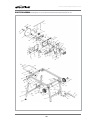
1
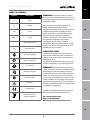
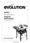
EN
DE
RAGE 5
Original Instructions
ES
FR
IT
NL
Written in UK English
V1
Date Published: 15 / 08 / 2013
www.evolutionpowertools.com
TABLE OF CONTENTS
English
Page 02
Deutsch
Seite 32
Español
Página 68
Français
Page 104
Italiano
Pagina 140
Nederlands
Pagina 176
Important Information
Page 03
Guarantee
Page 03
Specification
Page 04
Labels & Symbols
Page 05
General Safety Rules
Page 06
Safety Precautions for All Saws
Page 06
Additional Specific Safety Rules
Page 08
Machine Overview
Page 10
Service Parts Diagram
Page 11
Assembly
Page 13
Operation
Page 16
Maintenance
Page 28
Environmental Protection
Page 29
Trouble Shooting Guide
Page 29
EC - Declaration of Conformity
Page 30
2
www.evolutionpowertools.com
EN
IMPORTANT
Please read these operating and safety
instructions carefully and completely. For
your own safety, if you are uncertain about
any aspect of using this equipment please
access the relevant Technical Helpline,
the number of which can be found on
the Evolution Power Tools website. We
operate several Helplines throughout our
worldwide organization, but Technical
help is also available from your supplier.
WEB
www.evolutionpowertools.com/register
EMAIL
[email protected]
Congratulations on your purchase
of an Evolution Power Tools Machine.
Please complete your product registration
‘online’ as explained in the A4 online
guarantee registration leaflet included
with this machine. You can also scan the
QR code found on the A4 leaflet with
a Smart Phone. This will enable you to
validate your machine’s guarantee period
via Evolutions website by entering your
details and thus ensure prompt service
if ever needed. We sincerely thank you
for selecting a product from Evolution
Power Tools.
EVOLUTION LIMITED GUARANTEE
Evolution Power Tools reserves the right
to make improvements and modifications
to the product design without prior notice.
Please refer to the guarantee registration
leaflet and/or the packaging for details of
the terms and conditions of the guarantee.
Evolution Power Tools will, within the
guarantee period, and from the original date of
purchase, repair or replace any goods found to
be defective in materials or workmanship. This
guarantee is void if the tool being returned
has been used beyond the recommendations
in the Instruction Manual or if the machine
has been damaged by accident, neglect, or
improper service.
This guarantee does not apply to machines
and / or components which have been altered,
changed, or modified in any way, or subjected
to use beyond recommended capacities
and specifications. Electrical components
are subject to respective manufacturers’
warranties. All goods returned defective shall
be returned prepaid freight to Evolution Power
Tools. Evolution Power Tools reserves the right
to optionally repair or replace it with the same
or equivalent item.
There is no warranty – written or verbal – for
consumable accessories such as (following list
not exhaustive) blades, cutters, drills, chisels
or paddles etc. In no event shall Evolution
Power Tools be liable for loss or damage
resulting directly or indirectly from the use
of our merchandise or from any other cause.
Evolution Power Tools is not liable for any
costs incurred on such goods or consequential
damages. No officer, employee or agent of
Evolution Power Tools is authorized to make
oral representations of fitness or to waive any
of the foregoing terms of sale and none shall
be binding on Evolution Power Tools.
Questions relating to this limited guarantee
should be directed to the company’s head
office, or call the appropriate Helpline number.
DE
ES
FR
IT
NL
3
www.evolutionpowertools.com
SPECIFICATIONS
MACHINE
Metric
Imperial
Motor UK/EU: 230-240V ~ 50Hz (S6 40%)
1800W
8A
Motor UK: 110V ~ 50Hz
1600W
15A
Table Dimensions
656 x 1260mm
26 x 49-5/8”
Speed (No Load)
2500min-1
2500rpm
CUTTING CAPACITIES
Mild Steel Plate – Max Thickness
6mm
1/4”
0
80mm
3-1/8˝
Wood - Maximum Depth Of Cut At 450
55mm
2-1/8˝
38kg
84lb
1.8mm
.070˝
Diameter
255mm
10˝
Bore
25.4mm
1˝
Kerf
2mm
.078˝
28
28
2750min-1
2750rpm
Wood - Maximum Depth Of Cut At 90
Weight
Riving Knife Thickness
BLADE
Teeth
Max Speed
Noise & vibration Data
Sound Pressure L A
230-240V - 91.9dB(A)
110V - 90.2dB(A)
P
Sound Power Level L A
230-240V - 104.5dB(A)
110V - 104.2dB(A)
W
Uncertainty K
3dB(A)
4
www.evolutionpowertools.com
EN
LABELS & SYMBOLS
Symbol
Description
V
Volts
A
Amperes
Hz
Hertz
Min-1
Speed
~
Alternating current
no
No load speed
WARNING: Do not operate the saw if any
warning and/or instruction labels are missing
or damaged. Contact evolution power tools for
replacement labels.
Only use genuine Evolution replacement
blades. Unauthorized blades may be
dangerous! Keep the blades securely fastened.
Check for debris before installing any new
blades and do not use dull or broken blades.
Check the blades regularly for condition
and wear. Damaged or worn blades should
be replaced immediately. Loose fitting
or damaged guards must be replaced
immediately. Beware of ejecting chips as they
may be HOT. Always make provisions for safe
handling of excess material.
Vibration level
Wear safety goggles
Wear ear protection
Do not touch
Wear dust protection
Read Instructions
Warning
ES
The declared vibration total value has been
measured in accordance with a standard test
method and may be used for comparing one
tool with another.
The declared vibration total value may also be
used in a preliminary assessment of exposure.
WARNING: The vibration emission during
actual use of the power tool can differ from the
declared total value depending on the ways
in which the tool is used. The need to identify
safety measures and to protect the operator
are based on an estimation of exposure in the
actual conditions of use (taking account of all
parts of the operating cycle, such as the times
the tool is switched off, when it is running idle,
in addition to trigger time).
CE certification
To obtain an additional copy of your manual,
please contact Evolution Power Tools at:
Waste electrical and
electronic equipment
DE
FR
IT
UK: +44 (0)114 251 1022
USA: 1-866-EVO-TOOL
WEB: www.evolutionpowertools.com
NL
5
www.evolutionpowertools.com
IMPORTANT SAFETY INSTRUCTIONS
To reduce the risk of electric shock, this
equipment is fitted with an approved cord and
plug for its intended country of use. Do not
change the cord or plug in any way.
GENERAL SAFETY RULES
Read and understand all instructions before
operating this product. Failure to follow all
instructions listed below may result in electric
shock, fire and / or serious personal injury.
SAVE THESE INSTRUCTIONS
FOR FUTURE REFERENCE.
WARNING: When using electric tools basic
safety precautions should always be followed
to reduce the risk of fire, electric shock and
personal injury including the following:
Read all these instructions before
attempting to operate this product and save
these instructions.
The term “power tool” in the warnings refers to
your mains-operated (corded) power tool or
battery-operated (cordless) power tool.
SAFETY INSTRUCTIONS FOR ALL SAWS
WARNING: Read all instructions. Failure
to follow all instructions listed below may
result in electric shock, fire and/or serious
injury.
SAVE THESE INSTRUCTIONS
1) Work area safety
a) Keep work area clean and well lit.
Cluttered and dark areas invite accidents.
b) Do not operate power tools in explosive
atmospheres, such as in the presence of
flammable liquids, gases or dust. Power
tools create sparks which may ignite the dust
or fumes.
6
c) Keep children and bystanders away
while operating a power tool.
Distractions can cause you to lose control.
2) Electrical safety
a) Power tool plugs must match the outlet.
Never modify the plug in any way. Do not use
any adapter plugs with earthed (grounded)
power tools.
Unmodified plugs and matching outlets will
reduce risk of electric shock.
b) Avoid body contact with earthed
or grounded surfaces such as pipes,
radiators, ranges and refrigerators. There is
an increased risk of electric shock if your body
is earthed or grounded.
c) Do not expose power tools to rain or wet
conditions. Water entering a power tool will
increase the risk of electric shock.
d) Do not abuse the cord. Never use the
cord for carrying, pulling or unplugging
the power tool. Keep cord away from heat,
oil, sharp edges or moving parts. Damaged or
entangled cords increase the risk of electric shock.
e) When operating a power tool outdoors,
use an extension cord suitable for outdoor
use. Use of a cord suitable for outdoor use
reduces the risk of electric shock.
f) If operating a power tool in a damp
location is unavoidable, use a residual
current device (RCD) protected supply.
Use of an RCD reduces the risk of electric shock.
3) Personal safety
a) Stay alert, watch what you are doing
and use common sense when operating
a power tool. Do not use a power tool
while you are tired or under the influence of
drugs, alcohol or medication. A moment of
inattention while operating power tools may
result in serious personal injury.
b) Use safety equipment. Always wear
eye protection. Safety equipment such as
www.evolutionpowertools.com
EN
dust mask, non-skid safety shoes, hard hat,
or hearing protection used for appropriate
conditions will reduce personal injuries.
c) Avoid accidental starting. Ensure
the switch is in the off-position before
plugging in. Carrying power tools with your
finger on the switch or plugging in power tools
that have the switch on invites accidents.
d) Remove any adjusting key or spanner
before turning the power tool on. A spanner
or a key left attached to a rotating part of the
power tool may result in personal injury.
e) Do not overreach. Keep proper footing and
balance at all times. This enables better control of
the power tool in unexpected situations.
f) Dress properly. Do not wear loose
clothing or jewellery. Keep your hair, clothing
and gloves away from moving parts.
Loose clothes, jewellery or long hair can be
caught in moving parts.
g) If devices are provided for the connection
of dust extraction and collection facilities,
ensure these are connected and properly
used. Use of these devices can reduce dust
related hazards.
4) Power tool use and care
a) Do not force the power tool. Use the
correct power tool for your application.
The correct power tool will do the job better
and safer when used at the rate for which it
was designed.
b) Do not use the power tool if the switch
does not turn it on and off. Any power tool
that cannot be controlled with the switch is
dangerous and must be repaired.
c) Disconnect the plug from the power source
before making any adjustments, changing
accessories, or storing power tools. Such
preventive safety measures reduce the risk of
starting the power tool accidentally.
d) Store idle power tools out of the reach
of children and do not allow persons
unfamiliar with the power tool or these
instructions to operate the power tool.
Power tools are dangerous in the hands of
untrained users.
e) Maintain power tools. Check for
misalignment or binding of moving parts,
breakage of parts and any other condition
that may affect the power tools operation.
If damaged, have the power tool repaired
before use. Many accidents are caused by
poorly maintained power tools.
f) Keep cutting tools sharp and clean.
Properly maintained cutting tools with sharp
cutting edges are less likely to bind and are
easier to control.
g) Use the power tool, accessories and
tool bits etc., in accordance with these
instructions and in the manner intended
for the particular type of power tool,
taking into account the working conditions
and the work to be performed. Use of
the power tool for operations different from
intended could result in a hazardous situation.
5) Service
Have your power tool serviced by a
qualified repair person using only genuine
replacement parts. This will ensure that the
safety of the power tool is properly maintained.
DE
ES
FR
HEALTH ADVICE
Warning: When drilling, sanding, sawing
or grinding, dust particles will be produced.
In some instances, depending on the materials
you are working with, this dust can be
particularly harmful to you (e.g. lead from
old gloss paint).You are advised to consider
the risks associated with the materials you
are working with and to reduce the risk of
exposure.
IT
You should:
• Work in a well-ventilated area.
• Work with approved safety equipment, such
as dust masks that are specially designed to
filter microscopic particles.
NL
7
www.evolutionpowertools.com
SAFETY PRECAUTIONS FOR TABLE SAWS
a) Do not use saw blades which are
damaged or deformed.
b) Replace the table insert/access plate if
worn.
c) Use only blades as recommended in this
manual, which conform to EN 847-1. When
changing a saw blade ensure that the width of the
groove (kerf) cut by the blade is slightly greater
than the thickness of the riving knife. Also the
thickness of the blade body must not be greater
than the thickness of the riving knife.
d) Take care that the selection of the saw
blade is suitable for the material to be cut.
e) Wear suitable personal protective
equipment when necessary. This could include:
Hearing protection to reduce the risk of
induced hearing loss.
Respiratory protection to reduce the risk of
inhalation of harmful dust.
Wearing gloves when handling saw blades or
rough material.
f) Saw blades should be carried in a holder
whenever practicable.
g) Never perform any operation freehand.
This means using only your hands to
support or guide the workpiece. Always use
either the fence or mitre gauge to position and
guide the work.
Warning: Freehand cutting is a major
cause of accidents.
h) Never attempt to free a stalled blade
without first turning the saw off. Turn the
power off immediately to prevent damage
to the motor.
i) Provide adequate support for long or
wide workpieces.
j) Avoid awkward operations and hand
positions where a slip could cause your
hand to move into the blade.
k) Do not operate the appliance with a
damaged cord or plug. If the supply cord
is damaged, it must be replaced by the
8
manufacturer or its service agent or
a similarly qualified person in order
to avoid a hazard.
ADDITIONAL SPECIFIC SAFETY
RULES FOR TABLE SAWS
Warning: Before using your table saw it is
important that you read and understand these
safety rules. Failure to follow these rules could result
in serious injury to the operator or damage to the
table saw.
a) Always use the blade guard. The blade
guard must always be used in every operation.
b) Hold the work firmly. Against the mitre
gauge or rip fence.
c) Always use a push stick. Especially when
rip cutting narrow stock.
d) Keep guards in place and in working
order. Always ensure that the riving knife is
fitted and correctly adjusted. Inspect the riving
knife regularly and replace it if it is worn. Use
only a genuine Evolution riving knife as this is a
dedicated component for this machine.
e) Remove adjusting keys and wrenches.
Form the habit of checking to see that keys
and adjusting wrenches are removed from the
machine before turning it on.
f) Do not use in dangerous environment.
Do not use power tools in damp or wet
locations, or expose them to rain. Keep work
area well lit. Keep the area well ventilated.
g) Keep children away. All children and
visitors should be kept at a safe distance from
the work area.
h) Do not use High Speed Steel (HSS)
blades. Ensure that the correct blade is selected
for the material being cut.
i) The push stick or push block should
always be stored with the machine when
not in use.
j) Connect the saw to a dust collection
device when sawing wood. The operator
should be informed of the factors that influence
exposure to dust e.g. type of material being cut
www.evolutionpowertools.com
EN
and the importance of local extraction (capture
or source) and the proper adjustment hoods/
baffles/chutes.
k) Use proper extension cord. Make sure any
extension cord is in good condition. When using
an extension cord, be sure to use one heavy
enough to carry the current your machine will
draw. An undersized cord will cause a drop
in line voltage resulting in loss of power and
possible overheating.
l) Always use safety glasses. Also use a face
or dust mask if the cutting operation is dusty.
Everyday eyeglasses only have impact resistant
lenses, they are NOT safety glasses.
m) Maintain tools with care. Keep tools sharp
and clean for best and safest performance.
Follow instructions for lubricating and changing
accessories.
n) Disconnect from the power supply before
servicing, cleaning or and when changing
accessories, such as blades.
o) Use recommended accessories. Only use
genuine Evolution accessories.
p) Check for damaged parts. Before further
use of the tool, a guard or other part that
is damaged should be carefully checked to
determine that it will operate properly and
perform its intended function - check for
alignment of moving parts, binding of moving
parts, breakage of parts, mounting, and any
other conditions that may affect its operation.
A guard or other part that is damaged should
be properly repaired or replaced.
q) Keep hands out of the path of the saw
blade.
r) Never reach around the saw blade.
s) Turn off machine and wait for saw
blade to stop before making any fence
adjustments.
t) Never pull or carry the tool by the power
cord. Carrying or pulling the tool by the power
cord could cause damage to the insulation or
the wire connections resulting in the possibility
of electric shock or fire.
u) When transporting the machine use a
transportation device.
Never use the guards for handling or
transportation.
v) During transportation the upper part of
the saw blade must be lowered fully and
covered by the guard.
w) All operators using this machine must
read the instructions and familiarize
themselves with the machines workings.
x) Never leave the saw running and
unattended. Do not leave the saw until the
saw has been switched OFF, and the blade
has come to a complete halt.
DE
ITEMS SUPPLIED
Description
Quantity
Blade Changing Tools
3
Mitre Gauge
Assembly
1
Hold Down Clamp
Assembly
1
ES
FR
Adjustable Rip Fence
2
Push Stick
1
Blade Guard
1
Instruction Manual
1
TCT Multi Purpose
Blade (Fitted)
1
Riving Knife
1
IT
NL
9
www.evolutionpowertools.com
MACHINE OVERVIEW OF EVOLUTION 255mm (10˝) RAGE TABLE SAW
9
4
5
3
11
6
2
12
13
10
7
1
8
14
14
Know your parts
1. On/Off Switch
2.Sliding Carriage
3. Mitre Gauge
4. Blade Guard
5. Rip Fence
6. Rip Fence Locking Handle
7. Transportation Handle
8. Transportation Wheels
9. Hold Down Clamp
10. Dual Function Adjustment Handle
11. RH Table Extension
12. RH Table Locking Lever
13. Push Stick
14. Rear Cantilever Braces
10
www.evolutionpowertools.com
EN
PARTS DIAGRAM Parts Diagrams can also be downloaded from www.evolutionpowertools.com
DE
ES
FR
IT
NL
11
www.evolutionpowertools.com
PARTS DIAGRAM Parts Diagrams can also be downloaded from www.evolutionpowertools.com
12
www.evolutionpowertools.com
EN
ASSEMBLY & OPERATION
Note: Some minor assembly is required to prepare this machine
for use. Please refer to the Service Parts Diagram.
Some of the following tasks can be carried out with the machine
still in its packaging if desired.
WARNING: Do not connect this machine to a power supply until
assembly has been completed, and a thorough safety check of the
machine and all of its systems has been carried out.
DE
Check that all the contents (as listed in this Instruction Manual)
are present.
Follow these instructions if the leg set and plastic lower safety
guard are fastened to the machine.
• Read and understand these instructions.
• Visually check the inside of the machine body to locate any
•
•
•
•
•
polystyrene transit packing. This polystyrene is present to
provide protection for the machines internal components during shipping. It is not required operationally and must be removed before the machine can be used.
Remove 6 of the 8 cross-head screws which fasten the lower
plastic safety guard to the body of the machine.
The 2 screws positioned underneath the sliding
transportation handle can be left in place.
Carefully ease the guard upwards to gain access to the inside
of the machine.
Reach inside and remove any transit packing present.
Replace the lower plastic safety guard and replace the 6
cross-head screws.
Remove the machine from the packaging.
ES
FR
WARNING: This machine is heavy. Enlist competent help
when removing this machine from its packaging.
1. Deploying the Legs
The legs are stored underneath the machines main body.
• Release the retaining hook found to the front of the machine.
• Swing the legs outwards
• Secure the legs by hooking the safety hook over the
IT
protruding metal screw.
• Unhook and deploy the 2 rear cantilever braces and
re-hook them into their operational position. (Fig. 1)
Note: The cantilever braces, and one of the main legs have
an adjustable foot which can be screwed in or out to obtain
maximum stability for the machine, particularly on uneven
surfaces.
13
FIG. 1
NL
www.evolutionpowertools.com
ASSEMBLY & OPERATION
2. Fitting the Riving Knife
WARNING: Ensure that this procedure is only carried out with
the machine disconnected from the mains supply.
The Riving Knife is a very important component, and must be
fitted correctly. The Riving Knife has two functions:
• It prevents the workpiece from binding as it passes through
the blade.
• It provides a suitable connection point for the blade guard.
FIG. 2
To fit the Riving Knife:
Remove the table insert by rotating its fixing screw (Fig 2)
approx 1/4 turn.Lift & slide the table insert from the table.
Raise the blade to its highest position. (see Operations 2)
Loosen the Riving Knife fixing bolt by several turns.
Slide the Riving Knife (it is slotted for convenience) between
the fixing plate and mounting block. (Fig. 3) Ensure that the
mounting blocks projecting lugs engage with the slot in the
Riving Knife.
Adjust the Riving Knife so that it is between 3 - 5mm from the
saw blade. (Fig. 4)
When correct alignment is achieved tighten the fixing bolt.
Check the saw blade rotates freely and teeth are within
3- 5mm of the Riving Knife.
Re-install the Table insert.
•
•
•
•
•
•
•
FIG. 3
3-5mm
•
3. The Rip Fence
This machine has a two (2) piece Rip Fence.
The Rip Fence Face Plate must be attached to the Rip Fence.
FIG. 4
• Loosen the two thumb nuts to the RH side of the Rip Fence.
• Slide the Rip Fence Face Plate onto the Rip Fence. (Fig. 5)
• Tighten the two thumb nuts.
FIG. 5
14
www.evolutionpowertools.com
EN
ASSEMBLY & OPERATION
To attach the assembled Rip Fence to the machine:
Hook the rear of the Rip Fence Guide over the rear Rip
Fence Rail. (Fig. 6A)
With the handle in its upper position, locate the front of the
Rip Fence over the front Rip Fence Rail. (Fig. 6B) Push the
handle down to lock the Rip Fence in place.
•
•
4. The Mitre Gauge
The Mitre Gauge has an adjustable Face Plate.
Insert the Hold Down Clamp Pillar into the socket in the Mitre
Gauges main body.
Ensure that the hole in the Pillar lines up with the hole in the
vertical face of the Mitre Gauge. (Fig. 7)
Attach the Face Plate to the Mitre Gauge by sliding its
attachment screw through the Mitre Gauges vertical face and
the hole in the Pillar.
Attach the locking thumb nut to the attachment screw.
The Mitre Gauge is used on the LH side of the table and runs
in an inverted T slot in the table top.
•
•
•
DE
FIG. 6A
•
•
•
5. Blade Guard
A fully side shielded blade guard is provided with this machine.
This guard must be attached to the blade riving knife, and the
machine should never be used without this guard in position.
ES
FIG. 6B
Note: The single hole near the top edge of the riving knife
serves as the attachment point for the Blade Guard.
FR
WARNING: The machine must be disconnected from the
mains supply when installing the blade guard.
To attach the Blade Guard:
Raise the blade to its full height (Refer to Operations 2) to
fully reveal the riving knife.
Remove the locating bolt, washer and wing nut from the
Blade Guard assembly.
Offer the Blade Guard up and onto the riving knife ensuring
that the hole through the Blade Guard assembly lines up with
the hole in the riving knife. (Fig. 8)
The locating bolt should be inserted through the Blade Guard
assembly and the hole in the riving knife and the washer and
wing nut fitted to one side. The Blade Guard must be able
to move easily and smoothly on the riving knife, so do not
over-tighten this wing nut.
•
•
FIG. 7
•
IT
•
FIG. 8
NL
15
www.evolutionpowertools.com
ASSEMBLY & OPERATION
• Check the operation of the blade guard. Ensure that it is
•
•
•
FIG. 9
working efficiently and covers the blade entirely at the sides
as well as the crown.
Lower the blade a little and recheck that the blade
guard operation.
When satisfied that the blade guard works throughout the
blades height adjustment range, check that the guard works
equally well with the blade set to a bevel angle. (Fig. 9)
Check that when the blade is fully lowered, the blade guard
and side covers are in contact with the table top.
6. Transporting your Table Saw
WARNING: This machine is heavy. Enlist competent help
whenever you have to transport this machine.
FIG. 10
1.Ensure that the machine is disconnected from the power
supply and that the power cord is securely stored on the machine.
2.Lower the blade completely into the machine so that the
bottom of the blade guard lies flat on the machine table.
1.Remove and store safely any accessories e.g. mitre gauge, push
stick, rip fence etc that are not secured to the machine.
2.Release the legs and fold them and the cantilever braces
up into the base, securing them with the locking hooks.
Competent help is useful when attempting this and when
lowering the saw to the ground.
3.Pull out the transportation handle, located at the opposite
side of the saw to the transportation wheels.
4.Lift the handle and allow the machines integral
transportation wheels to touch the ground. (Fig.10)
5.Wheel the machine to its new location.
6.Re-commission the machine and reattach the accessories.
OPERATIONS
CONTROLS
1. ON/OFF Safety Switch
WARNING: Before operating the ON/OFF switch make sure that
the blade guard is correctly installed and operating properly.
To start the machine, press the tab on LH side of the red safety
button and lift it and the switch cover plate upwards to reveal the
on and off buttons. Push the ‘ON’ button to start the machine and
the ‘OFF’ button to stop the machine. (Fig.11)
FIG. 11
WARNING: Never start the machine until all safety checks
and procedures have been carried out.
16
www.evolutionpowertools.com
EN
ASSEMBLY & OPERATION
2. Raising/Lowering the blade
WARNING: Only make adjustments to the machine when the
machine is switched OFF and the blade is stationary.
Note: This machine is equipped with a dual function folding
handle hand-wheel. In its ‘normal’ (outer) position the handwheel is used to raise or lower the blade. When the hand-wheel
is pushed in against its bias spring it engages with the curved
toothed rack incorporated in the machines main body. This
allows the hand-wheel to be used to adjust the tilt/bevel angle
of the blade.
DE
FIG. 12
To raise or lower the blade:
Ensure that the hand-wheel is in its ‘normal’ position.
Turn clockwise to lower the blade. (Fig. 12)
Turn counter clockwise to raise the blade.
•
•
•
ES
3. Tilting the Blade
The blade can be tilted up to 450 to the left.
Loosen the tilt locking screw (Fig. 13) by turning the tilt
locking lever.
Push the hand-wheel in against its bias spring until it
engages the tilt rack.
Use the hand-wheel to set the required angle. An angle
gauge to aid setting can be found behind the hand-wheel
Tighten the tilt locking screw when the required angle is
achieved.
Allow the hand-wheel to return to its ‘normal’ position.
•
•
FIG. 13
•
•
FR
•
Note: The tilt locking lever is sprung loaded and adjustable.
This enables the lever to be repositioned on the locking screw.
• Pull out the lever and move to the desired position.
• Release the lever and allow the spring to re-seat the lever.
Repositioning may be necessary to avoid fouling the machines
hand-wheel when the blade is tilted.
IT
NL
17
www.evolutionpowertools.com
ASSEMBLY & OPERATION
4. Rip Fence Guide
This machine is fitted with a two piece Rip Fence. We recommend
that the Rip Fence is normally used in conjunction with its
adjustable Face piece.
The Rip Fence should be positioned to the RH side of the blade
and is locked in position by using the locking lever. Push down to
lock, and pull up to unlock.
FIG. 14
FIG. 15
When repositioning the Rip Fence use the mid-point of the fence
to push or pull the fence to the desired position.
(Fig. 14) Using the mid-point aids accuracy and speed of setting.
The clamping system is designed to correctly align the fence
when the locking lever is pushed down.
Check alignment by sighting either side of the fence with any of
the ‘ lines’ that run across the table.
If misalignment is suspected, the pressure being applied by the
Rip Fence locking lever could be at fault.
To adjust the locking lever pressure:
Ensure that the locking lever is in the unlocked position.
Turn the clamp pressure adjustment nut (Fig. 15) one flat
either clockwise or counter-clockwise.
Recheck Rip Fence operation and alignment.
Continue nut adjustment until the Rip Fence operation is
satisfactory and alignment and clamping is always achieved
wherever the fence is positioned.
•
•
•
•
Note: The Rip Fence guide incorporates a ‘transparent window’
with a datum line to aid reading the measurement scale found
on the fence rail. (Fig. 16)
FIG. 16
FIG. 17
Forwards and backwards adjustment of the Rip Fence Face is
possible. Loosen the two thumb nuts and slide the aluminium
Fence Face extrusion to the desired position. Tighten the thumb
nuts securely.
Note: We recommend that normally the Rip Fence Face be
adjusted so that the rear of the Fence Face is level with the rear
of the blade where it emerges from the table. This will provide
clearance for the workpiece as it passes the blade.
The Rip Fence Face has a ‘Hi’ and ‘Lo’ position. The ‘Lo’ position
can be very useful when cutting thin sheet material as it gives
the operator a better view of the workpiece as it passes through
the blade. (Fig.17)
18
www.evolutionpowertools.com
EN
ASSEMBLY & OPERATION
To reposition the Rip Fence Face:
Loosen the two thumb nuts to the RH side of the Rip Fence.
Slide out the Rip Fence Face extrusion.
Re-attach the Rip Fence Face in the ‘Lo’ position.
Adjust to suit and tighten the two thumb nuts.
Return to the normal ‘Hi’ position when cutting has been
completed.
•
•
•
•
•
DE
5. Mitre Gauge
The mitre gauge is used on the LH side of the table and runs in
an inverted T slot in the sliding carriage table top.
Turn the vertical handle counter-clockwise to unlock the mitre
gauge, and adjust to the required mitre angle. Turn the handle
clockwise to lock the mitre gauge at the chosen angle.
Note: We recommend that the Mitre Gauge Slide Locking screw
(Fig. 18) be removed and stored safely off the machine for future
use when the Mitre Gauge is being used with the sliding carriage
in the ‘locked’ position.
We further recommend that the Hold Down Clamp be removed
from the Mitre Gauge and stored safely when the machine is being
used with the sliding carriage in the ‘locked’ position.
FIG. 18
ES
FIG. 19
Note: The extruded aluminium face plate of the mitre gauge
should be adjusted so that it is close to, but does not foul the
blade guard. Adjust by loosening the finger nut and sliding the
faceplate to the required position. Securely tighten the thumb
nut. (Fig. 19)
FR
The Mitre Gauge can be set at any angle between 600 Left and
600 Right.
Fast index positions are incorporated into the design for 900,
450 L and 450R.
To use the Fast Index facility:
900 - Ensure that the ‘stop plate’ is in the down position and the
900 index screw is resting against its RH side. (Fig. 20)
450 L - Open the ‘stop plate’ by pivoting it upwards. Loosen the
vertical locking handle and rotate the Mitre Gauge so that the 450
L index screw just passes through the ‘stop plate’. Close the ‘stop
plate’ and bring the 450 L index screw to rest against the RH side of
the closed ‘stop plate’. Tighten the handle
450 R - Open the ‘stop plate’ by pivoting it upwards. Loosen the
vertical locking handle and rotate the Mitre Gauge so that the
900 index screw passes through the ‘stop plate’.
Close the ‘stop plate’ and bring the 450 R index screw to rest
against the RH side of the ‘stop plate’.
FIG. 20
•
•
IT
•
•
NL
19
www.evolutionpowertools.com
ASSEMBLY & OPERATION
Note: Each of the fast index screws has been factory set for
angular accuracy. All the index screws can be adjusted if
necessary.
The ‘stop plate’ should rotate easily. It is important that the
punched swage on the plate (Fig. 21) which prevents it from
being over-rotated and potentially fouling the ‘T’ slot be
checked and adjusted.
FIG. 21
To check and adjust the ‘stop plate’:
Rotate the ‘stop plate’ forward.
Visually check that the punched swage is resting upon the
plastic index pointer preventing over-rotation.
If necessary adjust the ‘stop plate’ mounting screw so that
plate moves easily and the swage always rests upon but
cannot slide past the plastic index pointer. (Fig. 22)
•
•
•
Index Screw Checking and Adjustment
To check the accuracy of the angular settings the operator will
require an Engineers Square and a 450 Square. (Not supplied)
FIG. 22
WARNING: Only carry out these procedures with the machine
disconnected from the mains supply.
To Check 900 Setting (Fig. 23)
Raise the blade to its full height.
Place the engineers square on the machine table with one
leg resting accurately against the saw blades body.
Check that the Mitre Gauge is set at 900.
Slide the Mitre Gauge into its ‘T’ slot and slide it up to the
other leg of the engineers square.
The Mitre Gauges Face Plate should index precisely with the
engineers square.
•
•
•
•
•
FIG. 23
(Blade guard removed for clarity)
If adjustment is required:
Loosen the index screws locking nut. (Fig. 24)
Turn the index screw clockwise or counter-clockwise until
precise alignment with the engineers square is achieved.
Re-tighten the locking nut.
•
•
•
FIG. 24
20
www.evolutionpowertools.com
EN
ASSEMBLY & OPERATION
To Check 450 Settings
Raise the blade to its full height.
Place the 450 square on the machine table with one face
resting accurately against the saw blades body. (Fig. 25)
Check that the Mitre Gauge is set at one of the 450 settings.
Slide the Mitre Gauge into its ‘T’ slot and slide it up to the
edge of the 450 square.
The Mitre Gauge Face Plate should index precisely with the
edge of the 450 square.
•
•
•
•
•
If adjustment is required follow the instructions as for the
setting of the 900 setting.
DE
FIG. 25
(Blade guard removed for clarity)
6. Multi-Function Table Top
This Table Saw is equipped with a versatile table top capable
of various adjustments which are designed to aid operator
efficiency and safety.
ES
Table extensions
The table can be extended to the RH and to the LH side, to
provide extra workpiece support when necessary. Both sides of
the table can be extended at the same time, or just one side at a
time as required operationally.
FIG. 26
To extend the table to the RH side:
Pull up the table extension locking lever found just above the
machines ON/OFF switch. (Fig. 26)
Deploy the table extension to give the required workpiece
support.
Push the locking lever down to lock the table in the required
position.
Re-attach and/or adjust the Rip Fence as required.
When cutting is completed return the table to its original
setting.
•
•
FR
•
•
•
Note: The Fence Rail will ‘travel’ with the RH table extension
when it is deployed. A window with datum index line is built
into the front edge of the table to aid setting. (Fig. 27)
To extend the table to the LH side:
Loosen the two locking knobs (one to the front and one
to the rear of the machine) underneath the LH side of the
machines table. (Fig. 28)
Deploy the table extension.
Tighten the locking knobs.
When cutting is completed return the table to its original
setting.
FIG. 27
IT
•
•
•
•
FIG. 28
NL
21
www.evolutionpowertools.com
ASSEMBLY & OPERATION
FIG. 29
Sliding Carriage System
This machine is fitted with a Sliding Carriage to the LH side of
the blade. This facility can be particularly useful when crosscutting small section material such as metal box-section or
extrusions etc.
The sliding carriage should always be used with the Mitre
Gauge locked to it in the desired position.
Material can be clamped to the Sliding Carriage by using
the Mitre Gauge with its Hold Down Clamp, thus enhancing
operator control and safety.
The sliding carriage system can also be very useful (when used
in conjunction with a locked on Mitre Gauge) for repetitive
cross-cutting.
To Release the Sliding Carriage
WARNING: The machine must be switched off, the blade
stationary, and the switch cover plate in the closed (safe)
position whenever adjustments etc are being made to the
machine or the workpiece.
The Sliding Carriage Locking Latch is located to the rear of the
machine table and slightly to the LH side of the blade. (Fig. 29)
• Slide the latch to the right to unlock the carriage and pull the
carriage forward.
• When operations are completed, return the carriage to its
•
original position and slide the locking latch to the left to lock
the carriage.
Check that the carriage is locked in its ‘locked’ position.
22
www.evolutionpowertools.com
EN
ASSEMBLY & OPERATION
BASIC TABLE SAW OPERATIONS
Multi-purpose blade
The Rage 5 comes fitted with a multi-purpose TCT blade which
is capable of cutting many materials. We recommend that a
workshop dust extraction system is always attached to the
dust extraction port (Fig. 30) when cutting wood or wooden
products to prevent any possible build up of sawdust in the
lower blade guard.
When changing the blade (See Maintenance) the operator
should visually check for any dust build up in the lower blade
guard. With the blade removed any residual dust can be
sucked away using a suitable crevice nozzle vacuum extraction
machine. The blade can then be reinstalled.
Metallic materials should not be cut if it is suspected that
there could be residual sawdust in the lower blade guard. The
machine should be disconnected from its power supply and
the table insert removed (refer to ‘Assembly 2 & 4 Figs 2 & 8 )
so that a visual check can be made. (Fig. 31) If there is evidence
of sawdust build-up, remove this sawdust before commencing
metal cutting operations.
DE
FIG. 30
ES
FIG. 31
WARNING: Never attempt freehand cuts on this machine.
Always use the appropriate guide or fence to minimise the
possibility of the blade binding and kickback.
FR
We recommend that the saw blade protrudes through the
material to be cut by approximately 3mm. Adjust the height of
the blade as previously described. This machine is not suitable
for cutting rebates or stopped grooves.
A workshop dust extraction device should be connected to the
extraction port found at the rear of the machine. (Fig. 30)
FIG. 32
1. Crosscutting
Set the mitre gauge to 900 and tighten using the vertical
handle. Position in the ‘T’ slot and adjust the mitre face plate as
previously described. Index the material to be cut against the
mitre gauge faceplate. Switch on the saw and allow to reach full
operating speed before sliding the mitre gauge and workpiece
towards the rear of the table making your cut. (Fig. 32)
2. Mitre crosscutting
Mitre crosscutting is cutting the material at an angle other
than 900. Set the mitre gauge to the desired angle, tighten and
proceed as cross-cutting above. (Fig. 33)
23
IT
FIG. 33
NL
www.evolutionpowertools.com
ASSEMBLY & OPERATION
3. Bevel crosscutting
Bevel crosscutting is the same as crosscutting but with the
blade tilted at an angle. Tilt the blade to the desired angle as
previously described, and ensure that it is locked in place.
Set the mitre gauge to 900 and adjust the faceplate so that it
does not touch or foul the saw blade as it passes. Index the
material against the mitre gauge and make your cut. (Fig. 34)
FIG. 34
4. Compound mitre cutting
Compound mitre cutting is a combination of mitre cutting and
bevel crosscutting.
Adjust the mitre gauge and the blade to the desired angles.
Lock both in place.
Check that the mitre gauge will pass the saw blade without
fouling. Adjust the mitre gauge faceplate if necessary.
Index the material against the mitre gauge and make your cut.
(Fig. 35)
5. Repetitive crosscutting
Repetitive cutting is cutting a number of pieces to the same
length without having to mark out each piece.
FIG. 35
Note: Repetitive cross-cutting is carried out with the mitre
gauge positioned on the LH side of the machine, with the rip
fence on the RH side of the machine.
Caution: The Rip Fence can be used as a length stop only if it
is properly set and adjusted.
To use the Rip Fence as length stop align the back of the
adjustable Fence Face with the back of the saw blade and set at
the required distance from the blade. This will allow clearance
for the material as it passes through the saw blade. (Fig. 36)
FIG. 36
• Check that the Rip Fence is set at the required distance and is
lying parallel to the saw blade.
• Index the material to be cut against the Mitre Gauge and the
Rip Fence Face.
• Hold the material and Mitre Gauge with your left hand.
• Gently push the workpiece through the saw. Use a push stick
in your right hand to guide the workpiece on the RH side of
the blade.
Note: If the Sliding Carriage system is deployed for repetitive crosscutting, the Mitre Gauge must be fastened to the carriage.
We recommend that the mitre gauge be fixed in its dedicated
position to the front of the carriage, where the locking screw will
engage in a hole in the sliding carriage body.
24
www.evolutionpowertools.com
EN
ASSEMBLY & OPERATION
6. Rip cutting
Rip cutting is cutting along the length of a piece of material
rather than across it. Rip cutting should always be done with the
Rip Fence Face set to the desired width and on the RH side of
the machines table.
The mitre gauge is not required for this operation, and should
be stored safely off the machine for future use.
DE
Note: Check that the Rip Fence is locked in position and is
parallel to the saw blade.
Check that the riving knife is properly aligned with the saw blade.
When ripping small section material a push stick should be used
to feed/guide the final 300mm of the material past the blade. A
push stick should always be used when making cuts of less than
300mm.
When ripping long boards or large panels always use a remote
work support or enlist trained competent help.
Feed the workpiece through the saw keeping it indexed against
the rip fence. Use smooth, steady pressure and employ a push
stick if necessary. (Fig. 37)
When the ripping width is greater than 300mm, and with care,
both hands can be used to guide/feed the material through the
saw. The operators left hand will be to the LH side of the saw
blade. The operators right hand will be close to the rip fence on
the RH side of the sawblade. Hands should never be in line with
the blade.
FIG. 37
ES
FR
7. Bevel ripping
When bevel ripping material 150mm or narrower use the rip
fence on the RH side of the blade only.
8. Using the Sliding Carriage System
WARNING: All ‘setting up’ operations should be undertaken
with the machine switched off, the blade stationary, and the
switch cover plate in the closed (safe) position.
IT
Release the carriage by sliding the table latch (located at the
rear of the table and just to the LH of the blade) to the
unlocked position.
• Set the Mitre Gauge to the required angle and lock in place
with the vertical locking handle.
• Slide the Mitre Gauge into the inverted ‘T’ slot and lock in the
required place by tightening the locking knob.
NL
25
www.evolutionpowertools.com
ASSEMBLY & OPERATION
Note: Although the Mitre Gauge can be locked in any desired
position along the ‘T’ slot it does have a dedicated position to
the front of the carriage, where the locking screw will engage in
a hole in the sliding carriage body. (Fig. 38)
• Install the Hold Down Clamp, if required, onto the pillar fitted
•
FIG. 38
•
•
FIG. 39
into the Mitre Gauges main body. (Fig. 39) Tighten in the
required position using the locking screw.
Place the workpiece in the required position and against the
Mitre Gauge Face Plate.
Clamp the workpiece to the Sliding Carriage by adjusting the
Hold Down Clamp for best position and tightening the vertical
locking screw using the large knob. (Fig. 40)
The Mitre Gauge has its own locking screw to lock it to the sliding carriage, but when used with the Hold Down Clamp,
additional security is obtained. Check the integrity of the
installation.
Note: We recommend that the above set up procedure is
completed with the Sliding Carriage pulled out from the
machine table to give the operator the clearance and space to
make any measurements, confirm cutting lines etc.
When satisfied that all adjustments and cutting line positionings
etc are correct, and all adjustment screws are securely
tightened, open the On/Off switch cover plate.
Start the machine and push the Sliding Carriage (by using the
Mitre Gauge) to the rear of the Table to make the cut.
FIG. 40
26
www.evolutionpowertools.com
EN
ASSEMBLY & OPERATION
WARNING: Ensure that the machine is disconnected from
the mains supply before any maintenance tasks or adjustments
are attempted.
CHANGING THE BLADE
Note: We recommend that the operator considers wearing
protective gloves when handling or changing the machines blade.
1.
2.
3.
4.
Disconnect the machine from the power supply
Remove the blade guard. (Refer to Assembly 4)
Remove the table insert by rotating its fixing screw
Approximately 1/4 turn. Lift & slide the insert from the table
& safely store it for future use.
5. Raise the blade to its highest position.
6. Use the two blade changing tools provided. One to hold the
motor arbor, and the other to loosen the arbor nut. (Fig. 41)
7. Remove the nut, outer flange and blade.
8. Fit the new blade. Ensure that the teeth are facing to the
front of the saw, and that the arrow on the blade is in line
with the motor direction.
9. Replace the outer flange and nut and tighten securely with
the spanners provided. Check that both blade flanges are in
contact with the blade.
10.Replace the table insert and its fixing screw. Ensure that the
fixing screw is correctly seated.
11.Replace the blade guard and check all operational functions
of the blade and its guarding system.
12.Only connect the machine to its main supply after a
complete safety check of the machine has been carried out.
Cleaning
After each use the machine should be cleaned. Remove all
sawdust etc from the visible parts of the machine with a vacuum
cleaner. A vacuum cleaner can also be connected to the machine
dust extraction port at the rear of the machine. This should
remove debris from the inside of the machine. Never use solvents
to clean plastic parts, as solvents can damage them. Clean only
with a soft very slightly damp cloth.
DE
FIG. 41
ES
FR
IT
Riving Knife
The riving knife is a very important component and must be
fitted correctly aligned and adjusted. The riving knife prevents the
work from binding as it passes through the blade.
Inspect the riving knife at regular intervals and replace it if it is
worn or damaged.
NL
27
www.evolutionpowertools.com
MAINTENANCE
Note: Use only a genuine Evolution Riving Knife, as this is a
dedicated component for this machine. Non genuine parts could
be dangerous. If in any doubt, please contact the Helpline.
Push Stick
A plastic push stick is provided with the machine and has its
own dedicated storage brackets to the RH side of the machines
main body. (Fig. 42) When not in use store the push stick on
the machine.
FIG. 42
Note: If the push stick becomes damaged it should be replaced. If the
operator makes their own push stick, we recommend that it follows
the same pattern as that supplied. Replacement push sticks are
available from Evolution Power Tools.
Blade Storage
A blade storage facility is available at the RH side of the
machine. (Fig. 43) Undo the centre hand nut and place any
spare blades onto the ø25.4mm metal flange. Secure the blades
with the centre hand nut.
FIG. 43
28
www.evolutionpowertools.com
EN
ENVIRONMENTAL PROTECTION
Waste electrical products should not be disposed of with
household waste. Please recycle where facilities exist. Check
with your Local Authority or retailer for recycling advice.
TROUBLE SHOOTING GUIDE
DE
CONDITION
POSSIBLE CAUSE
ACTION
Machine will not start.
Plug removed from outlet
socket or outlet socket
not switched ‘on’.
Replace plug and/or switch
‘on’ the outlet socket.
Sliding Carriage will
not move.
Sliding Carriage Locking
Latch still fully or
partially engaged.
Ensure that the Carriage
Locking Latch is completely
disengaged by sliding it
fully to the right.
Left Hand Table Extension
will not deploy.
One or both (usually
the rear) of the under-table
locking knobs not
l oosened.
Ensure that both locking
knobs are sufficiently
loosened. Deploy the table
extension and retighten both
under-table locking knobs.
ES
FR
Blade will not rise or fall.
Dual Purpose Rise and
Fall Handle partially engaged
with curved toothed rack.
Ensure that the Handle is
in its outer position. Pull the
Handle out from the machine
slightly to confirm it is deployed
in the outer position.
Blade will not tilt.
Tilt Locking Screw
not loosened.
Loosen the Tilt Locking Screw.
Tilt the blade to the desired
angle and then retighten the
locking screw
Over -tightened rear fixing
screw and wingnut.
Loosen wingnut slightly until
Blade Guard operation is
smooth and satisfactory.
Blade Guard does not
adjust automatically.
IT
NL
29
www.evolutionpowertools.com
EC DECLARATION OF CONFORMITY
In accordance with EN ISO 17050-1:2004
The manufacturer of the product covered by this Declaration is:
Evolution Power Tools, Venture One, Longacre Close, Holbrook Industrial Estate, Sheffield, S20 3FR
The manufacturer hereby declares that the machine as detailed in this declaration fulfils all the
relevant provisions of the Machinery Directive and other appropriate directives as detailed below.
The manufacture further declares that the machine as detailed in this declaration, where
applicable, fulfils the relevant provisions of the Essential Health and Safety requirements.
The Directives covered by this Declaration are as detailed below:
2006/42/EC.
2006/95/EC.
2004/108/EC.
93/68/EC.
2011/65/EU.
2002/96/EC
as amended
by 2003/108/EC.
Machinery Directive.
Low Voltage Equipment Directive.
Electromagnetic Compatibility Directive.
The CE Marking Directive.
The Restriction of the Use of certain Hazardous
Substances in Electrical Equipment (RoHS) Directive
The Waste Electrical and Electronic Equipment (WEEE) Directive.
And is in conformity with the applicable requirements of the following documents:
EN55014-1:2006+A1 • EN55014-2:1997+A1+A2 • EN61000-3-2:2006+A1+A2
EN61000-3-3:2008 • EN61029-1:2009+A11 • EN61029-2-1:2010
Product Details
Description: Evolution Model No:
Brand Name: Voltage: Input: 255mm (10”) TCT Multipurpose TABLE Saw
RAGE52551, RAGE52552, RAGE52552EU
EVOLUTION
110V - 230-240V
50Hz
The technical documentation required to demonstrate that the product meets the requirements
of directive has been compiled and is available for inspection by the relevant enforcement
authorities, and verifies that our technical file contains the documents listed above and that
they are the correct standards for the product as detailed above.
Name and address of technical documentation holder.
Signed:Print: Steven Bulloss: Operations Director
Signed: Print: Lettie Lui: Product Manager
Date: 18/04/2011
30
www.evolutionpowertools.com
EN
NOTES
DE
ES
FR
IT
NL
31
UK
Evolution Power Tools Ltd
Venture One
Longacre Close
Holbrook Industrial Estate
Sheffield
S20 3FR
US
Evolution Power Tools LLC
8363 Research Drive
Davenport
Iowa
52806
+44 (0)114 251 1022
866-EVO-TOOL
エボリューション
パワーツール株式会社
〒544-0031
大阪府大阪市生野区
鶴橋5丁目21-19
JP
EU
Evolution Power Tools Ltd
61 Avenue Lafontaine
33560
Carbon-Blanc
Bordeaux
0120-051-415
+ 33 (0)5 57 30 61 89
Discover Evolution Power Tools
Visit: www.evolutionpowertools.com or download
the QR Reader App on your smart phone and scan
the QR code (Right).