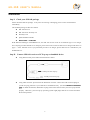
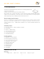
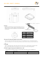
1
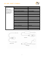
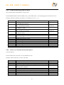
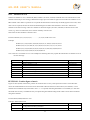
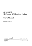
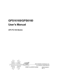
GM-168 USER’S MANUAL
Please read this manual before operating the unit
© ETEK NAVIGATION, INC.
ETEK NAVIGATION, INC.
TEL: 886-2-26860199 FAX: 886-2-26866159
10F, NO. 105, Xicheng Rd., Banqiao City,
Taipei County 220, Taiwan (R.O.C.)
E-Mail: [email protected]
http://www.etek.com.tw
1
Version: 2
GM-168 USER’S MANUAL
Content
Installation..............................................................................................................................................................................................3
Troubleshooting ....................................................................................................................................................................................5
GM-168 Introduction ..........................................................................................................................................................................6
GM-168 Key Feature ...................................................................................................................................................................6
Possible Application .....................................................................................................................................................................6
Familiarize your GM-168 ...................................................................................................................................................................6
Dimensions......................................................................................................................................................................................6
Interface ..........................................................................................................................................................................................7
Water-proof housing with magnet on the bottom................................................................................................................7
LED Light .......................................................................................................................................................................................7
GM-168 Computer/Lap top and handheld device cable ....................................................................................................7
Software Interface ................................................................................................................................................................................9
NMEA Protocol .............................................................................................................................................................................9
NMEA Messages ...........................................................................................................................................................................9
GLL – Geographic Position – Latitude/Longitude ..............................................................................................................9
GGA – Global Positioning System Fix Data ....................................................................................................................... 10
VTG – Course over Ground and Ground Speed............................................................................................................... 10
RMC – Recommended Minimum Specific GNSS Data ...................................................................................................11
GSA – DOP and Active Satellites............................................................................................................................................11
GSV – Satellites in view............................................................................................................................................................ 12
PFST,FOM – Position figure of merit .................................................................................................................................. 12
PFST,PPS – PPS signal............................................................................................................................................................. 13
2
GM-168 USER’S MANUAL
Installation
Step I:Check your GM-168 package
Please check the GM-168 package. If any items are missing or damaging, please contact our distributor
immediately.
The standard package of GM-168 contains:
l
GM -168 Receiver
l
GM -168 Driver & Utility CD
l
Warranty Card
l
Quick Installation Guide
l
RS-232 cable or USB cable
With different brand/type of handheld device, the GM-168 receiver needs to use different type of car charger.
Our company provides all kinds of car chargers, please refer to the section of GM-168 car chargers and cables on
page 7. If the GM-168 receiver you purchased provides a car charger, please make sure it is suitable for your
handheld device.
Step II:Connect GM-168 receiver to PC/Lap top or handheld device
l
Using RS-232 cable: please follow the illustration as below.
To DB-9 port on PC/Lap top
To USB port on PC/Lap Top
l
Using USB connector: please follow the illustration as below. Before the USB connector plugs in
your PC/Lap top, please have your USB Driver Installation ready. (See the USB Driver installation
guide for detail information). Remember to plug in the USB connector after your PC/Lap top started
properly. Otherwise, your PC/Lap top operating system might judge GM-168 as a mouse and affect
the normal operation.
3
GM-168 USER’S MANUAL
To USB port on PC/Lap top
l
Using car charger: Please follows the illustration as below. You have to plug in the connector into Car
Socket in order to have power supply for both GM -168 receiver and handheld device.
To Input/output port of
handheld device
Connect to Car Socket
Step III:Check if the LED is flashing.
Once your PC/Lap top or car charger supplies power, the GM-168 receiver starts to provide the positioning
function. At meantime, the LED will be flashing and it means GM -168 is operating.
4
GM-168 USER’S MANUAL
Troubleshooting
When your GM-168 receiver could not operate, please follow the instruction to do the troubleshooting as below.
1. GM -168 receiver’s LED is not flashing
l
It means GM-168 does not have power supply. Please check if the connector plugs in properly as the
step II.
2. GM -168 receiver’s LED is flashing, but the connection between GM -168 receiver and the E-map can not be
established. Please make sure the settings of COM Port Number and Baud rate are correct.
l
Most of E-map provides scan function to search COM Port. Please scan it for the correct COM Port
number that GM-168 receiver is utilizing.
l
If a RS232 cable is used to connect to PC/Lap top, the COM Port number would COM1 usually.
l
The default Baud rate is 4800.
l
If a USB cable is used to connect to PC/Lap top, please make sure the UBS driver is installed
successfully.
5
GM-168 USER’S MANUAL
GM-168 Introduction
The GM-168 is an outstanding high sensitivity GPS receiver. Its excellent performance easily
conquers the most difficult tasks.
In addition, it provides various functions to meet customers’ demand.
GM -168 employs uNav’s powerful GPS solution. It provides marvelous navigation performance under dynamic
conditions in areas with limited sky view like urban canyons. It also has high sensitivity for weak signal operation
without compromising accuracy. Undoubtedly, GM-168 is the best choice for you.
Market Leading System Performance
Ultra -low, user configurable power management makes GM-168 the lowest power consuming, complete 12-channel
iGPS receiver on the market. Nevertheless, there are no compromises in performance. The iGPS receiver has a
navigation sensitivity as low as –150dBm making it applicable even for extremely demanding applications and
environments.
GM-168 Key Feature
q
Thin module form factor – 45mm(L) x 45mm(W) x 8.5mm(H)
q
Very Fast TTFF
q
Sensitivity: -150dBm (Tracking)
q
iTALK and NMEA0183 protocols
q
Accurate 1PPS timing output
q
iGPS-8MBit Flash Memory
Possible Application
q
Mapping devices for PC & Pocket PC
q
Personal Navigation or touring devices
q
AVL and Location-Based service system
q
Data logging for marine Navigation
q
Support 1pps output for timer
q
Tracking devices/system
q
Mileage Management
q
Fleet Management
q
Car Navigation
Familiarize your GM-168
Dimensions
Length:64 mm
Width:57 mm
Height:16.5 mm
6
Weight:85+/-5 gram
GM-168 USER’S MANUAL
6-pin female connector
Interface
As shown in the illustration on the right, the length of the wire on
GM -168 receiver is 2 meters. There is a 6-pin connector for the
connection to PC/Lap top or handheld device. The ping assignment
is shown below.
2 meters long wire
Ping No.
1
2
3
4
5
6
Function
1 PPS
Tx TTL
DC 5V
RS232 Rx
GND
RS232 Tx
Water-proof housing with magnet on the bottom
There are 4 magnets on the bottom side of GM -168 receiver for adsorbing on your car. The housing of GM-168
receiver has waterproof, it can avoid the water permeates your GM-168 receiver while you adsorb it outside of the
car.
LED Light
There is an LED light near the output cable on the back of GM -168 receiver. When the GM-168 supplied 5V DC
power, the LED will be flashing. It means GM-168 receiver starts to provide the positioning function.
GM-168 Computer/Lap top and handheld device cable
Following table lists each kind of cables for connecting different type of PC/Lap top or handheld device.
Category
RS232 cable
USB cable
Model Number
GM -168-RS232C
GM -168-USBC
Type
RS232 as I/O, power by USB
USB for both I/O and power
7
GM-168 USER’S MANUAL
Handheld device cable
GM -168-CA-ACER N20
GM -168-CA-ACER S60
Remark:
GM -168-CA-ASUS A600
While using the
GM -168-CA-ASUS A620
GM -168 with handheld GM -168-CA-CASIO E115
device, Car charger
GM -168-CA-CASIO E125/EM500
would supply power for GM -168-CA-CASIO E200
both GM-168 and
GM -168-CA-Dell Axim X3
handheld device
GM -168-CA-Dell Axim X5
GM -168-CA-Eten P300
GM -168-CA-I-PAQ 2200i/38xx/39xx
GM -168-CA-I-PAQ 36xx/37xx
GM -168-CA-Mitac Mio 338/528
GM -168-CA-NEC Pocket PC
GM -168-CA-O2 XDA II/T-Mobile MDA
GM -168-CA-O2 XDA/T-Mobile MDA
GM -168-CA-Palm 500/505/T3
GM -168-CA-Palm Vx
GM -168-CA-Siemens LOOX
GM -168-CA-Sony N series
GM -168-CA-Sony T series
GM -168-CA-Toshiba e330/e740
GM -168-CA-Toshiba e400
GM -168-CA-Toshiba e570
GM -168-CA-Toshiba e800
GM -168-CA-Yakumo Delta 300
GM -168-CA-Yakumo Omnikron
ACER N20
ACER S60
ASUS A600
ASUS A620
Casio E115
Casio E125/EM500
Casio E200
Dell Axim X3
Dell Axim X5
Eten P300
I-PAQ 2200i38xx/39xx series
I-PAQ 36xx/37xx series
Mitac Mio 338/528
NEC Pocket PC
O2 XDA II/T-Mobile MDA
O2 XDA/T-Mobile MDA
Palm 500/505/Tungsten T3
Palm Vx
Siemens LOOX
Sony N series
Sony T series
Toshiba e330/e740
Toshiba e400
Toshiba e570
Toshiba e800
Yakumo Delta 300
Yakumo Omnikron
USB cable
RS-232 cable
Car charger
8
GM-168 USER’S MANUAL
Software Interface
NMEA Protocol
GM -168 receiver currently supported 21 NMEA commands and 7 NMEA messages. The NMEA commands include
NMEA, START, STOP, STORE, RESTORE, AUTOSTART, FIXRATE, DATUM, PWRDOWN, PPSMODE,
SURVEYLEN, CABLEDEL, PPSPOS, PULSEPOS, PULSELEN, INITAID, ALTAID, SETLIMIT, SYNCMODE,
SW, and HW. The respond messages include GPGLL, GPGGA, GPVTG, GPRMC, GPGSA, GPGSV, and
“PFST,FOM”.
NMEA Messages
The NMEA -0813 message consists of fields as following:
$GP<message id>,<data field>,<data field>,,, ..*<checksum><CR><LF>
Message starts with ‘$GP’ followed by message id field. Message data fields are separated by commas ( , ) and the
message ends after checksum field and carriage return <CR> and line feed <LF> control characters. Delimiter ‘*’
precedes the checksum field. Note that data fields may be NULL (missing). Null data fields contain no characters but
are still separated by commas, for example:
$GPGGA,134158.48,6016.3072,N,02458.3788,E,1,08,1.2,,,,,,0000*1E
GLL – Geographic Position – Latitude/Longitude
Latitude and Longitude, UTC time of fix and status.
Format: $GPGLL,xxmm.dddd,<N|S>, yyymm.dddd,<E|W>,hhmmss.dd,S,M*hh<CR><LF>
Example: $GPGLL,6016.3073,N,02458.3791,E,134157.48,A,A*26
Parameter
xxmm.dddd
Description
Latitude, xx = degrees, mm = minutes, dddd = decimal part of minutes
<N|S>
Either character N or character S,
N = North, S = South
Longitude, yyy = degrees, mm = minutes
dddd = decimal part of minutes
Either character E or character W,
E = East, W = West
UTC time, hh = hours, mm = minutes, ss = seconds
dd = decimal part of seconds
Status indicator, A = valid, V = invalid
Mode indicator, A = autonomous, N = data not valid
Check sum
yyymm.dddd
<E|W>
hhmmss.dd
S
M
hh
9
Example
60 deg.
16.3073 min.
North
24 deg.
58.3791 min
East
13:41:51.48
Valid
Autonomous
26
GM-168 USER’S MANUAL
GGA – Global Positioning System Fix Data
Time, position and fix related data for a GPS receiver.
Format:$GPGGA,hhmmss.dd,xxmm.dddd,<N|S>,yyymm.dddd,<E|W>,v,ss,d.d,h.h,M,g.g,M,a.a,xxxx*hh<CR><LF>
Example: $GPGGA,134829.48,1126.6639,S,11133.3299,W,1,07,1.0,,,,,,*15
Parameter
hhmmss.dd
xxmm.dddd
<N|S>
yyymm.dddd
<E| W>
v
ss
d.d
h.h
M
g.g
M
a.a
xxxx
hh
Description
UTC time, hh = hours, mm = minutes, ss = seconds,
dd = decimal part of seconds
Latitude, xx = degrees, mm = minutes,
dddd = decimal part of minutes
Either character N or character S,
N = North, S = South
Longitude, yyy = degrees, mm = minutes,
dddd = decimal part of minutes
Either character E or character W,
E = East, W = West
Fix valid indicator, 0=Fix not valid, 1=Fix valid
Number of satellites used in position fix,
00-12. Fixed length
HDOP – Horizontal Dilution Of Precision
Altitude (mean-sea-level, geoid)
NULL (missing)
NULL (missing)
NULL (missing)
NULL (missing)
NULL (missing)
Check sum
Example
13:48:29.48
11 deg.
26.6639 min.
South
111 deg.
33.3299 min.
West
Fix valid
7 satellites
HDOP = 1.0
15
VTG – Course over Ground and Ground Speed
Course and speed
Format: $GPVTG,h.h,T,m.m,M,s.s,N,s.s,K,M*hh<CR><LF>
Example: $GPVTG,202.60,T,,,0.38,N,0.7,K,A*0D
Parameter
h.h
T
m.m
M
s.s
N
s.s
K
M
hh
Description
Heading
Degrees (heading units).
Magnetic heading. Currently NULL (missing).
Degrees. Magnetic heading units.
Currently NULL (missing).
Speed, knots.
Knots (Speed unit)
Speed, km/h.
km/h (Speed units).
Mode indicator, A = autonomous, N = data not valid
Check sum
10
Example
202.60
Degree
Speed = 0.38
Knots
Speed = 0.7
km/h
Autonomous
0D
GM-168 USER’S MANUAL
RMC – Recommended Minimum Specific GNSS Data
Time, date, position, course and speed data.
Format: $GPRMC,hhmmss.dd,S,xxmm.dddd,<N|S>,yyymm.dddd,<E|W>,s.s,h.h,ddmmyy,d.d,
<E|W>,M*hh<CR><LF>
Example: $GPRMC,134829.486,A,1126.6639,S,11133.3299,W,58.31,309.62,110200,,,A*14
Parameter
hhmmss.dd
S
xxmm.dddd
<N|S>
yyymm.dddd
<E|W>
s.s
h.h
ddmmyy
d.d
<E|W>
M
hh
Description
UTC time, h = hours, mm = minutes, ss = seconds,
dd = decimal part of seconds
Status indicator, A = valid, V = invalid
Latitude, xx = degrees, mm = minutes,
dddd = decimal part of minutes
Either character N or character S,
N = North, S = South
Longitude, yyy = degrees, mm = minutes,
dddd = decimal part of minutes
Either character E or character W,
E = East, W = West
Speed, knots.
Heading
Date, dd = date, mm = month, yy = year
Magnetic variation
Declination. Either character E or character W,
E = East, W = West
Mode indicator, A = autonomous, N = data not valid
Check sum
Example
13:48:29.486
Valid
11 deg.
26.6639 min.
111 deg.
33.3299 min.
West
58.31 Knots
309.62 deg.
11th , Aug. 2000
Autonomous
14
GSA – DOP and Active Satellites
GPS receiver operating mode, satellites used in the navigation solution reported by the GGA sentence, and DOP values.
Format: $GPGSA,a,b,xx,xx,xx,xx,xx,xx,xx,xx,xx,xx,xx,xx,p.p,h.h,v.v*hh<CR><LF>
Example: $GPGSA,A,3,03,15,17,18,22,23,,,,,,,4.7,3.7,2.9*37
Note:
Parameter
a
b
xx
Description
Mode: M = Manual, forced to operate in 2D or 3D mode. A = Automatic,
allowed to automatically switch 2D/3D.
Mode: 1 = Fix not available, 2 = 2D, 3 = 3D
ID (PRN) numbers of GPS satellites used in solution
p.p
h.h
v.v
hh
PDOP
HDOP
VDOP
Check sum
11
Example
Automatic
3D
03,15,17,18,
22,23
PDOP = 4.7
HDOP = 3.7
VDOP = 2.9
37
GM-168 USER’S MANUAL
GSV – Satellites in view
Number of satellites in view, satellite ID (PRN) numbers, elevation, azimuth, and SNR value. The information for four
satellites maximum per one message, additional messages up to maximum of eight sent as needed. The satellites are in
PRN number order. Before a position fix is acquired the information contains only the SNR (signal to noise ratio) value.
After a fix is acquired, also the elevation and azimuth angles are added. Note that there can be also “theoretical”
satellites in the GSV message. These are satellites of which the angles (elevation, azimuth) are known but for some
reason, e.g. due to an obstruction, have not been found by iTrax02. The
SNR value for these satellites is therefore zero.
Format: $GPGSV,n,m,ss,xx,ee,aaa,cn,… … … … . ,xx,ee,aaa,cn*hh<CR><LF>
Example:
$GPGSV,4,1,14,03,66,207,50,08,09,322,44,11,01,266,42,14,00,155,00*79
$GPGSV,4,2,14,15,41,088,48,17,21,083,44,18,57,087,51,21,57,173,50*78
$GPGSV,4,3,14,22,05,203,00,23,52,074,49,26,17,028,44,27,00,300,00*79
$GPGSV,4,4,14,28,32,243,00,31,48,286,00*70
Note: There are 14 satellites in view. The examples in following table only explain the information of satellite No.03 on
the first message.
Parameter
n
m
ss
xx
ee
aa
Description
Total number of messages, 1 to 9
Message number, 1 to 9
Total number of satellites in view
Satellite ID (PRN) number
Satellite elevation, degrees 90 max
Satellite azimuth, degrees True, 000 to 359
Example
4 messages
Message No.1
14 satellites
No.03
66 deg.
207 deg.
cn
hh
SNR ( C/No) 00-99 dB-Hz. zero when not tracking
Check sum
50 dB-Hz
79
PFST,FOM – Position figure of merit
Figure of merit (FOM) value for the position fix. Indicates the accuracy of the position in meters. The FOM value
cannot be calculated before at least one fix has been made with more than four observations (five satellites, or four
satellites and an altitude aid); before that a value “–1” is reported, indicating that FOM is not available yet. After this
the FOM value is always available the only exception being the altitude aiding modes when a fix has been calculated
using three satellites.
Format: $PFST,FOM,n*hh<CR><LF>
Example: $PFST,FOM,3*66
Parameter
n
hh
Description
Position FOM value,
i.e. the position accuracy in meters.
Check sum
Example
3 meters
66
12
GM-168 USER’S MANUAL
PFST,PPS – PPS signal
The pulse per second message. Indicates the parameters of the PPS pulse that will shortly be outputted. Provides the
current GPS time and timing correction of the coming PPS pulse.
Format: $PFST,PPS,wwww,tttttt,n,xxxx*hh <CR><LF>
Example: $PFST,PPS,1161,309566,9,495*67
Parameter
wwww
tttttt
n
xxxx
hh
Description
GPS Week, i.e. number of full weeks elapsed since midnight 5-6 January
1980.
Time of Week (seconds from the beginning of the current GPS week).
Number of satellites used when calculating the solution.
Short-time pulse offset of the physical PPS pulse signal (units of 0.01 ns, in
range of approx. -15.3 .. 15.3 ns). The correct pulse time can be calculated
by subtracting this offset from the physical PPS pulse instant.
Example
1161 weeks
Check sum
67
13
309566 sec.
9 satellites
4.95 ns