1
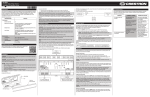
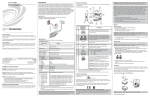
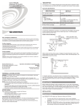
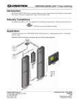
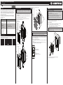
C2N-CBD-P/C2N-CBD-P-KP/C2N-CBD-E/C2N-CBF-P/C2N-CBV-P
Cameo® Keypads
Installation & Operation Guide
Assembling the Keypad (C2N-CBV-P Shown)
Assemble the Keypad
Description
The Cameo® keypads from Crestron® present a fresh, innovative concept in keypad
design, featuring a highly configurable 1-gang wall mount form factor that is at once
inviting to the touch and appealing to the eye. The C2N-CBD-P, C2N-CBD-P-KP,
C2N-CBD-E, C2N-CBF-P, and C2N-CBV-P easily install alongside other low-voltage
in-wall devices to deliver a fully customizable keypad control solution as part of a
complete Crestron control system.
The C2N-CBD-P, C2N-CBD-P-KP, C2N-CBD-E, C2N-CBF-P, and C2N-CBV-P are
functionally identical. For simplicity within this guide, the term “C2N-CBD/CBF/CBV” is
used except where noted.
Specifications
SPECIFICATION
DETAILS
Power Requirements
Cresnet® Power Usage
Attach the buttons to the keypad.
1. Arrange the button caps in position on the rear housing assembly according to the
program plan.
2. Carefully position the bezel over the button caps on the rear housing assembly.
3. Install and tighten the two supplied #2-28 x 3/16” screws.
4. Press and release each button to ensure that the button caps move freely.
Assembling the Keypad (C2N-CBD-P Shown)
Light Sensor
(C2N-CBD-P Only)
Temperature
32º F to 113º F (0º C to 45º C)
Humidity
10% to 90% RH (non-condensing)
Heat Dissipation
NOTES: Observe the following points.
• This product should be installed and used in accordance with appropriate electrical
codes and regulations.
• This product should be installed by a qualified electrician.
LED
Holes
Screws (2)
2-28 x 3/16”
3.4 Btu/h
Standard Mount
3 oz (64 g)
Flush Mount
3 oz (75 g)
LED
Holes
Bezel
Hardware Hookup
Screws (2)
2-28 x 3/16”
2 oz (50 g)
Additional Resources
Bezel
Assembling the Keypad (C2N-CBF-P Shown)
C2N-CBF-P
The C2N-CBD/CBF/CBV can be installed into an electrical box (C2N-CBD-P,
C2N-CBD-P-KP, C2N-CBD-E), flush mounted (C2N-CBF-P), or installed into a Vimar box
(C2N-CBV-P). Refer to the appropriate procedure below.
CAUTION: Excess wire pinched between the keypad and electrical box could
short out. Make sure all excess wire is completely inside the electrical box and not
between the box and the keypad.
Mounting the Keypad in a 1-Gang Electrical Box
CAUTION: Turn the Cresnet® system power off before making connections. Do not turn
the system power on until the device is fully installed in the mounting surface.
When making terminal block connections, strip the ends of the wires approximately 1/4 in
(6 mm). Use care to avoid nicking the conductors. Twist together the ends of the wires that
share a connection. Apply solder only to the ends of the twisted wires. Avoid tinning too far
up the wires or the end becomes brittle.
Make connections to the NET and INPUT ports.
• Using the supplied 4-pin connector, connect the Cresnet cable to the NET port of the
keypad.
• Using the supplied 3-pin connector (all except C2N-CBD-E), connect the contact
closure input cable to the INPUT port of the keypad.
Hardware Hookup
Visit the product page on the Crestron website (www.crestron.com) for additional
information and the latest firmware updates.
C2N-CBD-E
NOTE: Before using the C2N-CBD/CBF/CBV, ensure the device is using the latest
firmware. Check for the latest firmware for the C2N-CBD/CBF/CBV at
www.crestron.com/firmware. Firmware is loaded onto the device using Crestron
Toolbox™.
Electrical Box Installation
After the Cresnet network wiring has been installed and verified, use the following
procedure to install the keypad in a standard 1-gang electrical box.
1. Holding the keypad with the LEDs on the left, place it in the electrical box.
2. Secure the keypad using the included #6-32 x 3/4" screws.
LEDs
Weight
C2N-CBD-P/
C2N-CBD-P-KP
LEDs
1 W (0.05 A @ 24 Vdc)
Environmental
Vimar Mount
Installation
Light Sensor
NOTE: The C2N-CBD-P-KP comes pre-assembled with either ON and OFF buttons or
SCENE 1 to 4, UP, DOWN, and OFF buttons. The devices do not come with extra button
caps.
C2N-CBV-P
Light Sensor
NET:
To Control System or
Other Network Devices
LEDs
LED
Holes
Screws (2)
#6-32 x 3/4”
INPUT:
From Contact Closure
(Not Available on C2N-CBD-E)
Screws (2)
2-28 x 3/16”
Bezel
3. Attach the desired decorator style faceplate (not supplied).
4. Turn the Cresnet system power on.
Flush Mount Installation
After the Cresnet network wiring has been installed and verified, install the keypad in the
prepared hole.
1. Use the supplied template as a guide to cut the mounting hole for the C2N-CBF-P.
Ensure that the template is level and properly located on the wall. The keypad does
not offer a means of adjusting the keypad in the opening. The following illustration
(not to scale) shows the dimensions of the cutout template.
2. Holding the keypad with the LEDs on the left, place it in the hole. The spring clamp
holds the keypad in position. Turn the Cresnet system power on.
Mounting the C2N-CBF Keypad
Vimar Mount Installation
After the Cresnet network wiring has been installed and verified, install the keypad in the
Vimar style electrical box.
NOTE: Ensure that Cresnet power is off until the keypad is fully installed.
Holding the keypad with the LEDs on the left, place it in the Vimar style electrical box. The
keypad snaps into place. Turn the Cresnet system power on.
CAUTION: Excess wire pinched between the keypad and electrical box could short out.
Make sure all excess wire is completely inside the electrical box and not between the box
and the keypad.
NOTE: Be very careful when cutting the hole. There are no adjustments for
alignment with the spring clamp. The optional MMK-G1-CBF-T Mud Ring Mount
Kit for Cameo Flush Mount Keypads (sold separately) may be used if the cutout in
the mounting surface is too large for the keypad.
Troubleshooting
The following table provides corrective actions for possible trouble situations. If further
assistance is required, please contact a Crestron customer service representative.
TROUBLE
The keypad does not
function.
POSSIBLE CAUSE(S)
Use a Crestron power
supply.
The unit is not receiving
power or it is receiving
insufficient power.
Verify the cable plugged
into the NET port is
secure. Verify that the
power supply is correct.
There is a loose
connection in the network.
Verify the cable plugged
into the NET port is
secure.
The keypad does not
function. All six feedback
LEDs are on low.
The wrong Net ID is being
used.
Verify that the
C2N-CBD/CBF/CBV’s
Net ID matches the Net ID
in the software program.
The keypad does not
function or does not
function as expected.
However, it reports on
Cresnet at the proper
Net ID.
The unit is not
programmed correctly.
Use SIMPL Debugger to
check the behavior when
buttons are pressed.
Revise and reload the
program as needed to
correct the behavior.
Mounting the Keypad in a Vimar Style Electrical Box
Cutout Template (Not to Scale)
TEMPLATE - OV40096
FOR C2N-CBF
5 3/5 in
(137 mm)
CUT ALONG THIS LINE
CUT ALONG THIS LINE
THIS PIECE IS FOR CENTER LINE
REFERENCE ONLY.
DO NOT USE THIS PIECE
AS A CUTTING TEMPLATE
3 1/4 in
(83 mm)
2 7/8 in
(73 mm)
CORRECTIVE ACTION
The wrong power supply
is being used.
NOTE: If the keypad needs to be removed from the mounting surface, use a small
flat-blade screwdriver to carefully pry the keypad away from the mounting surface.
Without damaging the keypad or mounting surface, gently remove the keypad.
CLEARANCE AREA
FOR BEZEL
1 1/2 in
(39 mm)
1 3/4 in
(45 mm)
3 5/16 in
(85 mm)
Ambient Light Sensor Operation
The C2N-CBD-P, C2N-CBD-P-KP, C2N-CBF-P, and C2N-CBV-P keypads have an ambient
light sensor that can be used to automatically configure the backlight to operate in either
Day mode or Night mode.
Backlight operation is based on ambient light level and a programmed threshold. Presets
based on the keypad color set the optimum backlight level for Day mode and Night mode.
When using presets, the following occurs:
• For light-colored keypads with dark engraving, the backlight turns on dim when in
Night mode and off when in Day mode.
• For dark-colored keypads, the backlight turns on dim when in Night mode and on
bright when in Day mode.
NOTE: Backlight levels can also be set manually.
The indicator LEDs automatically adjust their brightness based on ambient light, going
bright when the keypad is well lit and going dim when the room is dark.
When two or more keypads are to be installed side by side, ensure that the backlights on all
units are in sync. To do this, there are signals available on the programming symbol to allow
one unit to act as the master backlight controller and the rest as slaves.
Refer to the Crestron Studio or SIMPL Windows help file for more information.
This product is Listed to applicable UL Standards and requirements by Underwriters Laboratories Inc.
Federal Communications Commission (FCC) Compliance Statement
This device complies with part 15 of the FCC Rules. Operation is subject to the following two
conditions: (1) This device may not cause harmful interference, and (2) this device must accept any
interference received, including interference that may cause undesired operation.
CAUTION: Changes or modifications not expressly approved by the manufacturer responsible for
compliance could void the user’s authority to operate the equipment.
NOTE: This equipment has been tested and found to comply with the limits for a Class B digital
device, pursuant to part 15 of the FCC Rules. These limits are designed to provide reasonable
protection against harmful interference in a residential installation. This equipment generates, uses and
can radiate radio frequency energy and, if not installed and used in accordance with the instructions,
may cause harmful interference to radio communications. However, there is no guarantee that
interference will not occur in a particular installation. If this equipment does cause harmful interference to
radio or television reception, which can be determined by turning the equipment off and on, the user is
encouraged to try to correct the interference by one or more of the following measures:
•
Reorient or relocate the receiving antenna
•
Increase the separation between the equipment and receiver
•
Connect the equipment into an outlet on a circuit different from that to which the receiver is
connected
•
Consult the dealer or an experienced radio/TV technician for help
The product warranty can be found at www.crestron.com/warranty.
The specific patents that cover Crestron products are listed at patents.crestron.com.
Crestron, the Crestron logo, Cameo, Cresnet, and Crestron Toolbox are either trademarks or
registered trademarks of Crestron Electronics, Inc. in the United States and/or other countries. UL
and the UL logo are either trademarks or registered trademarks of Underwriters Laboratories, Inc. in
the United States and/or other countries. Other trademarks, registered trademarks, and trade names
may be used in this document to refer to either the entities claiming the marks and names or their
products. Crestron disclaims any proprietary interest in the marks and names of others. Crestron is
not responsible for errors in typography or photography.
Industry Canada (IC) Compliance Statement
This document was written by the Technical Publications department at Crestron.
CAN ICES-3(A)/NMB-3(A)
©2015 Crestron Electronics, Inc.
Crestron Electronics, Inc.
15 Volvo Drive Rockleigh, NJ 07647
Tel: 888.CRESTRON
Fax: 201.767.7576
www.crestron.com
Installation & Operation Guide - DOC. 7063G
(2028549)
05.15
Specifications subject to
change without notice.