1
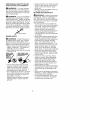
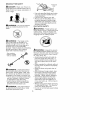
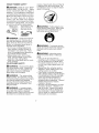
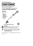
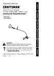
Instruction
Manual
[CRAFTSMAN+[
25cc/1.5 cu.in. 2-Cycle
17 Inch Cutting Path / 0.080 In. Line
GASOLINE
WEEDWAOKER
®
Model No.
358.795190
•
Safety
•
Assembly
•
•
Operation
Maintenance
•
Parts List
•
Espar_ol
For Occasional
Use Only
WARNING:
Read and follow all Safety Rules and Operating
Instructions
before first use of this product.
For answers
Call 7 am-7
to your questions about this product:
pm, Mon.-Sat.,
or 10 am-7 pm, Sun.
1-800-235-5878
Sears, Roebuck
530086206
10/12/01
and Co., Hoffman
_Hoo,s
listed are Central Time)
Estates,
IL 60179 U.S.A.
Warranty Statement
Safety Rules
Assembly
Operation
Maintenance
Service & Adjustments
2
3
9
10
14
15
Storage
Troubleshooting
Table
Emissions Statement
Parts List
Spanish
Parts and Ordering
FULL ONE YEAR WARRANTY
ON CRAFTSMAN
WEEDWACKER
® LINE TRIMMER.
® GASOLINE
17
18
18
20
23
Back Cover
POWERED
For one year from the date of purchase, when this Craftsman Gasoline Powered
Weedwacker
Line Trimmer is maintained, lubricated, and tuned up according to
the operating and maintenance instructions in the instruction manual, Sears will
repair, free of charge, any defect in materials or workmanship.
This warranty excludes nylon line, spark plug, and air filter, which are expendable
parts and become worn during normal use.
If this Weedwacker Line Trimmer is used for commercial purposes, this warranty applies for only 90 days from the date of purchase. If this Weedwacker Line Trimmer is
used for rental purposes, this warranty applies for only 30 days from the date of purchase. This warranty applies only while this product is in use in the United States.
WARRANTY SERVICE IS AVAILABLE BY RETURNING THE WEEDWACKER LINE TRIMMER
TO THE NEAREST SEARS STORE OR SERVICE CENTER IN THE UNITED STATES.
This warranty gives you specific legal rights, and you may also have other rights
which vary from state to state.
Sears, Roebuck and Co., D/817WA, Hoffman Estates, IL 60179
Only the following Gasoline Powered Combination Gardening Appliance powerhead models and their respective attachments have been Classified by Underwriters Laboratories, Inc., in accordance with the applicable safety requirements.
Powerbead including trimmer attachment
....................
358.795190
Optional brusbcutter attachment
............................
358.792430
Optional blower attachment
................................
358.792420
The following attachment is Listed by Underwriter's
Laboratories, Inc., in accordance with UL Standard 1602, "Gasoline-Engine-Powered,
Rigid-Cutting
Member Edgers and Edge-Trimmers="
Optional
edger attachment
.................................
358.792400
OPERATOR SAFETY
Dress properly. Always wear safety
glasses or similar eye protection
when operating, or performing maintenance, on your unit (safety
glasses are available).
Eye protection should be marked Z87.
• Always wear face or dust mask if operation is dusty.
• Always wear heavy, long pants, long
sleeves, boots, and gloves. Wearing safety leg guards is recommended.
• Always wear foot protection.
Do not
go barefoot or wear sandals. Stay
clear of spinning line.
• Secure hair above shoulder length.
Secure or remove loose clothing or
clothing with loosely hanging ties,
straps, tassels, etc. They can be
caught in moving parts.
• Being fully covered also helps protect you from debris and pieces of
toxic plants thrown by spinning line.
• Stay Alert. Do not operate this unit
when you are tired, ill, upset or under the influence of alcohol, drugs,
or medication.
Watch what you are
doing; use common sense.
• Wear hearing protection.
• Never start or run inside a closed
room or building. Breathing exhaust
fumes can kill.
• Keep handles free of oil and fuel.
• Always keep engine on the right
hand side of your body.
• Hold the unit firmly with both hands.
• Keep trimmer head (or other optional attachment) below waist level and
away from all parts of your body. Do
not raise engine above your waist.
• Keep all parts of your body away
from muffler and spinning line (or
other optional attachment).
Keep
engine below waist level. A hot muffler can cause serious burns.
• Keep firm footing and balance. Do
not overreach or use from unstable
surfaces such as ladders, trees,
steep slopes, rooftops, etc.
• Use only in daylight or good artificial
light.
• Use only for jobs explained in this
manual (or manuals for optional attachments).
4'LWARNING:
When
using
gar•
dening
appliances,
basic
safety
precautions
must
always
befollowed
to
reduce
theriskoffireandserious
injury.
Read
andfollow
allinstructions.
This power unit can be dangerous! Operator is responsible for following
instructions and warnings on unit and in
manual. Read entire instruction manual
before using unit! Be thoroughly familiar
with the controls and the proper use of
the unit. Restrict the use of this unit to
persons who have read, understand,
and will follow the instructions and
warnings on the unit and in the manual.
Never allow children to operate this unit.
INSTRUCTION
MANUAL
SAFETY
INFORMATION
ON THE UNIT
A
DANGER:
Never use blades
with line trimmer attachment.
Never
use flailing devices with any attachment. This unit (when used with supplied line trimmer attachment) is designed for line trimmer use only. Use
of any other accessories with line trimmer attachment will increase the risk
of injury.
@00
all.WARNING:
Trimmer line throws
objects violently. You and others can be
blinded/injured. Wear eye and leg
protection. Keep body parts clear of rotating line.
Eye Protection
/
Hazard 7one
lm* Boots
Keep children, bystanders, and animals
50 feet (15 meters) away. Stop unit immediately if approached.
If situations occur which are not covered in this manual, use care and
good judgment.
If you need assistance, contact your Sears Service
Center or call 1-800-235-5878.
UNIT
/ MAINTENANCE
SAFETY
• Disconnect the spark plug before
performing maintenance except carburetor adjustments.
• Look for and replace damaged or
loose parts before each use. Look
for and repair fuel leaks before use.
Keep in good working condition.
• Replace trimmer head parts that are
chipped, cracked, broken, or damaged in any other way before using
the unit.
• Maintain unit according to recommended procedures.
Keep cutting
line at proper length.
• Use only 0.080 in.(2 mm) diameter
Craftsman(_ brand line. Never use
wire, rope, string, etc.
• Install required shield properly before using the unit. Use only specified trimmer head; make sure it is
properly installed and securely fastened.
• Make sure unit is assembled correctly as shown in this manual.
• Make carburetor adjustments with
lower end supported to prevent line
from contacting any object.
• Keep others away when making carburetor adjustments.
• Use only recommended
Craftsman
accessories and replacement parts.
• Have all maintenance and service
not explained in this manual performed by a Sears Service Center.
FUEL SAFETY
• Mix and pour fuel outdoors.
• Keep away from sparks or flames.
• Use a container approved for fuel.
• Do not smoke or allow smoking near
fuel or the unit.
• Avoid spilling fuel or oil. Wipe up all
fuel spills.
• Move at least 10 feet (3 meters)
away from fueling site before starting engine.
• Stop engine and allow to cool before
removing fuel cap.
• Always store gasoline in a container
approved for flammable liquids.
TRANSPORTING
AND STORAGE
• Allow engine to cool before storing
or transporting in vehicle.
• Empty the fuel tank before storing or
transporting the unit. Use up fuel left
in the carburetor by starting the engine and letting it run until it stops.
• Store unit and fuel in area where fuel
vapors cannot reach sparks or open
flames from water heaters, electric
motors or switches, furnaces, etc.
• Store unit so line limiter blade cannot accidentally cause injury. The
unit can be hung by the tube.
• Store unit out of reach of children.
SAFETY NOTICE: Exposure to vibrations through prolonged use of gasoline powered hand tools could cause
blood vessel or nerve damage in the
fingers, hands, and joints of people
prone to circulation disorders or abnormal swellings.
Prolonged use in
cold weather has been linked to blood
vessel damage in otherwise healthy
people. If symptoms occur such as
numbness, pain, loss of strength,
change in skin color or texture, or loss
of feeling in the fingers, hands, or
joints, discontinue the use of this tool
and seek medical attention. An antivibration system does not guarantee
the avoidance of these problems. Users who operate power tools on a continual and regular basis must monitor
closely their physical condition and
the condition of this tool.
SPECIAL NOTICE: This unit is
equipped with a temperature limiting
muffler and spark arresting screen
which meets the requirements of California Codes 4442 and 4443. All U.S.
forest land and the states of California,
Idaho, Maine, Minnesota, New Jersey,
Oregon, and Washington require by
law that many internal combustion engines be equipped with a spark arresting screen. If you operate in a locale
where such regulations exist, you are
legally responsible for maintaining the
operating condition of these parts.
Failure to do so is a violation of the
law. For normal homeowner use, the
muffler and spark arresting screen will
not require any service. After 50
hours of use, we recommend that your
muffler be serviced or replaced by a
Sears Service Center.
LINE TRIMMER SAFETY
_IWARNING:
Inspect the area to
be trimmed before each use. Remove
objects (rocks, broken glass, nails,
wire, etc.) which can be thrown by or
become entangled in line. Hard objects can damage the trimmer head
and be thrown causing serious injury.
• Use only for trimming, scalping, mowing and sweeping. Do not use for
edging, pruning or hedge trimming.
• Cutting on left side of the shield will
throw debris away from the operator.
ADDITIONAL
SAFETY
FOR OPTIONAL
RULES
ATTACHMENTS
• Always push the unit slowly over the
ground. Stay alert for uneven sidewalks, holes in the terrain, large
roots, etc.
• Always use the handlebar when using edger attachment.
BLOWER/VACUUM
SAFETY
'_,WARNING:
For each optional
attachment used, read entire operators manual before use and follow all
warnings and instructions in manual
and on attachment.
,_WARNING:
Ensure handlebar
is
installed when using edger or brushcutter attachments.
Attach handlebar
above arrow on safety label on the upper tube (engine end of unit). If your
edger or brushcutter attachment does
not include a handlebar, a handlebar
accessory kit (#530071451 ) is available from your Sears Service Center.
__ndlebar
EDGER SAFETY
_L.WARNING:
Inspect the area to
be edged before each use. Remove
objects (rocks, broken glass, nails,
wire, etc.) which can be thrown by the
blade or can wrap around the shaft.
• Blade rotates momentarily after the
trigger is released. The blade can
seriously cut you or others.
• Allow blade to stop before removing
it from the cut.
Blade rotates
after the
Allow blade to stop
before removing it
from the cut.
• Throw away blades that are bent,
warped, cracked, broken or damaged in any other way. Replace
parts that are cracked, chipped, or
damaged before using the unit.
• Do not attempt to remove cut material nor hold material to be cut when
the engine is running or when cutting blade is moving.
• Always keep the wheel and depth
adjusting skid in contact with the
ground.
_,WARNING:
Inspect area before
starting unit. Remove all debris and
hard objects such as rocks, glass,
wire, etc. that can ricochet, be thrown,
or otherwise cause injury or damage
during operation.
• Do not set unit on any surface except a clean, hard area while engine
is running. Debris such as gravel,
sand, dust, grass, etc., could be
picked up by the air intake and
thrown out through discharge opening, damaging unit, property, or
causing serious injury to bystanders
or operator.
• Never place objects inside the blower tubes, vacuum tubes or blower
outlet. Always direct the blowing debris away from people, animals,
glass, and solid objects such as
trees, automobiles, walls, etc. The
force of air can cause rocks, dirt, or
sticks to be thrown or to ricochet
which can hurt people or animals,
break glass, or cause other damage.
• Never run unit without the proper
equipment attached. When using
your unit as a blower, always install
blower tubes.
• Check air intake opening, blower
tubes or vacuum tubes frequently,
always with engine stopped and
spark plug disconnected.
Keep
vents and discharge tubes free of
debris which can accumulate and
restrict proper air flow.
• Never place any object in air intake
opening as this could restrict proper
air flow and cause damage to the
unit.
• Never use for spreading chemicals,
fertilizers, or other substances which
may contain toxic materials.
• To avoid spreading fire, do not use
near leaf or brush fires, fireplaces,
barbecue pits, ashtrays, etc.
BRUSHCUTTER
SAFETY
Pri°o°s°eS
° is
_DANGER:
Blade
can thrust
vio-
lently away from material it does not cut.
Blade thrust can cause amputation of
arms or legs.
• Use only specified blade and make
sure it is properly installed and securely fastened.
• Cut from your right to your left,
• Always use the handlebar and a
properly adjusted shoulder strap
with blade (see ASSEMBLY instructions in brushcutter attachment instruction manual).
CULTIVATOR SAFETY
ArLWARNING:
Do not use trimmer
head as a fastening device for the
blade.
_WARNING:
_'WARNING:
Rotating tines can
cause serious injury. Keep away from
rotating tines. Stop the engine and
disconnect the spark plug before unclogging tines or making repairs.
The blade contin-
ues to spin after the throttle is released or engine is turned off. The
coasting blade can throw objects or
seriously cut you if accidentally
touched. Stop the blade by contacting
the left hand side of the coasting
blade with material already cut.
S_°dPeCl_ySt
ionr
'gact
._
nWARNING:
Inspect the area to
be cultivated before starting the unit.
Remove all debris and hard and sharp
objects such as rocks, vines, branches, rope, string, etc.
• Avoid heavy contact with solid objects that might stop the tines. If
heavy contact occurs, stop the engine and inspect the unit for damage.
• Never operate the cultivator without
the tine cover in place and properly
secured.
• Keep the tines and guard clear of
debris.
• After striking a foreign object, stop
the engine, disconnect the spark
plug and inspect the cultivator for
damage.
Repair before restarting.
• Disconnect attachment from the
drive engine before cleaning the
tines with a hose and water to remove any build-up.
Oil the tines to
prevent rust.
• Always wear gloves when servicing
or cleaning the tines. The tines become very sharp from use.
• Do not run unit at high speed unless
cultivating.
._
with cut materiaL_
®
A
dl_ WARNING:
Inspect the area to
be cut before each use. Remove objects (rocks, broken glass, nails, wire,
etc.) which can be thrown or become
entangled in the blade or trimmer line.
• Throw away and replace blades that
are bent, warped, cracked, broken
or damaged in any other way.
• Install required shield properly before using the unit. Use the metal
shield for all metal blade use.
,_.WARNING:
Only use brushcutter attachments that provide a metal
shield with proboscis nose.
6
HEDGE TRIMMER
SAFETY
,_DANGER:
RISK OF CUT; KEEP
HANDS AWAY FROM BLADE - Blade
moving. Keep hands, face and feet at
a distance from all moving parts. Do
not attempt to touch or stop the blade
when it is moving.
moves momentarily after the trigger is
released. Do not attempt to clear away
cut material when the blade is in motion.
Make sure the switch is in the OFF position, the spark plug wire is disconnected, and the blade has stopped
moving before removing jammed material from the cutting blade. Do not grab
or hold the unit by the cutting blade.
Blades move
Allow blades to stop
momentarily
before removing
after the
them from the cut.
trigger is
'_,WARNING:
Falling objects can
cause severe head injury. Wear head
protection when operating this unit
with a pole pruner attachment.
_WARNING:
Inspect the area before starting the unit. Remove all debris and hard objects such as rocks,
glass, wire, etc. that can ricochet, be
thrown, or otherwise cause injury or
damage during operation.
• Do not use a cutting blade that is
bent, warped, cracked, broken or
damaged in any other way. Have
worn or damaged parts replaced by
your Sears Service Center.
• Always keep unit in front of your
body. Keep all parts of your body
away from the cutting blade.
• Keep the cutting blade and air vents
clear of debris.
POLE PRUNER SAFETY
_WARNING:
Reciprocating blade
can cause severe injury. Inspect the
unit before use. Do not operate unit
with a bent, cracked or dull blade.
Keep away from the blade.
_WARNING:
The reciprocating
blade is sharp. Do not touch. To prevent serious injury, always stop engine
and ensure blades have stopped
moving, disconnect spark plug, and
wear gloves when changing or handling the blade.
_.WARNING:
A coasting blade
can cause injury while it continues to
move after the engine is stopped.
Maintain proper control of the unit until
the blade has completely stopped
A
4_WARNING:
To prevent serious
injury, do not use more than one boom
extension with a pole pruner attachment.
_,WARNING:
Keep the pruner
away from power lines or electrical
wires.
• Only use for pruning limbs or
branches up to 4 inches in diameter.
• Do not operate the unit faster than
the speed needed to prune. Do not
run the unit at high speed when not
pruning.
• Always stop the unit when work is
delayed or when walking from one
cutting location to another.
• If you strike or become entangled
with a foreign object, stop the engine
immediately and check for damage=
Have any damage repaired by a
Sears Service Center before attempting further operations.
Discard
blades that are bent, warped,
cracked or broken.
• Stop the unit immediately if you feel
excessive vibration. Vibration is a
sign of trouble. Inspect thoroughly
for loose nuts, bolts or damage before continuing.
Contact Sears Service for repair or replacement of affected parts as necessary.
SNOW THROWER
SAFETY
_IWARNING:
Keep hands and
feet away from the rotor when starting
or running the engine. Never attempt
to clear the rotor with the engine/motor
running. Stop engine and disconnect
spark plug before unclogging snow or
debris from discharge chute or when
adjusting vanes,
....
I
4BIWARNING:
Never lean over discharge chute. Rocks or debris could
be thrown into the eyes and face and
cause serious injury or blindness.
WARNING:
Inspect the area
where the unit is to be used. Remove
objects that could be thrown or damage the unit. Some objects may be
hidden by fallen snow - be alert for
the possibility.
• Direct material discharge away from
glass enclosures, automobiles, etc.
• Do not run engine at high speed
while not removing snow.
• Be attentive when using the snowthrower, and stay alert for holes in
the terrain and other hidden hazards.
• Make sure the rotor will spin freely
before attaching the snowthrower to
the powerhead.
• If the rotor will not rotate freely due
to frozen ice, thaw the unit before
thoroughly before attempting to operate under power.
• Keep the rotor clear of debris.
• Do not throw snow near other
people. The snow thrower could
propel small objects at high speed
causing injury.
• After striking a foreign object, stop
the engine, disconnect spark plug
and inspect the snowthrower for
damage and repair if necessary before restarting unit.
• Never operate the snowthrower near
glass enclosures, automobiles and
trucks.
• Never attempt to use the snowthrower on a roof.
• Never operate the snowthrower near
window wells, dropoffs, etc.
• Never discharge snow onto public
roads or near moving traffic.
• Clear snow from slopes by going up
and down; never across. Use caution when changing directions.
Never clear snow from steep slopes.
• Let snowthrower run for a few minutes after clearing snow so moving
parts do not freeze.
• Look behind and use care when
backing up. Exercise caution to
avoid slipping or falling, especially
when operating in reverse.
• Know how to stop quickly.
CARTON
CONTENTS
Coupler
Primary Hole
\
/ Guide Recess
Check
carton
contents
against
thefollowing
list.
Model358,795190
• Powerhead
• Trimmer
Attachment
U I
Lookingl _,_"
pper
Release
Lower
• Shield
Tube
Attachment
Button
• Wing
Nut(screwed
ontoshield)
• Container
ofOil
dmWARNING:
Make sure the lockExamine
parts
fordamage.
Donot
usedamaged
parts.
ing/release button is locked in the priNOTE:
Ifyouneedassistance
orfind mary hole and the knob is securely
tightened before operating the unit.
partsmissing
ordamaged,
call
All attachments are designed to be
1-800-235-5878.
used in the primary hole.
Itisnormal
forthefuelfiltertorattlein
For optional attachments, see the AStheempty
fueltank.
SEMBLY section of the applicable atFinding
fueloroilresidue
onmuffler
is tachment instruction manual.
normal
duetocarburetor
adjustmentsATTACHING SHIELD
andtesting
donebythemanufacturer.
_,WARNING:
The shield must be
ASSEMBLY
,_WARNING:
If received
properly installed. The shield provides
partial protection from the risk of thrown
objects to the operator and others and
is equipped with a line limiter blade
which cuts excess line to the proper
length. The line limiter blade (on underside of shield) is sharp and can cut you.
For proper orientation of shield, see
KNOW YOUR TRIMMER illustration in OPERATION section.
as-
sembled, repeat all steps to ensure
your unit is properly assembled and all
fasteners are secure.
INSTALLING
MENT
TRIMMER
ATTACH-
CAUTION:
When installing trimmer
attachment, place the unit on a flat
surface for stability.
1. Loosen the coupler by turning the
knob counterclockwise.
1.
2.
3.
4.
Coupler
Remove wing nut from shield.
Insert bracket into slot as shown.
Pivot shield until bolt passes
through hole in bracket.
Securely tighten wing nut onto
bolt.
_OOSEN
Shield
_
TIGHTEN
2.
3.
4.
5.
_,_
....__..----_/\\
Slot
Bracket
Knob
Remove the tube cap from the
trimmer attachment (if present).
Position locking/release
button of
attachment into guide recess of
coupler.
Push the attachment into the coupler until the locking/release
button
snaps into the primary hole.
Before using the unit, tighten the
knob securely by turning clockwise.
\
_
Line Limiter Blade f
ADJUSTING
Wing
Nut
THE HANDLE
_,WARNING:
When adjusting tile
handle, be sure it remains between
the trigger and the arrow on the safety
label.
1. Loosen wing nut on handle.
2. Rotate the handle on the tube to
an upright position; retighten wing
nut.
9
KNOW YOUR TRIMMER
READ THiS iNSTRUCTiON MANUAL AND SAFETY RULES BEFORE OPERATING YOUR
UNIT. Compare the illustrations with your unit to familiarize yourself with the location
of the various controls and adjustments. Save this manual for future reference.
Assist Handle
J
Coupler
Tube
,_
Trimmer
Head
ON/OFF
Spark
Switch
Plug
Shield
Primer Bulb
Line Limiter
Blade
S
Throttle Trigger
Muffler
ON/OFF SWITCH
The ON/OFF switch is located on the
trigger handle and is used to stop the
engine. Move the switch to the OFF
position to stop the engine.
PRIMER BULB
The PRIMER BULB removes air from
the carburetor and fuel lines and fills
them with fuel. This allows you to start
the engine with fewer pulls on the
starter rope. Activate the primer bulb
by pressing it and allowing it to return
to its original form=
CHOKE
The CHOKE helps to supply fuel to the
engine to aid in cold starting. Activate
the choke by moving the choke lever to
the FULL CHOKE position. After the engine attempts to start, move the choke
lever to the HALF CHOKE position. Once
engine has started, move the choke lever to the OFF CHOKE position.
COUPLER
The COUPLER enables optional attachments to be installed on the unit.
BEFORE STARTING
follow instructions
container.
_WARNING:
ENGINE
Be sure to read
the fuel information in the safety rules
before you begin. If you do not understand the safety rules, do not attempt
to fuel your unit. Call 1-800-235-5878.
FUELING ENGINE
,_WARNING:
Remove fuel cap
slowly when refueling.
This engine is certified to operate on
unleaded gasoline. Before operation,
gasoline must be mixed with a good
quality 2-cycle air-cooled engine oil.
We recommend Craftsman brand oil.
Mix gasoline and oil at a ratio of 40:1
(A 40:1 ratio is obtained by mixing 8.2
ounces of oil with 1 gallon of unleaded
gasoline). DO NOT USE automotive oil
or boat oil. These oils will cause
engine damage. When mixing fuel,
printed on
Once oil is added to gasoline, shake
container momentarily to assure that
the fuel is thoroughly mixed. Always
read and follow the safety rules
relating to fuel before fueling your unit.
IMPORTANT
Experience indicates that alcohol
blended fuels (called gasohol or using
ethanol or methanol) can attract moisture which leads to separation and
formation of acids during storage.
Acidic gas can damage the fuel system of an engine while in storage.
To avoid engine problems, empty the
fuel system before storage for 30 days
or longer. Drain the gas tank, start the
engine and let it run until the fuel lines
and carburetor are empty. Use fresh
fuel next season.
10
Never
useengine
orcarburetor
clean- 8.
erproducts
inthefueltankorpermanentdamage
mayoccur.
SeetheSTORAGE
section
foradditionalinformation.
HOW
TOSTOP
YOUR
UNIT
• Tostoptheengine,
move
the
ON/OFF
switch
totheOFF
position.
• Ifengine
doesnotstop,move
choke
lever
toFULL
CHOKE
position.
ON/OFF
eh
Throttle Trigger
_
HOW TO START
\
YOUR UNIT
_f_'WARNING:
The trimmer
head
will turn while starting the engine.
Avoid any contact with the muffler. A
hot muffler can cause serious burns.
STARTING A COLD ENGINE (or a
warm engine after running out of
fuel)
1.
2.
3.
4.
5.
Set unit on a flat surface.
Move ON/OFF switch to the ON
position.
Slowly press the primer bulb 6
times.
Move choke lever to the FULL
CHOKE position.
Squeeze the throttle trigger fully
and hold through all remaining
steps.
Starter Primer Bulb
Handle
Lever
6.
7.
X_
_-,"'t'!_J,.I
t /" Muffler
Pull starter rope handle sharply
until engine sounds as if it is trying
to start, but do not pull rope more
than 6 times.
As soon as engine sounds as if it
is trying to start, move choke lever
to the HALF CHOKE position.
Pull starter rope sharply until engine
runs, but no more than 6 pulls.
NOTE: If the engine doesn't start
after 6 pulls (at the HALF CHOKE
position), move the choke lever to
the FULL CHOKE position and
press the primer bulb 6 times.
Squeeze and hold the throttle trigger and pull the starter rope 2
more times. Move the choke lever
to the HALF CHOKE position and
pull the starter rope until the engine runs, but no more than 6
pulls. If the engine still doesn't
start, it is probably flooded. Proceed to STARTING A FLOODED ENGINE.
9. Once the engine starts, allow it to
run 10 seconds, then move the
choke lever to the OFF CHOKE
position. Allow the unit to run for
30 more seconds at OFF CHOKE
before releasing the throttle trigger.
NOTE: If engine dies with the
choke lever in the OFF CHOKE
position, move the choke lever to
the HALF CHOKE position and pull
the rope until engine runs, but no
more than 6 pulls.
STARTING A WARM ENGINE
1. Move ON/OFF switch to the ON
position.
2. Move the choke lever to the HALF
CHOKE position.
3. Squeeze and hold the throttle trigger. Keep throttle trigger fully
squeezed until the engine runs
smoothly.
4. Pull starter rope sharply until engine runs, but no more than 5
pulls.
5. Allow engine to run 15 seconds,
then move the choke lever to the
OFF CHOKE position.
NOTE: If engine has not started, pull
starter rope 5 more pulls. If engine still
does not run, it is probably flooded.
STARTING A FLOODED ENGINE
Flooded engines can be started by
placing the choke lever in the OFF
CHOKE position; then, pull the rope to
clear the engine of excess fuel. This
could require pulling the starter handle
many times depending on how badly
the unit is flooded.
If the unit still doesn't start, refer to
TROUBLESHOOTING TABLE or call
1-800-235-5878.
11
OPERATING
THE COUPLER
This model is equipped with a coupler
which enables optional attachments to
be installed. The optional attachments are:
Edger .................
358.792400
Cultivator ..............
358.792410
Blower ................
358.792420
Brushcutter ............
358.792430
_.WARNING:
Always stop unit
and disconnect spark plug before removing or installing attachments.
REMOVING TRIMMER ATTACHMENT (OR OTHER OPTIONAL ATTACHMENTS)
CAUTION:
When removing or installing attachments,
place tile unit on a
flat surface for stability.
1. Loosen the coupler by turning the
knob counterclockwise.
upper Tube
Coupler
Lower
\
Attachment
TIGHTEN
2.
Press and
button.
Knob
hold the
locking/release
Locking/Release
Button
Upper Tube
Lower Attachment
3.
While securely holding the engine
and upper tube, pull the attachment straight out of the coupler.
INSTALLING
OPTIONAL ATTACHMENTS
1. Remove the tube cap from the attachment (if present).
2. Position locking/release
button of
attachment into guide recess of
coupler.
3. Push the attachment into the coupler until the locking/release
button
snaps into the primary hole.
4. Before using the unit, tighten the
knob securely by turning clockwise.
_WARNING:
Make sure the lock-
ing/release button is locked in the primary hole and the knob is securely
tightened before operating the unit.
Coupler
Primary
Upper
Tube
OPERATING
Locking/
Release
Button
Hole
Guide Recess
Attachment
POSITION
Protection
Long Pants
ALWAYS WEAR:
Heavy Shoes
Cut from your right to your left.
_tWARNING:
Always wear eye
protection. Never lean over the trimmer head. Rocks or debris can ricochet or be thrown into eyes and face
and cause blindness or other serious
injury.
Do not run the engine at a higher
speed than necessary. The cutting
line will cut efficiently when the engine
is run at less than full throttle. At lower
speeds, there is less engine noise and
vibration. The cutting line will last
longer and will be less likely to "weld"
onto the spool.
Always release the throttle trigger and
allow the engine to return to idle
speed when not cutting.
To stop engine:
• Release the throttle trigger.
• Move the ON/OFF switch to the OFF
position.
TRIMMER LINE ADVANCE
The cutting head advances
line automatically.
Do not tap head on the
ground to advance line. This may
break parts and cause cutting head to
malfunction.
Upon unit start up, the line will advance
automatically to the correct cutting path
length.
Always keep the shield in place when
the tool is being operated.
WARNING:
Use only 0.080"
(2 mm) diameter round line. Other
sizes and shapes of line will not advance properly and will result in improper cutting head function or can
12
cause
serious
injury.
Donotuseother
materials
suchaswire,string,
rope,
etc.Wirecanbreak
offduring
cutting
andbecome
a.dangerous
missile
that
cancause
serious
injury.
CUTTING
METHODS
_WARNING:Useminimum
speed
anddonotcrowd
thelinewhen
cutting
around
hardobjects
(rock,
gravel,
fenceposts,
etc.), which can
damage the trimmer head, become
entangled in the line, or be thrown
causing a serious hazard.
• The tip of the line does the cutting.
You will achieve the best performance and minimum line wear by not
crowding the line into the cutting
area. The right and wrong ways are
shown below.
Tip of the Une
Line Crowded Into
Does The Cutting
Work Area
SCALPING - The scalping technique
removes unwanted vegetation down
to the ground. Hold the bottom of the
trimmer head about 3 in. (8 cm) above
the ground and at an angle. Allow the
tip of the line to strike the ground
around trees, posts, monuments, etc.
This technique increases line wear.
Scalping
MOWING - Your trimmer is ideal for
mowing in places conventional lawn
mowers cannot reach. In the mowing
position, keep the line parallel to the
ground. Avoid pressing the head into
the ground as this can scalp the
ground and damage the tool.
Mowing
Right
• The line will easily remove grass
and weeds from around walls,
fences, trees and flower beds, but it
also can cut the tender bark of trees
or shrubs and scar fences.
• For trimming or scalping, use less
than full throttle to increase line life
and decrease head wear, especially:
• During light duty cutting.
• Near objects around which the line
can wrap such as small posts,
trees or fence wire.
• For mowing or sweeping, use full
throttle for a good clean job.
TRIMMING - Hold the bottom of the
trimmer head about 3 in. (8 cm) above
the ground and at an angle. Allow only
the tip of the line to make contact. Do
not force trimmer line into work area.
")}I), _J
SWEEPING - The fanning action of
the rotating line can be used to blow
away loose debris from an area. Keep
the line parallel to and above the area
surface and swing the tool from side
to side.
Sweeping
Trimming
x
3 in. (8 cm)
Above Ground
13
MAINTENANCE
SCHEDULE
WARNING:
Disconnect the spark plug before performing maintenance
except for carburetor adjustments.
CARE & MAINTENANCE TASK
WHEN TO PERFORM
Check for loose fasteners
Check for damaged
Before each use
and parts
Before each use
or worn parts
After each use
Inspect and clean unit and labels
Clean air filter
Inspect muffler and spark arresting
Replace
Every 5 hours of operation
screen
Every 50 hours of operation
spark plug
GENERAL RECOMMEN DATIONS
The warranty on this unit does not
cover items that have been subjected
to operator abuse or negligence. To
receive full value from the warranty,
the operator must maintain unit as
instructed in this manual. Various adjustments will need to be made periodically to properly maintain your unit.
CHECK FOR LOOSE
FASTENERS AND PARTS
• Spark Plug Boot
• Air Filter
• Housing Screws
• Assist Handle Screw
• Debris Shield
CHECK FOR DAMAGED OR
WORN PARTS
Contact Sears Service Center for replacement of damaged or worn parts.
• ON/OFF Switch - Ensure ON/OFF
switch functions properly by moving
the switch to the OFF position. Make
sure engine stops; then restart engine and continue.
• Fuel Tank - Discontinue use of unit
if fuel tank shows signs of damage
or leaks.
• Debris Shield - Discontinue use of
unit if debris shield is damaged.
INSPECT AND CLEAN UNIT AND LABELS
• After each use, inspect complete
unit for loose or damaged parts.
Clean the unit and labels using a
damp cloth with a mild detergent.
• Wipe off unit with a clean dry cloth.
Yearly
CLEAN AIR FILTER
A dirty air filter decreases engine performance and increases fuel consumption and harmful emissions. Always clean after every 5 hours of
operation.
1. Clean the cover and the area
around it to keep dirt from falling
into the carburetor chamber when
the cover is removed.
2. Remove parts as illustrated.
NOTE: To avoid creating a fire hazard
or producing harmful evaporative
emissions, do not clean filter in gasoline or other flammable solvent.
3. Wash the filter in soap and water.
4. Allow filter to dry.
5. Add a few drops of oil to the filter;
squeeze the filter to distribute oil.
6. Replace parts.
(_
._'1_
Air Filter
'_b_
.__
Screws
Cover
REPLACE SPARK PLUG
Replace the spark plug each year to
ensure the engine starts easier and
runs better. Set spark plug gap at
0.025 in. Ignition timing is fixed and
nonadjustable.
1. Twist, then pull off spark plug boot.
2. Remove spark plug from cylinder
and discard.
3. Replace with Champion RCJ-8Y
spark plug and tighten with a 3/4
in. socket wrench (10-12 ft.-Ibs).
4. Reinstall the spark plug boot.
14
LINE REPLACEMENT
Pre-wound spools offer the most convenient method for replacing line and
ensuring optimum performance.
• Replacement spools are colorcoded to ensure use of the correct
spool with your unit. Be sure to use
the same color spool as the existing
spool.
NOTE: Always clear dirt and debris
from cutting head components when
performing any type of maintenance.
• Hold spool and unscrew cap by turning in the direction shown on top of
the cap.
• Remove line guide ring and spool.
Line guide ring
shown on the spool (counterclockwise).
3. Continue feeding line into spool,
leaving 4 - 6 inches (10 - 15 cm)
unwound from center of spool.
INSTALLING
SPOOL WITH LINE
1. Install replacement spool.
2. Thread line through line guide ring.
Line thfroughguide ring
/i
-
Replacement Spool
3.
Use a pre-wound
with line. If using
remove tape strip
REFILLING THE
spool or refill
a pre-wound
from line and
SPOOL WITH
spool
spool,
spool.
LINE
Rest guide ring on spool and place
line through slot. Allow line to extend 4 - 6 inches (10 - 15 cm)
from center of spool.
4. Ensure line remains in slot while
screwing cap on to the shaft.
Only tighten cap hand tight!
CARBURETOR
ADJUSTMENT
_:_,WARNING:
_.WARNING:
Use only 0.080" (2
ram) diameter round line. Other
sizes and shapes of line will not advance properly and will result in improper cutting head function or can
cause serious injury. Do not use other
materials such as wire, string, rope,
etc. Wire can break off during cutting
and become a dangerous missile that
can cause serious Injury.
1. Cut a length of 30 feet of 0.080" (2
mm) diameter round Craftsman
brand line.
2.
Spool
Insert one end of line into center
cavity of empty spool. Ensure line
will feed into spool in the direction
The trimmer
head
will be spinning during most of this
procedure. Wear your protective
equipment and observe all safety precautions. After making mixture adjustments, recheck idle speed. The trimmer head and any optional attachments must not move/spin at idle
speed.
Carburetor adjustment is critical and if
done improperly can permanently
damage the engine as well as the carburetor. If you require further assistance or are unsure about performing
this procedure, call our customer assistance help line at 1-800-235-5878.
Old fuel, a dirty air filter, a dirty fuel filter, or flooding may give the impression of an improperly adjusted carburetor. Check these conditions before
adjusting the carburetor.
The carburetor has been carefully set
at the factory. Adjustments may be
necessary if you notice any of the following conditions:
• The trimmer head and/or any optional attachment moves at idle. See
iDLE SPEED-T under adjusting procedure.
• Engine will not idle. See iDLE
SPEED-T under adjusting procedure.
15
• Engine
diesorhesitates
instead
of
the engine stalls, idle speed is too
slow.
accelerating.
SeeACCELERATION
CHECK
under
adjusting
procedure. • Turn IDLE SPEED screw (T) clock• Lossofcutting
power.
SeeMIXTURE wise to increase engine speed.
ADJUSTMENT
(LorH)under
adjust- • Turn IDLE SPEED screw (T) counteringprocedure.
clockwise to decrease engine
speed.
There
arethreeadjustment
screws
on
thecarburetor.
Thelowspeed
adjust- Low Speed Adjustment -L
mentscrew
ismarked
withtheletterL, 1. Allow the engine to idle.
andthehighspeed
adjustment
screw
is
low speed mixture screw (L)
marked
withtheletter
14.
Thethirdscrew 2. Turn
slowly clockwise until the speed
is theidleadjustment
screwandis
begins to drop.
marked
withtheletter
T.
3. Turn the low speed mixture screw
Adjustment
(_._
stment
(L)
4.
Idle
Screw
Adjustment
(T)
ADJUSTING
PROCEDURE
CAUTION:
Do not force plastic limiter
cap on screws beyond the built-in
stops or damage will occur. Be sure
trimmer line is extended to the maximum length allowed by the line limiter
blade.
Initial Settings:
1= Turn both mixture screws (L and
H) counterclockwise
until they
stop.
2= Turn the IDLE SPEED screw (T)
clockwise until it stops. Now turn
counterclockwise
4 1/2 tu rns.
3= Start engine, cut grass for 3 minutes, then proceed to adjust
screws according to the instructions below. If engine performance at initial settings is acceptable, no further adjustments are
necessary. If engine does not
start, refer to TROUBLESHOOTING
TABLE. If still unable to remedy
situation, call 1-800-235-5878.
Idle Speed-T
Allow engine to idle. If the trimmer
head moves, idle speed is too fast.
(L) counterclockwise
until the
speed increases and then starts to
drop again.
Set the low speed mixture screw
(L) at the midpoint between the
two positions.
Readjust the idle speed (See IDLE
SPEED-T).
High Speed Mixture-H
CAUTION:
Do not operate engine at
full throttle for prolonged periods while
making high speed adjustments as
damage to the engine can occur. Adjust the high speed screw 1/16 of a
turn at a time. A 1/16 turn is about the
width of the slot in the top of the
screw.
1. Allow the engine to idle.
2. Squeeze the throttle trigger fully.
Turn the high speed mixture screw
(H) counterclockwise
until it stops.
3. Turn the high speed mixture screw
(H) 1/16 of a turn clockwise at a
time until the engine runs smoothly.
After completing adjustments, check
for acceleration and trimmer head
movement at idle. Reset if necessary.
Acceleration
If
Check
If engine dies or hesitates instead of
accelerating, turn the low speed mixture screw (L) counterclockwise
until
you have smooth acceleration.
16
dI_bWARNING:
Perform the following steps after each use:
• Allow engine to cool before storing
or transporting.
• Store unit and fuel in a well ventilated area where fuel vapors cannot
reach sparks or open flames from
water heaters, electric motors or
switches, furnaces, etc.
• Store unit with all guards in place.
Position unit so that any sharp object cannot accidentally cause injury.
• Store unit and fuel well out of the
reach of children.
SEASONAL
STORAGE
Prepare unit for storage at end of season or if it will not be used for 30 days
or more.
If your unit is to be stored for a period
of time:
• Clean the entire unit before lengthy
storage.
• Store in a clean dry area.
• Lightly oil external metal surfaces.
FUEL SYSTEM
Under FUELING ENGINE in the OPERATION section of this manual, see message labeled IMPORTANT regarding
the use of gasohol in your engine.
Fuel stabilizer is an acceptable alter-
native in minimizing the formation of
fuel gum deposits during storage. Add
stabilizer to the gasoline in the fuel
tank or fuel storage container. Follow
the mix instructions found on stabilizer
container. Run engine at least 5 minutes after adding stabilizer.
Craftsman 40:1,2-cycle
engine oil (air
cooled) is already blended with fuel
stabilizer. If you do not use this Sears
oil, you can add a fuel stabilizer to
your fuel tank.
ENGINE
• Remove spark plug and pour 1 teaspoon of 40:1,2-cycle
engine oil (air
cooled) through the spark plug
opening. Slowly pull the starter rope
8 to 10 times to distribute oil.
• Replace spark plug with new one of
recommended
type and heat range.
• Clean air filter.
• Check entire unit for loose screws,
nuts, and bolts. Replace any damaged, broken, or worn parts.
• At the beginning of the next season,
use only fresh fuel having the proper
gasoline to oil ratio.
OTHER
• Do not store gasoline from one season to another.
• Replace your gasoline can if it starts
to rust.
17
TROUBLESHOOTING
,_
TABLE
WARNING:
Always stop unit and disconnect spark plug before performing all of the recommended
remedies below except remedies that require
operation of the unit.
TROUBLE
CAUSE
REMEDY
Engine will not
start.
1. ON/OFF switch
OFF position.
2. Engine flooded.
in
3. Fuel tank empty.
4. Spark plug not firing.
5. Fuel not reaching
carburetor.
6. Carburetor requires
adjustment.
1. Move ON/OFF switch to ON.
2. See "Starting a Flooded Engine" in
Operation Section.
3. Fill tank with correct fuel mixture.
4. Install new spark plug.
5. Check for dirty fuel filter; replace.
Check for kinked or split fuel line;
repair or replace.
6. See "Carburetor Adjustment"
in
Service and Adjustments Section.
Engine will
not idle
properly.
1. Carburetor requires
adjustment.
2. Crankshaft seals worn.
3. Compression
low.
1. See "Carburetor Adjustment"
in
Service and Adjustments Section.
2. Contact Sears Service Center.
3. Contact Sears Service Center.
Engine will not
accelerate,
lacks power.
or dies under
a load.
1. Air filter dirty.
2. Spark plug fouled.
1. Clean or replace air filter.
2. Clean or replace plug
and regap.
3. See "Carburetor Adjustment"
in
Service and Adjustments Section.
4. Contact Sears Service Center.
Engine
smokes
excessively.
3. Carburetor requires
adjustment.
4. Carbon build-up on
muffler outlet screen.
5. Compression
low.
1. Choke partially on.
2. Fuel mixture incorrect.
3. Air filter dirty.
4. Carburetor requires
adjustment.
Engine
hot.
runs
1. Fuel mixture
incorrect.
2. Spark plug incorrect.
3. Carburetor requires
adjustment.
4. Carbon build-up on
muffler outlet screen.
YOUR WARRANTY
RIGHTS AND
OBLIGATIONS:
The U. S. Environmental Protection Agency and Sears,
Roebuck and Co., U.S.A., are pleased
to explain the emissions control system warranty on your lawn and garden
equipment engine. All new utility and
lawn and garden equipment engines
must be designed, built, and equipped
to meet the stringent anti-smog standards. Sears must warrant the emission control system on your lawn and
garden equipment engine for the periods of time listed below provided there
has been no abuse, neglect, or improper maintenance of your lawn and
5. Contact
Sears Service Center.
1. Adjust choke.
2. Empty fuel tank and refill with
correct fuel mixture.
3. Clean or replace air filter.
4. See "Carburetor
Adjustment" in
Service and Adjustments Section.
1. See "Fueling Engine" in Operation
section.
2. Replace with correct spark plug.
3. See "Carburetor
Adjustment" in
Service and Adjustments Section.
4. Contact Sears Service Center.
garden equipment engine. Your emission control system includes parts
such as the carburetor and the ignition
system. Where a warrantable condition exits, Sears will repair your lawn
and garden equipment engine at no
cost to you. Expenses covered under
warranty include diagnosis, parts and
labor. MANUFACTURER'S
WARRANTY COVERAGE:
If any emissions related part on your engine (as
listed under Emissions Control Warranty Parts List) is defective or a defect in the materials or workmanship
of
the engine causes the failure of such
an emission related part, the part will
18
berepaired
orreplaced
bySears.
OWNER'S WARRANTY
RESPONSIBILITIES: As the lawn and garden
equipment engine owner, you are responsible for the performance of the
required maintenance listed in your
instruction manual. Sears recommends that you retain all receipts covering maintenance on your lawn and
garden equipment engine, but Sears
cannot deny warranty solely for the
lack of receipts or for your failure to
ensure the performance of all scheduled maintenance.
As the lawn and
garden equipment engine owner, you
should be aware that Sears may deny
you warranty coverage if your lawn
and garden equipment engine or a
part of it has failed due to abuse, neglect, improper maintenance, unapproved modifications, or the use of
parts not made or approved by the
original equipment manufacturer.
You
are responsible for presenting your
lawn and garden equipment engine to
a Sears authorized repair center as
soon as a problem exists. Warranty
repairs should be completed in a reasonable amount of time, not to exceed
30 days. If you have any questions
regarding your warranty rights and responsibilities, you should contact your
nearest authorized service center or
call Sears at 1-800-469-4663
WARRANTY COMMENCEMENT
DATE:
The warranty period begins on the
date the lawn and garden equipment
engine is purchased.
LENGTH OF
COVERAGE:
This warranty shall be
for a period of two years from the initial date of purchase. WHAT IS COVERED: REPAIR OR REPLACEMENT
OF PARTS. Repair or replacement of
any warranted part will be performed
at no charge to the owner at an approved Sears servicing center. If you
have any questions regarding your
warranty rights and responsibilities,
you should contact your nearest authorized service center or call Sears at
1-800-469-4663.
WARRANTY
PERIOD: Any warranted part which is not
scheduled for replacement as required maintenance, or which is
scheduled only for regular inspection
to the effect of "repair or replace as
necessary" shall be warranted for 2
years. Any warranted part which is
scheduled for replacement as required maintenance shall be warranted for the period of time up to the
first scheduled replacement point for
that part. DIAGNOSIS: The owner
shall not be charged for diagnostic labor which leads to the determination
that a warranted part is defective if the
diagnostic work is performed at an approved Sears servicing center. CONSEQUENTIAL
DAMAGES: Sears
may be liable for damages to other
engine components caused by the
failure of a warranted part still under
warranty. WHAT IS NOT COVERED:
All failures caused by abuse, neglect,
or improper maintenance are not covered. ADD-ON OR MODIFIED
PARTS: The use of add-on or modified
parts can be grounds for disallowing a
warranty claim. Sears is not liable to
cover failures of warranted parts
caused by the use of add-on or modified parts. HOW TO FILE A CLAIM: If
you have any questions regarding
your warranty rights and responsibilities, you should contact your nearest
authorized service center or call Sears
at 1-800-469-4663.
WHERE TO GET
WARRANTY
SERVICE: Warranty services or repairs shall be provided at all
Sears service centers, call:
1-800-469-4663.
MAINTENANCE, REPLACEMENT AND REPAIR OF EMISSION RELATED PARTS: Any Sears
approved replacement part used in
the performance of any warranty
maintenance
or repair on emission related parts will be provided without
charge to the owner if the part is under
warranty. EMISSION CONTROL
WARRANTY
PARTS LIST: Carburetor, Ignition System: Spark Plug (covered up to maintenance schedule),
Ignition Module. MAINTENANCE
STATEMENT: The owner is responsible for the performance of all required
maintenance
as defined in the instruction manual.
19