1
Operator's Manual
ICRRFTSMR
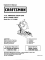
14 in. ABRASIVE CHOP SAW
WITH LASER TRAC ®
Model No. 137.212890
CAUTION:
Before using this Chop Saw,
read this manual and follow
all its Safety Rules and
Operating Instructions
Customer
Help
•
•
•
•
•
Sears
Line
Corporation
Parts
&
Repair Center
1-800-488-1222
For Technical
Support
1-800-843-1682
Sears Brands Management
Safety Instructions
Installation
Operation
Maintenance
Parts List
Hoffman
Estates, IL 60179
USA
See the full line of Craftsman ® products at craftsman.com
Click on the Craftsman Club ® link and join today!
Part No. 137212890001
Printed in China
SECTION
PAGE
Warranty ........................................
Product Specifications ......................
Power Tool Safety ............................
Chop Saw Safety .................................
Electrical Requirements and Safety ......
Carton Contents ..................................
SECTION
2
2
3
4
7
8
PAGE
Know Your Chop Saw ...............................
Assembly and Adjustments .....................
Operation ...........................................
Maintenance ......................................
Troubleshooting Guide ...........................
Parts List ..............................................
CRAFTSMAN
9
10
13
14
15
16
FULL WARRANTY
If this Craftsman product fails due to a manufacturer's defect in material or workmanship with one year from the date
of purchase, return it to any Sears store, Sears Parts & Repair Service Center, or other Craftsman outlet in the United
States for free free repair ( or replacement if repair proves impossible). This warranty does not include expendable
parts such as saw blades which can wear out from normal use within the warranty period. This warranty applies for
only 90 days from the date of purchase if this product is ever used for commercial or rental purposes. This warranty
gives you special legal rights,and you may also have other rights which vary from state to state.
Sears, Roebuck
and Co., Hoffman
Estates, IL 60179
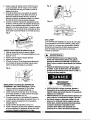
],A, WARNING I
Some dust created by using power tools contains chemicals known to the state of California to cause cancer
and birth defects or other reproductive harm. Some examples of these chemicals are:
•
Lead from lead-based paints
•
Crystalline silica from bricks, cement and other masonry products
•
Arsenic and chromium from chemically treated lumber
Your risk from these exposures varies, depending on how often you do this type of work. To reduce your
exposure to these chemicals, work in a well ventilated area and work with approved safety equipment such as
dust masks that are specially designed to filter out microscopic particles.
MOTOR
HP (Maximum developed) ..........................
3.5
Extension wing ......................................
Yes
Type ...........................................................
Universal
Laser guide ...........................................
Yes
Amps ..........................................................
15
Maximum cutting height ........................
5 in. @ 2 in. wide
Blade arbor size ..........................................
1 in.
Maximum cutting width ..........................
7 in. @ 3 in. tall
Voltage .......................................................
120
Vise clamp angle ...................................
0° - 45 °
Hz ...............................................................
60
RPM (no load) ............................................
3300
Wheel size ..................................................
14 in.
I_, WARNING
I
To avoid electrical hazards, fire hazards or damage to the chop saw, use proper circuit protection.
This chop saw is wired at the factory for 110-120 Volt operation. It must be connected to a 110-120 Volt /
15 Ampere time delay fuse or circuit breaker. To avoid shock or fire, replace power cord immediately if it is
worn, cut or damaged in any way.
Before using your chop saw, it is critical that you read and understand these safety rules. Failure to follow
these rules could result in serious injury to you or damage to the chop saw.
2011/07
[_k, WARNING
I
Before using your chop saw, it is critical that you read and understand
these rules could result in serious injury or damage to the power tool,
Good safety practices are a combination of common
sense, staying alert and understanding how to use your
power tool. To avoid mistakes that could cause serious
injury, do not plug in your power tool until you have read
and understood the following safety rules:
1. READ and become familiar with the entire Operator's
Manual. LEARN the tool's application, limitations and
possible hazards.
2" [_.WARNING
I
Look for this symbol that identities important
safety precautions. It means CAUTION!
BECOME ALERT! YOUR SAFETY IS INVOLVED!
.
.
L
.
.
.
.
.
DO NOT USE IN DANGEROUS ENVIRONMENTS
such as damp or wet locations or exposure to rain.
Keep work area well lighted.
DO NOT use power tools in the presence of
flammable liquids or gases.
KEEP WORK AREA CLEAN. Cluttered areas and
benches invite accidents.
KEEP CHILDREN AWAY. All visitors should be kept
at a safe distance from the work area.
DO NOT FORCE THE TOOL. It will do the job better
and safer at the rate for which it was designed•
USE THE RIGHT TOOL. Don't force the tool or
attachment to do a job for which it is not designed.
WEAR PROPER APPAREL. DO NOT wear loose
clothing, gloves, neckties, rings, bracelets or other
jewelry that may get caught in moving parts. Nonslip footwear is recommended. Wear protective hair
covering to contain long hair.
these safety rules.
Failure to follow
15. NEVER LEAVE TOOL RUNNING UNATTENDED.
• TURN THE POWER "OFF". Do not leave the tool
before it comes to a complete stop.
16. NEVER STAND ON TOOL. Serious injury could
occur if the tool is tipped or if the cutting tool is
unintentionally contacted.
17. DO NOT OVERREACH.
balance at all times.
Keep proper footing and
18. MAINTAIN TOOLS WITH CARE. Keep tools sharp
and clean for most efficient and safest performance.
Follow instructions for lubricating and changing
accessories.
19. CHECK FOR DAMAGED OR LOOSE PARTS.
Before further use of the tool, a guard or other
part that is damaged should be carefully checked
to ensure it will operate properly and perform its
intended function. Check for alignment of moving
parts, binding of moving parts, loose mounting
and any other conditions that may affect its safe
operation. A guard or other part that is loose or
damaged should be properly adjusted repaired or
replaced.
20. MAKE WORKSHOP CHILD PROOF with padlocks,
master switches or by removing starter keys.
21. DO NOT operate the tool if you are under the
influence of any drugs, alcohol or medication that
could impair your ability to use the tool safely.
22. ALWAYS WEAR EYE PROTECTION. Any power
tool can throw foreign objects into your eyes that
could cause permanent eye damage. ALWAYS
wear safety goggles (not glasses) that comply with
ANSI safety standard Z87.1. Everyday glasses have
only impact resistant lenses. They ARE NOT safety
asses.
10. WEAR A FACE MASK OR DUST MASK. Sawing,
cutting and sanding operations produce dust.
11. DISCONNECT TOOLS before servicing and when
changing accessories such as blades, cutters, etc.
12. REDUCE THE RISK OF UNINTENTIONAL
STARTING. Make sure the switch is in the OFF
position before plugging into the power supply.
13. USE ONLY RECOMMENDED ACCESSORIES.
Consult the Operator's Manual for recommended
accessories. The use of improper accessories may
cause injury to you or damage to the tool.
14. REMOVE ADJUSTING KEYS AND WRENCHES.
Form the habit of checking to see that keys and
adjustingwrenches are removed from the tool before
turning ON.
OTE: Glasses or goggles not in compliance with
ANSI Z87.1 could cause serious injury when they
break.
BEFORE USING THE CHOP SAW, IT IS CRITICAL
THAT YOU READ AND UNDERSTAND THESE
SAFETY RULES.
I_,
WARNING
your fingers do not touch the plug's metal prongs
when plugging in or unplugging the chop saw.
• Turn OFF and unplug the chop saw before
moving it to a new area. To avoid back injury, get
help when transporting.
• Bolt the chop saw to the floor if it tends to move
when cutting long, heavy workpieces.
I
TO AVOID MISTAKES THAT COULD CAUSE SERIOUS
OR PERMANENT INJURY, DO NOT PLUG IN THE
CHOP SAW UNTIL THE FOLLOWING INSTRUCTIONS
HAVE BEEN READ AND UNDERSTOOD.
1.
• DO NOT STAND ON the chop saw. Do not store
materials above or near it. Standing on the tool
could result in serious injury.
Learn to use the function of the ON/OFF switch,
BEFORE EACH USE
cutting handle and wheel guard.
1.
2.
Review and understand all safety instructions and
• If any part is missing, bent or broken in any way,
or any electrical part does not work properly, turn
the chop saw OFF and unplug the tool.
operating procedures in this operator's manual.
3.
Review the maintenance methods for this chop saw.
4.
Find and read all the warning labels found on the
chop saw:
• Replace damaged or missing parts before using
the chop saw.
.
• Read manual before using the chop saw.
• Wear safety goggles.
• Never perform cutting operations with wheel
guard removed.
abrasive wheel is properly installed and the
arbor bolt is tight.
• Use the right tool. Do not force the tool to do a
job it is not intended to do.
.
The floor must not be slippery from wax or
sawdust.
WHEN INSTALLING OR MOVING YOUR CHOP SAW:
I. AVOID A DANGEROUS ENVIRONMENT:
• Avoid burns or other fire damage. Do not use the
chop saw near flammable liquids, vapours or
• Use the chop saw in a dry, indoor location
protected from rain and moisture.
• Keep work area well-lit.
gases.
• Before using the chop saw, clear the table of all
objects not needed to feed the workpiece.
• Avoid injury. Do not perform layout, assembly, or
setup work on the chop saw.
• Never hold a workpiece. Workpiece will become
CHOP
• Bolt or clamp the chop saw to a firm level surface
where there is plenty of room to move the
•
•
INSPECT YOUR WORK AREA:
• Keep the work area clean.
• Cluttered areas and benches invite accidents.
not contact before operating the chop saw.
TO AVOID INJURY FROM UNEXPECTED
SAW MOVEMENT:
AVOID INJURY FROM JAMS, SLIPS OR
THROWN PIECES (KICKBACKS):
• Use this chop saw to cut ferrous material only.
• Avoid injury from thrown pieces. Make sure the
• Turn power OFF, wait for abrasive wheel to stop
and remove power cord from power source before
adjusting or servicing.
5. The arbor bolt and all clamps have to be tightened
before cutting.
6. Make sure the workpiece and the abrasive wheel do
.
INSPECT YOUR CHOP SAW:
very hot while being cut.
workpiece through the entire cut.
Position the chop saw so the feet are level and
4.
PLAN YOUR WORK:
• Before trying a new or not often used operation,
carefully plan your hand placement. Make sure
you have proper fixtures, stops, and other items
the chop saw does not rock.
Position the chop saw where operators and
bystanders stand a safe distance away from the
saw and are not in direct line with the saw blade.
ready to use. Avoid injury form unsafe
accessories. Use only recommended
accessories.
• To avoid injury from electrical shock, make sure
r
_-
'.........
_
4
"DRESS FOR SAFETY:
,
KEEP CHILDREN AWAY:
.
• Plan ahead to protect your eyes, hands, face and
ears.
• Make sure all bystanders are clear of the power
tool before and during use.
• Before using the power tool, test the saw by
turning it on and letting it run for a few seconds. If
it makes an unfamiliar noise or vibrates, stop
• Do not wear loose clothing, gloves, neckties or
jewellery (rings, wrist watches). They can get
caught and draw you into moving parts.
• Wear nonslip footwear.
• Tie back long hair.
• Roll long sleeves above the elbow.
• Noise levels vary widely. To avoid possible
hearing damage, wear ear plugs or muffs when
using the chop saw each time.
• The chop saw can throw foreign objects into your
eyes which can result in permanent eye damage.
Wear safety goggles (not glasses) that comply
with CSA Standards. Regular eyeglasses have
immediately. Turn the chop saw OFF and unplug.
Do not restart the tool until the problem has been
corrected.
2.
• Only cut one piece per cutting operation,
.
BEFORE FREEING JAMMED MATERIAL:
• Release the trigger switch.
• Wait for all moving parts to stop.
• Unplug the chop saw.
only impact-resistant lenses. They are not safety
glasses.
• Wear a dust mask along with safety goggles
,
during each operation.
BEFORE LEAVING THE CHOP SAW:
• Release the trigger switch.
• Unplug the chop saw.
• Make the workshop childproof. Lock the shop.
Disconnect master switches.
INSPECT YOUR WORKPIECE:
,
DO NOT FORCE THE TOOL:
• Make sure there are no nails or foreign objects in
the part of the workpiece to be cut.
I,A WARNING
PLAN YOUR CUT:
,
A 14 in. (356 ram) wheel is the maximum wheel capacity
of your chop saw. Never use a wheel that is too thick
to allow outer flange to engage with the flats on the
spindle. Larger wheels will come in contact with the
wheel guards, while thicker wheels will prevent the bolt
from securing the wheel on the spindle. Either of these
situations could result in a serious accident and can
• Do not cut freehand. Guide your workpiece
solidly against the fence and table top. Make
sure there is no debris between the workpiece
and its supports.
• Use extra caution with large, small or awkward
workpieces.
• Use extra support (tables, sawhorses, blocks) if
your workpiece is hard to hold down to the table.
Do not use another person as additional support
or to help feed, support or pull the workpiece.
• Do not cut more than one workpiece at a time.
,
I
cause serious personal injury.
L,_ WARNING
J
• Do not turn your chop saw ON before clearing
everything except the workpiece and related
support devices off the table.
Do not attempt to cut wood or masonry with this chop
saw. Never cut magnesium or magnesium alloy with
this machine. Failure to comply could result in serious
personal injury.
To prevent the chop saw movement or tipping during
AVOID ACCIDENTAL STARTING:
cutting procedure, secure the chop saw in place to a
workbench or work surface that is also secure.
Make sure the switch is OFF before plugging the
abrasive chop saw into a power source.
1,_ WARNING
Always use the vise on the chop saw to prevent
accidents that could result in possible serious personal
injury.
WHEN THE CHOP SAW IS RUNNING
I_l_ WARNING
I
I
DO NOT ALLOW FAMILIARITY GAINED FROM
[,A WARNING
FREQUENT USE OF YOUR CHOP SAW TO CAUSE
A CARELESS MISTAKE. REMEMBER THAT A
Never stand or have any part of your body in line with
the path of the wheel. Doing so may cause an accident
resulting in possible serious personal injury.
CARELESS FRACTION OF A SECOND IS ENOUGH
TO CAUSE A SEVERE INJURY.
_:__- ..............
!
J'
III
Jill
5
..........
J
I
l lll
t_,
WARNING
J
Large, circular, or irregularly shaped material may
require additional means of clamping to be secured in
place adequately for cutting. Use "C" clamps that can
be mounted along the left and front side of the machine
base. Also use blocks to hold material securely. Failure
to comply could result in serious personal injury.
_,WARNING
•
disengaged before connecting to power source. Failure
to heed this Warning could result in serious personal
injury.
•
•
NEVER hand hold a workpiece. Workpiece will
become very hot while being cut.
NEVER reach behind, under, or within three inches
•
of the wheel and its cutting path with your hands and
fingers for any reason.
NEVER reach to pick up a workpiece, a piece of
•
scrap, or anything else that is in or near the cutting
path of the wheel.
MAKE SURE THE WHEEL IS SECURELY
•
MOUNTED as described in the operating
instructionsbefore connecting the tool to a power
supply. Do not tighten wheel excessively, since this
can cause cracks.
CHECK THE WHEEL FOR FISSURES AND
•
CRACKS, and test for normal operation prior to use.
ALWAYS EASE THE ABRASIVE WHEEL
•
AGAINST THE WORKPIECE when starting to cut.
A harsh impact can break the wheel.
ONLY USE A CHOP SAW WHEEL RATED
USE ONLY CORRECT WHEELS. Do not use
wheels with incorrect size holes. Never use wheel
washers or wheel screws that are defective or
•
incorrect. The maximum wheel capacity of your chop
saw is 14 in. (356mm).
DO NOT REMOVE THE CHOP SAW'S WHEEL
•
GUARDS. Never operate the chop saw with any
guard or cover removed. Make sure all guards are
operating properly before each use.
KEEP HANDS AWAY FROM CU'I-rlNG AREA.
FOR 3300 RPM OR GRATER and manufactured in
Keep hands away from wheel. Do not reach
underneath work or around or under the wheel while
•
the wheel is rotating. Do not attempt to remove cut
material while wheel is moving.
NEVER USE IN AN EXPLOSIVE ATMOSPHERE.
•
Normal sparking of the motor or sparking from
cutting metal could ignite fumes.
DO NOT USE TOOL IF SWITCH DOES NOT TURN
•
IT ON AND OFF. Have defective switches replaced
by an authorized service center.
KEEP TOOL DRY, CLEAN, AND FREE FROM OIL
AND GREASE. Always use a clean cloth when
cleaning. Never use brake fluids, gasoline,
petroleum-based products, or any solvents to clean
tool.
•
•
•
ALWAYS SUPPORT LONG WORKPIECES.
•
•
compliance with ANSI B 7.1. Always store wheels in
a dry place with little temperature variation.
BEFORE CUTTING, press the trigger switch and
allow the wheel to reach full speed before
cutting.
t_,
WARNING
J
This chop saw has been designed for cutting metals,
using reinforced abrasive chop saw wheels only. Do not
remove the wheel, install a steel blade, and attempt to
cut other types of materials such as wood, masonry, etc.
Attempting to cut these other types of materials could
cause an accident resulting in possible serious personal
injury.
I_,
WARNING
I
To minimize risk of tipping machine, always support
long workpieces.
BEFORE MAKING A CUT, BE SURE ALL
ADJUSTMENTS ARE SECURE.
Do not attempt to modify this tool or create accessories
ALWAYS USE THE VISE CLAMP to secure the
personal injury.
workpiece.
•
NEVER cut more than one workpiece at a time.
DO NOT STACK more than one workpiece on the
machine base at a time.
NEVER PERFORM ANY OPERATION"FREEHAND". Always secure the workpiece to be cut in
the vise.
I
To avoid accident start up of your chop saw, always
make sure switch is off and "lock-on"feature is
•
•
NEVER TOUCH WHEEL or other moving parts
during use.
NEVER START THE CHOP SAW WHEN THE
WHEEL IS IN CONTACT WITH THE WORKPIECE.
not recommended for use with this tool. Any such
alteration or modification is misuse and could result
in a hazardous condition leading to possible serious
GROUNDING
or a #14 wire with a 15 A time-lag fuse. NOTE: When
using an extension cord on a circuit with a #14 wire, the
extension cord must not exceed 25 feet in length. Before
connecting the motor to the power line, make sure the
switch is in the off position and the electric current is
rated the same as the current stamped on the motor
nameplate. Running at a lower voltage will damage the
motor. This tool is intended for use on a circuit that has
a receptacle like the one illustrated in Fig. 1.
INSTRUCTIONS
IN THE EVENT OF A MALFUNCTION OR
BREAKDOWN, grounding provides a path of least
resistance for electdc currents and reduces the risk of
electric shock. This tool is equipped with an electrical
cord that has an equipment-grounding conductor
and a grounding plug. The plug must be plugged
into a matching receptacle that is properly installed
and grounded in accordance with all local codes and
ordinances.
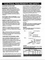
Fig. 1 shows a three-pronged electrical plug and
receptacle that has a grounding conductor. If a properly
grounded receptacle is not available, an adapter (Fig. 2)
can be used to temporarily connect this plug to a twocontact grounded receptacle. The adapter (Fig. 2) has a
rigid lug extending from it that MUST be connected to a
permanent earth ground, such as a properly grounded
receptacle box.
DO NOT MODIFY THE PLUG PROVIDED. If it will not
fit the receptacle, have the proper receptacle installed
by a qualified electrician.
IMPROPER CONNECTION of the equipment grounding
conductor can result in risk of electric shock. The
conductor with the green insulation (with or without
yellow stripes) is the equipment grounding conductor.
If repair or replacement of the electrical cord or plug is
necessary, do not connect the equipment grounding
conductor to a live terminal.
CAUTION
In all cases, make certain the receptacle is properly
grounded. If you are not sure, have a qualified
electrician check the receptacle.
CAUTION
This tool is for indoor use only. Do not expose to
rain or use in damp locations.
CHECK with a qualified electrician or service person
if you do not completely understand the grounding
instructions, or if you are not certain the tool is properly
grounded.
Fig. 1
USE only three-wire extension cords that have threepronged grounding plugs with three-pole receptacles
that accept the tool's plug. Repair or replace damaged
or worn cords immediately.
GUIDELINES
FOR EXTENSION
Three-Pronged
_ng
_
CORDS
Plug
Prong
Properly Grounded
Three-Pronged
Receptacle
Fig. 2
USE THE PROPER EXTENSION CORD. Make sure
GroundingLug
/ I L| |-_ II Make surethis is
_':_
I _
connected to a
._.1-(_
II known ground.
your extension cord is in good condition. Use an
extension cord heavy enough to carry the current your
product will draw. An undersized cord will cause a drop
in line voltage resulting in loss of power,
overheating and burning out of the motor. The table on
the right shows the correct size to use depending on
cord length and nameplate ampere rating. If in doubt,
use the next heavier gauge. The smaller the gauge
number, tl_e heavier the cord.
wo-Pron e,
Adapter''--_
Receptacle
CAUTION
This tool must be grounded while in use to protect
the operator from electric shock.
Make sure your extension cord is properly wired and in
good condition. Always replace a damaged extension
cord or have it repaired by a qualified technician before
(When usin_ 120 voltsonly)
Total len_lth of Cord
Ampere Rating
100ft. 150ft.
More Than
Not More Than 25ft. 50ft.
18
16
16
14
0
6
18
16
14
12
6
10
using it. Protect your extension cords from sharp
objects, excessive heat and damp or wet areas.
Use a separate electrical circuit for your tool. This circuit
must not be less than #12 wire with a 20 A time-lag fuse
!_ 7
16
16
14
12
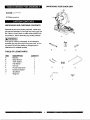
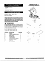
UNPACKING
YOUR CHOP SAW
#2 Phillips screwdriver
UNPACKING
AND CHECKING
CONTENTS
Separate all parts from packing materials. Check each
part with the illustration on the right side of the page and
the 'q'able of Loose Parts" to make certain all items are
accounted for, before discarding any packing material.
I,A
WARNING
A
I
If any part is missing or damaged, do not attempt to
assemble the chop saw, plug in the power cord, or turn
the switch ON until the missing or damaged part is
obtained and is installed correctly.
B
TABLE
C
D
OF LOOSE PARTS
ITEM
A
B
DESCRIPTION
Machine
Blade Wrench
QUANTITY
1
1
C
D
"AAA" Battery
Flat Washer
2
2
E
F
G
Hex Key
Round Head Screw
Extension Bracket
2
2
1
H
I
Stop Block
Wing Nut
1
1
F
G
H
..........
!
I
,,
p
, ,L,
8
IRllgllllBml'
.._i,-=i
...........
"_"
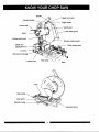
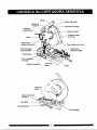
Handle
Trigger lock button
Carrying handle
Trigger switch
Power cord
Spindle lock
Lower blade guard
Motor
Locking chain hook
Abrasive cutting wheel
Depth stop
Quick-release lever
adjustment bolt
Lock nut
Wrench and storage
Locking chain
Vise clamp
Base
Vise
Vise handle
Laser guide
Extension wing
Adjustable fence
9 !111
I,_ WARNING
Fig. B
J
Fig. C
Fig. D
Never connect the plug to the power source outlet until
all installations and adjustments are completed and you
have read and understood the safety and operational
instructions.
l_,
WARNING
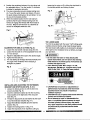
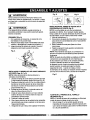
ADJUSTING THE CUTTING DEPTH STOP BOLT
(Fig. E)
]
Failure to unplug your saw could result in accidental
starting causing possible serious personal injury.
NOTE: The cutting depth was adjusted properly at the
factory. If adjustments are needed, be careful not to
adjust the depth stop bolt too deep as the cutting wheel
may contact the base.
1. Loosen the Iocknut (1),
2. Turn the depth stop bolt (2) out to decrease the
cutting depth or in to increase the cutting depth.
3. Lower the cutting head to check if the wheel
contacts the base.
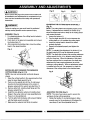
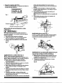
ASSEMBLY (Fig. A)
1. For shipping purposes, the cutting head is locked in
the down position,
2. Push down on the upper arm assembly and unhook
the Iockng chain (1).
3. After removing the locking chain, move the cutting
head to the upward position.
4.
Fig. A
Repeat until adjusted properly and tighten the
Iocknut.
NOTE: To maintain this adjustment, the Iocknut (1) on
the depth stop bolt (2) must be tightened securely.
NOTE: The depth stop is factory set providing maximum
cutting capacity for the 14 in. abrasive wheel provided
with your chop saw. When the diameter of the wheel
has been reduced due to normal wear, the depth stop
adjustment bolt may require adjustment to provide
maximum cutting capacity. When a replacement wheel
is installed onto the unit, it is necessary to check the
clearance of the cutting wheel to the machine base,
INSTALLING AND CHANGING THE ABRASIVE
Fig. E
CUTTING WHEEL (Fig. B, C, D)
NOTE: Use only recommended reinforced abrasive
wheels.
1.
Raise the cutting handle to the upward position then
2,
raise the lower blade guard (Fig. B),
Push in on the spindle lock (2-Fig. A) and loosen
the arbor bolt counterclockwise in the center of
3.
abrasive wheel with the wrench provided (Fig. C).
Remove arbor bolt, outside wheel flange and the
4.
abrasive wheel (Fig. C).
Install the new abrasive wheel and outside wheel
ADJUSTING THE VISE (Fig. F)
NOTE: The vise of your saw is used to secure the
workpiece during cutting operations.
1. Rotate the handle (1) counterclockwise to allow
flange in the same order as it was assembled prior.
5. Press in on the spindle lock.
6. Turn the arbor bolt clockwise until sung and tighten
7.
with the blade wrench provided,
Make sure the wheel is held firmly in position.
enough room for the workpiece to fit between the
vise clamp (2) and the adjustable fence (3),
10
2.
Position the workpiece between the vise clamp and
the adjustable fence. Turn the handle (1) clockwise
to clamp the workpiece securely.
3. The vise incorporates a quick release locking lever
(4). To use the quick release vise feature, lift up on
the quick release locking lever (4) and slide in or out
the vise to the desired position.
4. When the desired location for the vise clamp is
achieved, flip the quick release locking lever (4)
forward to engage the threads with the threads of
the vise. Begin to turn the lever (1) clockwise to
secure the workpiece within the vise.
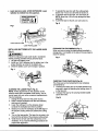
loosening the wing nut (3), sliding the stop block to
the desired position and locking in place.
Fig. H
3
2
1
Fig. H-1
Fig. F
6
THE LASER GUIDE
Your tool is equipped with the Laser Trac_ cutting guide,
a battery powered device using Class Ilia laser beams.
The laser beams will enable you to preview the abrasive
ADJUSTING FOR ANGLE CUTTING (Fig. G )
1. Loosen the vise handle and back away the vise.
2. Loosen the two bolts (1) of the adjustable fence with
a 17 mm wrench.
wheel path on the workpiece to be cut before you begin
your operation.
I,_ WARNING
3. Adjust the adjustable fence (2) to the desired angle.
4. Tighten the two bolts (1).
5. The vise clamp (3) will align itself automatically with
the angle of the workpiece when clamping a
workpiece in position.
Fig. G
I
• Do not stare into beam or view directly with
optical instruments. Do not remove the warning
label affixed to the wheel guard. Avoid direct eye
contact with light source.
• Laser Warning Label: Max. Output < 5 mW,
Wavelength: 630660 nm, Complies with 21CFR
1040.10 and 1040. 11 Class Ilia laser product.
1
LASER
RADIATION-AVOID
DIRECT
EYE EXPOSURE
Max.0utput <5 mWWavelength: 630..660 nm
Complieswith 21CFR 1040.10and1040.11
Clau Ilia Laser Product
INSTALLING AND ADJUSTING THE EXTENSION
BRACKET AND STOP BLOCK (FIG. H, H-l):
• CAUTION-Use of controls or adjustments or
performance of procedures other than those
specified herein may result in hazardous
radiation exposure.
• CAUTION-The use of optical instruments with this
product will increase eye hazard.
• Do not attempt to repair or disassemble the
1. Loosen the locking screw (1) with the 5ram hex
wrench provided (Fig. H).
2. Insert the extension bracket (2) into the mounting
holes located on the right side of the chop saw
base (Fig. H).
3. Thread the stop screw (5) and washer (6) into each
end of the extension bracket (Fig. H-l).
4. Adjust the extension bracket (2) to the desired
laser. If unqualified persons attempt to repair
this laser product, serious injury may result.
position (Fig. H).
5. Tighten the locking screw (1) (Fig. H-l).
6. Adjust the stop block (4) for repetitive cutting by
Any repair required on this laser product should
be performed by authorized service center
personnel.
L
I
_ ii --_ii
;
11
LaserApertureLabel:AVOIDEXPOSURE:
Laser
radiationis emittedfromthis aperture.
7.
To parallel the laser line with the cutting wheel,
loosen only 1/2 turn at a time the set screw (1).
8. To shift the laser to the right, turn set screw (3).
NOTE: More than 1/8 turn may damage the laser
assembly.
9. To shift the laser to the left, turn set screw (4).
AVOIDEXPOSURE
Laser
radiation
h
•
is emitted from/:_._
•
thisaperture_L._._ II
Fig. K
Fig. I
Laser Aperture Label
Laser Warning Label
INSTALLING
STORAGE FOR THE WRENCH (Fig. L)
When you are not using the blade wrench provided, a
storage clip (1) is located on the side of the saw base to
store the wrench.
BATI'ERIES INTO THE LASER GUIDE
(Fig. J)
I,_ WARNING
I
Failure to unplug your saw could result in accidental
starting causing possible serious personal injury.
1. Lift open the battery cover.
2. Install two =AAA" batteries into the battery box in the
proper direction as noted in the battery box.
3. Close the battery cover until it snaps in position.
Fig. L
Fig. J
CARRYING YOUR CHOP SAW (Fig. M)
The chop saw can be transported to any workplace
conveniently by:
1. Lowering the cutting arm to its lowest position and
securing in place by attaching the locking chain (1)
to the hook (2).
2. Transport the saw by the carrying handle located
above the motor.
ALIGNING THE LASER TRAC e (Fig. K)
NOTE: All the adjustments for the operation of this
machine have been completed at the factory. Due to
normal wear and use, some occasional readjustments
may be necessary.
1. Unplug the chop saw from the power source.
2. Place a sample workpiece into the vise assembly
and secure in position,
3. Lower the cutting arm so the abrasive wheel
contacts the workpiece and hold in position.
4. Scribe a line onto the workpiece at the left edge of
the abrasive cutting wheel and release the cutting
arm.
5. Turn on the laser guide. The laser line is setup to be
flush with the left side of the abrasive cutting wheel.
6. Verify the line is flush with the scribed line on the
workpiece. If not, read the following procedures for
proper laser alignment.
III
I
Fig. M
1
12
IIIII
I,_ WARNING
CUTTING A WORKPIECE
J
Never connect the plug to the power source outlet until
all installations and adjustments are completed and you
have read and understood the safety and operational
instructions.
ON/OFF SWITCH (Fig. N)
The ON/OFF trigger switch (1) is located on the handle
position of the cutting arm.
1. Tum the chop saw ON by depressing the trigger
switch (1).
2. To turn off, release the trigger switch.
LOCK-ON BUTTON (Fig. N)
1. To engage the lock-on feature, depress the trigger
switch (1), and simultaneously push in the lock-on
the button (2) located on the side of the handle,
then release the tool to continuously run.
2. To release the lock on feature, depress the trigger
switch and release.
I,A WARNING
I_
I
•
•
Never perform any cutting operation freehand
(without placing workpiece in the vise).
Material will get hot during cutting operations. Keep
hands off of metal being cut to avoid serious
personal injury.
•
Do not touch the cut material until it cools or you can
be burned.
•
Keep your hands a safe distance from the blade (at
least 3 inches from the cutting wheel).
Inspect the abrasive cutting wheel before every
operation. Check for cracks, chipping and correct
speed ratings on the cutting wheel.
•
1. Place the workpiece flat on the machine base.
2. Firmly secure the material to be cut using the
J
If you have the lock on feature engaged during use and
the power is disconnected to the saw, disengage the
lock-on feature immediately.
IA WARNING
I
To avoid accidental start-up of your chop saw, always
make sure the switch is OFF and the lock-on feature is
disengaged before connecting to power source. Failure
to heed this warning could result in seriour personal
injury.
NOTE: Make the ON/OFF switch childproof. Insert a
padlock, or chain with padlock, through the holes (3) in
the trigger switch, locking the tool's switch, preventing
children and other unauthorized users from turning the
machine on.
machine's vice clamp assembly.
3. Turn on the Laser Trac ®cutting guide.
4. Align the cutting line on theworkpiece with the laser
guide. The left side of the workpiece to be cut will
be the finished piece as the cutting wheel will pass
immediately to the right of the Laser Trac ®cutting
5.
guide.
When cutting long workpieces, support the opposite
end of the material with a roller stand or with a work
surface level with the machine.
6. Before turning the machine on, perform a dry run
of the cutting operation to verify no problems will
occur when the cut is made.
7. Turn on the machine by depressing the trigger
switch. Allow a few seconds for the wheel to build
8.
Fig. N
WARNING
Failure to heed to the safety rules could result in serious
personal injury:
• To avoid serious personal injury, always make sure
the adjustable fence is secured in position.
3
2
up to full speed before letting it come into contact
with the workpiece.
Once the motor has reached full speed, slowly lower
the handle of the cutting arm until the cutting wheel
contacts the workpiece. Continue to use steady
even pressure to obtain a uniform cut through the
workpiece. Do not force the wheel into the
workpiece.
9. When the cut is complete, release the trigger switch
and allow the wheel to stop rotating BEFORE raising
the cutting arm out of the workpiece.
13 _
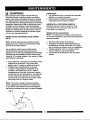
[,_
WARNING
J
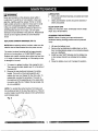
Never put lubricants on the abrasive wheel while it
is spinning. To avoid fire or toxic reaction, never use
gasoline, naphtha acetone, lacquer thinner or similar
highly volatile solvents to clean the chop saw.To avoid
injury from unexpected starting or electrical shock,
unplug the power cord before working on the tool. To
avoid electrical shock, fire or injury, use only parts
identical to those identified in the parts list. Reassemble
exactly as the original assembly to avoid electrical
shock.
REPLACING CARBON BRUSHES (FIG. O)
NOTE:Before replacing carbon brushes, make sure the
machine has be disconnected from the power source.
The carbon brushes furnished will last approximately
50 hours of running time, or 10,000 ON/OFF cycles.
Replace both carbon brushes when either has less than
1/_in. length of carbon remaining, or if the spring or wire
is damaged or burned.
,
,
To inspect or replace brushes, first unplug the tool.
Then remove the black plastic cap (1) on the side of
the motor (2).
Remove the cap cautiously because it is springloaded. Then pull out the brush assembly and
replace the new one. Repeat for the other side. To
reassemble, reverse the procedure. The ears on
the metal end of the assembly go in the same slots
the carbon part fits into. Tighten the cap snugly, but
do not overtighten.
NOTE: To reinstall the same brushes, first make sure
the brushes go back in the way they came out. This will
avoid a break-in period that reduces motor performance
and increases wear.
Fig. O
1
LUBRICATION
•
•
Motor and cutterhead bearings are sealed and need
no lubrication.
Gears and elevation screws should be cleaned of
debris and grease.
CLEAN CHOP SAW
Keep your chop saw clean. Continually remove metal
chips, dust, dirt and debris.
CHANGING THE BATTERIES
NOTE: Failure to unplug your saw could result in
accidental starting causing possible serious personal
injury.
1. Lift open the battery cover.
2. Remove the two batteries by sliding them out from
their mounting braces using a non-conductive device
3.
4.
such as a toothpick.
Install two new "AAA" batteries into the battery box
in their proper direction as indicated in the battery
box.
Close the battery cover until it snaps into position.
I,A
WARNING
I
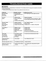
To avoid injury from an accidental start, tum the switch OFF and always remove the plug from the power source before
making any adjustments.
• Consult your local Sears Service Center if for any reason the motor will not run.
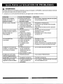
SYMPTOM
POSSIBLE CAUSES
CORRECTIVE ACTION
Chop saw wheel
hits base or
work surface.
1 .The cutting depth
adjustment bolt is set too
deep.
1. See "Adjusting the Cutting Depth Stop Bolt".
Cut is not
1. Defective wheel.
square.
2. Work not positioned
properly.
3. Excessive wheel pressure.
1. Replace immediately.
2. Check adjustable fence for squareness to blade..
3. Lessen wheel pressure during cutting operation.
Chop saw wheel
binds, jams,
1. Improper operation.
2. Dull chop saw wheel.
burns workpiece.
Rough cuts
3. Improper chop saw wheel. 3. Replace with 14 in. abrasive cutting wheel.
Tool vibrates or
shakes.
1. Wheel not round.
2. Wheel damaged.
3. Wheel loose.
4. Machine is not secure.
1. Replace wheel.
2. Replace wheel.
5. Other.
5. Consult your local Sears Service Center.
Power head
1. Pivot spring or guard
1. Consult your local Sears Service Center.
won't fully rise
or lower guard
won't fully close.
spring not replaced
properly after service.
2. Part failure.
Cutting head hard to
3ulVpush down.
1. Lube needed.
1. See "Maintenance"
The laser guide will not turn on.
1. The batteries are drained.
1. Replace batteries.
Cutting wheel does not cut
through workpiece.
1. Depth stop bolt setting is
incorrect.
:1. See "Adjusting the Cutting Depth Stop Bolt"
section.
1. See "Operation" section.
2. Replace wheel.
3. Tighten arbor bolt.
4. Mount tool to worksurface.
section.
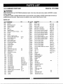
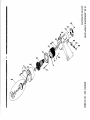
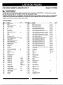
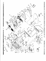
14 IN. ABRASIVE
I,_, WARNING
CHOP SAW
Model No. 137.212890
]
When servicing use only CRAFTSMAN replacement parts. Use of any other parts many create a HAZARD or cause
product damage.
Any attempt to repair or replace electrical parts on this Chop Saw may create a HAZARD unless repair is done by a
qualified service technician. Repair service is available at your nearest Sears Service Center.
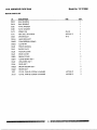
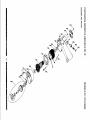
PARTS LIST
I.D. NO.
DESCRIPTION
I.D. NO.
DESCRIPTION
OF5U
VISE CLAMP
SIZE
QTY
1
OJEF
C-RING
SIZE
OF5W
SUPPORT
1
OJPV
HEX. HD. BOLT
OF5Z
QUICK
1
OJPX
OF60
PLUNGER HOUSING
1
0F67
LOCKING
1
OF6C
FOOT
30JUW
OF6T
SIDE PLATE
1
OK2E
HEX. SOC. HD. CAP BOLT
HEX. SOC. HD. CAP SCREW
0F76
TORSION
1
0K35
CR. RE. PAN HD. SCREW & WASHER
0F79
UPPER BLADE GUARD
1
0K37
OF7A
COLLAR
1
OF7C
FLANGE
OF7D
COLLAR
OF7H
ABRASIVE
OF7L
HEX. HD. SCREW AND
OF7X
LOWER BLADE GUARD
OF9Q
NYLON
WASHER
OF9W
MOTOR
HANDLE
OF9X
QTY
2
M8* 1.25-70
1
HEX. HD. BOLT
M 1O* 1.5-20
2
OJQ7
HEX. HD. BOLT
M8"1.25-25
2
OJUP
HEX. SOC. HD. CAP BOLT
M6* 1.0-35
M8"1.25-25
1
2
M8* 1.25-40
2
M5"0.8-25
1
CR.RE. PAN HD. SCREW & WASHER
M5"0.8-16
1
OK3H
CR. RE. PAN HD. SCREW & WASHER
M6"1.0-12
1
2
0K41
CR. RE. PAN HD. SCREW & WASHER
M6* 1.0.80
4
1
0K47
CR. RE. PAN HD. SCREW & WASHER
M6* 1.0.20
I
1
0K75
CR. RE. TRUSS HD. SCREW
M6"1.0-12
2
M10"1.5
1
OK7N
CR. RE. ROUND
M6* 1.0-30
I
#AW
1
OK9E
CR. RE. TRUSS HD. TAPPING
SCREW
M4"16-12
2
2
OK9L
CR. RE. TRUSS HD. TAPPING
SCREW
M4"16-I0
2
1
OKDN
CR. RE. PAN HD. SCREW
M5"0.8-25
8
REAR LOWER GUARD
1
OKDT
CR. RE. PAN HD. SCREW
M6* 1.0-8
2
OFAO
LOCKING
1
OKDU
CR. RE. PAN HD. SCREW
M6"1.0-12
4
OFA I
CLAMP-CORD
1
OKE3
CR. RE. PAN HD. SCREW
M8* 1.25-35
3
OFAB
TORSION
1
OKFG
CR. RE. PAN HD. SCREW
M5"0.8-12
I
OFAC
CLEAR PANEL
1
OKFS
CR. RE. PAN HD. SCREW
M8"I
.25-16
I
OFAF
SHAFT-PIVOT
1
OKKL
CR. RE. PAN HD. ROUND
M6"I
.0-16
OFAG
METAL LEG
1
OKMR
HEX. NUT
M5"0.8
OFAN
CENTER SHAFT SET PLATE
#06
1
OKMY
HEX. NUT
M8"I .25 T=6.5
I
OFAQ
CENTER SHAFT SET PLATE
#06
1
OKQW
LOCK
M5"0.8
I
OFAS
CENTER SHAFT
1
OKRO
NUT
M12"1.75
OFAT
CENTER SHAFT WASHER
2
OKR3
LOCK NUT
M6* 1.0 T=6
2
OFLJ
PLUNGER
2
OQJA
MOTOR
#AW
1
OHFW
BOLT CLAMP
1
OQQ 1
GUARD-CORD
1
OJ3K
HEX. WRENCH
1
OZOP
EXTENSION
1
OJ3Q
HEX. WRENCH
1
OZOQ
WRENCH
OJ4M
FLAT WASHER
(D12"21-I
1
OZOX
POWER
OJ4Q
FLAT WASHER •
(D 12*21-2
FLAT WASHER
(D6"18-I
28N2
290M
BAT[ERY
OJ4U
1
2
OJ50
FLAT WASHER
(D6 3* 15-4
1
29PW
LASER ASS'Y
OJ5W
FLAT WASHER
(D 18. I *26-0.3
1
29V0
VISE ASS'Y
2AGE
HEX. WRENCH
RELEASE LEVER
#06
CHAIN
SPRING
CUTI'ING
HOUSING
#AW
WHEEL
WASHER
CHAIN
ASS'Y
HOOK
SPRING
.5
"
WASHER
NUT
1
3/8"29/32-5/64
2
2BOW
OPERATOR'S
OJ7T
FLAT WASHER
I/4"29/32-I/I
1
2BX6
RETAINING
CLIP
0J93
SPRING WASHER
m10
2
2BZZ
WARNING
LABEL
0J94
SPRING WASHER
m8
3
2C01
LABEL
0J9T
SPRING WASHER
m5/I
2
2C02
TRADE-MARK
0JAF
EXTERNAL TOOTH
m5
1
2C03
LASER LABEL
OJB5
WAVE
WW-18
I
._C7Z
BASE
OJCV
SPRING PIN
I
._JVN
ADJUSTABLE
FENCE
OJE7
C-RING
I
2JZG
STOP BLOCK
ASS'Y
OJEE
C-RING
I
31MF
TRIGGER SWITCH ASS'Y
I II i
16
1
1
3/I 6"15/32-I/32
II1_1
'
I
1
#06
FLAT WASHER
_n
T=12
1
LABEL
FLAT WASHER
WASHER
T=5
9
1
CABLE
OJ7K
LOCK WASHER
I
T=4
1
HOLDER
OJ6W
6
NECK SCREW
BRACKET
1
6
HD. SCREW
,
1
MANUAL
2
LABEL
#06
#06
Z
OKKL
orgq e
/
OJ4M
._I. ,,o
OFTL
>
OFTH
<
29V0
i
0
\
"-4
OKDN8
o_P_
\
0F87
I
r-
L
2AG
_.A
O0
(D
0
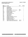
14 IN. ABRASIVE
Model No. 137.212890
CHOP SAW
MOTOR PARTS LIST
kO.
DESCRIPTION
0HUZ
BALL BEARING
SIZE
QTY
1
0HVU
BALL BEARING
1
0JB6
WAVE WASHER
1
0JB8
WAVE WASHER
0JCF
SPRING PIN
m4-30
1
0JYZ
HEX. SOC. SETSCREW
M5"0.8-12
2
0KSN
STRAIN RELIEF
ml0
1
0KWA
LEAD WIRE ASS'Y
1
0QGR
COMPRESSION SPRING
1
0QGS
CLEVIS PIN
1
0Q J0
FRONT HOUSING
1
0Q J1
BAFFLEPLATE
1
0(2J6
MOTOR COVER
1
0(2 J7
REAR COVER
1
0C R0
BRUSHCOVER
2
0C HY
CUTTERSHAFT ASS'Y
1
0C J2
ARMATURE ASS'Y
1
0G J4
FIELDASS'Y
1
0QQS
BRUSH HOLDER ASS'Y
2
1
0QQT
BRUSHASS'Y
129P
CR. RE. PAN HD. SCREW & WASHER
M5"0.8-75
2
2
21CH
CR. RE. PAN HD. SCREW & WASHER
M5"0.8-10
2
o
cn
..,u
_3
OJCF
0
€3
m
r-
Z
0
--.L
CA)
F,,
--.L
0
Your Home
For expert troubleshooting
and home solutions advice:
manage home
www.managemyhome.com
For repair - in your home - of all major brand appliances,
lawn and garden equipment, or heating and cooling systems,
no matter who made it, no matter who sold it!
For the replacement parts, accessories and
owner's manuals that you need to do-it-yourself.
For Sears professional installation of home appliances
and items like garage door openers and water heaters.
1-800-4-MY-HOME
Call anytime,
®
(1-800-469-4663)
day or night (U.S.A.
_.sears.com
and Canada)
_.sears.ca
Our Home
For repair of carry-in items like vacuums, lawn equipment,
and electronics, call anytime for the location of your nearest
Sears Parts & Repair Service Center
1-800-488-1222
(U.S.A.)
1-800-469-4663
www.sears.com
To purchase a protection
1-800-827-6655
www.sears.ca
agreement
(U.S.A.)
Parapedir
servicio de reparaci6n
a domicilio,
y para ordenar piezas:
1-888-SU-HOGAR
(Canada)
on a product serviced by Sears:
1-800-361-6665
(Canada)
Au Canada pour service
®
1-800-LE-FOYER
en fran?ais:
.c
(1-800-533-6937)
www.sears.ca
(1-888-784-6427)
Se__
® Registered Trademark / TM Trademark ! SMService Mark of Sears Brands, LLC
® Mama Registrada /
Marca de Fdbdca / SM Mama de Servicio de Sears Brands, LLC
=c Marque de commerce
/
MD
Marque d_pos_e
de Sears Brands, LLC
© Sears Brands, LLC
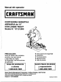
Manual del operador
CORTADORA SENSITIVA
ABRASIVA de 14"
CON LASER TRAC ®
Modelo
N.° 137.212890
PRECAUCION:
•
•
•
•
•
Antes de utilizar esta cortadora
sensitiva, lea este manual
y siga todas las reglas
de seguridad y las instrucciones
de operacibn
Linea
de asistencia
Centro
a cliente
Sears
de piezas
y reparaciones
1-800-488-1222
1-800-843-1682
Sears Brands Management
Instrucciones de seguridad
Instalacibn
Funcionamiento
Mantenimiento
Lista de piezas
Corporation
Hoffman
Estates, IL60179
USA
Vea la linea completa de productos Craftsman e en craftsman.com
IPulse en el enlace Craftsman Club • y 0nase hoy mismo!
Pieza N. ° 137212890001
Impreso en China
SECClON
PAGINA
Garantfa .........................................................................
2
Especificaciones del producto ........................................ 2
Seguridad en el manejo de herramientas el6ctdcas ...... 3
Seguridad en el manejo de la cortadora sensitiva ......... 4
Requisitos el_ctricos y seguridad .................................. 7Contenido de la caja ....................................................
8
GARANT|A
SECClON
PAGINA
Conozca su cortadora sensitiva ..................... 9
Ensamble y ajustes .....................................
10
Funcionamiento.......................................
13
"Mantenimiento ........................................
14
Gufa para la soluciOnde problemas............... 15
Lista de partes ................................................ 16
TOTAL DE CRAFTSMAN
Si este producto Craftsman presenta una falla debido a un defecto del fabdcante en los materiales o la mano de
obra dentro del perfodo de un a_o a partir de la fecha de compra, devu61valo a cualquier tienda Sears u Centro de
servicio Sears para repuestos y reparaciones, u otro punto de distribuci6 n Craftsman en los Estados Unidos para
la reparaci6 n gratuita (o reemplazo si no es posible efectuar la reparaci6 n).
Esta garantfa no incluye las partes fungibles tales como las hojas de la sierra, las cuales pueden desgastarse con
el uso normal durante el perfodo de garantfa. Esta garantfa no incluye partes fungibles, tales como bombillas,
baterfas, brocas u hojas. Esta garantfa le da derechos legales especfficos; usted podda tener otros derechos que
varfan de un estado a otro.
Sears, Roebuck and Co., Hoffman Estates, IL 60179
ADVERTENCIA
I
El polvo producldo por las herramlentas eldctrlcas contlene sustancias qu|mlcas que el estado de Callfornla
reconoce como causantes de c=tncer, malformaclones cong6nitas u otros dafios reproductlvos. Algunos
ejemplos de estos quimlcos son:
•
Plomo de las plnturas a base de plomo
•
Sglce cristallna proveniente de los ladrlllos, del cemento y de otros productos de albafiller|a
• Arsdnico y el cromo provenlente de las maderas tratadas con qufmlcos
El rlesgo que Impllcan estas exposlclones var|a segdn la frecuencia con qua se realice este tlpo de trabajo.
Para reducir la exposlcl6n a estos qu|mlcos, trabaje en un drea blen ventllada y utillce un equlpo de segurldad
aprobado, como mdscaras contra polvo especlalmente disefiadas para filtrar part|culas mlcrosc6plcas.
MOTOR
HP (M_ximo desarrollado) .......................
3.5
Ala de extension ..............................
Si
Tipo ..........................................................
Universal
Guia I-_ser........................................
S{
Amperios .................................................
15
Altura mdxima de corte ...................
5" (a 2" de ancho)
Tama_o del drbol de la hoja .....................
1"
Ancho mdximo de corte ...................
7" (a 3" de alto)
Voltaj.e .....................................................
Hz ............................................................
120
60
Angulo de la prensa de tomillo de ...
0° a 45 °
R. P. M. (sin carga) ................. .................
3300
Tamar_o de la rueda ................................
14"
[_,
ADVERTENClA
]
Para evitar problemas eidctricos, rlesgos de incendio o dafios en la cortadora sensitiva, utilice una
protecci6n de circuito adecuada.
Esta cortadora sensitiva estd fabricada para funcionar con un voltaje de 110 V a 120 V. Debe estar
conectada a un fusible de retardo o a un interruptor de circuitos de 110 a 120 V y de 15 A. 1)ara evitar
descargas o incendios, reemplace el cable el6ctrico inmedlatamente si estd desgastado, cortado
o dafiado de alguna manera.
Antes de utilizar la cortadora sensitiva, es imprescindible que lea y entlenda estas reglas de seguridad.
Si no sigue estas reglas, puede sufrlr lesiones graves o dafiar la herramienta.
I'll 2
2011/07
:_,,_
ADVERTENCIA
J
Antes de utilizar la cortadora sensitiva, es imprescindible que lea y entlenda estas reglas de segurldad.
Si no sigue estas reglas, puede sufrir lesiones graves o da_ar la herramienta el_ctrica.
La seguridad es una combinaci6n de sentido com_n,
precauci6n y conocimiento del manejo de la herramienta
el_ctdca. Para evitar errores que pueden ocasionarle
lesiones graves, no enchufe la herramienta hasta haber
lefdo y entendido Io siguiente:
13. UTILICE UNICAMENTE LOS ACCESORIOS
RECOMENDADOS. Consulte el Manual del
operador para hallar los accesorios recomendados.
La utilizaci6n de los accesodos inapropiados puede
ocasionarle lesiones o dafiar la herramienta. ,
1. LEAy familiadcese con todo el Manual del operador.
APRENDA todo Io relacionado con la utilizaci6n, las
limitaciones y los posibles riesgos de la herramienta.
14. EXTRAIGA I_AS LLAVES DE AJUSTE Y I_AS
LLAVES INGLESAS. AcostOmbrese a revisar la
herramienta y a vet que se extraigan de ella las Ilaves
de ajuste antes de ENCENDERLA.
2. [_ll
ADVERTENCIA
J
Busque este simbolo, que indica importantes
precauciones de seguridad. Significa
PRECAUClON. ESTE ALERTA, SU SEGURIDAD
ESTA EN JUEGO.
.
4.
.
.
NO UTILICE LA HERRAMIENTA EN AMBIENTES
PELIGROSOS. No utilice herramientas el_'tdcas en
lugares h6medos o mojados ni las exponga a la Iluvia.
Mantenga bien iluminada el _rea de trabajo.
NO utilice herramientas el_ctdcas en presencia
de Ifquidos o gases inflamables.
MANTENGA LIMPIA EL AREA DE TRABAJO.
Las _reas y los bancos de trabajo desordenados
provocan accidentes.
MANTENGA ALEJADOS A LOS NII_IOS.Todos los
visitantes deben permanecer a una distancia segura
del drea de trabajo.
7. NO FUERCE LA HERRAMIENTA. De esta manera
realizar_ su trabajo mejor, con m_s seguridad y a la
velocidad para la que estd diseSada la herramienta.
8.
.
UTILICE LA HERRAMIENTA ADECUADA.
No intente hacer que la herramienta o los
acoplamientos realicen trabajos para los cuales
no fueron diseSados.
USE LAS PRENDAS APROPIADAS. NO use ropa
suelta, guantes, co rbatas, anillos, brazaletes ni otras
alhajas que puedan atascarse en las piezas m6viles.
Se recOmienda usar calzado antideslizante. Use una
protecci6n para cubdr y contener el cabello largo.
10. USE UNA MASCARA FACIAL O UNA
MASCARILLA CONTRA EL POLVO. Los trabajos
de aserrado, de corte y de lijado producen polvo.
11. DESCONECTE LAS HERRAMIENTAS antes
de realizar el mantenimiento y de cambiar accesorios
como hojas, cortadores, etc.
12. REDUZCA EL RIESGO DE QUE SE PRODUZCA
UN ARRANQUE NO DESEADO. Asegurese de que
el interruptorestd en la posici6n de APAGADO antes
de enchufar la herramienta en la fuente de energia
el_ctdca.
15. NUNCA DEJE DESATENDIDA UNA
HERRAMIENTA. CORTE LA ENERGIA ELECTRICA.
No deje la herramienta hasta que se detenga por
completo,
16. NUNCA SE PARE ENCIMA DE LA HERRAMIENTA.
Dar vuelta la herramienta 0 tocar accidentalmente
la hoja de corte puede ocasionade lesiones graves.
17. NO FUERCE LA POSTURA. Mantenga el equilibdo
y el apoyo correcto de los pies en todo momento.
18. MANTENGA LAS HERRAMIENTAS CON CUIDADO.
Mantenga las herramientas afiladas y Ifmpielas para
que su funcionamiento sea mejor y m_s seguro. Siga
las instruccionespara la lubdcacibny el reemplazo
de los accesorios.
19. CoMPRUEBE QUE NO HAYA PIEZAS DAf;IADAS
NI FLOJAS. Antes de seguir utilizandola herramienta,
debe revisarcuidadosamente los protectoreso las
otras piezas que puedan estar daSadas para
asegurarse de que la herramienta funcionard
y realizar_ su trabajo correctamente. Asegerese
de que las piezas m6viles estdn alineadas, y de que
no estdn atascadas; controle el montaje y verifique
que no existan otras condicionesque puedan afectar
la correcta utilizaci6n. Los protectoresu otras piezas
que estdn flojos o daSados deben ajustarse, repararse
o reemplazarse debidamente.
20. EVITE QUE SUS HERRA_IENTAS PUEDAN SER
UTLIZADOS POR LOS NINOS mediante candados
o interruptoresmaestros, o mediante la extraccibn de
las Ilaves de encendido.
21. NO trabaje con la herramienta si se halla bajo el efecto
de las drogas, el alcohol o alguna medicaci6n que
pueda afectar su capacidad para utilizar la herramienta
apropiadamente.
22. USE SIEMPRE PROTECCION PARA LOS OJOS.
Cualquier herramienta el_ctdca puede despedir
y hacer que se introduzcan en sus ojos objetos
extraSos que pueden ocasionar un daSo permanente.
Use SIEMPRE galas de seguddad (no lentes
comunes) que cumplan con la norma de seguridad
Z87.1 de ANSI. Los lentes comunes sblo tienen
cdstales resistentesa los golpes. NO SON galas
de seguridad.
NOTA: Las gafas o los lentes que no cumplancon
con la norma ANSI Z87.1 pueden ocasionarle lesiorles
(]raves si se romDen.
mL[ ............. ___1
........ __............................
ANTES DE UTILIZAR LA CORTADORA SENSITIVA, ES
IMPRESCINDIBLE QUE LEA Y ENTIENDA ESTAS REGLAS
DE SEGURIDAD.
Ijl_
ADVERTENCIA
• Para evitar lesiones por descargas el_,_tricas,
asegSrese de que sus dedos no toquen las
espigas meta.licas del enchufe cuando conecte
o desconecte la cortadora sensitiva.
• APAGUE y desconecte la cortadora sensitiva antes
de transportarla a otro lugar. Para evitar lesiones en
la espalda, pida ayuda para realizar el transporte.
• Fije la cortadora sensitiva al piso si tiende
a moverse cuando corte piezas de trabajo largas
y pesadas.
• NO SE PARE frente a la cortadora sensitiva.
No guarde materiales sobre la herramienta
ni cerca de ella. Si se para frente a la herramienta,
puede sufrir lesiones graves.
]
PARA EVITAR ERRORES QUE PODRIAN
OCASIONARLE LESIONES GRAVES O
PERMANENTES, NO ENCHUFE LA CORTADORA
SENSITIVA HASTA COMPLETAR LOS SIGUIENTES
PASOS:
1. Aprenda a utilizar la funcion del interruptor de
ENCENDIDO y APAGADO, det mango de corte
y del protector del disco.
2. Revise y entienda todas las instrucciones de seguridad
y los procedimientos de utilizacion indicados en este
Manual del operador.
3. Revise los m6todos de mantenimiento para esta
cortadora sensitiva.
4. Encuentre y lea todas las etiquetas de advertencia que
se hallan en la cortadora sensitiva:
• Lea el manual antes de utilizar la cortadora
sensitiva.
• Use gafas de seguridad.
• Nunca realice operaciones de corte si no estb.
colocado el protector del disco.
• CORTE el suministro electdco, espere a que
el disco abrasivo se detenga y desconecte el cable
de alimentaci6n de la fuente de energ/a antes
de realizar los ajustes o el mantenimiento.
5. El pemo del arbol y todas las prensas deben ajustarse
antes de realizar cortes.
6. AsegSrese de que la pieza de trabajo y el disco
abrasivo no esten en contacto antes de utilizar
la cortadora sensitiva.
ANTES DE CADA UTILIZACION
1. INSPECCIONE LA CORTADORASENSITIVA:
• Si alguna pieza falta, estb doblada o da_ada
de alguna manera, o si alguna pieza el_,;tdca
no funciona correctamente,APAGUE la cortadora
sensitivay desencht_fela.
• Reemplace las piezas que falten o esten daSadas
antes de utilizar la cortadora sensitiva.
PARA EVITAR LESIONES POR OBSTRUCClONES,
DESLIZAMIENTOS O PIEZAS ARROJADAS
(CONTRAGOLPES):
• Utilice esta cortadora sensitiva unicamente para
cortar materiales ferrosos.
• Evite lesiones por piezas que puede arrojar
la herramienta. Asegurese de que el disco abrasivo
est6 instalado correctamente y de que el pemo del
a.rboleste ajustado.
• Utilice la herramienta adecuada. No haga que
la herramienta realice trabajos para los cuales
no rue disefiada.
.
INSPECCIONE EL AREA DE TRABAJO:
• Mantenga limpia el &tea de trabajo.
• Las _.reas y los bancos de trabajo desordenados
provocanaccidentes. El piso no debe estar
resbaloso por la presencia de cera o aserrin.
• Evite quemaduras u otrosdaSos ocasionados por
el fuego. No utilicela cortadorasensitiva cerca
de Iiquidos, vapores o gases inflamables.
• Antes de utilizarla cortadorasensitiva, quite de
la mesa todos los objetos que no sean necesarios
para guiar la pieza de trabajo hacia la cortadora.
• Evite lesiones. No realice el trazado, el ensamble
ni la instalacionen la cortadora sensitiva.
• Nunca sujete una pieza de trabajo con las manos.
La pieza de trabajo se calentara,mucho al cortarla.
.
CUANDO INSTALE O MUEVA LA cortadora sensitiva:
1. EVITE HACERLO EN AMBIENTES PEUGROSOS:
• Utilice la cortadora sensitiva en interiores,
en un lugar seco,
protegido de la Iluvia y de la humedad.
• Mantenga bien iluminada el a.reade trabajo.
,
PARA EVITAR LESIONES POR MOVIMIENTOS
INESPERADOS DE LA CORTADORA SENSITIVA:
• Ajuste la cortadora sensitivacon pernos o prensas
sobre una supefficie firme y nivelada en la que
haya espacio suficiente para mover la pieza
de trabajo hasta cortarla por completo.
• Ubique la cortadora con las patas niveladas
y no se balancee.
• Ubique la sierra de modo que los operadores y los
transe_ntes permanezcan a una distancia segura
de la cortadora y no est_n en Iinea recta con la hoja
de la herramienta.
,
PLANIFIQUE EL TRABAJO:
• Antes de intentar realizar un trabajo nuevo o poco
comun, planifiquecuidadosamente la posici6nde
las manos. AsegSrese de contar con accesorios,
topes y otros articulos listos para usar. Evite
lesiones por la utilizacion de recomendados.
Utilice unicamente los accesorios recomendados.
USE PRENDAS SEGURAS:
• Planifique c6mo se proteger_ los ojos, las manos,
la cara y los oidos.
• No use prendas sueltas, guantes, corbatas
ni alhajas (anillos, relojes de pulsera). Pueden
atascarse y atraerlo hacia las piezas moviles.
• Use calzado antideslizante.
• Si tiene el cabello largo, ateselo.
• Arremangue hasta arriba del codo las prendas con
mangas largas.
• Los niveles de ruiclovadan ampliamente. Para "
evitar un posibleda_o auditivo, use tapones
o protectorespara los oidos cada vez que utilice
la cortadorasensitiva.
• La cortadora sensitiva puede despedir y hacer que
se introduzcanen sus ojos objetos extra_os que
pueden ocasionar un da_o permanente. Use gafas
de seguridad (no lentes comunes) que cumplan con
las normas CSA. Los lentes comunes s61otienen
cristales resistentesa los golpes.
No son gafas de seguridad.
• Use una mascarilla contra el polvo junto con las
gafas de seguridad durante cada operacion.
.
.
INSPECCIONE LA PIEZA DE TRABAJO:
• Aseg_rese de que no haya clavos ni objetos
extrados en la parte de la pieza de trabajo
que cortard.
PLANIFIQUE EL CORTE:
• No raalice cortes a pulso. Guie la pieza de trabajo
firmemente contra la guia y sobre la superficie
de la mesa. Aseg_rase de que no haya desechos
entre la pieza de trabajo y los soportes de esta.
• Extreme las precauciones con piezas de trabajo
muy grandes, muy peque_as o de forma irregular.
• Utilice soportes adicionales (mesas, caballetes,
bloques) si resulta diffcilsujetar la pieza de trabajo
en la mesa. No utilicea otra persona como soporte
adicional ni para que Io ayude a guiar, sujetar
o empujar la pieza de trabajo.
• No corte mas de una pieza de trabajo cada vez.
• No ENCIENDA la cortadora sensitiva antes de
clespejar todo Io que haya sobre la mesa, excepto
la pieza de trabajo y los dispositivosde soporte
relacionados.
7.
.
EVITE ENCENDIDOS ACClDENTALES:
Asegurese de que el interruptoreste en la posicionde
APAGADO antes de enchufar la cortadora sensitiva
abrasiva a la fuente de energia el_ctdca.
CUANDO LA CORTADORA SENSlTIVA
ESTE FUNClONANDO
[_
ADVERTENCIA
1
NO PERMITA QUE EL HECHO DE ESTAR
FAMILIARIZADO CON LA CORTADORA SENSITIVA
DEBIDO A LA UTILIZACION FRECUENTE DE LA MISMA
LO LLEVE A COMETER UN ERROR POR DESCUIDO.
RECUERDE QUE UN DESCUIDO DE UNA FRACCION
DE SEGUNDO ES SUFICIENTE PARA OCASIONAR
UNA LESION GRAVE.
°
MANTENGA A LOS NII_OSALEJADOS:
• Asegurase de que todos los transeuntes est_n
resguardadosde la herramienta electrica antes
de y clurante la utilizacion.
• Antes de utilizar la herramienta electrica, pruebe
la sierra encendiendola y dejando que permanezca
en movimientodurante algunossegunclos.Si vibra
o hace un ruicloextra,o, detengala inmediatamente.
APAGUE y desenchufe la cortadora sensitiva°
No vuelva a encenclerlahasta que el problema
se haya solucionaclo.
2. NO FUERCE LA HERRAMIENTA:
• Corte solamente una pieza pot vez.
.
ANTES DE LIBERAR MATERIALES ATASCADOS:
• Suelte el interruptorde gatillo.
• Espera a que todas las piezas movilesse detengan.
• Desenchufe la cortadora sensitiva.
4. ANTES DE DEJAR LA CORTADORA SENSlTIVA:
• Suelte el interruptorde gatillo.
• Desenchufe la cortadora sensitiva.
• Haga que el taller sea a prueba de ni_os.
Cierre con Ilave el taller. Desconecte los
interruptoresmaestros.
ADVERTENCIA J
La medida maxima de discos abrasivos que puede
utilizarse en esta cortadora sensitiva es un disco de
14" (356 mm). Nunca utilicediscos tan gruesos que
hagan que el rebordeexterior se enganche con las partes
planas del husillo. Los discos mbs grandes entrar&nen
contacto con los protectorespara discos, mientras que
los mas gruesos evitar_ que el perno los sujete en el
husillo. Cualquiera de estas situaciones puede ocasionar
un accidente serio y tambien ocasionarle graves lesiones
corporales.
[_l_
ADVERTENCIA
I
No intente cortar madera ni materiales de alba_ileria
con esta cortadorasensitiva. Nunca corte magnesio
ni aleaciones de magnesio con esta maquina. Si no
cumple con estas reglas, corre el riesgo de sufrir lesiones
corporales graves. Para evitar que la cortadora sensitiva
se mueva o se voltee mientras usted realiza un corte,
sujetela a en banco o en una superficiede trabajo que
tambien este asegurada.
[,A=
ADVERTENCIA
l
Utilicesiempre el tomillode banco de la cortadora
sensitiva para evitar accidentes que pueden ocasionade
graves lesiones corporales.
!_l_
ADVERTENCIA
]
Nunca se pare delante de la cortadora ni deje que alguna
parte de su cuerpo quede en linea con la trayectoria del
disco. Si Io hace, puecleproclucirseun accidente que
puede ocasionarle graves lesiones corporales.
•
I._
ADVERTENCIA
I
Los materiales grandes, de forma circular o irregular
pueden necesitar metodos adicionales de sujecion
para asegurarlos correctamente durante los cortes.
Utilice prensas "C" que puedan montarse en los lados
izquierdo y frontal de la base de la mdquina. Utilice
tambi_n topes para sujetar el material firmemente.
Si no cumple con estas reglas, corre el riesgo de sufrir
lesiones corporales graves.
[_,
AOVERTENCIA
I
Para evitar encendidos accidentales de la cortadora
sensitiva, asegt_rese siempre de que el interruptoreste
en la p_sici6n de apagado y de que la funci6n de "bloqueo"
est_ desactivada antes de conectar la cortadora
a la fuente de energia el_'tdca. Si no presta atencibn
a esta advertencia, corre el riesgo de sufrir lesiones
corporales graves.
•
•
•
•
•
•
•
•
•
•
UTIUCE UNICAMENTE LOS DISCOS
APROPIADOS. No utilicediscos con orificiosde "
tamafio incorrecto.Nunca utilicearandelas o tomillos
para discos'siestan defectuosos o son inapropiados.
La medida mbxima de discosabrasivos que puede
utilizarse en esta cortadora sensitiva es un disco
de 14" (356 mm).
NO EXTRAIGA LOS PROTECTORES DEL DISCO DE
LA SIERRA SENSITIVA. Nunca utilice la cortadora
sensitiva si falta extraer alg0n protectoro alguna
cubierta.'Aseg0rese de que todos los protectores
funcionen correctamente antes de cada utilizaci6n.
MANTENGA I.AS MANOS ALF...JADAS
DEL AREA DE
CORTE. Mantenga las manos alejadas del disco.
No coloque las manos debajo del matedal de trabajo
ni alrededor ni debajo del disco mientras _ste gira.
No intente quitar el material cortado mientras el disco
estd girando.
NUNCA UTILICE LA SIERRA EN AMBIENTES
EXPLOSIVOS. Las chispas normales del motor
o las generadas al cortar metales pueden encender
los gases.
NO UTIUCE LA HERRAMIENTA SI EL INTERRUPTOR
NO FUNCIONA CORRECTAMENTE. Haga que
un centro de'servicio autorizado reemplace los
interruptores defectuosos.
MANTENGA LA HERRAMIENTA SECA, LIMPIA Y
UBRE OE ACEITES Y GRASAS. Utilice siempre un
pa£_olimpiocuando limpie la herramienta. Nunca
utilice I{quido de frenos, gasolina, productos a base de
petr61eo u otros solventes para limpiar la herramienta.
UTIUCE SIEMPRE SOPORTES PARA LAS PIEZAS DE
TRABAJO LARGAS. Para reducir al m{nimo el riesgo
de que se voltee la m_.quina, siempre sujete con
soportes las piezas de trabajo largas.
ANTES DE REALIZAR UN CORTE, ASEGURESEDE
QUE TODOS I.AS PIEZAS ESTEN CORRECTAMENTE
SUJETADAS.
UTIUCE SIEMPRE EL TORNILLO DE BANCO para
asegurar la pieza de trabajo.
NUNCA TOQUE EL DISCO ni ninguna otra pieza m6vil
durante la utilizaci6n.
NUNCA ENCIENDA LA CORTADORA SENSITIVA
CUANDO EL DISCO ESTE EN CONTACTO CON LA
PIEZA DE TRABAJO.
• NUNCA corte mas de una pieza de trabajo a la vez.
NO COLOQUE mf_s de una pieza de trabajo a la vez
sobre la base de la m_quina a la vez.
• NUNCA REALICE CORTES "A PULSO". Asegure
siempre la pieza detrabajo en el tomillode banco.
• NUNCA sostenga una pieza de trabajo con la mano.
La pieza de trabajo se calentara mucho al cortada.
• NUNCA coloque las manos detrbs, debajo o dentro
de las tres pulgadas de distanciadel discoy de la
trayectoria de corte por ninguna raz6n.
• NUNCA trate de levantar una pieza de trabajo,
un trozo de material desechable o cualquierotra cosa
que este cerca de la trayectoria de corte del disco.
• ASEGURESE DE QUE EL DISCO ESTE MONTADO
FIRMEMENTE, como se describe en las instrucciones
de utilizaci6n,antes de conectar la herramienta
a la herramienta el_,ctrica.No ajuste el disco
excesivamente, ya que esto puede hacer que
se quiebre.
• COMPRUEBE QUE NO EXlSTAN FISURAS
NI RAJADURAS EN EL DISCO y que funcione
correctamente antes de su utilizaci6n.
• SIEMPREAPOYE DESPACIO EL DISCO
ABRASIVO CONTRA LA PIEZA DE TRABAJO
cuando comience a cortar. Un impacto brusco puede
romper el disco.
• UTILICE UNICAMENTE UN DISCO PARA
cortadora sensitiva PREPARADO PARA
FUNCIONAR A 3300 R. P. M. O MAS y fabricado
seg_n la norma ANSI B 7.1. Guarde siempre los
discosen un lugar seco con variaciones leves de
temperatura.
• ANTES DE REALIZAR UN CORTE, presione el
interruptorde gatillo y permita que el disco desarrolle
la mdxima velocidad.
L,_
ADVERTENCIA
[
Esta cortadora sensitiva estb disefiada para cortar
metales, utilizando 6nicamente discos para cortadoras
sensitivas abrasivas. No extraiga el disco, no instale
una hoja de acero ni intente cortar otros tipos de
matedales, como madera, materiales de albafiileria, etc.
Si intenta cortar estos tipos de materiales, puede causar
un accidente que puede ocasionade graves lesiones
corporales.
[,A
ADVERTENCIA
J
No intente modificar esta herramienta ni crear
accesorios no recomendados para ser utilizadoscon
esta herramienta. Cualquier alteraci6n o modificaci6n
de este tipo significa un mal uso de la herramienta
y puede ponerlo en riesgo de lesi6n grave.
INSTRUCCIONES
TIERRA
PARA LA CONEXION
A
EN CAS0 DE QUE EXISTA UNA FALLA EN EL FUNClONAMIENTO O UNA AVERIA, la conexi6n a tierra
proporciona una menor resistencia para la corriente
electrica y reduce el riesgo de descarcjas, Esta herramienta esta equipada con un cable electrico que tiene
un conductor y un enchufe para conexi6n a tierra. El
enchufe debe estar conectado a un tomacorriente compatible que estd instalado debidamente y conectado
a tierra segt_n TODOS los cbdigos y las ordenanzas
locales.
NO MODIFIQUE EL ENCHUFE QUE SE PROPORClONA. Si no encaja en el tomacorriente, haga que un
t_cnico calificado instale uno adecuado.
LA CONEXlON INAPROPIADA del conductor de conexi6n a tierra del equipo puede ocasionar un riesgo
de descarga electdca. El conductor con aislamiento
verde (con rayas amarillas o sin elias) es el conductor
de conexi6n a tierra. Si el cable eldctrico o el enchufe
necesitan ser reparados o remplazados. NO conecte
este conductor a una terminal que tenga corriente.
r
HAGA QUE un electricista calificado o una persona
del servicio t_cnico revisen la conexi6n si no entiende
completamente las instrucciones para la conexion a
tierra o si no est,. seguro de que la herramienta est,.
correctamente conectada a tierra.
UTILICE t_nicamente extensiones eldctricas de 3 cables
que tengan enchufes de conexibn a tierra de 3 espigas
y tomacorrientes de 3 polos que concuerden con el
enchufe de la herramienta. Repare o reemplace inmediatamente las extensiones electricas da_adas o desgastadas.
IND.lCAClONES
ELECTRICAS
o un cable #14 con un fusible de retard0 de tiempo
de 15 amperios. Antes de conectar el motor a la Iinea
de energfaelectrica, aseg_rese de que el interruptor
este enla posici6n de apagado y de que la cordente
electrica sea la misma que la especificada en la placa
del motor. El funcionamiento con un menor voltaje
dadard el motor. Esta herramienta estd diser_ada para
ser utilizada con un circuito que tenga un tomacordente
como el que se muestra en la Figura 1.
La Figura 1 muestra un enchufe eldctrico de 3 espigas
y un tomacorriente con conexi6n a tierra. Si no
dispone de un tomacorriente conectado a tierra de
forma adecuada, puede utilizar un adaptador (Figura
2) para conectar provisionalmente este enchufe a un
tomacordente de 2 contactos con conexi6n a tierra. El
adaptador (Figura 2) tiene un borne ri_lidoque DEBE
estar conectado permanentemente a tuerra,por ejemplo,
en una caja de tomacorriente. El C6digo EI6ctdco
Canadiense prohfbe el uso de adaptadores.
PRECAUClON
En todo los casos, asegdrese de que el
tomacorrlente est6 conectado a tlerra
correctamente. Si no estd seguro, haga que un
tdcnico calificado revise el tomacorriente.
PRECAUCI(_N
Esta herramienta puede usarse solamente en
interiores. No la exponga a la Iluvla nl la utilice en
lugares mojados.
Enchufede 3 espigas
Fig. 1
_e
PARA LAS EXTENSIONES
UTILICE LA EXTENSION ELI_CTRICA ADECUADA.
Aseg_rese de que la extensi6n electrica este en buenas condiciones. AI utilizar una extensi6n el_ctrica,
aseg_rese de que sea suficientemente gruesa para proporcionar la corriente que la herramienta necesita. Una
extensi6n el_ctrica de menor medida puede ocasionar
una caida en el voltaje de la Ifnea y, en consecuencia, una perdida de potencia y el recalentamiento de
la m_.quina. La tabla de la derecha muestra la medida
correcta que debe utilizar segen el largo de la extensibn
y el rango de amperios especificado en la placa. Si
tiene dudas, utilice el pr6ximo de mayor calibre. Cuanto
menor sea el calibre, mayor deber& ser el grosor del
cable•
AsegL_resede que la extensi6n el_ctrica est_ bien conectada yen buenas condiciones. Reemplace siempre
las extensiones el_ctricas dahadas o haga que un
tecnico calificado las repare antes de utilizadas. Proteja
las extensiones eldctricas contra los objetos afilados
y el calor excesivo, y alejelas de las a.reas hL_medaso
mojadas.
Utilice un circuito el_ctrico separado para su herra• mienta. Este circuito no debe ser menor que un cable #
12 con un fusible de retardo de tiem o de 20 am erios
Fig. 2
conexibna tierra
Tomacorrientede 3 espigas
adecuadamente conectado
a tierra
de conexibn
a tierra
.__
Aseg_resede
enchufarlaa una
conexibna tierra
confiable•
Adaptador
Tomac0rriente
de 2 espigas
PRECAUCI(_N
La herramienta debe estar conectada a tlerra mientras estd funcionando, para proteger al operador
contra descargas eldctricas.
($61ocuando la corrientees de 120 V)
Rango do amperios
LongRud _idoicabioonples
No mdsde
25'
50'
100'
150'
0
6
18
16
16
14
6
10
18
16
14
12
10
12
16
16
14
12
Mdsde
DESEMPAQUE
DE LA
CORTADORA
SENSITIVA
Destornillador Phillips N. ° 2
DESEMPAQUE
Y CONTROL
DEL CONTENIDO
Separe todas las piezas de los materiales de empaque.
Compare cada pieza con la ilustraci6n ubicada del lado
derecho de la pagina y con la "Tabla de piezas sueltas",
para asegurarse de que todas est_n incluidas, antes de
desechar cualquier material de empaque.
[_
ADVERTENCIA
[
Si alguna pieza falta o estd dafiada, no intente ensamblar
la cortadora sensitiva ni enchufar el cable de alimentacion,
ni poner el interruptor en ENCENDIDO hasta conseguir
e instalar debidamente dicha pieza.
TABLA
B
C
D
DE PIEZAS SUELTAS
ARTICULO
A
DESCRIPCION
Maquina
CANTIDAD
I
B
C
Llave de sujecion de la hoja
Bateria "AAA"
1
2
D
Arandela plana
2
E
F
Llave hexagonal
Tornillo de cabeza redonda
2
2
G
H
Soporte
de extensi6n
Tope gu[a
1
1
I
Tuerca mariposa
1
__
E
G
_/_--_
H
I
Mango
Seguro del gatillo
Mangode
transporte
Interruptor de gatillo
Cablede
alimentacibn
Traba del husillo '
Protector inferior
de la hoja
Motor
Gancho de la
cadena de sujecibn
Disco abrasivo de corte
Palanca de
liberacibn r_pida
Perno de ajuste •
de profundidad
Contratuerca
Llave y sujetador
de la Ilave
Cadena de sujecibn
Tornillo de
banco
Base
Tornillo de
banco
Mango del tornillo
de banco
Guia 18ser
Ala de extensibn
Guia ajustable
III
III
9
I_,
ADVERTENCIA
Fig. B
]
Fig. C
Fig. D
Nunca conecte el enchufe al interruptor hasta que se
hayan hecho todas las instalaciones y los ajustes, y hasta
que haya leido y entendido las instrucciones de seguridad
y utilizacion.
IA
ADVERTENCIA
REGULACION DEL PERNO DE AJUSTE DE LA
PROFUNDIDAD DE CORTE (Fig. E)
NOTA: La profundidadde corte rue correctamente
ajustada en la f_.bfica.Si es necesafio realizar ajustes,
tenga cuidado de no ajustar demasiado el pemo de ajuste
de profundidad,ya que el disco puede tocar la base.
1. Afloje la contratuerca (1).
2. Gire el pemo de ajuste de profundidad(2) hacia afuera
para disminuirla profundidadde corte o hacia adentro
para aumentarla.
3. Baje el cabezal de corte para fijarse si el disco
toca la base.
I
Si no desenchufa la cortadora, puede producirse un
encendido accidental, Io que puede ocasionarle graves
lesiones corporales.
ENSAMBLE (Fig. A)
1. Por cuestiones de transporte, el cabezal de corte
estd trabado en la posicion baja.
2. Presione hacia abajo sobre el ensamblado del brazo
superior y desenganche la cadena de sujecion (1).
3. Luego de extraer la cadena de sujecion, mueva el
cabezal de corte hasta la posicionde arriba.
4. Repita la operacion hasta ajustado correctamente
y ajuste la contratuerca.
NOTA: Para mantener este ajuste, la contratuerca (1)
del pemo de ajuste de profundidad (2) debe ajustarse
firmemente.
NOTA: El ajuste de profundidad se establece en fa.bdca
y proporciona una capacidad de corte maxima para
el disco abrasivo que viene con la cortadora sensitiva.
Cuando el dia.metro del disco se reduce debido
al desgaste normal, el pemo de ajuste de profundidad
puede necesitar un ajuste para Iograr la maxima
capacidad de code. Cuando se instala un disco
de reemplazo en la unidad, es necesario revisar el espacio
que hay entre el disco de corte y la base de la ma.quina.
Fig. A
INSTALACION Y REEMPLAZO DEL DISCO ABRASIVO
DE CORTE (Figs. B, C y D)
NOTA: Utilice _nicamente los discos abrasivos y
reforzados recomendados.
1. Levante el mango de corte hasta la posicionde arriba
y luego levante el protectorinferiorde la hoja (Fig. B).
2. Presione la traba del husillo (2-Fig. A) y afloje el perno
del a.rbol en el sentido opuesto al de las manecillas
del reloj en el centro del discoabrasivo con la Ilave
proporcionada(Fig. C).
3. Extraiga el perno del a.rbol, el reborde exterior del
discoy el disco abrasivo (Fig. C).
4. Instale el nuevo disco abrasivo y el nuevo reborde
exterior del disco en el mismo orden en el que se
ensamblaron antefiormente.
5. Presione la traba del husillo.
6. Gire el pemo del a.rbol en el sentido de las manecillas
del reloj hasta que encaje y aj_stelo con la Ilave para
hojas proporcionada.
7. Aseg_rese de que el disco este sujetado firmemente.
irllfIII
--::
-I
Fig. E
AJUSTE DE LA PRENSA DE EL TORNILLO
DE BANCO (Fig. F)
NOTA: El tornillode banco de la cortadora se utilizapara
sujetar la pieza de trabajo durante los codes.
1. Gire el mango (1) en el sentido opuesto al de las
manecillas del reloj para dejar suficiente espacio para
que la pieza de trabajo quepa entre el tomUlode banco
(2) y la gufa ajustable (3).
IO
_;'_::::- .... _'
-
2. Ubique la pieza de trabajo entre el tomillo de banco
y la guia ajustable. Gire el mango (1) en el sentido
de las manecillas del reloj para sujetar la pieza de
trabajo firmemente.
3. El tomillo de banco tiene una palanca de sujeci6n
de liberaci6n r&pida (4). Para utilizar la funci6n de
liberaci6n rapida del tomillo de banco, levante la
palanca de sujeci6n de liberaci6n r"dpida(4) y desl!ce
el tomillo de banco hasta la posici6n deseada.
4. Cuando se alcance la ubicaci6n deseada del tomillo
de banco, vuelva la palanca de sujeci6n de liberaci6n
r_.pida (4) hacia adelante para acoplar la rosca de la
palanca con la del tomillo de banco. Comience a girar
la palanca (1) en el sentido de las manecillas del reloj
para sujetar la pieza de trabajo en el tomillo de banco.
Fig. F
4
2
Fig. H
3
2
4
1
Fig. H-1
3
GUIA LASER
La herramienta estd equipada con la gula de corte I_ser
Trac_, dispositivoque funciona a batefia y utilizarayos
I,'_serClase Ilia. Los rayos I,'_serle permitir,_nvisualizar
previamente la trayectoria del disco abrasivo sobre la
pieza de trabajo que cortar,'_antes de comenzar
a realizar la operaci6n.
AJUSTE PARA CORTES EN ANGULO (Fig. G )
1. Afloje el mango del tomillo de banco y dbralo.
2. Afloje los dos pernos {1) de la guia ajustable con una
Ilave de 17 mm.
3. Ajuste la guia (2) seg_n el _.ngulo deseado.
4. Ajuste los dos pemos (1).
5. El tomillode banco (3) se alinear,_autom,'-_ticamente
con el ,_ngulode la pieza de trabajo cuando usted
sujete una pieza de trabajo en su posicibn.
IA
ADVERTENCIA
I
•
No mire fijamente el rayo nl Io hags en forms
directs con instrumentos 6pticos. No quite la
etiqueta de advertencia adherida al protector del
disco. Evite el contacto visual directo con la fuente
de luz.
• Etiqueta de advertencla del Idser: Indice mdximo
de salida <l_dser de diodo de 5 roW: 630-660nm.
Cumple con las normas 21CFR 1040.10 y 1040. 11.
Producto de Idser clase Ilia.
Fig. G
1
INSTALACION Y AJUSTE DEL SOPORTE DE
Class Ilia Laser Product
EXTENSION Y DEL TOPE GUIA (Figs. H y H-l):
1. Afloje el tomillo de seguridad (1) con la ,ave
hexagonal de 5 mm proporcionada (Fig. H).
2. Inserte el soporte de extensibn (2) en los orificios
de montaje ubicados en el lado dorecho de la base
de la cortadora sensitiva (Fig. H).
,
Enrosque el tomillo (5) y la arandela (6) superiores
en cada extremo del soporte de extensibn (Fig. H-l).
4. Ajuste el soporte de extensi6n (2) en la posici6n
deseada (Fig. H).
5. Ajuste el tomillo de seguddad (1) (Fig. H-l).
6. Ajuste el tope guia (4) para cortes repetitivosaflojando
la tuerca madposa (3), deslizando el tope guia hacia
la posicibn deseada y tral0dndolo en su lugar.
_!,_'_,/
I
IIIII
•
•
•
11
PRECAUCION-EI utilizar controles, ajustes o
desempeho de procedimientos distintos s los
especifi cados aqui puede resultar en exposlcl6n
peligrosa a la radiaci6n.
PRECAUCION-EI uso de instrumentos 6ptlcos con
esto producto incrementard el rlesgo a los ojos.
No intente reparar o desarmar el I_ser. Si una
persona no calificada intenta reparar este producto Idser, podrian generarse lesiones graves.
Cualquier reparacibn requerida en este
producto Idser deberd ser ejecutado por
personal de un centro de servicio autorizado.
I11II
Etiqueta de apertura del Idser:
EVITE LA EXPOSICION: La radiacion de Idser es
emltida de esta abertura.
AVOID EXPOSURE
Laserradiation_
•
isemittedfrom/:il_
thisaperture
1
Fig. I
sobre la la pieza de trabajo. Si no es asf, lea los
siguientesprocedimientospara alinear correctamente
el I&ser.
7. Para que la linea del I&sery el disco de corte est_n
paralelos, afloje solamente de a 1/2 vuelta por vez los
tomillo de fijacibn (1).
8. Para cambiar de puesto el laser a la derecha, de
vuelta al tomillode presibn(3).
NOTA: M&s de de vueita puede dafiar el ensamblo del
I_ser.
9. Para cambiar de puesto el laser a la izquierda,de
vuelta al tomillode presibn (4).
Rg. K
1
Etiqueta
del I_ser
4
Etiqueta de advertencia del I_ser
3
INSTALACION DE LAS BATERIAS DE LA GUIA
LASER (Rg. J)
[A AOVERTE.C,A
]
Si no desenchufa la cortadora, puede producirse un
encendido accidental, Io que puede ocasionarle graves
lesiones corporales.
1. Abra hacia arriba la tapa de las batedas.
2. Instale dos baterfas "AAA" en el sentido correcto,
como se muestra en la caja de las batedas.
3. Cierre la tapa de las baterias de mode que quede
trabada.
SUJETADOR DE LA LLAVE (Fig. L)
Cuando no utilice la llave para hojas, puede guardarla
en el sujetador ubicado al costado de la base de la
cortadora que sirve para almacenar la llave.
Fig. L
Fig. J
AUNEACION DE LA LASER TRAC (Fig. K)
NOTA: Todos los ajustes necesarios para el
funcionamiento de esta rr_quina fueron realizados en la
f_tbrica. Debido al desgaste y al uso normales,puede ser
necesario realizar nuevamente algunos ajustes.
1. Desenchufe la cortadora sensitivade la fuente
de energfa el_trica.
2. Ubique una pieza de trabajo de muestra en el tomillo
de banco y asegt_relaen su posicibn.
3. Baje el brazo de corte de modo que el disco abrasivo
toque la pieza de trabajo y mant_ngalo en esa
posicibn.
4. Dibuje una Ifnea sobre la pieza de trabajo en el horde
izquierdo del disco abrasivo de corte y libere el brazo
de corte.
5. Enoienda la gufa I_ser. La Ifnea del I_ser est..
colooada pare quedar alineada con el lade izquierdo
del disco_hmsivo de corte.
6. Compruebe que la Ifnea est_ a ras de la Ifnea dibujada
TRANSPORTE DE LA CORTADORA SENSITIVA (Fig. M)
Esta cortadora sensitiva se puede transportar a
cualquier lugar de trabajo en forma conveniente:
1. Bajando el brazo de corte hasta la posicibnmds baja
y sujet&ndolo,enganchando para ello la cadena de
sujecibn(1) en el gancho (2).
2. Transporte la cortadora tom&ndolapor el mango
ubicadoencima del motor.
Rg. M
12 •
CORTE DE UNA PIEZA DE TRABAJO
[_
ADVERTENCIA
J
Nunca conecte el enchufeal interTuptorh_ta que se hayan
hecho todas las instalacionesy los ajustes, y hasta que
haya le_doy entendido las instruccionesde seguridad
y utilizacibn.
[_
BOTON DE BLOQUEO (Fig. N)
1. Para activar la funcibnde bloqueo, presione el
interruptorde gatillo(1) y, al mismo tiempo, presione
el botbn de bloqueo (2) ubicado en el costado del
mango; luego, deje que la herramienta funcione
en forma continua.
2. Para desactivar la funcibn de bloqueo, presione
el interruptorde gatilloy sudltelo.
ADVERTENCIA
1. Ubique la pieza de trabajo en forma horizontalsobre
la base de la maquina.
2. Sujete firmemente el material que cortar&utilizando
el ensamblado del tomillo de banco de la m&quina.
3. Encienda la guia de corte Laser Trac_.
4. Alinee la linea de corte clibujadasobre la pieza de
trabajo con la gufa Laser Trac_. El lade izquierdode
la pieza de trabajo que cortar& constituir_, la pieza
acabacla, ya que el discode corte pasar& a estar
inmediatamentea la derecha de la gula de corte
I_ser Trac®.
5. Cuanclocorte piezas de trabajo largas, apoye el
extremo opuesto clelmatenal en un soporte con
rodilloo en una superficiede trabajo que est_
a nivel con la m&q.uina.
6. Antes de encenclerla m&quina,ensaye el corte que
realizar_ pare asegurarse de que no habr&problemas
al realizado.
7. Encienclala m_quina presionancloel interruptorde
gatillo. Deje pasar unos segunclospara que el disco
alcance la velocidad m&ximaantes de hacedoentrar
en contacto con la pieza de trabajo.
8. Una vez que el motor haya alcanzado la velocidad
m&xima,baje lentamente el mango clelbrazo de corte
hasta que el disco de corte toque la pieza de trabajo.
ContinUe ejerciendo presi6n uniformey firme pare
Iograrun corte parejo de la la pie.zade trabajo.
No fuerce el disco para que penetre en ia pieza
de trabajo.
9. Cuando el corte haya concluido,suelte el interruptor
de gatilloy deje que el discose detenga ANTES
de levantary separar el brazo de corte de la pieza
de trabajo.
J
Si la funcibnde bloqueo est_ activada durante el uso
y la cortadora est_ desconectada de la fuente de energfa,
desactivela inmediatamente.
[,A
ADVERTENCIA
J
Para evitar encendidos acciclentalesde la cortadora
sensitiva,asegGrese siempre de que el interruptorest_
en la posici6nde APAGADO y de que la funci6n de
bloqueo este desactivada antes de conectar la cortadora
a la fuente de energia elc_tdca. Si no le presta atenci6n
a esta advertencia, corre el riesgo de sufrir lesiones
corporales graves.
NOTA: El interruptor de ENCENDIDO/APAGADO
(ON/OFF) debe tener protecci6n de seguridad para
los nifios. Coloque un candado, o una cadena con un
candado, a trav_s del orificio del interruptor de gatillo
y tr&belo para evitar que los nifios y otros usuarios no
autorizados enciendan la m&quina.
Fig. N
J
Si no le presta atenci6n a estas advertencia corre el riesgo
de sufrir lesiones corporales graves:
• Para evitar lesiones corporales graves, asegGrese
siempre de que la guia ajustable est_ fija en su
posicion.
• Nunca realice ningunaoperaci6n de corte a pulso
(sin colocar la pieza de trabajo en el tomillode banco).
•
El material se calentar&durante los cortes. Mantenga
las manos alejadas del metal que corte para evitar
lesiones corporales graves.
• No toque el material cortaclo hasta que se enfrie,
ya que puede quemarse.
• Mantenga las manos a una clistanciasegura de la hoja
(por Io menos a 3"del discode corte).
• Inspeccioneel disco abrasivo de corte antes de cada
utilizaci6n. Compru_be que no tenga rajadurasy que
no est_ mellaclo,y cordja los valores de velocidadclel
discode corte.
INTERRUPTOR DE ENCENDIDO/APAGADO (Fig. N)
El interruptorde ENCENDIDO/APAGADO (1) esta
ubicadoen el mango del brazo de corte.
1. ENCIENDA la cortadorasensitiva presionando
el interruptorde gatillo(1).
2. Para apagarla, suelte el interruptorde gatillo.
[_L,
ADVERTENCIA
3
131
I_
ADVERTENCIA
LUBRICACION
]
•
Nunca lubriqueel disco abrasivo mientras este gira.
Para evitar incendioso reaccionest6xi_s, nuncautilice
gasolina, nafta, acetona, disolventespara lacas o solventes
muy vol&tiles similares para limpiar la cortadora sensitiva.
Para evitar lesiones o descargas eldctdcas por encendidos
inesperados, desenchufe el cable de alimentacibn antes
de trabajar con la herramienta. Para evitar descargas
el6ctdcas, incendios o lesiones, utilice t_nicamentepiezas
iguales alas identificadas en la lista de piezas. Vuelva a
ensamblar la cortadora respetando el ensamble original,
a fin de evitar descargas eldctdcas.
•
Los cojinetesdel motor y del cabezal de corte est_n
seUadosy no necesitanlubricaci6n.
Deben quitarse los desechos y la grasa de los
engranajesy de los tomillosde elevacibn.
LIMPIEZA DE LA CORTADORA SENSmVA
Mantenga limpia la cortadora sensitiva. Quite
continuamente los recortes de metal, el polvo,
la suciedad y los desechos.
REEMPLAZO DE LAS BATERIAS
NOTA: Si no desenchufa la cortadora, puede producirse
un encendido accidental, Io que puede ocasionade graves
lesionescorporales.
REEMPLAZO DE LAS ESCOBILLAS DE CARBON
(Fig. O)
1. Abra hacia arriba la tapa de las baterias.
2. Extraiga las dos batedas deslizandolas desde las
abrazaderas de montaje hacia afuera con un objeto
que no conduzca la corriente,como un mondadientes.
3. Instale dos baterias "AAA" en el sentido correcto,
como se indica en la caja de las baterias.
4. Cierre la tapa de las baterias de modo que quede
trabada.
NOTA: Antes de reemplazar las escobillasde carb6n,
asegerese de que la mdquina haya sido desconectada
de la fuente de energfa el_tdca.
Las escobillasde carton proporcionadas tendran
aproximadamente una autonomia de 50 horasde
utilizaciono de 10.000 ciclosde ENCENDIDO/APAGADO.
Reemplace las dos escobillasde carbon cuando tengan
menos de 1/4" de carbbn restante, o si el resorteo el cable
est_n dar_adoso quemados.
Para inspeccionaro reemplazar las escobillas, primero
desenchufe la herramienta. Luego quite la tapa
pl_tica negra (1) ubicada al costado del motor(2).
Extraiga la tapa cuidadosamente,ya que tiene
un resorte. Luego extraiga el ensamblado de las
escobillasy reemplacelo por el nuevo. Repita el
procedimientoen el otro lado. Para volver a realizar
el ensamble, invierta el procedimiento.Los bordes del
extremo metalicodel ensamble van en las mismas
ranum_sen las que encaja la pieza de carbbn. Ajuste
bien la tapa, pero no Io haga en exceso.
°
.
NOTA: Para volver a instalar las mismas escobillas,
primero asegt_resede que ingresen en la misma forma
en que salieron. Esto evitard un periodo de adaptacibn,
que reduce el rendimientodel motory aumenta el desgaste.
Fig. O
1
-,
_LI
I
I
_ 14 _
•
II
I,_
ADVERTENCIA
I
Para evitar lesiones por encendidos accidentales, ponga el interruptor en APAGADO y desconecte siempre el enchufe
de la fuente de energfa antes de realizar los ajustes.
•
Consulte con un centro de servicio de Sears si, por alguna raz6n, el motor no funciona.
PROBLEMA
CAUSAS DEL PROBLEMA
SOLUCION
El disco de la cortadora
sensitiva toca la base o la
superficie de trabajo.
1 .El pemo de ajuste de la
profundidad de corte esta
demasiado ajustado.
1. Vea la secci6n "Regulaci6n del perno de ajuste
de la profundidad de corte".
El corte no est_ a escuadra.
1. El disco est_ defectuoso.
1. Reemplacelo inmediatamente.
2. Controle que la guia ajustable est_ a escuadra
con la hoja.
3. Afloje la presi6n del disco durante la operaci6n
de corte.
2. La pieza de trabajo no esta
en la posici6n apropiada.
3. El disco est_ excesivamente
ajustado.
El disco de la sierra sensitiva
1. El funcionamiento es
1. Vea la secci6n "Funcionamiento".
se traba, se atasca, quema la
inapropiado.
2. El disco de la cortadora
sensitiva est_ desafilado.
2. Reemplace el disco.
3. Reempl_celo por un disco abrasivo
de corte de 14".
pieza de trabajo, etc.
Cortes _speros
3. El disco de la cortadora
sensitiva no es el apropiado.
La herramienta vibra
o se sacude.
1. El disco no esta redondo.
2. El disco est_ dafiado.
3. El disco est& flojo.
4. La maquina no est_
sujetada.
5. Otros.
El cabezal no se levanta por
completo, o el protector inferior
no se cierra por completo.
1. El resorte de pivote no
ha sido reemplazado
1. Reemplace el disco.
2.
3.
4.
5.
Reemplace el disco.
Ajuste el perno del &rbol.
Monte la herramienta en la superficie de trabajo.
Consulte con un centro de servicio de Sears.
1. con un centro de servicio de Sears.
debidamente luego del
mantenimiento.
2. Hay una falla en la pieza.
El cabezal de corte resulta
1. Necesita lubricaci6n.
1. Vea la seccion "Mantenimiento".
1. Se gastaron las baterias.
1. Se regul6 incorrectamente
el pemo de ajuste de la
profundidad.
1. Reemplace las baterfas.
diffcil de empujar/presionar.
La guia I&ser no se enciende.
El disco de corte no corta
siguiendo la pieza de trabajo.
1. Vea la seccion "Regulacion del perno de ajuste
de la profundidad de corte".
I ,__L ,_ 15 IlmlWliBltl_.=-,_'_
-_=_
"l
CORTADORA
SENSlTIVA
ABRASlVA
DE 14"
Modelo
137.212890
!& AOVERTENClA
I
Cuando malice el mantenimiento, utilice Linicamente piezas de memplazo CRAFTSMAN. La utilizaci6n de cualquier
otro tipo de piezas puede ser RIESGOSA o hacer que el pmducto se dafie.
Cualquier intento de reparar o de reemplazar las piezas electricas de esta cortadora sensitiva puede set PELIGROSO,
a menos que la mparaci6n sea efectuada por un t_cnico de servicio calificado. El servicio de mparaciones estd disponible en el centro de servicio de Sears rods cercano.
USTA DE PIEZAS
N." DE
mDENInFI_ACI_N
0FSU
TORNIL[O
Desc:_16n
T4_acx_,
0FSW
_R_
0FSZ
PALANCA
DE LIBERACION
0F60
CARCASA
DEL pISTON
0F67
CADENA
0F6C
PiE
0F6T
PLACA
01:76
RESORTE DE TORSION
0179
CARCASA
0F7A
CANTIDAD
N2 Di
Oe_=d!_cl6n
1
OJEF
EMPAQUE
I
0JPV
PERNO CON
CABEZA HEXAGONAL
M8"1.25-70
1
1
0JPX
PERNO CON
CABEZA HEXAGONAL
MI 0"1.5--20
2
I
0JQ7
PE'RNO CON
cABF7A
M8 ° 1.25.-25
2
1
0JUP
TORNtLLO PRBONERO
DE CA_EZA
HEXAGONAL
M6" 1.0-35
1
3
0JUW
TORNILLO PRLSIONERO DE CABEZA
HEXAGONAL
M8"1.25-25
2
1
OK2E
TORNILLOS PRISlONEROS
MS* 1.25-40
2
1
0K35
TORNtLLO DE cABEZA
TRONCOCONICA
EN CRUZ Y ARANDELA
M5.0.8-25
1
1
0K37
TORNILLO DE CABEZA TRONCOCONICA
EN CRUZ Y ARANDELA
M 5"0.8-16
1
ANILLO
I
OK3H
TORNILLO
DE CABEZA
TRONCOCONJCA
EN CRUZ Y ARANDELA
M6"1.0-12
1
0F7C
REBORDE
2
i 0K41
TORNILLO
DE CABEZA
TRONCOCONtCA
EN CRUZ Y ARANDELA
M6" 1.0-80
4
0FTD
ANlU.O
1
0K47
TORNILLO
DE CABEA
TRONCOCONICA
EN CRUZ Y ARANDELA
M6 ° 1.0-20
I
0F7H
DISCO
I
0K75
TORNILLO
DE CABEZA
EN CRUZ CR. RE.
M6"1.0-12
2
0F7L
TORNILLO
M10_1.5
I
0K7N
TORNIU.O
DE CABEA
DiE ARANDELA
M6"1.0-30
I
0F7X
PROTETOR
#AW
I
0K9E
TORNILLO
AUTORRO_CANTE
DE CABEZA
EN CRUZ
M4"16-12
2
0F9Q
ARANDELA
2
0K9L
TORNILLO
AUTORRO$CANTIE
DE CABEA
EN CRUZ
M4"16-I0
2
0F9W
ENSAMBLADO
OKDN
TORNIU.O
DE cABEZA
1RONCOCONICA
EN CRUZ
M5"0,8-25
8
0r_x
.PROTECTOR
0KDT
TORNILLO
DE CABEZA
TRONCOCONICA
EN CRUZ
M6" 1.0-8
2
0FA0
GANCHO
0KDU
TORNILLO
DE CABEZA
TRONCOCONICA
EN CRDZ
M6*1.0-12
4
0FAI
ABRAZADERA
OKE3
TORNILLO
DE CABEZA TRONCOCONICA
EN CRUZ
M8"1.25-35
3
0FAB
BESOKffE DE TORSION
0KF'G
TORNILLO
DE CABEA
TRONCOCONICA
EN CRUZ
M5.0.8-12
1
0FAC
PN_IB. CLEAR
0KFS
TORNILLO DE CABEZA TRONCOCONICA
EN CRUZ
M8* 1.25,16
1
0FAF
EJE-PIVOTE
0KKL
TORNILLO DE CABEA
(}FAG
PATA ME'fAUCA
0KMR
0FAN
PLACA
DE AJLISTE DEL EJE CENTRAL
#06
0FAQ
PLACA
DE AJUSTE DEL EJE CENTRAL
#06
0FAS
EJE CEh,'TRAL
0FAT
ARANDELA
0FLJ
0HFW
DE BANCO
RAPIDA
#06
DE SU jECION
LATERAL
SUPERIOR
ABRASIVO
.
DiELA HOJA
#AW
DE CORTE
DE CABEZA
HEXAGONAL
Y ARANDELA
INFERIOR DE LA HOJA
DE NYLON
DEL MANGO
DEL MOTOR
INFERIOR TRASERO
DE LA CADENA
DE SUJECION
DEL CABLE
TamclEo
CANTIDAD
C
2
HEXAGONAL
DE CABEZA
HEXAGONAL
REDONDA
EN CRUZ.
M6"1.0-16
I
LLAVE HEXAGONAL
M5.0.8
9
OKMY
LLAVE HEXAGONAL
M8* 1.2,5 T=6.5
I
0KQW
CONTRATUERCA
M5.0.8
I
0KR0
TUERCA
MI2"1.75
OKR3
CONTRATUERCA
M6*I.0T=
piSTON
OQJA
MOTOR
#AW
ABRAZAP*L=RA DE TORNILLO
OQQI
PRO .T.ECTOR DEL CABLE
OJ3K
LLAVE HEXAGONAL
0ZOP
SOPORTE DE EXTENSION
0J3Q
LLAVE HEXAGONAL
ARANDELA
PLANA
_o 12*21
OZOQ
0Z0X
PORTALLAVE
0J4M
0J4O
ARANDELA
PLANA
_o 12"21-2
28N2
BATER[A
0J4U
ARANDELA
pLANA
_0 6* 18- | .5
290M
EI1QUETA
0,L_0
ARANDELA
PLAN A
_o 6.3* 15-4
29PW
ENSAMBLAOO
{:)EL LASER
0J5W
ARANDBA
PLANA
_ 18.1"26_).3
29V0
ENSAMBLADO
DEL
OJ6W
ARANDEL_
PLANA
2AGE
LLAVE
0J7K
ARANDELA
PLANA
2BOW
MANUAL
0J71"
AR_
PLANA
1/4"29/32-1
2BX6
GRAPA
0J93
ARANDELA
D_ PRESION
_p 10
2BZZ
L_IQUETA DE ADVERTENC[A
0J94
ARANDELA
DE PRESION
(p 8
2C01
EnQU_A
0JgT
ARANDELA
DE PRESION
(p 5/1 6
2C02
ERQLrEi'A DE LA MARCA
0JAF
ARANDELA
DE:NTAD_
(p 5
2C03
ETIQUEfA
0JB5
ARANDELA
ONDULADA
2C7Z
BASE
0JCV
CLAVUA
2JVN
GUL_ AJUSTABLE
0JE/
EMPAQUE
C
2JZG
ENSAMBLADO
0JEE
EMPAOUE
C
31MF
INTERRUPTOR
•
DEL EJE CENTRAL
- I
TRONCOCONK_A
DE CUELLO
REDONDO EN CRUZ
CABLE DE ALIMENTACION
#06
HEXAGONAL
1/32
DEL RESORTE
3/8"29/32-5/64
DiESEGURIDAD
WW-
18
/ I 6
16
DELOPERADOR
DE REfENCION
DE PRECAUCION
#06
DEL TOPE GUIA
DE GATILLO
T= 5
T = 12
6
1
2
1
1
3/16*15/32-
.
T= 4
#06
m
OKKL
/
1>
o.14M
m
r-
1>
0
0
OPTL
33
'-4
0
33
/
/
m
Z
OP?H
/
OZOX
E
OKgL2
/
/
29V0
-4
m
/
OQJA
/
OJAF
OHPW
01<35
/
/
m
m
I
L.
0
OK3H
m
0
OZO_
_
Z
"_0
2AG
_D
0
CORTADORA
SENSITIVA
ABRASIVA
Modelo N._ 137.212890
DE 14"
LISTA DE LAS PIEZAS DEL MOTOR
N.° DE
IDENTIFICACION
I
Tamafio
Descrlpcl6n
CANTIDAD
OHUZ
OHVU
COJINETE DE BOLA
COJINETE DE BOLA
I
I
0JB6
ARANDELA ONDULADA
I
0JB8
ARANDELA ONDULADA
I
0JCF
CLAVlJA DEL RESORTE
m4-30
I
0JYZ
TORNILLO DE FIJAClON DE CABEZA HEXAGONAL
M5"0.8-12
2
0KSN
ALIVlADOR DE TENSION
d_10
0KWA
0QGR
ENSAMBLADO DEL CABLE CONDUCTOR
0QGS
PASADOR DE HORQUlLLA
0Q J0
CUBIERTA PROTECTORA FRONTAL
0QJ 1
PLACA DE DEFLEXION
0Q J6
CUBIERTA DEL MOTOR
0Q J7
CUBIERTA TRASERA
0QR0
CUBIERTA DE LA ESCOBILLA
2
0QHY
ENSAMBLE DE EJE DEL ARBOL DE TRANSMISI6N
I
0Q J2
ENSAMBLADO DE LA ARMADURA
I
0Q J4
ENSAMBLADO DEL CAMPO
I
0QQS
ENSAMBLADO DEL PORTAESCOBILLA
2
OQQT
ENSAMBLADO DE LA ESCOBILLA
2
] 29P
TORNILLO DE CABEZA TRONCOCONICA
EN CRUZ
M5"0.8-75
2
2]CH
TORNILLO DE CABEZA TRONCOCONICA
EN CRUZ
M5"0.8- I 0
2
_ :__....
!
I
RESORTEDE COMPRESION
llllr'
I rII
_,_i 18 r
I Jill
m
0
0
-4
0
0
o
0
=o
m
z
_m
-4
m
_m
0
m
._L
0
0
m
y..
0
z
°_
._L
0
Your Home
For expert troubleshooting
and home solutions advice:
managel
home
www.managemyhome.com
For repair - in your home - of all major brand appliances,
lawn and garden equipment, or heating and cooling systems,
no matter who made it, no matter who sold it!
For the replacement parts, accessories and
owner's manuals that you need to do-it-yourself.
For Sears professional installation of home appliances
and items like garage door openers and water heaters.
1-800-4-MY-HOME
®
(1-800-469-4663)
Call anytime, day or night (U.S.A. and Canada)
www.sears.com
www.sears.ca
Our Home
For repair of carry-in items like vacuums, lawn equipment,
and electronics, call anytime for the location of your nearest
Sears Parts & Repair Service Center
1-800-488-1222
(U.S.A.)
1-800-469-4663
www.sears.com
To purchase a protection
1-800-827-6655
(Canada)
www.sears.ca
agreement
(U.S.A.)
on a product serviced by Sears:
1-800-361-6665
(Canada)
_r
a:
Para pedir servicio de reparaci6n
a domicilio, y para ordenar piezas:
1-888-SU-HOGAR
Au Canada pour service en fran_ais:
1-800-LE-FOYER
_°
®
Sea rs
(1-800-533-6937)
www.sears.ca
® Registered Trademark / T. Trademark / s. Service Mark of Sears Brands, LLC
® Mama Registrada / T_ Mama de FSbdca / s. Mama de Servicio de Sears Brands, LLC
_c Marque de commerce / .D Marque dOposOede Sears Brands, LLC
© Sears Brands, LLC