1
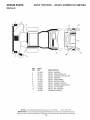
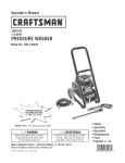
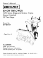
Owner's Manual
CRRFT$14Rli°
SNOW THROWER
1450 Series Briggs and Stratton Engine
Power-Propelled
30" Two-Stage
Model No.
917.881064
• Espafiol, p. 21
CAUTIO
."
Read and follow all
Safety Rules and Instructions
before operating this equipment
Sears, Roebuck and Co., Hoffman Estates, IL 60179 U.S.A.
Visit our Craftsman
website:
www.sears.com/craftsman
iMPORTANT
Safe Operation
Practices
for Walk-Behind
Snow Throwers
This snow thrower is capable of amputating hands and feet and throwing objects.
Failure to observe the following safety instructions could result in serious injury.
&
Look for this symbol to point out ira=
portant safety precautions. It means
CAUTION!!! BECOMEALERT!!!
YOUR
SAFETY IS INVOLVED.
&
WARNING: Always disconnect spark
plug wire and place it where it cannot
contact plug in order to prevent acci=
dental starting when setting up, transporting, adjusting or making repairs.
&
WARNING: Snow throwers
have ex=
posed rotating parts, which can cause
severe injury from contact, or from ma=
terial thrown from the discharge chute.
Keep the area of operation clear of all
persons, small children and pets at all
times including startup.
parts become
CAUTION:
Muffler
extremely
and other
hot during
engine
operation and remain hot after engine
_
WARNING: This snow thrower is for
use on sidewalks, driveways and other
ground level surfaces. Caution should
be exercised while using on sloping sur=
faces. Do not use snow thrower on
surfaces above ground level such as
roofs of residences, garages, porches
or other such structures or buildings.
contact,
as stopped.
stay To
away
avoid
from
severe
theseburns
areas.on
&
WARNING: Engine exhaust, some of
its constituents, and certain vehicle
components contain or emit chemi=
cals known to the State of California
to cause cancer and birth defects or
other reproductive harm.
Training
1.
2.
Read, understand and follow all instructions on
machine and in the manual(s) before operating
unit. Be thoroughly familiar with the controls and
proper use of the equipment. Know how to stop
unit and disengage the controls quickly.
(f) Keep the nozzle in contact with the rim of the fuel
the
this
the
the
tank or container opening at all times, until refueling is complete. Do not use a nozzle lock-open
device.
(g) Replace gasoline cap securely and wipe up spilled
fuel.
Never allow children to operate the equipment. Never
allow adults to operate the equipment without proper
instruction.
3.
Keep the area of operation clear of all persons, particularly small children.
4.
Exercise caution to avoid slipping or falling, especially
when operating the snow thrower in reverse.
(h) If fuel is spilled on clothing, change clothing immediately.
.
Preparation
1.
Thoroughly inspect the area where the equipment is
to be used and remove all doormats, sleds, boards,
wires, and other foreign objects.
2.
Disengage all clutches and shift into neutral before
starting the engine (motor).
3.
Do not operate the equipment without wearing adequate
winter garments. Avoid loose fitting clothing that can
get caught in moving parts. Wear footwear that will
improve footing on slippery surfaces.
4.
Use extension cords and receptacles as specified by
the manufacturer for all units with electric drive motors
or electric starting motors.
5.
7.
Never attempt to make any adjustments while the
engine (motor) is running (except when specifically
recommended by manufacturer).
.
Always wear safety glasses or eye shields during operation or while performing an adjustment or repair to
protect eyes from foreign objects that may be thrown
from the machine.
Operation
1.
Do not put hands or feet near or under rotating parts.
Keep clear of the discharge opening at all times.
2.
Exercise extreme caution when operating on or crossing gravel drives, walks, or roads. Stay alert for hidden
hazards or traffic.
3.
After striking a foreign object, stop the engine (motor),
remove the wire from the spark plug, disconnect the
cord on electric motors, thoroughly inspect the snow
thrower for any damage, and repair the damage before
restarting and operating the snow thrower.
4.
If the unit should start to vibrate abnormally, stop the
engine (motor) and check immediately for the cause.
Vibration is generally a warning of trouble.
5.
Stop the engine (motor) whenever you leave the operating position, before unclogging the collector/impeller
housing or discharge chute, and when making any
repairs, adjustments or inspections.
Handle fuel with care; it is highly flammable
(a) Use an approved fuel container.
(b) Never add fuel to a running engine or hot engine.
(c) Fill fuel tank outdoors with extreme care. Never fill
fuel tank indoors.
(d) Never fill containers inside a vehicle or on a truck
or trailer bed with a plastic liner. Always place
containers on the ground, away from your vehicle,
before filling.
(e) When practical, remove gas-powered equipment
from the truck or trailer and refuel it on the ground.
If this is not possible, then refuel such equipment
on a trailer with a portable container, rather than
from a gasoline dispenser nozzle.
Adjust the collector housing height to clear gravel or
crushed rock surface.
2
6. Whencleaning,
repairingorinspectingthesnowthrower,Clearing a Clogged Discharge Chute
stoptheengineandmakecertainthecollector/impel- Hand contact with the rotating impeller inside the discharge
ler andall movingparts havestopped.Disconnect chute is the most common cause of injury associated with
thesparkplugwireandkeepthewireawayfromthe
snow throwers. Never use your hand to clean out the displug.topreventsomeone
fromaccidentally
startingthe
charge chute. To clear the chute:
engine.
1. SHUT THE ENGINE OFF!
7. Donot runthe engineindoors,exceptwhenstarting
theengineandfortransporting
thesnowthrowerinor
2. Wait 10 seconds to be sure the impeller blades have
outof thebuilding.Opentheoutsidedoors;exhaust
stopped rotating.
fumesaredangerous.
3. Always use a clean-out tool, not your hands.
8. Exercise
extremecautionwhenoperating
onslopes.
Maintenance
and Storage
9. Neveroperatethe
snowthrower
withoutproperguards,
andothersafetyprotective
devicesinplaceandwork1. Check shear bolts and other bolts at frequent intervals
ing.
for proper tightness to be sure the equipment is in safe
working condition.
10.Neverdirectthe dischargetowardpeopleor areas
wherepropertydamagecanoccur.Keepchildrenand
2. Never store the machine with fuel in the fuel tank
othersaway.
inside a building where ignition sources are present
such as hot water heaters, space heaters, or clothes
11. Donotoverloadthe machinecapacitybyattempting
toclearsnowattoofasta rate.
dryers. Allow the engine to cool before storing in any
enclosure.
12.Neveroperatethemachineat hightransportspeeds
3. Always refer to operator's manual for important details
onslipperysurfaces.Lookbehindandusecarewhen
if the snow thrower is to be stored for an extended
operatinginreverse.
period.
13. Disengage
powertothecollector/impeller
whensnow
4. Maintain or replace safety and instruction labels, as
throweris transported
or notin use.
necessary.
14.Useonlyattachments
andaccessories
approvedby
5. Run the machine a few minutes after throwing snow
themanufacturer
ofthesnowthrower(suchaswheel
to prevent freeze-up of the collector/impeller.
weights,counterweights,
or cabs).
15.Neveroperatethesnowthrowerwithoutgoodvisibility
orlight.Alwaysbesureofyourfooting,andkeepafirm
holdonthehandles.Walk;neverrun.
16.Nevertoucha hotengineormuffler.
TA
L
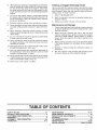
OF CONTENTS
SAFETY RULES ........................................................
2-3
PRODUCT SPECIFICATIONS ...................................... 4
CUSTOMER RESPONSIBILITIES ................................ 4
WARRANTY ..................................................................
4
ASSEMBLY / PRE-OPERATION ............................... 6-8
OPERATION ............................................................
9=14
MAINTENANCE .....................................................
15=16
MAINTENANCE SCHEDULE ..................................... 15
SERVICE AND ADJUSTMENTS ........................... 17-19
STO RAG E .............................................
19
TROUBLESHOOTING ................................................
20
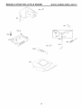
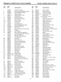
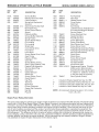
REPAIR PARTS .....................................................
40-65
SEARS SERVICE ................................... BACK COVER
LIMITED 2-YEAR WARRANTY
ON CRAFTSMAN
SNOW THROWER
When used and maintained according to the operator's manual instructions, if this snow thrower fails due to a
defect in material or workmanship within two years from the date of purchase, call 1-800-4-MY-HOME® to arrange
for free repair.
During the first 30 days of purchase, there will be no charge to service the product in your home. For your
convenience, in-home warranty service will still be available after the first 30 days of purchase, but a trip charge
will apply. This charge will be waived if you transport the product to an authorized Craftsman drop-off location. For
the nearest authorized location, call 1-800-4-MY-HOME®.
Warranty coverage does not include:
• Expendable items that become worn during normal use, including but not limited to spark plugs, shear pins, belts.
• Standard maintenance servicing, oil changes, or tune-ups.
• Tire replacement or repair caused by punctures from outside objects, such as nails, thorns, stumps, or glass.
• Repairs necessary because of operator abuse, including but not limited to damage caused by impacting objects
that bend the frame, crankshaft or auger, or over-speeding the engine.
• Repairs necessary because of operator negligence, including but not limited to damage caused by improper
storage, failure to use the proper grade and amount of engine oil, or failure to maintain the equipment according
to the instructions contained in the operator's manual
• Engine (fuel system) cleaning or repairs necessary because of fuel determined to be contaminated or oxidized
(stale). In general, fuel should be used within 30 days of its purchase date.
• Normal deterioration and wear of the exterior finishes, or product label replacement.
This warranty applies for only 90 days if this product is used for commercial or rental purposes.
This warranty applies only while this product is within the United States.
This warranty gives you specific legal rights, and you may also have other rights, which vary, from state to state.
Sears, Roebuck And Co., Hoffman Estates, IL 60179
PRODUCT
CONGRATULATIONS on your purchase of a new snow
thrower. It has been designed, engineered and manufactured to give best possible dependability and performance.
SPECIFICATIONS
Gasoline Capacity 3.0 Quarts
and Type:
Unleaded Regular only
Should you experience any problem you cannot easily remedy, please contact your nearest Sears Parts &
Repair Center. We have competent, well-trained technicians and the proper tools to service or repair this unit.
Please read and retain this manual.
The instructions
will enable you to assemble and maintain your snow
thrower properly. Always observe the "SAFETY RULES".
SERIAL NUMBER:
Oil Type
(API SG-SL):
SAE 5W-30 or 10W-30
Synthetic SAE 5W-30
Oil Capacity:
18 Ounces
Spark Plug:
Gap:
Champion RJ19LM
0.030"
DATE OF PURCHASE:
THE MODELAND SERIAL NUMBERSWILL BE FOUND
ON A DECALATTACHED TO THE REAR OFTHE SNOW
THROWER HOUSING.
CUSTOMER
YOU SHOULD RECORD BOTH SERIAL NUMBER AND
DATE OF PURCHASE AND KEEP IN A SAFE PLACE
FOR FUTURE REFERENCE.
•
Read and observe the safety rules.
•
Follow a regular schedule in maintaining, caring for
and using your snow thrower.
Follow the instructions under "Maintenance" and "Storage" sections of this owner's manual.
•
4
RESPONSIBILITIES
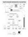
PARTS PACKE
E
ELY I
(1) FUEL STABiLiZER
CARTON
(1) MULTiWRENCH
PACKET
(180684)
FRES_
(1) SAFTEY iGNiTiON
(193071)
(1) POWER CORD
(198583)
(1) AUGER
CONTROL
KEY
ROD
_1111111
(1) TRACTION
(1) DISCHARGE
DRIVE
CONTROL
ROD
CHUTE
r
I
EXTRA SHEAR BOLTS AND NUTS
©
I
I
I
(2) SHOULDER
BOLT 1/4=20 x 1=3/4
(2) LOCKNUTS
1/4=20
(192090)
(73800400)
1
ROTATOR HEAD MOUNTING
I
(3) RETAINER
SPRINGS
I
(189875)
I
(1) WASHER 3/8
(19131316)
(1) LOCKNUT
(73800600)
3/8
I
J
CHUTE DEFLECTOR REMOTE CONTROL
(1) LOCKNUT
5/16-18
(751153)
(1) CARRIAGE
BOLT
5/16=18 x 5/8
(72250505)
(1) LOCKNUT
1/4=20
(191730)
(1) NYLON
WAS H E R
(179246)
(1) SHOULDER
BO LT 1/4=20
(179829)
(1)
(184505)
7
I
I
I
(2) FLAT WASHERS
(2) CARRIAGE
BOLTS
3/8=16 x 2.25
(2) HANDLE
KNOBS
I
I
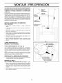
ASSE
BLY / PRE-OPERATION
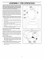
Read these instructions and this manual in its entirety
before you attempt to assemble or operate your new
snow thrower. Reading the entire manual will familiarize you with the unit, which will assist you in assembly,
operation and maintenance of the product.
SPEED
CONTROL
ROD_
PLASTIC TIE
Your new snow thrower has been assembled at the factory
with the exception of those parts left unassembled for shipping purposes. All parts such as nuts, washers, bolts, etc.,
necessary to complete the assembly have been placed in
the parts bag. To ensure safe and proper operation of your
snow thrower, all parts and hardware you assemble must
be tightened securely. Use the correct tools as necessary
to ensure proper tightness.
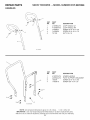
REMOVE
SNOW THROWER
HANDLE
KNOB
FROM CARTON
1.
Remove all accessible loose parts and parts boxes
from carton.
2.
Cut down all four corners of carton and lay panels flat.
3.
Remove the two (2) screws securing the auger housing
to the pallet.
4.
Remove all packing materials except plastic tie holding
speed control rod to lower handle.
5.
Remove the two (2) plastic ties securing upper handle
to pallet.
Remove snow thrower from carton and check carton
thoroughly for additional loose parts.
6.
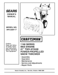
UPPER
HANDLE
LOWER
HANDLE
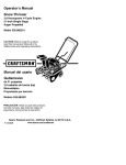
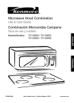
HOW TO SET UP YOUR SNOW THROWER
FIG. 1
TOOL BOX (See Fig. 10)
A toolbox is provided on your snow thrower. The toolbox is
located on top of the belt cover. Store the extra shear bolts,
nuts and multi-wrench provided in parts bag in the toolbox.
SPEED CONTROL
RETAINER
SPRING
NOTE: The multi-wrench may be used for assembly of the
chute rotator head to snow thrower and making adjustments
to the skid plates.
UNFOLD UPPER HANDLE
.
Raise upper handle to the operating position and
tighten handle knobs securely. Additional carriage
bolts, washers and handle knobs are in bag of parts.
Use to secure upper handle to lower handle. Install
in lower holes in handles.
SPEED
CONTROL
BRACKET
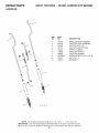
iNSTALL SPEED CONTROL ROD (See Figs. 1 and 2)
1.
Remove plastic tie securing rod to lower handle.
2.
Insert rod into speed control bracket and secure with
retainer spring.
SPEED
CONTROL
LEVER
FIG. 2
6
ROD
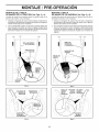
LY /
E-OPERATION
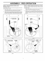
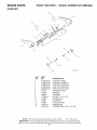
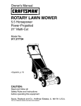
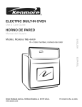
iNSTALL TRACTION DRIVE CONTROL ROD
iNSTALL AUGER CONTROL ROD (See Figs. 5 and 6)
(See Figs. 3 and 4)
The auger control rod has the short loop on the end of the
spring as shown.
The traction drive control rod has the long loop on the end
of the spring as shown.
1.
Slide rubber sleeve up rod and hook end of spring into
pivot bracket with loop opening down as shown.
2.
With top end of rod positioned under left side of control
panel, push rod down and insert top end of rod intohole
in drive control bracket. Secure with retainer spring.
1.
Slide rubber sleeve up rod and hook end of spring into
control arm with loop opening up as shown.
2.
With top end of rod positioned under right side of
control panel, push down on rod and insert end of rod
into hole in auger control bracket. Secure with retainer
spring.
DRIVE
AUGER
CONTROL
ROD
RUBBER
SLEEVE
CONTROL
ARM
BRACKET
FIG. 3
DRIVE
FiG, 5
RETAINER
SPRING
AUGER CONTROL
ROD
RETAINER
SPRING
AUGER
CONTROL
LEVER
CONTROL
BRACKET
CONTROL
BRACKET
FIG. 4
FIG. 6
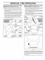
ASSE
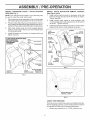
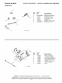
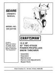
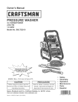
iNSTALL DISCHARGE
HEAD (See Fig. 7)
CHUTE
BLY/PRE-OPERATION
/ CHUTE
iNSTALL
ROTATOR
2.
3.
4.
DEFLECTOR
REMOTE
Place discharge chute assembly on top of chute base
with discharge opening toward front of snow thrower.
Position chute rotator head over chute bracket. If necessary, rotate chute assemblyto align square and pin on underside of chute rotator head with holes in chute bracket.
2.
Install remote cable eyelet to chute deflector with
1/4-20 shoulder bolt, nylon washer and 1/4-20 Iocknut
as shown. Tighten securely.
3.
Install spring hooks between hex nuts on chute rotator
head and into hole in chute deflector as shown.
With chute rotator head and chute bracket aligned,
position chute rotator head on pin and threaded stud
of mounting bracket.
Install 3/8 washer and Iocknut on threaded stud and
tighten securely.
1/4-20
SHOULDER
SPRING
CHUTE
DEFLECTOR
HOOK
BETWEEN
HEX NUTS
ON CHUTE
ROTATO R
HEAD
NYLON
WASHER
_3/8
LOCKNUT
_3/8
WASHER
CONTROL
(See Figs. 8 and 9)
1. Install remote cable bracket to discharge chute with
5/16-18 carriage bolt and 5/16-18 Iocknut as shown.
Tighten securely.
NOTE: The multi-wrench provided in your parts bag may
be used to install the chute rotator head.
1.
CHUTE
1/4-20
LOCKNUT
CABLE
EYELET
_B
_EMOTE
CABLE
RACKET
PiN
5/16-18
LOCKNUT
STUD
FIG. 8
CHUTE
BRACKET
ROTATOR HEAD
CHUTE
MOUNTING
ROTATOR HEAD
BRACKET
FIG. 7
CHUTE DEFLECTOR
CONTROLLEVER
FIG. 9
CHECK TiRE PRESSURE
The tires on your snow thrower were overinflated at the factory for shipping purposes. Correct and equal tire pressure
is important for best snow throwing performance.
•
8
Reduce tire pressure to 14-17 PSI (19-24.5 N-m).
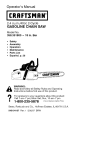
OPERATI
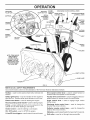
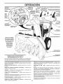
KNOW YOUR SNOW THROWER
READ THIS OWNER'S MANUALAND ALL SAFETY RULES BEFORE OPERATING YOUR SNOWTHROWER.
Compare
the illustrations with your snow thrower to familiarize yourself with the location of various controls and adjustments. Save
this manual for future reference.
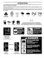
These symbols may appear on your snow thrower or in literature
their meaning.
supplied with the product. Learn and understand
I\1
DANGER
OR WARNING
FUEL
ENGINE
OFF
ENGINE
ON
OIL
FORWARD
REVERSE
IGNITION KEY.
INSERT TO START
AND RUN,
PULL OUT TO STOP.
DISENGAGED
ENGAGED
SNOW
DISCHARGE
TRACTION
DRIVE CONTROL
FAST
SLOW
CHOKE
PRIMER
READ AND FOLLOW ALL SAFETY INFORMATION
AND INSTRUCTIONS
BEFORE USE OF THiS PRODUCT.
KEEP THESE INSTRUCTIONS
FOR FUTURE REFERENCE.
OPERATION
ELECTRIC
START BUTTON
GASOLINE
AUGER
CONTROL
LEVER
STARTER
RECOIL
HANDLE
DISCHARGE
DRIVE SPEED
_ONTROL
CHUTE CONTROL
LEVER
DEFLECTOR REMOTE
CONTROLLEVER
LEVER
CHUTE
DEFLECTOR
DRIVE
CONTROL
LEVER
CONTROL
=H TURN
TRIGGER
SAFETY
iGNiTiON
KEY
LIGHT
CHUTE
ON / OFF
SWITCH
CLEAN=OUT TOOL
KNOB
TOOLBOX
NOTE: iTEMS ABOVE
ARE SHOWN iN
THEIR TYPICAL
LOCATION ON THE
ENGINE. ACTUAL
LOCATION MAY VARY
WITH THE ENGINE
ON YOUR UNIT,
\
O
DRIFT CUTTER
PLATE
AUGERS
FIG. 10
MEETS A.N.S.I. SAFETY REQUIREMENTS
Our snow throwers conform to the standards of the American National Standards Institute.
Toolbox = used to store spare shear bolts, locknuts and
wrench.
Drive speed control lever = used to select forward or
reverse motion and speed of snow thrower.
Safety ignition key - must be inserted for the engine to
start and run. Remove when snow thrower is not in use.
Traction drive control lever = used to engage power-propelled forward or reverse motion of snow thrower.
Electric start button = used for starting the engine.
Auger control
(throw snow).
Recoil (auxiliary) starter handle- used for starting engine.
lever = used to engage auger motion
Primer = pumps additional fuel from the carburetor to the
cylinder for use when starting a cold engine.
Discharge chute control lever = used to change the
direction the snow is thrown.
Choke Control = used for starting a cold engine.
Deflector remote control lever = used to change the
distance the snow is thrown.
ON / OFF switch - used to STOP the engine.
Skid plate = used to adjust height of scraper bar from ground.
LH and RH turn triggers - used to steer the snow thrower.
10
Drift cutter - used to cut through deep snowdrifts.
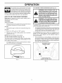
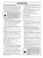
OPERATI
The operation of any snow thrower can result
in foreign objects thrown intothe eyes, which
can result in severe eye damage. Always wear
safety glasses or eye shields while operating
your snow thrower or performing any adjustments or repairs. We recommend standard safety glasses
or a wide vision safety mask worn over spectacles.
TO CONTROL SNOW DISCHARGE
&
WARNING: Snow throwers
have ex=
posed rotating parts, which can cause
severe injury from contact, or from ma=
terial thrown from the discharge chute.
Keep the area of operation clear of all
persons, small children and pets at all
times including startup.
&
WARNING: if the discharge chute or
auger become clogged, shut=off engine
and wait for all moving parts to stop. Use
the clean=out tool, NOT YOUR HANDS,
to unclog the chute and/or auger.
HOW TO USE YOUR SNOW THROWER
Know how to operate all controls before adding fuel or
attempting to start the engine.
STOPPING
TRACTION
DRIVE
Release traction drive control lever to stop the forward
or reverse movement of the snow thrower.
The DIRECTION inwhich snow isto be thrown is controlled
by the discharge chute control lever.
AUGER
•
Release the auger control lever to stop th rowing snow.
ENGINE
1.
Move ON / OFF switch to "OFF" position.
2.
Remove (do not turn) safety ignition key to prevent
unauthorized use.
Tochange the discharge chute position, press downward
on discharge chute control lever and move lever left
or right until chute is in desired position. Be sure lever
springs back and locks into desired position.
The DISTANCE that snow is thrown is controlled by the
position of the chute deflector. Set the deflector low to
throw snow a short distance; set the deflector higher to
throw snow farther.
NOTE: Never use choke to stop engine.
TO USE CHOKE CONTROL (See Fig. 11)
Press downward on chute deflector control lever and
move lever forward to lower the deflector and decrease
the distance. Move lever back to raise the deflector
and increase the distance. Be sure lever springs back
and locks into desired position.
The choke control is located on the engine. Use the choke
control whenever you are starting a cold engine. Do not
use to start a warm engine.
To engage choke, turn knob counterclockwise.
turn knob clockwise to disengage.
(See Fig. 12)
Slowly
DISCHARGE CHUTE
CONTROLLEVER
I\l
CHUTE DEFLECTOR
REMOTE CONTROLLEVER
FIG. 11
FIG. 12
11
OPERATION
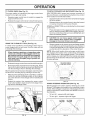
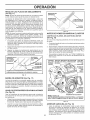
TO THROW SNOW (See Fig. 13)
TO MOVE FORWARD AND BACKWARD (See Fig. 15)
SELF-PROPELLING, forward and reverse movement of
the snow thrower, is controlled by the traction drive control
lever located on the left side handle.
The auger rotation is controlled by the auger control lever
located on the right side handle.
•
•
Squeeze auger control lever to handle to engage the
auger and throw snow.
•
Squeeze traction drive control lever to handle to engage
the drive system.
•
Release traction drive control lever to stop the forward
or reverse movement of the snow thrower.
Release the auger control lever to stop throwing snow.
AUGER
CONTROL
LEVER
SPEED and DIRECTION are controlled by the drive speed
control lever.
Press downward on the speed control lever and move
lever to desired position BEFORE engaging the traction drive control lever. Be sure lever springs back and
locks into desired position.
CAUTION: Do not move speed control lever
when traction drive control lever is engaged.
Damage to the snow thrower can result.
FIG. 13
USING THE CLEAN=OUT TOOL (See Fig. 14)
•
In certain snow conditions, the discharge chute may become clogged with ice and snow. Use the clean-out tool
to dislodge this blockage.
NOTE: When both traction drive and auger control levers
are engaged, the traction drive control lever will lock the
auger control lever in the engaged position. This will allow
you to release your right hand from the handle and adjust
the discharge chute direction without interrupting the snow
throwing orocess.
When cleaning, repairing, or inspecting, make
certain all controls are disengaged and the au=
get/impeller and all moving parts have stopped.
Disconnect the spark plug wire and keep the
wire away from the spark plug to prevent ac=
cidental starting.
e
Release the auger control lever and shut off the engine.
e
Remove the clean-out tool from it's mounting clip. Grasp
the tool firmly by the handle and push and twist the tool
into the discharge chute to dislodge the blockage.
Slower speeds are for heavier snow and faster speeds
are for light snow and transporting the snow thrower. It
is recommended that you use a slower speed until you
are familiar with the operation of the snow thrower.
TRACTION DRIVE
CONTROL LEVER
After the packed snow has been dislodged, return the cleanout tool to it's mounting clip by pushing it into the clip.
•
•
Make sure the discharge chute is pointed in a safe direction (no vehicles, buildings, people, or other objects
are in the direction of discharge) before restarting the
engine.
CONTROL
Restart the engine, then squeeze the auger control
lever to the handle to clear snow from the auger housing and the discharge chute.
DISCHARGE
FIG. 15
POWER STEERING OPERATION (See Fig. 10)
Steering triggers are used to assist in steering your snow
thrower. The triggers are located on the underside of each
handle. When a trigger is squeezed, it disengages the drive
wheel on that side of snow thrower and allows it to turn in
that direction.
CHUTE
CLEAN-OUT
TOOL
•
To turn left - squeeze left side trigger.
•
To turn right - squeeze right side trigger.
LH TURN
TRIGGER
FIG, 14
LEVER
12
RH TURN
TRIGGER
FIG. 16
OPERATI
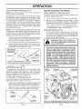
TO ADJUST SKID PLATES (See Fig. 17)
BEFORE
NOTE: The wrench provided in your parts bag may be
used to adjust the skid plates.
CHECK ENGINE OIL LEVEL (See Fig. 19)
NOTE: It is not recommended to operate the snow thrower
over gravel or rocky surfaces. Objects such as gravel, rocks
or other debris, can easily be picked up and thrown by the
impeller, which can cause serious personal injury, property
damage or damage to the snow thrower.
If snow thrower must be operated over gravel surface,
use extra caution and be sure skid plates are adjusted
to lowest (highest scraper clearance) position.
1.
Shut off engine and wait for all moving parts to stop.
2.
Adjustskid plates by loosening the hex nuts, then moving skid plate to desired position. Be sure both plates
are adjusted evenly. Tighten securely.
/
i
-"/
.--
.
==
SCRAPER
__=.._
NUTS=
=
Check engine oil with snow thrower on level ground.
2.
Remove oil fill cap/dipstick and wipe clean, reinsert
the dipstick and screw tight, wait for a few seconds,
remove and read oil level. If necessary, add oil until
"FULl" mark on dipstick is reached. Do not overfill.
•
To change engine oil, see "TO CHANGE ENGINE OIL'
in the Maintenance section of this manual.
d
_JL
fuel. Do not store, spill or use gasoline
WARNING:
off any spilled oil or
near
an openWipe
flame.
CAUTION: Alcohol blended fuels (called gasohol or using ethanol or methanol) can attract
moisture which leads to separation and for=
mation of acids during storage. Acidic gas can
damage the fuel system of an engine while in
storage. To avoid engine problems, the fuel
system should be emptied before storage of
30 days or longer. Empty the gas tank, start
the engine and let it run until the fuel lines and
carburetor are empty. Use fresh fuel next sea=
son. See Storage instructions
for additional
information. Never use engine or carburetor
cleaner products in the fuel tank or permanent
damage may occur.
AUGER
HOUSING
I
1.
ADD GASOLINE (See Fig. 19)
Fill fuel tank to bottom of tank filler neck. Do not overfill. Use fresh, clean, regular unleaded gasoline with
a minimum of 87 octane. Do not mix oil with gasoline.
Purchase fuel in quantities that can be used within 30
days to assure fuel freshness.
HIGH
(LOW GROUND
II
THE ENGINE
The engine on your snow thrower has been shipped, from
the factory, already filled with oil.
Skid plates are located on each side of the auger housing
and adjust the clearance between the scraper bar and the
ground surface. Adjust skid plates evenly to proper height
for current surface conditions. For removal of snow in
normal conditions, such as a paved driveway or sidewalk,
place skid plates in the highest position (lowest scraper
clearance) to give a 5 mm clearance between the scraper
bar and the ground. Use a middle position if the surface
to be cleared is uneven.
•
STARTING
BAR
PLATE
/
LOW POSITION (HIGH GROUND CLEARANCE)
FIG. 17
SCRAPER BAR (See Fig. 17)
The scraper bar is not adjustable, but is reversible. After
considerable use it may become worn. When it has worn
almost to the edge of the housing, it can be reversed,
providing additional service before requiring replacement.
Replace a damaged or worn scraper bar.
CHOKE
CONTROL
ENGINE OIL
FILL CAP / DIPSTICK
GASOLINE
FILLER CAP
STARTER
BUTTON
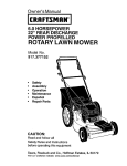
TO USE DRIFT CUTTERS (See Fig. 18)
Use the drift cutters to cut through deep snowdrifts that are
higher than the front of the snow thrower.
•
Loosen upper adjustment nut enough to allow drift
cutter to be raised to highest position and tighten nut
securely. Repeat for opposite side of snow thrower.
When not using drift cutters, loosen adjustment nut,
lower to storage position and tighten nut securely.
AUGER
HOUSING
PRIMER
DRIFT
CUTTER
SAFETY
IGNITION
KEY
ADJUSTMENT NUT
FIG. 18
RECOIL
STARTER
HANDLE
ON / OFF
SWITCH
NOTE: ALL ITEMS ARE SHOWN IN THEIR TYPICAL LOCATION.
ACTUAL LOCATION MAY VARY WiTH ENGINE ON YOUR UNIT.
13
FIG. 19
OPERATION
TO START ENGINE
5.
Your snow thrower engine is equipped with both a 120 Volt
A.C. electric starter and a recoil starter. The electric starter
is equipped with a three-wire power cord and plug and is
designed to operate on 120 Volt A.C. household current.
Pull recoil starter handle quickly. Do not allow starter
rope to snap back.
6.
When the engine starts, release the recoil starter handle
and slowly move the choke control to the "OFF" position.
•
Be sure your house is a 120 Volt A.C. three-wire
grounded system.
If you are uncertain, consult a
licensed electrician.
WARNING:
Do not
A.C.
three=wire
starter
if your
rious personal
snow thrower
use the
Allow the engine to warm up for afew minutes. Engine will
not develop full power until it has reached normal operating temperature.
WARM START- RECOIL STARTER
electric
Follow the steps above, keeping the choke in the "OFF"
position. DO NOT push the primer.
grounded
system.
Se=
house
is not
a 120 Volt
injury or damage to your
could result.
BEFORE STOPPING
COLD START - ELECTRIC STARTER
Run the engine for a few minutes to help dry off any moisture on the engine.
1.
Insert safety ignition key (packed separately in parts
bag) into ignition slot until it clicks. DO NOT turn the key.
Keep the extra safety ignition key in a safe place.
IF RECOIL STARTER HAS FROZEN
2.
Place ON / OFF switch in "ON" position.
1.
3.
Rotate choke control to "FULl" position.
Grasp the recoil starter handle and slowly pull as much
rope out of the starter as possible.
4.
Connect the power cord to the engine.
2.
5.
Plug the other end of the power cord into a three-hole
grounded 120 Volt A.C. receptacle.
Release the recoil starter handle and let it snap back
against the starter.
If the recoil starter has frozen and will not turn the engine,
proceed as follows:
If the engine still fails to start, repeat the above steps or
use the electric starter.
NOTE: Do not use primer when starting engine with the
electric starter.
6.
SNOW THROWING
Push starter button until engine starts.
•
IMPORTANT: Do not crank engine more than five continuous seconds between each time you try to start. Wait
5 to 10 seconds between each attempt.
7.
When the engine starts, release the starter button and
slowly move the choke control to the "OFF" position.
8.
Disconnect the power cord from the receptacle first,
then from the engine.
•
Allow the engine to warm up for a few minutes. Engine will
not develop full power until it has reached normal operating temperature.
WARM START - ELECTRIC STARTER
Follow the steps above, keeping the choke control in the
"OFF" position.
COLD START - RECOIL STARTER
1.
Insert safety ignition key (packed separately in parts
bag) into ignition slot until it clicks. DO NOT turn the key.
Keep the extra safety ignition key in a safe place.
2.
Place ON / OFF switch in "ON" position.
3.
Rotate choke control to "FULl" position.
4.
Push the primer four (4) times if the temperature is
below 15°F, or two (2) times if temperature is between
15 ° and 50°R If temperature is above 50°F, priming is
not necessary.
Go slower in deep, freezing or heavy wet snow. Use
the drive speed control, NOT the ON / OFF switch, to
adjust speed.
It is easier and more efficient to remove snow immediately after it falls.
•
The best time to remove snow is the early morning. At
this time the snow is usually dry and has not been exposed to the direct sun and warming temperatures.
•
Slightly overlap each successive
snow will be removed.
e
Throw snow downwind whenever possible.
e
Adjust the skid plates to proper height for current snow
conditions. See "TO ADJUST SKID PLATES" in this
section of this manual.
•
For extremely heavy snow, reduce the width of snow
removal by overlapping previous path and moving
slowly.
•
Keep engine clean and clear of snow during use. This
will help air flow and extend engine life.
•
After snow-throwing iscompleted, allow engine to run for
a few minutes to melt snow and ice off the engine.
•
Clean the entire snow thrower thoroughly after each
use and wipe dry so it is ready for next use.
&
NOTE: Over priming may cause flooding, preventing the
engine from starting. If you do flood the engine, wait a few
minutes before attempting to start and DO NOT push the
primer.
14
TiPS
path to ensure all
WARNING:
Do not operate snow
thrower if weather conditions impair visibility. Throwing snow during a heavy,
windy snowstorm can blind you and be
hazardous to the safe operation of the
snow thrower.
E A
CE
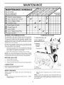
MAINTENANCE
FILL IN DATES
AS YOU COMPLETE
REGULAR SERVICE
Check for Loose Fasteners
R
O
W
v'
Clean / Inspect Snow Thrower
Check/Replace
RE Lubrication
i=
N
v'
V=Belts
Chart
Check Engine Oil Level
Change
v'
Engine Oil
Inspect Muffler
N
E
Check / Replace
v'
Spark Plug
v'
Empty Fuel Tank
GENERAL
RECOMMENDATIONS
LUBRiCATiON
The warranty on this snow thrower does not cover items
that have been subjected to operator abuse or negligence.
To receive full value from the warranty, operator must
maintain snow thrower as instructed in this manual. Some
adjustments will need to be made periodically to properly
maintain your snow thrower.
(_ SAE 5W=30 Motor Oil
(_) See "ENGINE" in
Maintenance section
(_ General
Purpose
Grease
At least once a season, check to see if you should make
any of the adjustments described in the Service and Adjustments section of this manual.
•
•
CHART
At least once a year, you should replace the spark plug
and check belts for wear. A new spark plug will help
your engine run better and last longer.
Follow the maintenance schedule in this manual.
@ Engine oil
NOTE: Use only Original Equipment Manufacturer (OEM)
parts to service this unit. Failure to do so can cause the unit
to malfunction and pose a risk of injury to the operator.
BEFORE
EACH USE
1.
2.
Check engine oil level.
Check for loose fasteners.
3.
Check controls to be sure they are functioning properly.
(_ Pivot
LUBRICATION
points
Keep your snow thrower well lubricated
(See "LUBRICATION CHART").
® Auger
grease fittings
SNOW THROWER
Always observe the safety rules when performing any
maintenance.
•
TIRES
NOTE: To seal tire punctures and prevent flat tires due
to slow leaks, tire sealant may be purchased from your
local parts dealer. Tire sealant also prevents tire dry rot
and corrosion.
•
Maintain proper air pressure in both tires (14-17 RS.I.
/ 19-24.5 N-m).
15
Keep tires free of gasoline and oil, which can harm
rubber.
INTEN
CE
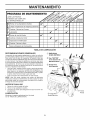
V-BELTS
TO CHANGE ENGINE OIL
Check V-belts for deterioration and wear after every 50
hours of operation and replace if necessary. The belts
are not adjustable. Replace belts if they begin to slip from
wear. (See "TO REMOVE BELT COVER" in the Service
and Adjustments section of this manual).
Determine temperature range anticipated before next oil
change. All oil must meet API service classification SG-SL.
•
Be sure snow thrower is on level surface.
•
•
The V-belts on your snow thrower are of special construction
and should be replaced by original equipment manufacturer
(OEM) belts available from your nearest dealer. Using other
than OEM belts can cause personal injury or damage to
the snow thrower.
Oil will drain more freely when warm.
Catch oil in a suitable container.
NOTE: The left side wheel may be removed from snow
thrower for easier access to the oil drain plug and placement of a suitable container. The unit tilted, resting on the
frame with the left wheel removed, will help drain any oil
trapped inside the engine. (See "TO REMOVE WHEELS"
in the Service and Adjustments section of this manual).
AUGER GEAR CASE
The gear case was filled with lubricant to the proper
level at the factory. The only time the lubricant needs
attention is if service has been performed on the gear
case.
1.
Remove safety ignition key and disconnect spark plug
wire from spark plug. Place wire where it cannot come
in contact with plug.
2.
Clean area around drain plug.
TRACTION DRIVE SYSTEM
3.
Remove drain plug and drain oil in a suitable container.
DO NOT lubricate the drive components inside the snow
thrower. The sprockets, hex shafts, drive disc and friction
wheel require no lubrication. The bearings and bushings
are lifetime lubricated and require no maintenance.
4.
Install drain plug and tighten securely.
5.
Wipe off any spilled oil from snow thrower and engine.
6.
Install left wheel (if removed for draining oil). Besureto
install klick pin into proper hole in wheel axle (See "TO
REMOVE WHEELS" in the Service and Adjustments
section of this manual).
7.
Remove oil fill cap/dipstick. Be careful not to allow dirt
to enter the engine.
8.
Refill engine with oil through oil dipstick tube. Pour
slowly. Do not overfill. For approximate capacity see
"PRODUCT SPECIFICATIONS" section of this manual.
LUBRICATION
9.
Use only high quality detergent oil rated with API service
classification SG-SL. Select the oil's SAE viscosity grade
according to your expected operating temperature.
Use gauge on oil fill cap/dipstick for checking level.
Be sure dipstick cap is tightened securely for accurate
reading. Keep oil at "FULE' line on dipstick.
10. Wipe off any spilled oil.
•
If lubricant is required, use only Ronex ED #1 grease.
CAUTION: Any lubricating of the above components can cause contamination of the friction
wheel and damage to the drive system of your
snow thrower.
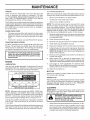
ENGINE
MUFFLER
SAE ViSCOSiTY
GRADES
Inspect and replace corroded muffler as it could create a
fire hazard and/or damage.
SPARK PLUG
!
i °F
-20
i°c -30
0
-2o
Replace spark plug at the beginning of each season or after
every 100 hours of operation, whichever occurs first. Spark
plug type and gap setting are shown in the "PRODUCT
SPECIFICATIONS" section of this manual.
I
30
40
32
40
6
lo
TEMPERATURE RANGE ANTiCiPATED
BEFORE NEXT OiL CHANGE
CLEANING
IMPORTANT." For best performance, keep snow thrower
housing free of any dirt or trash. Clean the outside of your
snow thrower after each use.
NOTE: Although multi-viscosity oils (5W30, 10W30 etc.)
improve starting in cold weather, these multi-viscosity oils
will result in increased oil consumption when used above
32°F/0°C. Check your engine oil level more frequently to
avoid possible engine damage from running low on oil.
&
Change the oil after every 25 hours of operation or at least
once a year if the snow thrower is not used for 25 hours
in one year.
Check the crankcase oil level before starting the engine and
after each five (5) hours of continuous use. Tighten oil fill
cap / dipstick securely each time you check the oil level.
16
WARNING: Remove safety ignition key
and disconnect spark plug wire from
spark plug. Place wire where it cannot
come in contact with plug.
e
Keep finished surfaces/wheels free of gasoline, oil, etc.
e
We do not recommend using a garden hose to clean
your snow thrower unless the electrical system, muffler
and carburetor are covered to keep water out. Water
in engine can result in shortened engine life.
SE
iCE
ADJ
WARNING: To avoid serious injury, before
performing any service or adjustments:
1. Be sure the on/off switch is in the
OFF position.
ENTS
1.
Disengage all controls and move throttle control to
STOP position. Wait for all moving parts to stop.
2.
Remove safety ignitionkey and disconnect spark plug
wire from spark plug. Place wire where it cannot come
in contact with plug.
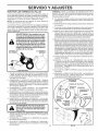
3.
Align holes in impeller hub with holes in impeller shaft
and install two (2) new 1/4-20 x 1-5/8" capscrew/shear
bolts. Install 1/4-20 Iocknuts and tighten securely.
4.
Connect spark plug wire to spark plug. Replace safety
ignition key.
2. Remove
3.
Make suresafety
the augers
ignition
andkey.
all moving
parts have completely stopped.
4. Disconnect spark plug wire from
spark plug and place wire where it
cannot come in contact with plug.
SNOW THROWER
TO ADJUST SNOW THROWER HEIGHT
1/4-20
LOCKNUT
See "TO ADJUST SKID PLATES" and "SCRAPER BAR"
in the Operation section of this manual.
1-5/8
CAPSCREW / _
1/4-20 x 2
SHOULDER /
SHEAR BOLT _-__-'-"---"
IMPELLER HUB
_/SPACER
CHUTE DEFLECTOR
IMPELLER
The chute deflector, attached to the top of the discharge
chute, is provided to direct discharging snow away from
the operator. If the deflector becomes damaged, it should
be replaced.
L_
SHEAR BOLT
_,
never operate your snow thrower with
the deflector removed or damaged.
•
Tochange direction and!or distance snow isdischarged,
see "TO CONTROL SNOW DISCHARGE" in the Operation section of this manual.
AUGER
HUB
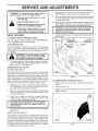
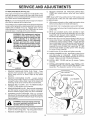
SHEAR BOLTS (See Fig. 20)
AUGER SHEAR BOLTS
1/4-20
Both right and left-hand augers are secured to the auger
shaft with a shoulder/shear bolt and hex nut. Should a foreign object or ice become lodged in the augers, the shear
bolts are designed to break, preventing damage to any
other components. If one or both augers do not turn when
auger control lever is engaged, check to see if one or both
of the bolts have sheared. To replace the shear bolts:
1.
Remove safety ignitionkey and disconnect spark plug
wire from spark plug. Place wire where it cannot come
in contact with plug.
3.
Align hole in auger hub with hole in auger shaft and
install a new 1/4-20 x 2" shoulder/shear bolt. Install
1/4-20 lock nut and tighten securely.
AUGER
SHAFT
FIG. 20
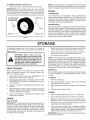
TO REMOVE BELT COVER (See Fig. 21)
Disengage all controls and move throttle control to
STOP position or move ON/OFF switch to OFF position. Wait for all moving parts to stop.
2.
AUGER
HUB
1.
Remove the two (2) screws securing belt cover to
frame.
2.
Remove belt cover.
•
Replace belt cover by installing cover and screws and
tighten securely.
/S
_',_)
_, ....
BELT
COVER
,
equipment shear bolts as supplied with your
snow thrower.
4.
Connect spark plug wire to spark plug. Replace safety
ignition key.
IMPELLER SHEAR BOLTS
The impeller is secured to the impeller shaft with two (2)
capscrew/shear bolts and hex nuts. Should a foreign object
or ice become lodged in the impeller, the capscrews are
designed to break, preventing damage to any other components. If impeller does not turn when auger control lever
is engaged, check to see if the capscrews have sheared.
To replace the capscrew/shear bolts:
-
_%
FRAME
SCREWS
FIG. 21
17
SERVICE A
ADJ
8.
TO REPLACE BELTS (See Fig. 22)
The auger and traction drive belts are not adjustable. If the
belts are damaged or begin to slip from wear, they should
be replaced. It is recommended that the belt(s) be replaced
by a Sears service centre/department.
HINT: Insert a 3/8" drive ratchet (in the "ON" position) into
the square hole in idler arm and rotate ratchet clockwise
to relieve tension.
NOTE: It is recommended that both the auger and traction
drive belt be replaced at the same time.
9.
The V-belts on your snow thrower are of special construction
and should be replaced by original equipment manufacturer
(OEM) belts available from your nearest Sears service
centre/department. Using other than OEM belts can cause
)ersonal injury or damage to the snow thrower.
&
With tension relieved on idler, install new traction drive
belt around pulleys and inside belt keepers.
10. Install clutch rod in swing plate; secure with hairpin.
11. Place auger belt around and inside the groove of auger
pulley only.
12. While your assistant slowly raises handles to rejoin
the auger housing and frame assembly, pull up on the
auger belt and squeeze sides together above pulley
so belt is fully seated in groove of pulley.
WARNING: Belt replacement requires
separation of the snow thrower. While
separating the auger housing from the
frame assembly, it is important that
an assistant stand in the operating
position and hold the snow thrower
handles. Serious personal injury and/or
damage to the unit could occur if the
snowthrower should fall during the belt
changing process.
FRAME
ASSEMBLY
RELIEVE TENSION ON TRACTION DRIVE BELT
IDLER and remove traction drive belt from around
pulleys.
13. Move idler arm so it does not hit impeller pulley as you
bring snow thrower completely together and check
carefully for proper routing of belts. If auger belt has
become dislodged from the pulley (by catching the idler
arm bracket while bringing snow thrower together),
separate the snow thrower and repeat step 12. Belt
must be fully seated in pulley groove when bringing
the snow thrower together.
AUGER
HOUSING
14. Install the two (2) hex bolts and tighten securely.
15. INSTALL ENGINE PULLEY- Place belt in pulley groove
and slide pulley on crankshaft.
Install flat washer,
Iockwasher and bolt and tighten securely (41-47 N-m
torque). Make sure belt is inside belt keeper.
16. INSTALL
securely.
17. INSTALL
CHARGE
Assembly
HANDLES
.
.
REMOVE GASOLINE FROM FUEL TANK - Drain
gasoline from fuel tank into a suitable container, outdoors, away from fire or flame. Wipe up any spilled
gasoline.
REMOVE DISCHARGE CHUTE - Loosen Iocknut
securing chute rotator head to mounting bracket only
enough to allow chute rotator head to be raised and
discharge chute to be removed from snow thrower.
REMOVE BELT COVER - See "TO REMOVE BELT
COVER" in this section of this manual.
4.
REMOVE ENGINE PULLEY- Remove bolt, Iockwasher
and flat washer securing pulley to engine crankshaft.
Remove outside (auger) pulley only from crankshaft.
5.
SEPARATE SNOW THROWER - With your assistant
standing in the operating position holding the handles,
remove the two (2) bolts holding the auger housing and
frame together.
BELT COVER and two (2) screws. Tighten
DISCHARGE CHUTE - See "INSTALL DISCHUTE / CHUTE ROTATER HEAD" in the
/ Pre-Operation section of this manual.
BELT KEEPER
TRACTION
DRIVE BELT
ENGINE
PULLEY
FLAT WASHER
LOCKWASHER
BOLT
AUGER
BELT
IDLER ARM
SQUARE
HOLE
CLUTCHING
BRACKET
IDLER ARM
FRAME
/
AUGER
AUGER
HOUSING
PULLEY
BOLTS
have
your assistant
carefully
lower the
WARNING:
As the last
bolt is removed,
handles down to the ground.
6.
REMOVE HAIRPIN FROM CLUTCH ROD and remove
clutch rod from swing plate. Tip swing plate forward.
7.
REMOVE AUGER BELT from around pulley.
18
FIG.22
TOREMOVE
WHEELS(SeeFig.23)
Removetheklikpinandremovewheelfromaxle.
IMPORTANT:
Wheninstalling wheel, be sure to use the
NOTE: To seal punctures or prevent flat tires due to slow
leaks, tire sealant may be purchased from your local parts
dealer. Tire sealant also prevents tire dry rot and corrosion.
axle hole closest to the end of the shaft - do not use the
hole in the wheel hub (if equipped). Inner hole in axle and
hole in wheel hub are not used for your model snow thrower.
ENGINE
KLIK PiN (iNSTALL
iN OUTER HOLE
OF AXLE ONLY)
OUTER HOLE
CARBURETOR
Your carburetor is not adjustable. Engine performance
should not be affected at altitudes up to 7,000 feet (2,134
meters). If your engine does not operate properly due to
suspected carburetor problems, take your snow thrower
to a Sears service centre/department.
ENGINE SPEED
d
AXLE
WHEEL
WHEELHUB
FIG. 23
Never tamper with the engine governor, which is factory set
for proper engine speed. Overspeeding the engine above
the factory high speed setting can be dangerous and will
void the warranty. If you think the engine-governed high
speed needs adjusting, contact a Sears Parts & Repair
Center, which has the proper equipment and experience
to make any necessary adjustments.
STORAGE
Immediately prepare your snow thrower for storage at
the end of the season or if the unit will not be used for 30
days or more.
&
WARNING:
Never store the snow
thrower with gasoline in the tank inside
a building where fumes may reach an
open flame, spark or pilot light as on a
furnace, water heater, clothes dryer or
gas appliance. AIIowthe engine to cool
before storing in any enclosure.
SNOW THROWER
When snow thrower is to be stored for a period of time,
clean it thoroughly, remove all dirt, grease, leaves, etc.
Store in a clean, dry area.
1.
2.
.
Clean entire snow thrower (See "CLEANING"
Maintenance section of this manual).
in the
Inspect and replace belts, if necessary (See "TO REPLACE BELTS" in the Service and Adjustments section
of this manual).
Lubricate as shown in the Maintenance section of this
manual.
4.
Be sure that all nuts, bolts, screws, and pins are securely
fastened. Inspect moving parts for damage, breakage
and wear. Replace if necessary.
5.
Touch up all rusted or chipped paint surfaces; sand
lightly before painting.
ENGINE
•
Empty the fuel tank by starting the engine and letting
it run until the fuel lines and carburetor are empty.
•
Never use engine or carburetor cleaner products in
the fuel tank or permanent damage may occur.
Use fresh fuel next season.
•
NOTE: Fuel stabilizer is an acceptable alternative in minimizing the formation of fuel gum deposits during storage.
Add stabilizer to gasoline in fuel tank or storage container.
Always follow the mix ratio found on stabilizer container.
Run engine at least 10 minutes after adding stabilizer to
allow the stabilizer to reach the carburetor. Do not empty
the gas tank and carburetor if using fuel stabilizer.
ENGINE OiL
Drain oil (with engine warm) and replace with clean engine
oil. (See "ENGINE" in the Maintenance section of this
manual).
CYLINDER
.
Pour approximately one ounce (30 ml) of oil through
spark plug hole into cylinder.
.
Pull recoil starter handle slowly a few times to distribute
oil.
4.
Replace with new spark plug.
OTHER
•
Remove safety ignition key; store it in a safe place.
•
Do not store gasoline from one season to another.
•
Replace your gasoline can if your can starts to rust.
Rust and/or dirt in your gasoline will cause problems.
•
If possible, store your snow thrower indoors and cover
it to protect it from dust and dirt.
•
Cover your snow thrower with a suitable protective
cover that does not retain moisture. Do not use plastic.
Plastic cannot breathe, which allows condensation to
form and will cause your snow thrower to rust.
FUEL SYSTEM
IMPORTANT: It is important to prevent gum deposits from
forming in essential fuel system parts such as carburetor,
fuel hose, or tank during storage. Alcohol blended fuels
(called gasohol or using ethanol or methanol) can attract
moisture which leads to separation and formation of acids
during storage. Acidic gas can damage the fuel system of
an engine while in storage.
Remove spark plug.
2.
IMPORTANT: Never cover snow thrower while engine/ex19 haust area is still warm.
TROUBLESHOOTI
G
See appropriate section in manual unless directed to a Sears service centre/department.
PROBLEM
CAUSE
CORRECTION
Does not start
1.
2.
3.
4.
5.
6.
7.
8.
iLoss of power
Engine idles or
runs roughly
Fuel shut-off valve (if so
equipped) in OFF position.
Safety ignition key
is not inserted.
Out of fuel.
Throttle in STOP position
(or ON/OFF switch is OFF).
Choke in OFF position.
Primer not depressed.
Engine is flooded.
Spark plug wire is
disconnected.
1.
Turn fuel shut-off valve to OPEN position.
2.
Insert safety ignition key.
3.
4.
Fill fuel tank with fresh, clean gasoline.
Move throttle to FAST position
(or ON/OFF switch to ON position).
Move to FULL position.
Prime as instructed in the Operation section of this manual.
Wait a few minutes before restarting, DO NOT prime.
Connect wire to spark plug.
5.
6.
7.
8.
9. Bad spark plug.
10. Stale fuel.
11. Water in fuel.
9. Replace spark plug.
10. Empty fuel tank & carburetor, refill with fresh, clean gasoline.
11. Empty fuel tank & carburetor, refill with fresh, clean gasoline.
1.
2.
3.
Spark plug wire loose.
Throwing too much snow.
Fuel tank cap is covered
with ice or snow.
1.
2.
3.
Reconnect spark plug wire.
Reduce speed and width of swath.
Remove ice and snow on and around fuel tank cap.
4.
Dirty or clogged muffler.
4.
Clean or replace muffler.
1.
2.
3.
4.
5.
Choke is in FULL position.
Blockage in fuel line.
Stale fuel.
Water in fuel.
Carburetor is in need of
1.
2.
Move choke to OFF position.
Clean fuel line.
3.
4.
5.
Empty fuel tank & carburetor, refill with fresh, clean gasoline.
Empty fuel tank & carburetor, refill with fresh, clean gasoline.
Contact a Sears service centre/department.
Loose parts or damaged
augers or impeller.
1.
Tighten all fasteners. Replace damaged parts. If vibration
remains, contact a Sears service centre/department.
Frozen recoil starter.
1.
See "IF RECOIL STARTER HAS FROZEN"
adjustment or overhaul.
Excessive
vibration
Recoil starter
.
1.
iis hard to pull
in the Operation section of this manual.
Loss of traction
1.
Drive belt is worn.
drive / slowing
iof drive speed
2.
3.
Drive belt is off of pulley.
Friction drive wheel is worn.
Loss of snow
1.
2.
3.
4.
Auger belt is off of pulley.
Auger belt is worn.
Clogged discharge chute.
Augers / impeller jammed.
discharge or
slowing of
snow discharge
1.
2.
3.
Check / replace drive belt.
Check / reinstall drive belt.
Contact a Sears service centre/department.
1.
2.
3.
Check / reinstall auger belt.
Check / replace auger belt.
Clean snow chute.
4.
Remove debris or foreign object from augers / impeller.
20
IMPORTANTE
Procedimientos
de Funcionamiento
Seguro
Para Maquinas
Quitanieves
Esta m&quina puede amputar manos y pies y lanzar objetos.
El no observar las siguientes instrucciones de seguridad puede dar lugar a heridas graves.
Formacibn
Busque
este simbolo
que se_ala las precaueiones
de seguridad de ,importancia.
Quiere decir
iATENCION!
iESTE ALERTO!
SU
SEGURIDAD ESTA COMPROMETIDA.
&
ADVERTENCIA: Siempre desconecte el
alambre de la bujia y p6ngalo donde no
pueda entrar en eontacto con la bujia,
para evitar el arranque pot aceidente,
durante la preparacibn, el transporte, el
ajuste o cuando se hacen reparaciones.
1.
Antes de hacerfuncionar esta unidad hay que leer, comprender y seguir todas las instrucciones en al m&quina
yen el manual(es). Familiarizarse completamente con
los mandos y el uso correcto de la m&quina. Hay que
saber como parar la unidad y desconectar los mandos
r&pidamente.
2.
No permitir nunca que menores de edad utilicen la
maquina. No permitir nunca que adultos sin adecuada
instrucci6n previa utilicen la maquina.
3.
Mantener el &rea de operaci6n libre de toda persona,
especialmente nitros peque_os y animales domestiCOS.
4.
&
ADVERTENCIA: Esta m_quina quitanieves se puede utilizar en aceras,
vias de acceso y otras _reas a nivel
del suelo. Hay que tener precauei6n
us_ndola sobre pendientes. No usar la
m_quina quitanieves en _reas sobre el
nivel del suelo, como techos de easas,
garajes, p6rtieos u otras estructuras o
edificios similares.
ADVERTENCIA: Las m_quinas quita=
nieves tienen partes giratorias expuestas, que pueden causar heridas graves
pot contaeto, o pot material lanzado
desde el eonducto de eyecci6n. Man=
tenet siempre el _rea de operaci6n libre de toda persona, nihos pequehos y
animales dom6stieos, incluso durante
la puesta en marcha.
&
PRECAUCION: El sileneiador y otras
piezas del motor Ilegan a sre e×tremadamente calientes durante la operaci6n
y siguen siendo calientes despu_s de
que el motor haya parado. Para evitar
quemaduras severas, permanezca lejos
de estas _reas.
ADVERTENCIA: El tubo de escape del
motor, algunos de sus constituyentesy
algunoseomponentes delvehiculo con=
tienen o desprenden productos quimicos eonocidos en el Estado de California como causa de c_neer y defeetos al
naeimiento u otrosda_os reproductivos.
Atenci6n a evitar de resbalarse o caerse especialmente
cuando se va marcha atr&s.
Preparaci6n
1.
Inspeccionar a fondo el &rea donde se va a utilizar la
maquina y quitar todos los felpudos, trineos, planchas,
hilos y otros objeto ajenos.
2.
Desconectar todos los embragues en la posici6n neutra
antes de poner en marcha el motor.
3.
No accionar la m&quina sin Ilevar vestidos invernales
adecuados para el exterior. Evitar vestidos sueltos y
colgantes que puedan quedarse atrapados en las partes
giratorias. Calzar zapatos que mejoren la estabilidad
en &reas resbaladizas.
4.
Manejar el carburante con precauci6n; es altamente
inflamable.
(a) Usar un contenedor aprobado para carburante.
(b) No a_adir nunca carburante a un motor en marcha o caliente.
(c) Llenar el dep6sito de carburante al aire libre con
extrema precauci6n. No Ilenar nunca el dep6sito
de carburante al interior de un edificio.
(d) No Ilenar nunca contenedores dentro un vehfculo
o en un cami6n o remolque revestido con forro de
pl&stico. Posicionar siempre los contenedores en
el suelo, lejos de su vehfculo antes de Ilenarlos.
(e) Cuando sea pr&ctico, quitar los aparatos alimentados por gas del cami6n o del remolque y abastecer en el suelo. Si esto no fuera posible, entonces hay que abastecer tales aparatos sobre un
remolque mediante contenedores port&tiles, m&s
bien que con un inyector de distribuci6n de gasolina.
(t) Mantener siempre la boquilla en contacto con el
borde de la apertura del dep6sito de carburante,
hasta que el reaprovisionamiento este completo.
No usar un dispositivo de cierre de la boquilla.
TABLA DE MATERIAS
REGLAS DE SECURIDAD .................................... 21=22
ESPECIFICACIONES
DEL PRODUCTO ................... 23
GARANTIA ........................... ;...................................... 23
MONTAJE / PRE-OPERACION ............................. 25=27
OPERACION ..........................................................
28-34
MANTENIMIENTO ................................................. 34°35
PROGAMA DE MANTENIMIENTO ............................ 34
SERVICIO Y AJUSTES ......................................... 36-38
ALMACENAMIENTO ..................................................
38
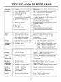
IDENTIFICACION DE PROBLEMAS ......................... 39
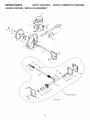
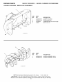
PARTES DE REPUESTO ...................................... 40-65
21 SERVlClO SEARS ...................................... CONTRAPA
5.
6.
7.
8.
(g) Reponereltap6ndecarburante
firmemente
y secarelcarburante
derramado.
(h) Siel carburante
sederramasobrevestidos,cambiarlosinmediatamente.
Paratodaslasunidades
conmotores
demandoel6ctrico
odeencendido
el@ctrico,
usarcablesdeprolongamiento
y receptficulos
especificados
porelfabricante.
Regularlaalturadelamfiquinaquitanieves
paraevitar
fireasdegravillao de pedrisco.
Nointentar
nuncahacerregulaciones
mientras
elmotor
est6en marcha(exceptocuandoestfirecomendado
especfficamente
porelfabricante).
Llevarsiempregafasdeprotecci6n
o mfiscaraspara
losojosdurantelautilizaci6n
delamfiquinao mientras
sehagaunaregulaci6n
ounareparaci6n
paraproteger
losojosdeobjetosextra_osquepuedenserlanzados
porlamaqulnaquitanieves.
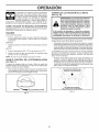
Funcionamiento
1.
No meter las manos o los pies cerca o debajo de partes
giratorias. No acercarse nunca al firea de apertura de
eyecci6n.
2.
Tener extrema cautela mientras la mfiquina funcione en
avenidas, caminos, carreteras de gravilla o los cruce.
Estar alerta por peligros escondidos o trfifico.
3.
Si la unidad empezara a vibrar de manera anormal,
parar el motor y controlar inmediatamente para detectar
la causa. Las vibraciones son generalmente indicio de
problemas.
5.
Parar el motor cada vez que se abandone la posici6n
de funcionamiento, antes de limpiar el alojamiento
del colector / impulsor o el conducto de eyecci6n y
cuando se hagan reparaciones, regulaciones o inspecciones.
.
7.
9.
Nunca hacer funcionar el quitanieves sin que sus protecciones y los otros dispositivos de seguridad est@n
bien colocados y funcionen.
13. Desconectar la alimentaci6n de la barrena / impulsor
cuando se transporta o no se utiliza la mfiquina quitanieves.
14. Usar Onicamente accesorios aprobados por el constructor de la mfiquina quitanieves (como pesos para
las ruedas, contrapesos o cabinas).
15. No hacer funcionar nunca la mfiquina quitanieves sin
una buena visibilidad o iluminaci6n. Hay que estar
siempre seguros de los propios pasos y agarrarse
firmemente a la empu_adura. Caminar; nunca correr.
de descarga
de escape
obturado
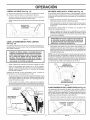
El contacto de la mano con el impulsor giratorio al interior
del conducto de descarga es la causa mils comL_n de
lesiones con las mfiquinas quitanieve. Nunca usar las
manos para limpiar el conducto de descarga. Para limpiar
el conducto:
1.
iAPAGAR EL MOTOR!
2.
Esperar 10 segundos para asegurarse de que las hojas
del impulsor hayan parado de girar.
3.
Usar siempre una herramienta para limpiar, nunca las
manos.
Mantenimiento
No hacer funcionar el motor al interior, excepto en la
puesta en marcha y para transportar la mfiquina quitanieves dentro o afuera del edificio. Abrir las puertas que
dan al exterior; los gases de escape son peligrosos.
Tener mucho cuidado cuando se trabaja en terrenos
pendientes.
12. No conducir la mfiquina demasiado rfipidamente sobre
superficies resbaladizas. Mirar atrfis y ser prudente
durante la marcha atrfis.
Limpiar un conducto
Cuando se limpie, repare o inspeccione la mfiquina,
cerciorarse de que todos los mandos est@n desconectados y que la colector /impulsor y todas las partes
m6viles est@n paradas. Desconectar el cable de la
buj[a de encendido y mantener el cable lejano de la
buj[a de encendido para prevenir puestas en marcha
accidentales.
8.
11. No sobrecargar la capacidad de la mfiquina intentando
despejar nieve a una velocidad demasiado alta.
16. Nunca tocar un motor o un silenciador
calientes.
Despu@s de golpear un objeto ajeno, parar el motor,
quitar el cable de la bujia de encendido, desconectar el
cable de los motores el6ctricos, inspeccionar a fondo
la mfiquina quitanieves para detectar da_os y repararlos antes de volver a encender y utilizar la mfiquina
quitanieves.
4.
10. No dirigir nunca la eyecci6n hacia personas o 6.reas
donde se pueden producir da_os. No permitir que los
nitros se acerquen.
22
y conservaci6n
1.
Controlar frecuentemente que el perno de cizalla y
los demfis pernos est@n adecuadamente apretados
para asegurar que la mfiquina puede trabajar con
seguridad.
2.
No dejar nunca la mfiquina quitanieves con carburante
en su dep6sito dentro de un edificio donde hayan fuentes de ignici6n, como agua caliente y calentadores de
ambiente o secadoras de ropa. Dejar enfriar el motor
antes de guardar la mfiquina al interior.
3.
Hacer siempre referencia a la gu[a de instrucciones del
operador para detalles importantessi se tiene que guardar la mfiquina quitanieves por un largo periodo.
4.
Mantener o sustituir las etiquetas de seguridad e instrucci6n, si fuera necesario.
5.
Hacer funcionar la mfiquina quitanieves por algunos
minutos despues de lanzar nieve, para limpiar la
mfiquina y prevenir el congelamiento de la colector /
impulsor.
GARANTiA
LIMITADA
DE 2 ANOS
DEL LANZADOR
DE NIEVE CRAFTSMAN
Siempre que se Io utilice y se Io mantenga de acuerdo alas instrucciones del manual del usuario, si este lanzador de
nieve Ilega a fallar debido a un defecto de los materiales o de fabricaci6n dentro de los dos a_os posteriores a la fecha de
compra, Ilame al 1-800-4-MY-HOME®
para gestionar su reparaci6n sin cargo.
Durante los primeros 30 dias de dicho plazo, se le brindar& el servicio a domicilio sin costo. Para su conveniencia,
tambi6n podr& disponer del servicio a domicilio despu_s de los primeros 30 dias, pero se le cobrar& un vi&tico. El mismo
no ser& aplicable si usted Ileva la unidad a un centro autorizado de Craftsman. Para saber cu&l le queda m&s cerca, Ilame
al 1-800-4-MY-HOME®
La cobertura
de la presente
. Aquellos elementos
pernos del cortador
Garantia
. El servicio de mantenimiento
. El cambio
no incluye:
perecederos que se desgastan
y las correas.
o reparaci6n
por el uso habitual, incluidos,
de manera no taxativa,
las bujias, los
est&ndar, los cambios de aceite o los afinados.
de neum&ticos
pinchados
por objetos extranos,
tales como clavos,
espinas, troncos o vidrios.
. Aquellas reparaciones que deban hacerse por problemas derivados de mal uso por parte del operador, incluidos, de
manera no taxativa, danos causados por el impacto de objetos que tuerzan el bastidor, el eje del cigOer_al o la barrena,
o bien por exigir demasiado al motor.
. Aquellas reparaciones que deban realizarse por problemas derivados de negligencia por parte del operador, incluidos,
de manera no taxativa, los daSos que se produzcan por guardarlo en condiciones inapropiadas,
el no utilizar aceite de
motor del grado adecuado yen la cantidad correcta, o bien el no mantener el equipo de acuerdo a las instrucciones del
manual del usuario.
. Aquellas limpiezas o reparaciones que se le deban hacer al motor (sistema de combustible) toda vez que se determine
que el combustible estaba contaminado
u oxidado (en mal estado). En general, se debe utilizar el combustible dentro
de los 30 dias posteriores a su compra.
. El deterioro
y desgaste
normales
de las terminaciones
exteriores
o el reemplazo
La presente garantia
ser& v&lida por solo 90 dias en caso que el equipo sea utilizado
La presente
solo ser& v&lida mientras el equipo permanezca
garantia
La presente garantia le otorga derechos
varian de un estado a otro.
Sears, Roebuck
legales especificos.
de la etiqueta del equipo.
para fines comerciales
dentro del territorio
de los Estados
o de alquiler.
Unidos.
Puede que usted tenga tambi6n otros derechos,
los cuales
and Co., Hoffrnan Estates, IL 60179
ESPECIFICACIONES
FELICITACIONES por la compra de su M_.quina Quitanieves.
Ha sido disehado, planificado y fabricado para darle la mejor
confiabilidad y et mejor rendimiento posibte.
En et caso de que se encuentre con cualquier problema que
no pueda sotucionar fa.cilmente, haga el favor de ponerse en
contacto con un Centro de Piezas y Reparaci6n Sears o con
un otro centro de servicio cualificado. Cuenta con tecnicos
bien capacitados y competentes y con las herramientas adecuadas para darle servicio o para reparar este unidad.
Haga el favor de leer y de guardar este manual. Estas instrucclones le permitir_.n montar y mantener su unidad en forma
adecuada. Siempre observe las "REGLAS DE SEGURIDAD."
Capacidad y
Tipo de Gasolina:
3.0 Cuartos
Regular sin Plomo
Tipo de Aceite
(API SG-SL):
SAE 5W-30 o 10W-30
Sintetico SAE 5W-30
Capacidad
18 Onzas
Bujia:
Abertura:
NOMERO
DE SERIE:
FECHA DE COMPRA:
de Aceite:
Champion RJ19LM
0.030"
RESPONSABILIDADES
EL NUMERO
DEL NODELO
Y EL DE SERIE SE
ENCUENTRAN
EN LA CALCOMANIA
ADJUNTA A LA
PARTE TRASERA DE LA CAJA DE LA MAQUINA QUITANIEVES.
DEL PRODUCTO
DEL CLIENTE
• Lea y observe las reglas de seguridad.
• Siga un programa regular de mantenimiento, cuidado y uso
de su M&quina Quitanieves.
• Siga las instrucciones descritas en las secciones "Mantenimiento" y '_,tmacenamiento" de este Manual det Due_o.
DEBE REGISTRAR
TANTO EL NUMERO DE SERIE
COME LA FECHA DE COMPRA Y MANTENGALOS EN
UN LUGAR SEGURO PARA REFENCIA EN EL FUTURO.
23
PARTES EMPACADAS
POR SEPARADO EL LA CAJA DE CARTON
(1) PAQUETE DE
ESTABI LIZADOR
(1) MULTILLAVE
DEL COMBUSIBLE
(180684)
FRESH
(1) LLAVE DE
IGNJCJON DE
(1) CABLE DE
ALIMENTACION
SEGURiDAD
(198563)
(193071)
_===_Z_IIIIIII
(1) BIELA
--
(1) CONDUCTO
LA DESCARGA
(1) BIELA
DE MANDO
DE MANDO
DE TALADRO
DE TRACClON
_1111111
PERNOS Y TURCAS EXTRA PARA LA CIZALLA
©
(2) PERNO DON
RESALTO 1/4-20 × 1-3/4
(2) TUERCAS DE
SEGURiDAD
1/4-20
(192090)
(73800400)
SOPORTE DE CABEZA GIRATORIA
(3) RESORTES
DE RETENCION
(169675)
(1) ARANDELA
(19131316)
3/8
(1) TUERCA DE
SEGURIDAD
3/8
(73800600)
MANDO A D|STANC|A DEL DEFLECTOR DEL CONDUCTO
(1) TUERCA DE
SEGURIDAD
(1) PERNO DE
ACARREO
(1) TUERCA DE
SEGURIDAD
5/16-18
5/16-18 × 5/8
1/4-20
(751153)
(72250505)
(1) ARANDELA
DE NILON
(179246)
(1) PERNO DON
RESALTO 1/4-20
(1) RESORTE
(184505)
(179829)
(191730)
7
I
I
I
(2) ARANDELAS
PLANAS
(2) PERNO DE
ACARREO
3/8-16 × 2.25
(2) MANEJE LAS
PERJLLAS
I
]
24
f
MONTAJE / PRE-OPE
Leer estas instrucciones y este manual completamente antes
de empezar a montar o hacer fu ncionar su nuevo quitanieves.
La lectura del manual le familiarizara con la unidad, Io cual
le asistira en el montaje, la operaci6n y el mantenimiento
del producto.
BIELA DE
MANDO
Su nuevo quitanieves se ha montado en la fa.brica excepto aquetlas partes que se han dejado sueltas por motivos de transporte.
Todas las partes como las tuercas, arandelas, pernos, etc., necesarias para completar et ensamblaje se haltan en la bolsa de
las partes. Para asegurar un funcionamiento seguro y adecuado
de su quitanieves, todas estas partes que usted ensamblar& han
de apretarse muy bien. Usar las herramientas correctas que
aseguren et apriete adecuado.
SACAR LA MAQUINA
DEL CARTON
ACION
EMPUI_ADURA
SUPERIOR
POMO ELA
EMPUI{IADURA
QUITANIEVES
INFERIOR
1. Sacar todas las partes suettas y las cajas de partes det
cart6n.
2. Cortar los cuatro _.ngutos det cart6n y apoyar los panetes en
horizontal.
3. Desmontar los dos (2) tornitlos que sujetan et bastidor det
barrenas a la plataforma.
4. Quitar todos los materiales de empaquetamiento excepto el
lazo de pla.stico que sujeta la bieta det control de vetocidad a
la empufladura inferior.
5. Desmontar los dos (2) lazos de pl_.stico que sujetan et empufladura superior a la plataforma.
6. Sacar la m_.quina quitanieves det cart6n y controlar a fondo
que no se hayan quedado en et cart6n partes adicionales
suettas.
FIG. 1
COMO PREPARAR SU
MAQUINA QUITANIEVES
PORTAHERRAMIENTAS
BIELA DE MANDO
LA VELOCIDAD
RESORTE DE
RETENCI6N
(Vet Fig. 10)
Con su m_.quina quitanieves se le proporciona un portaherramientas. El portaherramientas esta. situado sobre la cubierta de
la correa. Guarde los pernos de cizalla de recambio, tuercas y
Ilave de tuercas en la botsa de partes det portaherramientas.
NOTA: La Ilave de apriete se puede usar para montar la cabeza
giratoria del conducto a la m&quina quitanieves y para hacer
regutaciones de las ptacas de deslizamiento.
DESPLEGAR
LA EMPUNADURA
SUPERIOR
SOPORTE MANDO
DE LA VELOCIDAD
1. Atzar la empufladura superior hasta la posici6n de operaci6n
y apretar fuerte el pomo de la empufladura.
MONTAR LA BIELA
DEL CONTROL
DE VELOCIDAD
PALANCA DE MANDO
DE LA VELOCIDAD
(Vet Figs. 1 y 2)
FIG, 2
1. Quitar et lazo de pl_.stico que sujeta la biela a la empufladura
inferior. La botsa de piezas contiene tornillos, arandelas y
pomos adicionales. Utilice estos etementos para fijar el mango
superior al inferior. Inst&letos en los orificios inferiores de los
mangos.
2. Montar la bieta en el soporte det control de vetocidad y apretar
con et resorte de sujeci6n.
25
f
MONTAJE / PRE-OPERACI
MONTAJE DE LA BIELA
DE IVlANDO DE LA TRACCION
MONTAR LA BIELA
DE MANDO DE LA BARRENA
(Vet Figs. 3 y 4)
(Vet Figs. 5 y 6)
La bieta de mando de la tracci6n tiene un gancho largo en et
extremo det resorte, como mostrado.
La biela del mando de tracci6n tiene un gancho corto en la extremidad det resorte, como mostrado.
1. Destizar et manguito de caucho sobre la bieta y enganchar la
terminaci6n det resorte en el soporte det pivote con et gancho
abierto hacia abajo como mostrado.
1. Deslizar el manguito de caucho sobre la bieta y enganchar
la terminaci6n del resorte al brazo de mando con et gancho
abierto hacia arriba como mostrado.
2. Con la extremidad superior de la bieta cotocada debajo del
lado izquierdo det panel de control, empujar la biela hacia
abajo e insertar el extremo de ta bieta en el orificio det soporte
det control. Apretar con et resorte de sujeci6n.
2.
BIELA
Con el extremo superior de la biela colocado debajo del lado
derecho del panel de control, empujar la biela hacia abajo
e insertar et extremo superior de la bieta en et orificio en el
soporte de mando de la barrena. Apretar con et resorte de
sujeci6n.
DE MANDO
MANDO DE
LABARRENA_
BIELA DE
MANGUITO
CAUCHO
'__I
DE
BRAZO DE
MANDO
SOPORTE
PIVOTE
FIG. 3
PALANCA DE
MANDO DE
TRACCI6N
FIG. 5
BIELA DE
MANDO
DE LA
BARRENA
RESORTE DE
RETENCI6N
RESORTE
DE RETENCION
SOPORTE
DE MANDO
DETRACCION
PALANCA
MANDO
BARRENA
SOPORTE
MANDO
BARRENA
FIG. 4
FIG. 6
26
f
MONTAJE / PRE-OPE
ACION
MONTAR EL CONDUCTO DE EYECCION / CABEZA
GIRATORIA
DEL CONDUCTO
(Ver Fig. 7)
MONTAR EL MANDO A DISTANCIA DEL DEFLEC=
TOR DEL CONDUCTO
(Ver Figs. 8 y 9)
NOTA: la Ilave de apriete proporcionada en su botsa de partes se
puede utilizar para instalar la cabeza giratoria del conducto.
1. Acoplar et soporte del cable remoto al conducto de eyecciSn
con un perno de madera de 5/16-18 y una contratuerca de
5/16-18 como mostrado. Apretar firmemente.
1. Cotocar el grupo del conducto de eyecci6n sobre la base det
conducto con la abertura de eyecci6n hacia et frente de la
m&quina quitanieves.
2. Montar et ojal met&lico del cable remoto al deflector del conducto con un perno de cotlar[n de 1/4-20, una arandela de
nylon, una arandela plana y una contratuerca de 1/4-20 como
mostrado. Apretar firmemente.
2. Posicionar la cabeza giratoria del conducto sobre el soporte del
conducto. Si fuera necesario, girar et grupo del conducto para
alinear ta escuadra y ta ctavija debajo de la cabeza giratoria
del conducto con los orificios en et soporte det conducto.
3. Colocar resortes de gancho entre las tuercas hexagonales en
la cabeza giratoda del conducto y en el odficio det deflector
det conducto, como mostrado.
3. Con ta cabeza giratoria det conducto y el soporte det conducto
alineados, posicionar la cabeza giratoria del conducto sobre
la ctavija y et perno con filete det soporte de montaje.
4. Colocar una arandeta y una contratuerca de 3/8 sobre et perno
con filete y apretar firmemente.
ALINEE CABEZA GIRATOR|A
DEL CONDUCTO Y
SOPORTE ANTES
DE APRETAR LA
CONTRA-TUERCA
_
kL-_-_
_
RESORTE
1/4-20
PERNO DE
COLLARiN
DEFLECTOR
DEL
CONDUCTO
ARANDELA
DE NYLON
3/8
CONTRATUERCA
1/4-20
CONTRATUERCA
3/8 ARANDELA
5/le-18
PERNO DE
MADERA
OJAL
DEL
CABLE
J
OPORTE
CLAVIJA
LCABLE
REMOTO
PASADOR
ROSCADO
SOPORTE
CONDUCTO
CABEZA GIRATORIA
DEL CONDUCTO
5/16-18
CONTRATUERCA
FIG, 8
SOPORTE
CABEZA
GIRATORIA
FIG. 7
PALANCA DE MANDO
DELDEFLECTOR DE CONDUCTO
FIG, 9
CONTROLAR
LA PRESION
DE LOS NEUMATICOS
Los neum&ticos de su m&quina quitanieves se han inflado m&s
de to normal por motivos de envio. Una correcta e igual presi6n
de los neum&ticos es importante para la mejor prestaci6n en et
despeje de nieve.
*
27
Reducir la presi6n de neum&ticos a 14-17 PSI (19-24.5 N-m).
OPERAC
FAMILIARJCESE
CON SU MAQUINA
f
QUITANIEVES
LEA ESTE MANUAL DEL DUENO Y LAS REGLAS DE SEGURIDAD
ANTES DE OPERAR SU Mi_QUINA QUITANIEVES.
Compare las ilustraciones con su segadora para familiarizarse con ta ubicaci6n de los diversos controles y ajustes. Guarde este manual
para referencia en et futuro.
Estos sJmbolos pueden apareser
comprenda sus signJficados.
sobre su m_quJna quJtanJeves
o en la literatura proporcionada
con el producto,
Aprenda
y
I\1 It¢
PELIGRO o
ATENCION
MOTOR
APAGADO
MOTOR
ENCENDIDO
;
RAPIDO
F R
COMBUSTIBLE
ACEITE
DALANTERO
REVI_S
LLAVE DE IGNICION,
INTRODUCIR PARA
PONER EN MARCHA,
EXTRAER PARA APAGAR.
DESEN=
GANCHADO
iENGANCHADO,
DESCARGA
DE LA NIEVE
LENTO
M
MANDO DE
LATRACCION
28
ESTRANGULACION
CEBADOR
LEER Y SEGUIR
TODAS
LAS
INFORMACIONES
DE SEGURIDAD
ANTES
DE USAR
ESTE
PRODUCTO.
GUARDAR
ESTAS INSTRUCCIONES
PARA CONSULTAS
FUTURAS.
PERACl
MANGO DE
RETROCESO DE
DEPOSITO
DE GASOLINA
f
PALANCA
DE CONTROL
PALANCA
PALANCA DE
DE
CONTROLDELA
VELOCIDAD DE
MANGO DE CONTROL
DE LA
GUiA
RETROCESO
DE BARRENA
{RANQUE
X
SILENCIADOR
CONTROL
DE LA
ESTRANGULACION
DEL CONDUCTO
PALANCA DECONTROLDEL
DEFLECTOR A DISTANCIA
PALANCA
DE
DEFLECTOR DE
DESCARGA
CEBADOR
LLAVE DE
ENCENDIDO
SEGURIDAD
DE EYECCION
CONTROL
DELA
GUiA CON
TRACCION
3ATILLO
DE
VUELTA A
IZQUIERDA
DE
CONDUCTO
DESCARGA
DE_
INTERRUPTOR
DE ON/OFF
LUZ
HERRAMIENTA
MANILLA
DEL MANGO
PARA LIMPIAR
SILENCIADOR
NOTA:LAS
PARTES
MOSTRADAS ARRIBA
SE ENCUENTRAN EN
SU TiPICA POSICION
EN EL MOTOR. LA
POSICION REAL
PUEDEVARIAR
DEPENDIENDO
DEL MOTOR EN
SU UNIDAD.
CORTADOR
DE
FIG. 11
PLACASDE
CUMPLE CON LOS REQUISITOS
DE SEGURIDAD
DE LA A.N.SJ.
Nuestras m_quina quitanieves cumplen con los est_ndares
de seguridad del American
National Standards
Institute.
Llave de encendido de seguridad-tiene
que introducirse para
que el motor arranque y funcione. Quitese cuando no se usa la
maquina quitanieves.
Bot6n de arranque el_ctrico - utilizado para poner en marcha
et motor.
Palanca de control de la velocidad de guia - utilizada para
seleccionar la marcha adetante o atr&s y la vetocidad de la
m&quina quitanieves.
Mango de retroceso (auxiliar) de arranque - utilizado para
poner en marcha et motor.
Cebador - bombea m&s carburante desde et carburador al
cilindro para arranques con et motor frio.
Palanca de control de la guia con tracci6n - utilizada para
accionar et movimiento propulsado de potencia adetante o
marcha atr&s de la m&quina quitanieves.
Control de la estrangulaci6n
motor frio.
Interruptor
motor.
Palanca de control del conducto
de eyecci6n - utilizada
para cambiar la direcci6n de lanzamiento
de la nieve.
- utilizado para arrancar con
Palanca de control del deflector a distancia
regular la distancia a la que se lanza la nieve.
Palanca de control de la barrena - utilizada para conectar et
movimiento de la barrena (lanza nieve).
Portaherramientas
- utilizada para guardar
tuercas de recambio y llave de tuercas.
Gatillos de vuelta a izquierda
dirigir la m&quina quitanieves.
y derecha
- utilizada para
Placas de deslizamiento
- utilizada para regular la altura de la
barra de arrastre del sueto.
pernos varios y
- utilizados
de ON / OFF - utilizado para parar (STOP) et
Cortador de acumulaciones
acumutaciones de nieve.
para
29
- usado para cortar a traves de
OPE
f
ACION
CONTROLAR
La operaci6n de cualquier m&quina quitanieves
puede hacer que salten objetos extraflos dentro
de sus ojos, Io que puede producir daflos graves
en estos. Siempre use anteojos de seguridad
o protecci6n para los ojos mientras opere su
m&quina quitanieves o cuando haga ajustes o
reparaciones. Recomendamos gafas o una mascara de seguridad de visi6n amptia de seguridad usada sobre las gafas.
COMO
UTILIZAR
SU M._QUINA
o pot material lanzado desde el conducto
de
eyecci6n.
Mantenergraves
siempre
6tea de
eden
causar heridas
pot elcontacto,
operaci6n
libre de toda persona, niflos
pequeflos y animales dom6sticos,
incluso
durante la puesta en marcha.
QUITANIEVES
Si el conducto de descarga o la barrena se atascan,
apagar el motor y espera que las partes en movimiento
se hayan parado. Usar la herramienta de limpieza, NO
LAS MANOS, para liberar el conducto y/o la barrena.
PARARSE
GU[A CON TRACCION
Soltar la patanca de control de gufa a tracci6n para parar
et movimiento hacia detante o marcha atr&s de la m&quina
quitanieves.
BARRENA
La DIRECCION en ta que se lanza la nieve se controla mediante
la palanca det mando det conducto de eyecci6n.
Para cambiar la posici6n del conducto de eyecci6n, empujar
hacia abajo la palanca det mando del conducto de eyecci6n y
mover la palanca hacia la izquierda o la derecha hasta que el
conducto este en la posici6n deseada. Cerciorarse de que la
palancase suette yse quede btoqueada en ta posici6n deseada.
Soltar la palanca de control de la barrena para parar de lanzar
nieve.
MOTOR
1. Poner et interruptor de ON / OFF en la posici6n de "OFF".
de seguridad
La DISTANCIA a la que se lanza la nieve se controta mediante
la posici6n del deflector del conducto. Colocar et deflector bajo
para lanzar nieve a breve distancia; colocarlo m&s alto para
lanzar la nieve m&s tejos.
para
NOTA: No usar nunca et cebador para parar et motor.
USAR
EL CONTROL
DE LA NIEVE
ADVERTENCIA: Las m6quinas quitanieves
tienen partes giratorias expuestas, que pu-
Conozca como hacer funcionar todos los mandos antes de afladir
carburante o intentar poner en marcha et motor.
2. Quitar (sin girar) la Ilave de encendido
prevenir un uso no autorizado.
LA EYECCION
(Vet Fig. 12)
$EGURIDAD
Presionar hacia abajo la palanca de mando del deflector det
conducto y mover la palanca hacia adelante para bajar et
deflector y disminuir la distancia. Mover la patanca det mando
del deflector del conducto hacia atr&s para alzar et deflector
y aumentar la distancia. Asegurarse de que la palanca vaya
atr&s y fijarla en la posici6n deseada.
DE LA ESTRANGULACION
(Vet Fig. 11)
El mando det cebador est& en el motor. Utilizar et mando det
cebador siempre que se arranque con motor frio. No utilizar para
poner en marcha un motor caliente.
* Para conectar et cebador, girar el mando en et sentido inverso
de las agujas del retoj. Para desconectar, girar et mando poco
a poco en el sentido al de las agujas det retoj.
PALANCA DE CONTROLDEL
CONDUCTO DE EYECCION
/
/
/
/// /,/
/
OERRADA
I\1ESTRANGOLAO,6N
PALANCA DECONTROL
DELDEFLECTOR
A DISTANCIA
FIG. 12
FIG. 11
30
OPERAC
LANZAR
f
IVIOVERSE
LA NIEVE (Vet Fig. 13)
ADELANTE
Y ATRAS
(Vet Fig. 15)
*
Apretar la palanca de mando de la barrena hacia la empufladura para conectar la barrena y lanzar nieve.
El movimiento AUTO-PROPULSADO,
hacia adetante y marcha
atrAs de la m&quina quitanieves, se controta mediante la palanca
de mando de la guia de tracci6n posicionada en la empufladura
izquierda.
*
Soltar la palanca de mando de la barrena para parar de lanzar
nieve.
Apretar la patanca de mando de la guia de tracci6n hacia la
empufladura para conectar et sistema de guia.
La rotaci6n de la barrena se controla con ta palanca de mando
de la barrena posicionada en la empufladura derecha.
PALANCA
CONTROL
Soltar la palanca de mando de la guia de tracci6n para parar
el movimiento hacia detante o marcha atr&s de la m&quina
quitanieves.
DE
VELOCIDAD y DIRECCION se controlan
mando de vetocidad de guia.
con la 3alanca det
Mover la palanca del mando de la velocidad en la posici6n
deseada ANTES de conectar la palanca det mando de guia
de tracci6n. Asegurarse de que la palanca vaya atr&s y fijarla
en la posici6n deseada.
ATENCION: No mover la palanca del mando de
la velocidad cuando la palanca del mando de
la guia de tracci6n esta conectada. Esto puede
perjudicar la m_quina quitanieves.
FIG. 13
USAR
LA HERRAMIENTA
PARA LilVIPIAR
(Vet Fig. 14)
En ciertas condiciones de la nieve, et conducto de descarga puede atascarse con hieto y nieve. Usar la herramienta de limpieza
para quitar et btoqueo.
*
Cuando ae limpia, repara o se inspecciona la
m_guina, asegurarse de que todos los mandos
eaten desconectados y que la barrena/impul=
sot y todas las partes que se mueven est_n
parados. Desconectar el cable de la clavija y
mantener el cable alejado de la bujia para evitar
una puesta en marcha accidental.
•
Sottar la patanca de mando de la barrena y apagar el motor.
•
Quitar la herramienta para limpiar de su clip de soporte.
Agarrar la herramienta de modo firme pot la empufladura y
empujar y girar la herramienta en et conducto de descarga
para etiminar et atasco.
Despues de eliminar la nieve acumulada, votver
herramienta en su clip empujAndolo en et clip.
•
•
Velocidades m&s lentas son para nieve mAs pesada y veIocidades m&s altas para nieve ligera y para transportar la
mAquina quitanieves. Se recomienda usar una velocidad m&s
baja hasta que se este acostumbrado a las operaciones de
la m&quina quitanieves.
NOTA: Cuando ambas palancas de mando de la guia de tracci6n
y de la barrena esten conectadas, la palanca del mando de guia
de tracci6n bloquear& la palanca de mando de la barrena en ta
posici6n de conexi6n. Esto permitirA sottar la mano derecha de
la empufladura y regular la direcci6n det conducto de eyecci6n
sin interrumpir et proceso de lanzamiento de la nieve.
PALANCA DE
CONTROLDELA
CONTRACCION
a colocar la
//
//
Asegurarse de que et conducto de descarga este dirigido hacia
una direcci6n segura (no vehiculos, edificios, personas u que
otros objetos esten en la direcci6n de la descarga) antes de
poner en marcha el motor.
PALANCA
DE CONTROL DE LA
VELOCIDAD DE GUiA
Volver a poner en marcha el motor, luego oprimir la palanca
de mando de la barrena hacia la empufladura para limpiar la
nieve det alojamiento de la barrena y et conducto de descarga.
CONDUCTO
DESCARGA
FIG. 15
FUNCIONAMIENTO
DE
DE LA DIRECCION
(Vet Fig. 16)
Los activadores de direcci6n se utilizan para ayudar a dirigir su
m&quina quitanieves. Los activadores est&n posicionados en la
parte inferior de cada empufladura. Cuando se aprieta un activador, se desconecta la rueda motriz de aquel tado de la m&quina
quitanieves y esto permite girar en esa direcci6n.
HERRAMIENTA
PARA LllVlPIAR
•
Para girar hacia la izquierda, apretar et activador del lado izq.
•
Para girar hacia la derecha, apretar et activador det lado dcha.
ACTIVADOR
VUELTA A
IZQ.
CLIP DE SOPORTE
FIG. 14
31
ACTIVADOR
VUELTA A
DCHA.
FIG, 16
OPE
REGULAR
LAS PLACAS
f
ACION
DE DESLIZAMIENTO
BASTIDOR DEL
BARRENAS
(Vet Fig. 17)
NOTA: la Ilave de apriete proporcionada en su bolsa de partes
puede utitizarse para regular las ptacas de deslizamiento.
Las placas de deslizamiento est&n posicionadas a cada lado
del alojamiento de la barrena y regutan la distancia entre la
barra de arrastre y et suelo. Regute las placas de deslizamiento
uniformemente a la altura apropiada a las condiciones de la
superficie. Para despejar nieve en condiciones normales, como
en vias de acceso adoquinadas o aceras, meter los placas de
destizamiento en la posici6n m&s alta (menor distancia de barrido) para dar una distancia de 1/8" entre la barra de arrastre y
et sueto. Utilizar una posici6n intermedia si la superficie que se
debe despejar no es uniforme.
CORTADORE DE
POSICI6NDE_
ALMACEN_
1.
"
/ _J,P
DE PONER
EN MARCHA
1. Controlar et aceite det motor con ta m&quina quitanieves sobre
un terreno llano.
2. Sacar ettap6n/varilla de nivel del relleno de aceite y limpiarla,
votver a porter lavarilla y enroscar el tap6n firmemente, esperar
algunos segundos, sacar la varilla y leer el nivet de aceite. Si
fuera necesario, ahadir aceite hasta Ilegar a la marca "FULE'
(lleno) en la varilla. No Ilenar demasiado.
2. Regular los placas de deslizamiento destornillando tan los
tuercas, seguidamente mover la placa de deslizamiento en
la posici6n deseada. Asegurarse de que las dos ptacas esten
regutadas uniformemente. Apretar firmemente.
*
BASTIDOR
DEL BARRE=
NAS
Para cambiar el aceite del motor, ver "COMO CAMBIAR EL
ACEITE DEL MOTOR" en la secci6n de Mantenimiento de
este manual.
CONTROL
DE LA ESTRANGU-
BARRA DE
TAPA DEL DEPOSITO DE ACEITE DEL
MOTOR CON VARILLA INDICADORA
DE NIVEL
TAPA DEL
DEPOSITO
DE
LACION
PLACA DE
DESLIZAMIENTO
BAJA (DISTANCIA
EL MOTOR
CONTROLAR EL NIVEL DE ACEITE DEL MOTOR
(Vet Fig. 19)
El motor de su m&quina quitanieves viene de la f&brica ya Ileno
de aceite.
Apagar et motor y esperar a que todas tas partes en movimiento
se hayan parado.
POSICI6N
TUERCA
DE AJUSTE
FIG. 18
ANTES
Si se tiene que utilizar ta m&quina quitanieves sobre una
superficie de gravilla, cerciorarse de que las placas de deslizamiento esten regutadas en la posici6n m&s baja (mayor
distancia de barrido.
POSICI6N
(DISTANCIA
BAJA DESDE
EL SUELO)
II
o
LACIONES
NOTA: No hacer funcionar la m&quina quitanieves sobre gravitla
o superficies rocosas. Objetos como gravilla, piedras u otros
escombros, pueden ser f&cilmente recogidos y lanzados por et
imputsor, Io que puede causar heridas personales graves, dahos
a propiedades o a la m&quina quitanieves.
•
"_//, /
BOTON DE
ARRANQUE
ELEC-
ALTA DESDE EL SUELO)
FIG. 17
BARRA
DE ARRASTRE
(Vet Fig. 17)
La barra de arrastre no se puede regular, pero es reversible.
Despues de un uso muy prolongado, puede desgastarse. Cuando
se haya consumido casi hasta et borde del alojamiento, se puede
usar por el otro lado, pudiendota utilizar por m&s tiempo antes de
que sea necesario un recambio. Sustituir una barra de arrastre
dahada o desgastada.
USAR LOS CORTADORES
MANGO
DE RETROCESO (AUXILIAR) DE
ARRANQUE
LLAVE DE
ENCENDIDO DE
SEGURIDAD
DE ACUIVIULACIONES
(Vet Fig. 18)
Usar los cortadores de acumulaciones para cortar a traves de
acumulaciones de nieve que son m&s altas que la parte frontal
det quitanieves.
•
•
INTERRUPTOR DE ON/OFF
NOTA, TODAS LAS
PARTES SE MUESTRAN EN SU POSICI6N TiPICA. LA POSICl6N
REAL PUEDE CAMBIAR SEGUN EL MOTOR DE SU UNIDAD.
Aftojar latuerca de ajuste superior para permitir que el cortador
de acumutaciones suba hasta la posici6n m&s alta y apretar
firmemente. Repetir para et lado opuesto det quitanieves.
FIG. 19
Cuando no se usan los cortadores de acumulaciones, aftojar
la tuerca de ajuste, bajar hasta la posici6n de almacenaje y
apretar la tuerca de modo seguro.
AGREGUE
•
32
GASOUNA
(Vet Fig. 19)
Llene el estanque de combustible hasta la parte inferior
del cuetto de relteno del estanque de gasolina. No Io Ilene
demasiado. Use gasolina regular, sin plomo, nueva y limpia
con et m[nimo de 87 octanos. No mezcle et aceite con la
gasolina. Para asegurar que la gasolina utilizada sea fresca
compre estanques los cuales puedan ser utilizados durante
los primeros 30 dias.
f
OPERAC
PUESTA
EN IVIARCHA DEL MOTOR
5. Tirar la empufladura det arrancador de retroceso r&pidamente.
No sottar de gotpe la cuerda del arrancador.
El motor de su m&quina quitanieves est& equipado tanto con un
arrancador electrico de 120 Voltios A.C. como con un arrancador
de retroceso. El arrancador etectrico est& equipado con un cable
de potencia de tres hilos y un enchufe y est& proyectado para
que funcione con corriente domestica de 120 Vottios A.C.
*
6. Cuando et motor arranca, sottar la empufladura det arrancador de retroceso y mover lentamente et mando det obturador
hasta la posici6n OFR
Dejar que el motor se caliente por algunos minutos. Et motor no
proporcionar& la plena potencia hasta que no haya alcanzado
la temperatura normal de funcionamiento.
AsegQrese que la instalaci6n etectrica de su casa sea un
sistema de tres hilos puesta a tierra de 120 Voltios A.C. Si
no est& seguro, consutte un etectricista autorizado.
&
PUESTA EN MARCHA CON EL MOTOR CALIENTE ARRANCADOR DE RETROCESO
ADVERTENCIA: No use el arrancador
el_ctrico si la instalaei6n el@ctrica de
su casa no es un sisterna de tres hilos
puesta a tierra de 120 Voltios A.C. Po=
drian resultar heridas personal graves
o da_os a su rn_quina quitanieves.
Seguir los pasos descritos arriba, manteniendo el mando det
obturador en la posici6n OFR NO pulsar el cebador.
ANTES
DE PARAR
Hacer funcionar el motor por algunos minutos para ayudar a
secar toda humedad det motor.
PUESTA EN MARCHA CON EL MOTOR FRIO
- ARRANCADOR ELE_CTRICO
SI EL ARRANCADOR
LADO
DE RETROCESO
SE HA CONGE-
1. Insertar la tlave de encendido de seguridad (embalado separado en bolso de tas piezas) en la posici6n de encendido hasta
que haga un ruido seco. NO girar la llave. Guardar la llave de
encendido de seguridad de recambio en un lugar seguro.
Si el arrancador de retroceso se ha congetado y no pone en
marcha et motor, hacer Io siguiente:
2. Poner et interruptor de ON / OFF en la posici6n de "ON".
2. Sottar la empufladura det arrancador
ir contra et arrancador.
1. Coger la empufladura del arrancador de retroceso ytirar lentamente cuanta m&s cuerda sea posibte fuera det arrancador.
3. Girar el mando det obturador en la posici6n FULL.
de retroceso y dejarla
Si aun asi et motor no arranca, repetir los pasos descritos arriba
o utilizar et arrancador electrico.
4. Conectar et cable de potencia al motor.
5. Enchufar ta otra extremidad det cable de potencia en un enchufe de tres hitos con puesta a tierra de 120 Voltios A.C.
CONSEJOS
NOTA: No usar el cebador cuando se pone en marcha et motor
con et arranque etectrico.
PARA LANZAR
LA NIEVE
*
Ir m&s tentamente en nieve alta, hetada ofuertemente mojada.
Para regular lavelocidad con respecto al sueto, utilizar el mando
de vetocidad de guia, y NO et interruptor de ON/OFR
*
Es m&s f&cil y eficiente despejar la nieve inmediatamente
despues de que haya cafdo.
*
7. Cuando et motor se pone en marcha, sottar el bot6n de arranque y mover lentamente et mando det obturador hasta la
posici6n OFR
Et mejor momento para despejar la nieve es temprano por la
maflana. En este momento la nieve est& normalmente seca
y no ha sido expuesta directamente al sol y a temperaturas
calientes.
®
8. Desconectar et cable de potencia antes del enchufe y despues
del motor.
Hacer coincidir cada camino sucesivo paraasegurar el despeje
de toda la nieve.
®
Lanzar la nieve sotavento siempre que sea posibte.
®
Regular las placas de destizamiento a la altura adecuada a
las actuales condiciones de la nieve. Ver "PARA REGULAR
LAS PLACAS DE DESLIZAMIENTO"
en esta secci6n det
manual.
6. Pulsar et bot6n de arranque
ende.
hasta que et motor se enci-
IMPORTANTE: No hacer girar el motor por m&s de 5 segundos
continuativamente cada vez que intente poner en marcha et motor. Esperar de 5 a 10 segundos entre cada tentativa.
Dejar que el motor se caliente por algunos minutos. Et motor no
proporcionar& la ptena potencia hasta que no haya alcanzado
la temperatura normal de funcionamiento.
PUESTA EN MARCHA CON EL MOTOR CALIENTE ARRANCADOR ELE_CTRICO
Para nieve considerablemente
pesada, reducir la anchura
del despeje de nieve sobreponiendo los caminos previos y
andando lentamente.
Seguir los pasos descritos arriba, manteniendo et mando det
obturador en la posici6n OFR
PUESTA EN MARCHA CON EL MOTOR FR[O ARRANCADOR DE RETROCESO
Mantener et motor limpio y libre de nieve durante et uso. Esto
ayudar& a hacer pasar aire y prolongar& la vida det motor.
Despues de comptetar el trabajo de despejar nieve, dejar que
el motor gire por algunos minutos para derretir nieve y hieto
que puedan estar en et motor.
1. Insertar la tlave de encendido de seguridad (embalado separado en bolso de tas piezas) en la posici6n de encendido hasta
que haga un ruido seco. NO girar la llave. Guardar la llave de
encendido de seguridad de recambio en un lugar seguro.
Limpiar a fondo toda la m&quina quitanieves despues de cada
uso y secarla para que este lista para et pr6ximo uso.
2. Poner et interruptor de ON / OFF en la posici6n de "ON".
3. Girar et mando det obturador en ta posici6n FULL.
4. Pulsar et cebador cuatro (4) veces si la temperatura est& por
debajo de los 15°F, o dos (2) veces si la temperatura est&
entre los 15 ° y los 50°R Si la temperatura est& pot encima
de los 50°R et cebador no es necesario.
NOTA: Utilizar demasiado el cebador puede ahogar el motor,
impidiendo el arranque. En caso de que se ahogue el motor,
esperar algunos minutos antes de intentar poner en marcha y
NO pulsar et cebador.
&
33
ADVERTENCIA: No hacer funcionar la
rn_quina quitanieves si las condieiones
del tiempo deterioran
la visibilidad.
Despejar nieve durante una fuerte
y ventosa tormenta de nieve puede
ofuscarles
y set peligroso para un
funcionamiento
seguro de la rn_quina
quitanieves.
NTO
M
Revisar si hay Sujetadores
Limpiar / Inspeccionar
Sueltos
el m&quina quitanieves
Cambiar / Revisar las Correas
N
Lubricaci6n
A
t/
Revisar el nivel del Aceite
M
Cambiar el Aceite del motor
Inspeccionar el Silenciador
v'
Cambiar / Revisar la Bujia
Vaciar el Dep6sito del Combustible
TABLA
RECOMENDACIONES
DE LUBRICACK)N
GENERALES
(_ SAE 5W-30
Aceite del Motor
La garantia de esta maquina quitanieves no cubre los articutos
que han estado sujetos al abuso o a la negligencia det operador.
Para recibir todo el valor de la garantia, el operador tiene que
mantener lamaquina quitanieves segOn las instrucciones descritas
en este manual. Hay algunos ajustes que se tienen que hacer
en forma peri6dica para poder mantener su maquina quitanieves
adecuadamente. At menos una vez cada estaci6n comprobar si
es necesario efectuar los ajustes descritos en las secciones de
Servicio y Ajustes de este manual.
• Una vez al aflo, cambie la bujia, limpie o cambie el etemento
del filtro de aire y revise si la cuchitla est& desgastada. Una
bujia nueva y un etemento del filtro de aire limpio/nuevo
aseguran la mezcta de aire-combustible adecuada y ayudan
a que su motor funcione mejor y que dure m&s.
• Siga et programa de mantenimiento en este manual.
NOTA: Usar solo parte originales del equipo del fabricante
(OEM) para reatizar et mantenimiento de esta unidad. No hacer
esto puede causar el funcionamiento incorrecto de la unidad y
arriesgar la salud det operador.
ANTES
DE CADA
(_) Yea "MOTOR"
en la seccion de
Mantenimiento
(_) Grasa Para
Uso General
Aceite del
USO
1. Revise et nivel det aceite del motor.
2. Revise si hay sujetadores sueltos.
3. Controtar los mando para asegurarse de que funcionen adecuadamente.
LUBRlCAClON
® Casquillo_
Grasa Barrena
Mantenga el maquina quitanieves bien lubricada
(ver la "TABLA DE LUBRICACION").
34
Puntos
Pivote
ANTE
MAQUINA
TO
A
PARA CAMBIAR EL ACEITE DEL MOTOR
QUITANIEVES
Siempre observe las regtas de seguridad cuando haga et mantenimiento.
Determinar la temperatura anticipada antes de cambiar et aceite.
Todo el aceite ha de cumptir con la clasificaci6n SG-SL de mantenimiento API.
LLANTAS
• AsegQrese que la maquina quitanieves este en una superficie
nivelada.
• El aceite se drenara mas facilmente siesta caliente.
• Recoja el aceite en un envase adecuado.
•
Mantener la presi6n adecuada en ambos neumaticos
RS.I. / 19-24.5 N-m).
(14-17
• Mantenga las Ilantas sin gasolina o aceite, que pueden daflar
la goma.
NOTA: Es posible desmontar la rueda det lado izquierdo de la
maquina quitanieves para tener un acceso mas facit al tap6n
de vacfo det aceite y para colocar un apropiado contenedor. Et
inclinar la unidad, que quedara apoyada a ta carcasa con la rueda
izquierda desmontada, ayudara avaciar et aceite atrapado dentro
et motor. (Ver"PARA DESMONTAR LAS RUEDAS" en ta secci6n
de Mantenimiento y Regutaciones de este manual).
NOTA: Para setlar los neumaticos y prevenir neumaticos desinflados a causa de perdidas tigeras, se puede comprar setlador al
efecto en el revendedor de partes local. Etsetlador para neumaticos
tambien previene grietas y corrosi6n det neumatico.
CORREAS
EN V
Controtar el deterioro y el desgaste de las correas en V despues
de 50 horas de funcionamiento y sustituir si fuera necesario. Las
correas no se pueden regular. Sustituir las correas si empiezan a
resbatar debido al desgaste. (Ver" QU ITAR ELCU BR ECOR REAS"
en la secci6n Mantenimiento y Regutaciones de este manual).
1. Quitar la Ilave de encendido de seguridad y desconecte
et alambre de la bujia y p6ngalo de modo que no pueda entrar
en contacto con esta.
2. Limpiar el area alrededor del tap6n de drenaje.
3. Remueva el tap6n de drenaje del dep6sito de aceite y drenaje
et aceite en un envase adecuado.
Las correas en V de su quitanieve tienen una construcci6n especial
y han de ser sustituidos con correas originales (OEM) disponibles
en su revendedor mas cercano. Usar otras correas no originales
puede causar heridas personales o daflar et quitanieve.
CAJA
DE ENGRANAJES
4. Vuelva a poner et tap6n de drenaje det dep6sito de aceite en
su tugar y aprieteto en forma segura.
5. Limpie todo el aceite derramado en la maquina quitanieves
yen et lado del motor.
6. Montar la rueda izquierda (si se ha desmontado para vaciar el
aceite). Asegurarse de que se cotoque el pasador de lingQete
en el orificio apropiado det eje de la rueda (Ver "PARA DESMONTAR LAS RUEDAS" en al secci6n de Mantenimiento y
Regulaciones de este manual).
7. Sacar et tap6n /varilla de nivel del dep6sito de aceite. Atenci6n
a no dejar entrar suciedad en et motor.
8. Llenar de aceite el motor atraves del tubo de lavarilla de nivet
del aceite. Verter lentamente. No tlenar demasiado. Para la
capacidad aproximada ver la secci6n "ESPECIFICACIONES
DEL PRODUCTO" de este manual.
9. Usar el indicador del tap6n / varilla de nivet det dep6sito de
aceite para controlar et nivet. Asegurarse de que et tap6n de
la varilla de nivel esta bien cerrado para una lectura precisa
del nivel. Mantener et nivet de aceite sobre la linea "FULtL'
(lteno) de la varilla de nivet.
10. Limpie todo el aceite derramado.
DE LA BARRENA
* La caja de engranajes fue ttenada en ta fabrica con tubricante
hasta et nivel. Se tiene que prestar atenci6n al lubricante s61osi
se ha efectuado un mantenimiento a la caja de engranajes.
. Si se requiere lubricante, usar s6to grasa Ronex ED #1.
SISTEMA
DE TRACCION
NO lubricar las partes de gufa dentro de la maquina quitanieves.
Las coronas dentadas, los arboles hexagonales, et disco de guia
y la rueda de fricci6n no necesitan lubricaci6n. Los rodamientos y
cojinetes estan lubricados a por vida y no necesitan mantenimiento.
ATENCION: Toda lubricaci6n
de las partes
descritas arriba puede causar contaminaci6n
de la rueda de fricci6n y da6ar el sisterna de
guia de su rn_quina quitanieves.
SILENCIADOR
MOTOR
LUBRICAClON
Inspeccione y cambie etsilenciador siesta corroido puede producir
un pe!igro de incendio y/o daflo.
BUJIA
Use solamente aceite de detergente de alta catidad clasificado con
la clasificaci6n SG-SL de servicio API. Seteccione la calidad de
viscosidad SAE seg[Sn su temperatura de operaci6n esperada.
CALIDADES
DE VISCOSIDAD
Cambie el buj[a al comienzo de cadatemporada de siega o despues
de cada 1O0 horas de operaci6n, Io que suceda primero. Et tipo de
buj[a y el ajuste de la abertura aparecen en "ESPECIFICACION ES
DEL PRODUCTO" en tasecci6n de Mantenimiento de este manual.
DE SAE
LIMPIEZA
IMPORTANTE: Para obtener et mejor rendimiento, mantenga
la caja de la maquina quitanieves sin acumutacion de suciedad
y basura. Limpin ta parte de abajo de su maquina quitanieves
despues de cada uso.
!
°F
-20
°c
0
30
-1;
32
40
;
10
GAMADE TEMPERATURAANTICIPADA
ANTES DEL PROXIMOCAMBIO DE ACEITE
AVISO: A pesar de que los aceites de muttiviscosidad (5W30,
10W30, etc.) mejoran et arranque en ctima frio, estos aceites de
muttiviscosidad van ha aumentar el consumo de aceite cuando
se usan en temperaturas sobre 32 ° R Revise el nivet del aceite
del motor mas a menudo, para evitar un posibte daflo en et motor,
debido a que no tiene suficiente aceite. Cambie et aceite despues
de 25 horas de operaci6n o por Io menos una vez al aflo si la
maquina quitanieves se utiliza menos 25 horas et aflo. Revise
et nivel del aceite del carter antes de arrancar et motor y despues
de cada cinco (5) horas de uso continuado. Apriete el tap6n del
aceite en forma segura cada vez que revise el nivet det aceite.
&
ADVERTENCIA: Quitar la Ilave de en=
cendido de seguridad y desconecte
el alambre de la bujia.
P6ngalo en
donde no pueda entrar en contacto
con 6sta.
Mantenga las superficies putidas y las ruedas sin gasolina,
aceite, etc.
35
No recomendamos et uso de una manguera de jardfn para
limpiar la maquina quitanieves a menos que et sistema electrico, el silenciador y et carburador esten tapados para evitar
que les entre et agua. Et agua en et motor puede acortar la
duraci6n de este.
ERVlCIO Y ADJUSTES
la palanca det mando de la barrena, controlar si los tornillos de
caperuza se han cortado. Para sustituir los tornitlos de caperuza
/ pernos de seguridad:
ADVERTENCIA: Para evitar lesi6nes serias, an=
tes de dar calquier servico o de hater ajustes:
1. Desconectar todos los mandos y mover et mando det acelerador en la posici6n de STOP (parado). Esperar que todas
las partes en movimiento se paren.
1. Asegurarse de que el interruptor de
ON/OFF est_ en la posici6n OFF.
2. Quitar la Ilave de encendido de segu=
ridad.
_3.
2. Quitar la Nave de encendido de seguridad y desconecte el
alambre de la bujfa. P6ngalo en donde no pueda entrar en
contacto con esta.
que
Y que
Aseg_rese
la barrenas
todas
las partes movibles
se hayan detenido
cornpletarnente.
4. Desconecte el alambre de la bujia y
p6ngalo en donde no pueda entrar en
contacto con _sta.
MAQUINA
3.
Alinear el orificio del impulsor con los orificios det eje del impulsor e instatar dos (2) nuevos tornitlos de caperuza / pernos
de seguridad de 1/4-20 x 1-5/8". Colocar contratuercas de
1/4-20 y apretar firmemente.
ATENCI6N: No sustituir. Usar solamente los
tornillos de caperuza / pernos de seguridad
originales entregados con la rn_quina quita=
nieves.
4.
Insertar la Ilave de encendido de seguridad yvuelva a conectar
et alambre de la bujia a esta.
QUITANIEVES
PARA AJUSTAR LA ALTURA
DE IVIAQUINA QUITANIEVES
1/4-20
_
1/4-20 x 1-5/8 ,
TUERCA DE //]_ TORNiLLO TAPON/,
SEGURIDAD /_U PERNO CIZALLA
Ver"REGULAR LAS PLACAS DE DESLIZAMIENTO" y"BARRA
DE ARRASTRE" en la secci6n de Operaci6n de este manual.
CONDUCTO
DEFLECTOR
\
CUBO
\/_
,,'_
'_, IMPULSOR
_,_',_X
EJE IMPULSOB
El conducto deflector, fijado a la parte superior del conducto de
eyecci6n, tiene la funci6n de dirigir la nieve de descarga lejos det
operador. Si se dafla el desviador debe cambiarse.
&
f-;_,,,
CIZALLA
DOR
ADVERTENCIA:
Para evitar heridas
graves, no haga funcionar
nunca su
rn_quina quitanieves
sin deflector o
con el deflector averiado,
Para cambiar la direcci6n y/o la distancia a la que se descarga
la nieve, ver "PARA CONTROLAR LA EYECCION DE LA
NIEVE" en la secci6n de Funcionamiento de este manual.
PERNOS
1/4-20 x 2
PERNO
DE SEGURIDAD
PERNOS DE SEGURIDAD
CUBO
BARRENA
(Vet Fig. 20)
DE LA BARRENA
1/4-20
TUERCA
DE
Ambas barrenas, derecha e izquierda, est&n sujetadas al eje de
la barrena por un perno de tope/seguridad y una tuerca hexagonal. Si un objeto extraflo o hielo se metieran en las barrenas, los
pernos de seguridad estan proyectados para romperse, evitando
daflos a cualquier otra parte. Si una o ambas barrenas no giran
cuando se conecta la palanca del mando de la barrena, controlar
si uno o ambos pernos se han cortado. Para sustituir los pernos
de seguridad:
CUBO
BARRENA
FIG, 20
DESMONTAR
EL CUBRE
CORREAS
2. Desmontar el cubre correas.
•
2. Quitar ta Ilave de encendido de seguridad y desconecte el
alambre de la bujfa. P6ngalo en donde no pueda entrar en
contacto con esta.
Sustituir el cubre correas colocando la cubierta y los tornillos
y apretando firmemente.
3. Alinear et orificio det cubo de la barrena con el orificio det eje
e instalar un nuevo perno de tope/seguridad de 1/4-20 x 2".
Colocar una contratuerca de 1/4-20 y apretar firmemente.
ATENCION:
No sustituir,
Usar solamente
los
pernos
de seguridad
originales
entregados
con la rn_quina quitanieves,
4. Insertar la Navede encendido de seguridad yvuetva a conectar
et alambre de la bujia a esta.
DEL IMPULSOR
El impulsor esta sujetado al eje del impulsor por dos (2) tornillos
de caperuza/pernos de seguridad y tuercas hexagonales. Si un
objeto extraflo o hieto se metieran en el impulsor, los tornillos de
caperuza est&n proyectados para romperse, evitando daflos a
cualquier otra parte. Si et imputsor no gira cuando se conecta
(Vet Fig. 21)
1. Desmontar los dos (2) tornitlos que sujetan et cubre correas
a la carcasa.
1. Desconectar todos los mandos y mover et mando del acelerador en la posici6n de STOP (parado). Atender que todas
las partes en movimiento se paren.
PERNOS DE SEGURIDAD
EJE
BARRENA
CHASlS
36
FIG. 21
ERVlCIO Y ADJUSTES
SUSTITUIR
LAS CORREAS
(Vea Fig. 22)
CONSEJO: Insertar un perforador de trinquete de 3/8" (en la
posici6n "ON") en el orificio cuadrado del brazo del tensor y hacer
girar et perforador de trinquete en et sentido de las agujas det
retoj para afiojar et tensi6n.
Las correas de la barrena y de la tracci6n no se pueden regular. Si
las correas est&n dafladas o empiezan a resbalar por el desgaste,
se tendHan que sustituir. Se recomienda que la(s) correa(s) sean
sustituidas por et Centro de Piezas y Reparaci6n Sears.
9. Con tatensi6n aflojado, colocar una nueva correa de tracci6n
alrededor de ta polea de transmisi6n y dentro de la protecci6n
de la correa.
NOTA: Se recomienda que se sustituyan at mismo tiempo las
correas de la barrena y de la tracci6n.
10. MONTAR ta barra embrague del ptaca det oscJtacJ6n;asegQrela
con la perno.
Las correas en V de su quitanieve tienen una construcci6n especial
y han de ser sustituidos con correas originales (OEM) disponibles
en su Centro de Piezas y Reparaci6n Sears m&s cercano. Usar
otras correas no originales puede causar heridas personales o
daflar et quitanieve.
&
11. Colocar la correa de la barrena alrededor y dentro de la ranura
de la polea de transmisi6n de la barrena exctusivamente.
12. Mientras el ayudante levanta lentamente las empufladuras
hasta acoptar nuevamente et alojamiento de la barrena y la
carcasa, levante la correa de la barrena y apretar los lados
juntos sobre ta polea de transmisi6n asi que la correa se asiente
completamente en la ranura de la polea de transmisi6n.
ADVERTENCIA: Para sustituir las cor=
reas, es necesario desmontar la m_qui=
na quitanJeves. Mientras se desmonta eJ
aiojarniento de la barrena de la careasa,
es importante que un ayudante se sit_e
en la posJei6n de operaci6n y agar,re.
Heridas personales graves y/o avenas
a la unidad podrian ocasionarse si la
m_quina quitanieves cayera durante el
cambio de las eorreas.
ENSAMBLAJE
DEL CHASIS
13.Mueva el brazo de direccJ6n para que no choque con ta polea
del rotor cuando se active el quitanieves yasegQrese de que no
haya ningQn obstaculo en el recorrido de las correas. Acabar
de montar la maquina quitanieves completamente y controlar
atentamente el apropiado recorrido de las correas. Si la correa de la barrena se ha separado de ta polea de transmisi6n
(atrapandose en et alojamiento del brazo del tensor mientras
se montaba la maquina quitanieves), desmontar la maquina
quitanieves y repetir et punto 12. La correa tiene que estar
comptetamente asentada en ta ranura de la polea de transmisi6n cuando se monta de nuevo la maquina quitanieves.
ALOJAMIENTO
BARRENA
14. Colocar los dos (2) pernos hexagonales y arandetas de freno
y apretar firmemente.
15. MONTAR LA POLEA DE TRANSMISION
DEL MOTOR
- Cotocar la correa en la ranura de la potea y hacer deslizar
la polea sobre el _.rbot. Cotocar la arandela plan& la arandeta
de freno y et perno y apretar fJrmemente 35-40 ft. Ibs. (41-47
N-m de par). Asegurarse que la correa este dentro de la
protecci6n de la correa.
16. COLOCAR EL CUBRE CORREAS y dos (2) tornillos. Apretar
firmemente.
EMPUNADURAS
VACIAR LA GASOLINA DEL DEPOSITO DE CARBURANTE
- Vaciar la gasotina del dep6sJto del carburante en un contenedor apropiado, al exterior, legos de fuego o llamas. Limpiar
toda gasotina derramada.
2.
3.
17. MO NTAR EL CONDUCTO DE EYECCI6N -Ver"MONTAR et
conducto de eyecci6n / CABEZA giratoria DEL CONDUCTO"
en la secci6n de Montaje de este manual.
DESMONTAR EL CONDUCTO DE EYECCION - Aflojar la
contratuerca que asegura la cabeza giratoria del conducto al
soporte de montaje lo suficiente para poder tevantar la cabeza
gJratoria del conducto y desmontar et conducto de eyeccJ6n
de la maquina quitanieves.
DESMONTAR EL CUBRE CORREAS - Ver "DESMONTAR
EL CUBRE CORREAS" en esta secci6n det manual.
4. DESMONTAR LA POLEA DEL MOTOR - Desmontar el perno,
la arandela de freno y la arandeta plana que aseguran ta polea
de transmisi6n al arbot del motor. Desmontar det arbol s6to
la polea de transmisJ6n externa (de la barrena).
5.
DESMONTAR LA MAQUINA QUITANIEVES - Con su ayudante en la posici6n de operaci6n y agarrando las empufladuras, desmontar los dos (2) pernos que sujetan et alojamiento
de la barrena a la carcasa.
&
6.
BRAZO
NEUTRO
ADVERTENCIA: Apenas se ha desmon=
tado el ultimo perno, el ayudante tiene
que bajar con atenei6n las empu_adu=
ras a tierra.
CHASIS
ALOJAMIENTO
BARRENA
VACIAR LA PERNO DEL BARRA DEL EMBRAGUE y vaciar
la barra embrague det ptaca det oscitaci6n. Pivot la ptaca det
oscitaci6n detantero.
7. DESMONTAR LA CORREA DE LA BARRENA de alrededor
de la polea de transmisi6n.
8. AFLOJAR EL TENSOR DE LA CORREA DE TRACCION y
desmontar la correa de traccJ6n de alrededor de las poleas
de transmisi6n.
37
FIG. 22
DESMONTAR
•
LAS RUEDAS
(Vet Fig. 23)
Desmontar el perno de lingOete y desmontar la rueda det eje.
IMPORTANTE: Cuando se montan las ruedas, asegurarse de
que se use et orificio det eje m&s cercano al extremidad del arbol.
- no utilizar et orificio en et cubo de la rueda, si provisto. Los
orificios internos det eje y del cubo de la rueda no se usan para
este modeto de m&quina quitanieves.
PERNO DE LINGUETE
(INSTALAR
SOLAMENTE EN
EL ORIFICIO
EXTERIOR
DEL
ORIFIClO
EXTERNO
NOTA: Para arregtar pinchazos a los neum&ticos y prevenir
neum&ticos desinftados a causa de perdidas lentas, se puede
comprar al representante de partes de recambio local un compuesto settador para neum&ticos. El compuesto settador tambien
previene que los neum&ticos se sequen o corrompan.
MOTOR
CARBURADOR
Su carburador no es ajustable. Las prestaciones det motor no
son afectadas por la altitud hasta 7000 pies (2,134 metros). Si
su motor no est& funcionando en forma adecuada debido a problemas que se sospecha vienen del carburador, Ileve su m&quina
quitanieves a contacto con su Centro de Piezas y Reparaci6n
Sears para repararla y/o ajustarla.
ACELERACION
_. ',
EJE
CUBO
DE LA
RUEDA
RUEDA
FIG. 23
ACE
Inmediatamente prepare su m&quina quitanieves para el almacenamiento al final de cada temporada o si la unidad no se va a
usar pot 30 dias o m&s.
&
MAQUINA
PRECAUCION:
Nunca almacene
la
maquina quitanieves con gasolina en
el deposito dentro de un edificio en
donde los gases pueden alcanzar una
llama expuesta o una chispa, una chispa
o una luz piloto como en un horno,
calentadores de agua, secadoras de
ropa o aparatos de gas. Permita que se
enfrie el motor antes de alma-cenarla
en algun recinto cerrado.
QUITANIEVES
Cuando se va a guardar la m&quina quitanieves por cierto periodo
de tiempo, limpieta cuidadosamente, remueva toda la mugre, la
grasa, las hojas, etc. Gu&rdela en un &rea limpia y seca.
1. Limpie toda la m&quina quitanieves (Ver "LIMPIEZA:' en la
secci6n de Mantenimiento de este manual).
2. Inspeccionar y sustituir las correas, si es necesario (Ver"SUSTITUIR LAS CORREAS" en la secci6n de Mantenimiento y
Regutaciones de este manual).
3. Lubriqueta segOn se muestra en la secci6n de Mantenimiento
de este manual.
4. AsegOrese de que todas las tuercas y clavijas y todos los pernos y torniltos esten apretados en forma segura. Inspeccione
las partes que se mueven para verificar si est&n dafladas,
quebradas o desgastadas. C&mbietas si es necesario.
5. Retoque todas las superficies que esten oxidadas o con la
pintura picada; use una lija antes de pintar.
DE MOTOR
Nunca manipute el regulador det motor, et que ha sido ajustado
en ta f&brica para la velocidad del motor adecuada. Puede ser
petigroso hacer funcionar et motor a una velocidad por sobre et
ajuste de alta vetocidad de laf&brica. Si cree que la vetocidad alta
regutada del motor necesita ajuste, contacto con su Centro de
Piezas y Reparaci6n Sears, el que cuenta con el equipo adecuado
y la experiencia para hacer los ajustes necesarios.
TO
I
Vaciar el dep6sito del carburante poniendo en marcha el
motor y dej&ndolo funcionar hasta que et carburante termine
y et carburador este vacfo.
Nunca use los productos para limpieza det carburador o del
motor en el estanque de combustible pues se pueden producir
daflos permanentes.
Use combustible nuevo la pr6xima temporada.
AVlSO: Et estabitizador de combustible es una alternativa aceptable para reducir a un minimo la formaci6n de dep6sitos de goma
en et combustible durante el periodo de almacenamiento. Agregue
estabilizador a la gasotina en el estanque de combustible o en el
envase para et almacenamiento. Siempre siga la proporci6n de
mezcla que se encuentra en et envase del estabilizador. Haga
funcionar et motor por Io menos 10 minutos despues de agregar
el estabilizador, para permitir que este tlegue al carburador. No
drene la gasotina del estanque de gasotina y et carburador si se
est& usando estabilizador de combustible.
ACEITE
DEL MOTOR
Drene el aceite (con el motor caliente) y cb,mbielo con aceite de
motor limpio. (Ver "MOTOR" en la secci6n de Mantenimiento de
este manual.)
CILINDRO
1. Remueva la bujia.
2. Vacie una onza (29 ml) de aceite a traves det agujero de la
bujia en el cilindro.
3. Tire ta manitla de arranque retroceso lentamente unas cuantas
veces para distribuir et aceite.
4. Oambie pot una bujia nueva.
OTROS
Quitar la Ilave de encendido de seguridad; guardar en un lugar
seguro.
No guarde la gasolina de una temporada a la otra.
MOTOR
SISTEMA DE COMBUSTIBLE
IMPORTANTE: Es importante evitar que se formen dep6sitos
de goma en partes fundamentates det sistema de combustible
tales como el carburador, et filtro det combustible, la manguera
del combustible o en el estanque durante et almacenamiento. Los
combustibles mezclados con alcohol (conocido como gasohol
o que tienen etanol o metanol) pueden atraer humedad, Io que
conduce a la separacion y a ta formacion de acidos durante et
almacenamiento. La gasolina acidica puede daflar el sistema de
combustible de un motor durante et periodo de almacenamiento.
Cambie el envase de la gasotina si se empieza a oxidar. La oxidaci6n y/o ta mugre en su gasotina producir&n problemas.
Si es posibte, guarde su m&quina quitanieves en un recinto cerrado y cObrala para protegerla contra et potvo y la mugre.
Cubra su m&quina quitanieves
que no retenga la humedad.
puede respirar, Io que permite
Io que producir& la oxidaci6n
IMPORTANTE:
con un forro protector adecuado
No use pt&stico. Et pt&stico no
la formaci6n de condensaci6n,
de su m&quina quitanieves.
Nunca cubra la m&quina quitanieves mientras et
38 motor y las areas de escape to davia estan calientes.
I ENTIFICACl
Vea la secci6n apropiada en el manual amenos que est6 dirigido a un Centro de Piezas y Reparaci6n Sears.
PROBLEMA
CAUSA
CORRECCION
No
1. VAlvula del combustible estA OFR
2. La Ilave de encendido de
arranca
3.
seguridad no estA puesta.
Sin combustible.
4. Acelerador
interruptor
5. Obturador
6. El cebador
7.
3.
en posici6n de STOP (o 4.
de ON / OFF estA OFF).
en posici6n OFR
5.
6.
no estA presionado.
El motor estA ahogado.
8. Alambre de la buj[a desconectado.
9. Bujia mala.
10. Combustible rancio.
11. Agua en el combustible.
Falta de
fuerza
El motor
marcha
lentamente
de manera
o
irregular
Cord6n
7.
Bujia de encendido suelta.
Lanzamiento excesivo de nieve.
3.
4.
El tap6n del dep6sito del carburante
est6. obstruido de hielo y nieve.
Silenciador sucio u obstruido.
1.
2.
3.
El obturador esta en la posici6n FULL.
Obstrucci6n en el conducto de carburante.
Combustible rancio.
Llene el estanque de combustible.
Meter el acelerador en posici6n FAST
(o meter el interruptor de ON / OFF en posici6n ON).
Poner en posici6n FULL.
Usar el cebador como descrito en la secci6n
de Funcionamiento de este manual.
Esperar algunos minutos antes de volver a arrancar,
NO utilizar el cebador.
.
Volver a conectar la buj[a de encendido.
Reducir la velocidad y la anchura de barrido.
Quitar hielo y nieve en y del tap6n del dep6sito
de carburante.
4.
Limpiar o sustituir el silenciador.
Se necesita regular o revisar el carburador.
Partes sueltas o barrenas
Arrancador de retroceso
1. Meter el obturador en la posici6n OFR
2. Limpiar el conducto de carburante.
3. Drene el estanque de combustible y vuelva
a Ilenar el estanque con gasolina nueva.
4. Drene el estanque de combustible y vuelva
a Ilenar el estanque con gasolina nueva.
5. Contactar un Centro de Piezas y Reparaci6n.
1.
Apretar todos los cerrojos. Sustituir las partes
averiadas. Si la vibraci6n persiste, contactar un
Centro de Piezas y Reparaci6n Sears.
1.
Vea "SI EL ARRANCADOR DE RETROCESO SE
HA CONGELADO" en la secci6n de Funcionamiento
de este manual.
o impulsor da_ados.
.
y vuelva
nueva.
y vuelva
nueva.
1.
2.
3.
4. Agua en el combustible.
congelado.
arrancador
dificil de tirar
P6rdida de
Gire a la v_lvula del combustible a la posici6n ON.
Poner la Ilave de encendido de seguridad.
8. Conecte el alambre a la buj[a.
9. Cambie la buj[a.
10. Drene el estanque de combustible
a Ilenar el estanque con gasolina
11. Drene el estanque de combustible
a Ilenar el estanque con gasolina
1.
2.
5.
Vibraci6n
e×eesiva
1.
2.
impulsi6n o
retardase de
la veloeidad
2.
Desgaste de la correa.
La correa de mando
1.
2.
3.
La correa de gu[a se ha gastado.
3.
Revise/cambie la correa de impulsi6n.
Revise/vuelva a instalar la correa de impulsi6n.
est& fuera de la polea.
Contactar un Centro de Piezas y Reparaci6n Sears.
P6rdida de
1.
La correa de las barrenas
1.
Controlar / sustituir la correa de las barrenas.
2.
estA fuera de la polea.
La correa de las barrenas
2.
Controlar / sustituir la correa de las barrenas.
3.
4.
estA desgastada.
Conducto de eyecci6n obturado.
Barrenas / impulsor atascados.
3.
4.
Limpiar el conducto de la nieve.
Quitar escombros u objetos extraSos
de las barrenas / impulsor.
eyecci6n de
nieve o
aflojamiento
de la eyecei6n
de nieve
.
39
REPAIR
PARTS
SNOW THROWER
AUGER HOUSING / iMPELLER
- - MODEL NUMBER
917,881064
ASSEMBLY
5
11
6
11
12
11
10
2 (EXPLODED)
01.07.004-B
4O
REPAIR
PARTS
SNOW THROWER
AUGER HOUSING /iMPELLER
- - MODEL NUMBER
917,881064
ASSEMBLY
KEY
NO.
PART
NO.
DESCRIPTION
1
2
3
4
5
6
7
8
9
10
11
12
13
14
15
16
17
18
19
20
21
22
23
24
25
26
27
28
29
30
31
32
33
34
35
36
175321X479
196710
188909
191079
175322
178675X008
192199
405400
73800400
74780426
155377
163183
19111507
10040500
74940516
180355
194189
407760
407761
407766
407770
407762
174697
407763
407764
189282
407758
174683
407757
7836M
174681
174684
407769
407768
407767
407765
IMPELLER
GEARBOX ASSEMBLY
BEARING
IMPELLER PULLEY
DISCHARGE BASE
CORNER BRACKET
CLEAN OUT TOOL
TOOL CLIP
NUT 1/4-20
SCREW 1/4-20 X .625
NUT 5/16-18
SCREW 5/16-18 X .625
WASHER
LOCKWASHER 5/16
SCREW 5/16-18 X 1.00
CARRIAGE BOLT
SCREW 13-16 X .625
PLUG
GEARBOX COVER RH
GASKET
SEAL
BEARING
THRUST WASHER 1.00
WORM GEAR
AUGER SHAFT
SQUARE KEY
BEARING
THRUST WASHER
IMPELLER SHAFT
ROLL PIN
THRUST WASHER
THRUST BEARING
BEARING
O-RING
SCREW 5/16-18 X .750
GEARBOX COVER LH
NOTE: All component dimensions given in U.S. inches.
1 inch = 25.4 mm
iMPORTANT: Use only Original Equipment Manufacturer (O.E.M.) replacement parts.
Failure to do so could be hazardous, damage your snow thrower and void your warranty.
41
REPAIR
PARTS
SNOW THROWER
AUGER HOUSING / iMPELLER
- - MODEL NUMBER
917,881064
ASSEMBLY
KEY
NO.
PART
NO.
DESCRIPTION
1
2
3
4
404930X615
404933X479
72270505
155377
AUGER HOUSING
SCRAPPER BAR
CARR IAGE BOLT 5/16-18 X .625
N UT 5/16-18
KEY
NO.
PART
NO.
DESCRiPTiON
1
2
420497X479
420498X479
AUGER ASSEMBLY 30 LH
AUGER ASSEMBLY 30 RH
(5x)
(5x)
01.07.003-A
01.07.019-A
NOTE: All component dimensions given in U.S. inches.
1 inch = 25.4 mm
iMPORTANT: Use only Original Equipment Manufacturer (O.E.M.) replacement parts.
Failure to do so could be hazardous, damage your snow thrower and void your warranty.
42
REPAIR
PARTS
SNOW THROWER
AUGER HOUSING /iMPELLER
- - MODEL NUMBER
917,881064
ASSEMBLY
1
.
2_
KEY
3
NO.
DESCRIPTION
420478
PART
411939
179582
AUGER BEARING
BEARING PLUG
SCREW 5/18-18 X 1.00
01.07.024-B
-3
2
KEY
NO.
PART
NO.
DESCRIPTION
1
2
3
4
174782X479
178777X479
72270508
751153
SKID PLATE LH
SKID PLATE RH
CARRIAGE BOLT 5/18-18 X .75
NUT 5/18-18
NOTE: All component dimensions given in U.S. inches.
1 inch = 25.4 mm
iMPORTANT: Use only Original Equipment Manufacturer (O.E.M.) replacement parts.
Failure to do so could be hazardous, damage your snow thrower and void your warranty.
43
REPAIR
PARTS
SNOW THROWER
AUGER HOUSING / iMPELLER
- - MODEL NUMBER
917,881064
ASSEMBLY
1
3
2
4
KEY
NO.
PART
NO.
DESCRIPTION
1
2
3
4
5
181160X479
72270506
179246
10040500
128638
DRIFT CUTTER BAR
CARR IAGE BOLT 5/16-18 X .750
PLASTIC WASHER
LOCKWASHER 5/16
N UT 5/16-18
01.16.001-A
NOTE: All component dimensions given in U.S. inches.
1 inch = 25.4 mm
iMPORTANT: Use only Original Equipment Manufacturer (O.E.M.) replacement parts.
Failure to do so could be hazardous, damage your snow thrower and void your warranty.
44
REPAIR
CONTROL
PARTS
SNOW THROWER
PANEL / DISCHARGE
- - MODEL NUMBER
917,881064
CHUTE
*9
KEY
NO.
PART
NO.
DESCRIPTION
1
2
3
4
5
6
7
*8
*9
"10
"11
"12
"13
14
15
404770X615
178833X615
420873
420325
414280
128415
17501010
179829
179246
191730
72250505
751153
184505
420679
420872
CHUTE WELDMENT
DEFLECTOR WELDMENT
DEFLECTOR CONTROL ASSEMBLY
DEFLECTOR SEAL
6
KNOB BLACK
POP RIVET
SCREW 10-24 X .625
1
SHOULDER SCREW
PLASTIC WASHER
NUT 1/4-20
CARRIAGE BOLT 5/16-18 X .50
N UT 5/16-18
DEFLECTOR SPRING
(SERVICE PART) DEFLECTOR CONTROL HEAD
(SERVICE PART) DEFLECTOR CONTROL CABLE
"12
01.09.002-B
NOTE:
1. ALL ITEMS INDICATED WITH AN * ARE PROVIDED IN THE BAG OF ITEMS SHIPPED LOOSE WITH PRODUCT.
2. ITEMS 14 AND 15 ARE SERVICE PART NUMBERS TO ALLOW PURCHASE OF INDIVIDUAL ITEMS IF
NECESSARY.
NOTE: All component dimensions given in U.S. inches.
1 inch = 25.4 mm
iMPORTANT: Use only Original Equipment Manufacturer (O.E.M.) replacement parts.
Failure to do so could be hazardous, damage your snow thrower and void your warranty.
45
REPAIR
PARTS
CONTROL
SNOW THROWER
PANEL / DISCHARGE
- - MODEL NUMBER
917,881064
CHUTE
d
KEY
NO.
PART
NO.
DESCRiPTiON
1
2
*3
*4
*5
"8
420337
17501010
420878
420877
420875
420874
LEVER/CABLE ROTATOR ASSEMBLY
SCREW 10-24 X .825
ROTATOR HEAD
ROTATOR PIVOT BRACKET
PULLEY PIVOT
CABLE ASSEMBLY
01.09.007-A
NOTES:
1. ITEMS INDICATED WITH AN * ARE LISTED AS REFERENCE FOR SERVICE PARTS ONLY.
01.15.005-A
KEY
NO.
PART
NO.
DESCRIPTION
1
2
188303
74041024
STEER CABLE
SCREW 10-24 X 1.50
NOTE: All component dimensions given in U.S. inches.
1 inch = 25.4 mm
iMPORTANT: Use only Original Equipment Manufacturer (O.E.M.) replacement parts.
Failure to do so could be hazardous, damage your snow thrower and void your warranty.
48
"5
REPAIR
PARTS
SNOW THROWER
- - MODEL NUMBER
917,881064
HANDLES
14
12
KEY
NO.
1
2
3
4
5
6
7
8
9
10
11
12
13
14
01.08.002-D
PART
NO.
DESCRIPTION
412683X479
412681X479
412682X479
412679X008
420889X008
412677
412680
169675
17060408
414280
414281
178899
19131316
72120618
CONTROL PANEL
CONTROL LEVER LH
CONTROL LEVER RH
TRACTION ROD ARM
IMPELLER ROD ARM
INTERLOCK ROD
SPACER
RETAINER
SCREW 1/4-20 X .50
KNOB BLACK
KNOB RED
HANDLE KNOB
WASHER 3/8
CARRIAGE BOLT 3/8-16 X 2.25
NOTE: All component dimensions given in U.S. inches.
1 inch = 25.4 mm
iMPORTANT: Use only Original Equipment Manufacturer (O.E.M.) replacement parts.
Failure to do so could be hazardous, damage your snow thrower and void your warranty.
47
REPAIR
PARTS
SNOW THROWER
- - MODEL NUMBER 917,881064
HANDLES
1
KEY
NO.
PART
NO.
1
2
419798X479
419799X479
3
4
5
74780524
74780528
751153
LOOP HANDLE
LOOP HANDLE
SCREW 5/16-18
SCREW 5/16-18
N UT 5/16-18
KEY
NO.
PART
NO.
DESCRIPTION
1
2
419797X479
405784X479
3
4
150078
17000616
DESCRIPTION
LH
RH
X 1.50
X 1.75
01.08.004-A
j2
LOWER HANDLE
PIVOT SUPPORT WELDMENT
SCREW 5/16-18 X .750
SCREW 3/8-16 X 1.00
4
NOTE: All component dimensions given in U.S. inches.
1 inch = 25.4 mm
iMPORTANT: Use only Original Equipment Manufacturer (O.E.M.) replacement parts.
Failure to do so could be hazardous, damage your snow thrower and void your warranty.
48
REPAIR
PARTS
SNOW THROWER
- - MODEL NUMBER
917,881064
HANDLES
KEY
NO.
PART
NO.
DESCRIPTION
1
2
3
4
5
6
412675X004
414572
178831
169675
17060410
421252X004
INTERLOCK SPRING
INTERLOCK CAM
TORSION SPRING
RETAINER
SCREW 1/4-20 X .625
INTERLOCK STOP
KEY
NO.
PART
NO.
DESCRIPTION
01.08.007-B
1
2
3
4
5
6
7
182906
178668
178666
184471
175262
180964
401620
PANEL CONSOLE
HEADLIGHT BEZEL
HALOGEN HEADLIGHT
SHOULDER SCREW
SCREW 10-24 X 1.25
WIRE HARNESS
BULB
01.10.006-B
NOTE: All component dimensions given in U.S. inches.
1 inch = 25.4 mm
iMPORTANT: Use only Original Equipment Manufacturer (O.E.M.) replacement parts.
Failure to do so could be hazardous, damage your snow thrower and void your warranty.
49
REPAIR
PARTS
SNOW THROWER
- - MODEL NUMBER 917.881064
HANDLES
t9
KEY
NO.
PART
NO.
DESCRiPTiON
1
2
3
4
5
6
7
8
9
10
180480
405740
180445
187716
180447
178669
180926
72270506
155377
169675
IMPELLER ROD ASSEMBLY
TRACTION ROD ASSEMBLY
SHIFTER ROD TOP
SHIFTER ROD BOTTOM
SPRING SLEEVE
IMPELLER SPRING
TRACTION SPRING
CARRIAGE BOLT 5/16-18 X .75
N UT 5/16-18
RETAINER
5
01.12.001 -A
NOTE: All component dimensions given in U.S. inches.
1 inch = 25.4 mm
iMPORTANT: Use only Original Equipment Manufacturer (O.E.M.) replacement parts.
Failure to do so could be hazardous, damage your snow thrower and void your warranty.
50
REPAIR
PARTS
SNOW THROWER
- - MODEL NUMBER
917,881064
DRIVE
01.03.002-A
KEY
NO.
PART
NO.
DESCRIPTION
1
la
404923
404307
AXLE
AXLE
lb
2
9465M1
402691
ROLL PIN 3/16 X 1.50
SPROCKET
3
174697
THRUST
4
179830
BEARING
5
6
146315
17490508
SCREW
SCREW
7
8
155443
189282
KLIK PIN 1/4 X 1.50
SQUARE KEY
ASSEMBLY
SHAFT
(assy
of la,1 b)
WASHER
5/16-18
5/16-18
X .625
X .500
NOTE: All component dimensions given in U.S. inches.
1 inch = 25.4 mm
iMPORTANT: Use only Original Equipment Manufacturer (O.E.M.) replacement parts.
Failure to do so could be hazardous, damage your snow thrower and void your warranty.
51
REPAIR
PARTS
SNOW THROWER
- - MODEL NUMBER 917,881064
DRIVE
ITEM 43 EXPLODED.
_ z / ........ _
69.,,
76
\ \ \
_\
.33"24
_23_
35
31,
25
24
52
REPAIR
PARTS
SNOW THROWER
- - MODEL NUMBER
917,881064
DRIVE
KEY
NO.
PART
NO.
DESCRIPTION
198474
2
3
4
5
6
7
8
9
10
11
12
13
14
15
16
17
18
19
2O
21
22
23
24
25
26
27
28
29
30
31
32
33
34
35
36
37
38
17501010
402685X615
17490508
57079
405485
198580
403097X004
402881
403096X004
191730
402856X004
416717X004
187101
700279
406109
402568
169675
401732
402310
402882
402878
751153
408981
73930500
198176X479
179831
175344
178613
74760514
12000012
402187
401619
417234
17490408
401984X479
180135
402652
SPEED SELECTOR
ASSEMBLY
SCREW 10-24 X .625
END PLATE
SCREW 5/16-18 X .50
WASHER
CONTROL ARM
CLEVIS PIN
SHIFTER PLATE
SHOULDER BOLT
SHIFTER BRACKET
NUT 1/4-20
CLUTCH PLATE
CLUTCH BRACKET
SHIFTER LINK
RETAINER
CONTROL SHAFT
CLUTCH ROD
RETAINER
SHIFTER YOKE
PIVOT ROD
RETAINER
RETURN SPRING
NUT 5/16-18
BEARING
NUT 5/16-18
RUBBER WHEEL PLATE
RUBBER RING
BEARING
WHEEL HUB
SCREW 5/16-18-.875
RETAINER RING
HEX SHAFT
CHAIN
SPROCKET SHAFT
SCREW 1/4-20 X .50
SHIFTER BRACKET
SPRING
PLATE PIVOT ROD
KEY
NO.
PART
NO.
DESCRIPTION
39
40
41
42
43
44
45
46
47
48
49
50
51
52
53
54
55
56
57
58
59
60
61
62
63
64
65
66
67
68
69
70
71
72
73
74
75
76
12000007
184471
410877
413429X479
402689
414557
180522
74780520
187786
73930500
59289
175331
10040500
74610516
409475
180478
400026
850263
11050500
155452
419925X479
175324X479
180523
74780524
166785
175330
178828
85179
851084
402504
401820
198791
402393
17541008
402511
418894
132010
150078
E-RING .375
SHOULDER SCREW
BOTTOM PAN
SPRING BRACKET
DRIVE PLATE ASSEMBLY
IDLER SPRING
IDLER PULLEY
SCREW 5/16-18 X 1.25
IDLER ARM
NUT 5/16-18
WASHER
PIVOT BUSHING
LOCKWASHER 5/16
SCREW 5/16-18 X 1.00
SPACER
TRACTION PULLEY
WASHER 3/8
LOCKWASHER 3/8
LOCKWASH E R
BELT GUIDE
IDLER ARM
IDLER BRACKET
IDLER PULLEY
SCREW 5/16-18 X 1.50
NUT 5/16-18
PIN IDLER PIVOT
IDLER SPRING
RETAINER
SCREW 3/8-24 X 1.375
PULLEY SHAFT
DRIVE PLATE
BEARING
PULLEY HALF
SCREW 10-24 X .50
SPACER BEARING
SWING PLATE
NUT 3/8-16
SCREW 5/16-18 X .750
NOTE: All component dimensions given in U.S. inches.
1 inch = 25.4 mm
iMPORTANT: Use only Original Equipment Manufacturer (O.E.M.) replacement parts.
Failure to do so could be hazardous, damage your snow thrower and void your warranty.
53
REPAIR
CHASSIS
PARTS
SNOW THROWER
- - MODEL NUMBER
917,881064
/ ENGINE / PULLEYS
KEY
NO,
PART
NO,
DESCRiPTiON
1
2
3
4
409348X815
417015X815
150408
150078
B&S ENGINE MODEL 20M314-0927-E1
FRAME WELDMENT
ENGINE MOUNT PLATE
ENGINE BOLT 3/8-18
SCREW 5/18-18 X .750
NOTE: All component dimensions given in U.S. inches.
1 inch = 25.4 mm
IMPORTANT: Use only Original Equipment Manufacturer (O.E.M.) replacement parts.
Failure to do so could be hazardous, damage your snow thrower and void your warranty.
54
REPAIR
CHASSIS
PARTS
SNOW THROWER
- - MODEL NUMBER
917,881064
/ ENGINE / PULLEYS
1\
4
KEY
NO.
PART
NO.
DESCRiPTiON
1
2
3
4
192213
179157
419744
408007
BELT COVER
IMPELLER PULLEY
TRACTION BELT
IMPELLER BELT
01.04.019-A
NOTE: All component dimensions given in U.S. inches.
1 inch = 25.4 mm
iMPORTANT: Use only Original Equipment Manufacturer (O.E.M.) replacement parts.
Failure to do so could be hazardous, damage your snow thrower and void your warranty.
55
REPAIR
PARTS
SNOW THROWER
- - MODEL NUMBER 917,881064
WHEELS
1
2
12
_'-2
01.15.001-A
KEY
NO.
PART
NO.
DESCRIPTION
1
2
3
4
5
6
7
8
9
10
11
12
13
14
15
16
17
18
19
20
21
22
23
24
405161
184471
12000045
192126
182466
187622
194941
179139
189282
194940
174697
193506X479
179148X479
17490508
194943X008
194944X008
181847
17600406
405077
700279
85179
193885
182015
194939X008
COVER
SHOULDER SCREW
RETAINER RING
WHEEL DRIVER
RETAINER RING
WHEEL LOBE
CLUTCH SLIDE
SPRING
SQUARE KEY
AXLE LOBE
THRUST WASHER
STEERING YOKE
STEERING BRACKET
SCREW 5/16-18 X .50
PIVOT BRACKET
BE LLC RAN K
BELLCRANK PIN
SCREW 1/4-20 X .375
STEERING LINK
RETAINER
RETAINER
SPRING
LEVER PIN
PIVOT BRACKET
NOTE: All component dimensions given in U.S. inches.
1 inch = 25.4 mm
IMPORTANT: Use only Original Equipment Manufacturer (O.E.M.) replacement parts.
Failure to do so could be hazardous, damage your snow thrower and void your warranty.
56
REPAIR
PARTS
SNOW THROWER
- - MODEL NUMBER
917,881064
WHEELS
KEY
NO.
1
2
PART
NO.
196752X417
196753X417
DESCRIPTION
WHEEL ASSEMBLY LH
WHEEL ASSEMBLY RH
01.06.006-A
_
1-_
3
NO.
NO.
DESCRiPTiON
1
KEY
2
410293
PART
410294
CABLE BRACKET LH
CABLE BRACKET RH
SCREW 1/4-20 X .625
3
17060410
01.15.003-A
NOTE: All component dimensions given in U.S. inches.
1 inch = 25.4 mm
iMPORTANT: Use only Original Equipment Manufacturer (O.E.M.) replacement parts.
Failure to do so could be hazardous, damage your snow thrower and void your warranty.
57
REPAIR
PARTS
SNOW THROWER
- - MODEL NUMBER
917,881064
BAG OF PARTS
s-._
(_9
lo
2
'_
_1
0t.t4.001-A
KEY
NO.
PART
NO.
1
2
198563
169675
3
4
180684
184505
6
179246
7
8
9
10
11
12
13
191730
72250505
751153
73800600
19131316
192090
73800400
NO.
KEY
1
NO.
PART
193071
DESCRIPTION
POWER CORD
RETAINER PIN
WRENCH
REMOTE SPRING
SHOULDER BOLT 1/4-20
NYLON WASHER 1/4-20
LOCKNUT 1/4-20
CARRIAGE BOLT 5/16-18 X 5/8
LOCKNUT 5/16-18
LOCKN UT 3/8-16
WASHER 3/8
SHOULDER BOLT 1/4-20
LOCKNUT 1/4-20
_'N-13
2
(_
1
DESCRIPTION
SAFETY IGNITION KEY
01.14.007-A
NOTE: All component dimensions given in U.S. inches.
1 inch = 25.4 mm
iMPORTANT: Use only Original Equipment Manufacturer (O.E.M.) replacement parts.
Failure to do so could be hazardous, damage your snow thrower and void your warranty.
58
REPAIR
PARTS
SNOW THROWER
- - MODEL NUMBER
917,881064
DECALS
4
11
10
KEY
NO.
PART
NO.
DESCRIPTION
1
2
3
4
5
6
9
10
11
12
- -
181038
421233
181034
181041
421232
181032
415478
183729
415399
415398
421450
DECAL, DANGER
DECAL, CRAFTSMAN, 30"
DECAL, DANGER, DEFLECTOR
DECAL, DANGER
DECAL, CRAFTSMAN
DECAL, INSTRUCTION
DECAL, SPEED CONTROL
DECAL, REMOTE DEFLECTOR
DECAL, LH TRIGGER
DECAL, RH TRIGGER
OWNER'S MANUAL
NOTE: All component dimensions given in U.S. inches.
1 inch = 25.4 mm
iMPORTANT: Use only Original Equipment Manufacturer (O.E.M.) replacement parts.
Failure to do so could be hazardous, damage your snow thrower and void your warranty.
59
BRIGGS
& STRATTON
4-CYCLE
ENGINE
MODEL NUMBER 20M314-0927-E1
3O7 '%
[
3061 ....
1523
h--_
8
|
287 _
/
I <_,
K_ q
\-_
_
/842
1351
_--_
24_
J
741\
i
718A
524
J_"_
746
1298
742
@
_
12
1329 REPLACEMENT
ENGINE t
48 SHORT BLOCK
I
358 ENGINE GASKET SET
2O
51A
883
22
51
163
868
_,_
1095 VALVE GASKET SET
51Aq
12
1022
1022
868
,
_,
883
60
"
BRIGGS & STRATTON
4-CYCLE
ENGINE
MODEL
NUMBER
20M314-O927-E1
1171
2
13 c_¢('_-
383 _-V
337
868
_"_""
635
883
"
026
45
_
, ....
914
..
--../,
.
:::;:::::::::
......
632
_
:k3
121 CARBURETOR
109
OVERHAUL
108
KIT
127 _
137 _
104 <C%
105 _
163
=_:_'
%--_
"_,
":::_
117
130
51A(
95 _L
633
/_
51A(
6')
U\
117 th
369
_
977 CARBURETOR
GASKET
51A_
163
SET
105 _
975_
633 (.oa
137
137
1127
61
{\/_J
_
BRIGGS
& STRATTON
4-CYCLE
ENGINE
MODEL NUMBER 20M314-0927-E1
613
727
732
1251A
472
?
610
668
"
1196
1288
990
731
1036 EMISSIONS
LABEL
]
1011
/,
892
53
11
976
12
1352
\
58
528 t_
1211
6O
3O4
697
309
930
/
/
23
578
1005
957
356
_)
1070
455
1119
334 _
601
190 _
851
62
BRIGGS & STRATTON
4-CYCLE
ENGINE
MODEL NUMBER 20M314-0927=E1
663
281
163
123O
78 _
505
222
615 @
<__
616
564
209
604A
604
63
BRIGGS
& STRATTON
KEY
NO.
PART
NO.
1
2
3
5
7
11
12
13
15
15A
16
18
19
20
21
22
23
24
25
27
28
29
30
32
33
34
35
36
42
45
46
48
794849
698340
391086s
794871
694872
696750
694953
794829
695757
691686
794720
791965
698340
391086s
281658s
794825
794812
222698s
793561
792144
792026
792073
690975
696581
694691
694692
690976
499596
792200
694865
694865
499586
690977
790958
794910
51
51A
53
55
58
694874"+
694875"+
795017
696710
693389
60
95
97
98
104
105
108
109
117
118
121
695740
690718
696387
695408
694918
696136
696736
793520
696134
696135
696146
122
125
127
694876
793161
690727
26
•
"+
•
•
Q$
G$
Q
Q
G
Q
G
G $
G
4-CYCLE
ENGINE
MODEL NUMBER 20M314-0927=E1
DESCRiPTiON
KEY
NO.
PART
NO.
Cylinder Assembly
Kit-Bushing!Seal (Magneto Side)
Seal-Oil (Magneto Side)
Head-Cylinder
Gasket-Cylinder Head
Tube-Breather
Gasket-Crankcase
Screw (Cylinder Head)
Plug-Oil Drain
Plug-Oil Drain
Crankshaft
Cover-Crankcase
Kit-Bushing!Seal (PTO Side)
Seal-Oil (PTO Side)
Cap-Oil Fill
Screw (Crankcase Cover/Sump)
Flywheel
Key-Flywheel
Piston Assembly (Standard)
Piston Assembly (.020" Oversize)
Ring Set (Standard)
Ring Set (.020" Oversize)
Lock-Piston Pin
Pin-Piston
Rod-Connecting
Dipper-Connecting Rod
Screw (Connecting Rod)
Valve- Exhaust
Valve-In take
Spring-Valve (Intake)
Spring-Valve (Exhaust)
Keeper-Valve
Tappet-Valve
Camshaft
Short Block
Gasket-Intake
Gasket-Intake
Stud (Carburetor)
Housing-Rewind Starter
Rope-Starter (Cut to Required
Length)
Grip-Starter Rope
Screw (Throttle Valve)
Shaft-Throttle
Kit-Idle Speed
Pin-Float Hinge
Valve-Float Needle
Valve-Choke
Shaft-Choke
Jet-Main (Standard)
Jet-Main (High Altitude)
Kit-Carburetor Overhaul
Spacer-Carburetor
Carburetor
130
133
135
137
146
163
187
188
190
192
209
219
220
222
227
278
281
287
300
304
305
306
307
309
332
333
334
337
347
356
358
369
383
455
456
459
472
474
505
523
524
525
528
529
552
562
564
578
597
601
604
604A
608
610
696139
694914
696142
695426
690979
692277
698080
699479
692127
690083
695491
693578
691724
794801
694864
792008
697268
699629
794947
791479
699480
697240
794822
793524
794824
492341
699477
491055s
698338
692603
697715
695422
19374s
795011
692299
281505s
791948
793640
691251
790477
691876
792041
793006
791822
694674
793216
699854
792576
691696
791850
696758
790473
699335
794541
794846
Plug-Welch
613
64
DESCRiPTiON
Valve-Throttle
Float-Carburetor
Tube-Fuel Transfer
Gasket-Float Bowl
Key-Timing
Gasket-Air Cleaner
Line-Fuel
Screw (Control Bracket)
Screw (Fuel Tank)
Adjuster-Rocker Arm
Spring-Governor
Gear-Governor
Washer (Governor Gear)
Bracket-Control
Lever-Governor Control
Washer (Governor Control Lever)
Panel-Control
Screw (Dipstick Tube)
Muffler
Housing-Blower
Screw (Blower Housing)
Shield-Cylinder
Screw (Cylinder Shield)
Motor-Starter
Nut (Flywheel)
Armature-Magneto
Screw (Magneto Armature)
Plug-Spark
Switch-Rocker
Wire-Stop
Gasket Set-Engine
Spring-Float Bowl
Wrench-Spark Plug
Cup-Flywheel
Plate-Pawl Friction
PawI-Ratchet
Knob-Choke Shaft
Alternator
Nut (Governor Control Lever)
Dipstick
SeaI-O Ring (Dipstick Tube)
Tube-Dipstick
Hose-Primer
Grommet
Bushing-Governor Crank
Bolt (Governor Control Lever)
Screw (Control Cover)
Wire Assembly
Screw (Pawl Friction Plate)
Clamp-Hose
Cover-Control
Cover-Control
Starter-Rewind
Arrester-lntake
Screw (Muffler)
BRIGGS & STRATTON
KEY
NO.
PART
NO.
613A
615
616
632
794844
694676
694675
695917
633
635
663
668
676
677
689
697
718
718A
725
727
731
731A
732
741
742
746
798
842
847
851
868
883
892
914
930
957
972
975
976
977
990
998
690998
691909
699854
794539
697816
699776
691855
795012
690959
695178
696756
697465
793621
794540
699200
691288
692564
694679
697890
795015
790476
692424
794086
695398
791944
794827
696709
694261
694260
696138
790221
696147
695756
792928
4-CYCLE
ENGINE
DESCRiPTiON
G
"+
"+
$
Screw (Muffler)
Retainer-Governor Shaft
Crank-Governor
Spring!Link-Mechanical
Governor
Seal-Choke/Throttle Shaft
Boot-Spark Plug
Screw (Control Panel)
Spacer
Deflector-Muffler
Screw (Muffler Deflector)
Spring-Friction
Screw (Starter Motor)
Pin-Locating
Pin-Locating
Shield-Heat
Cover-Starter Drive
Hood-Snow
Hood-Snow
Screw (Starter Drive Cover)
Gear-Timing
Retainer-E Ring
Gear-Idler
Screw (Rocker Cover)
SeaI-O Ring (Dipstick Tube)
Dipstick/Tube Assembly
Terminal-Spark Plug
Seal-Valve
Gasket-Exhaust
Switch-Key
Screw (Rocker Cover)
Guard-Rewind
Cap-Fuel
Tank-Fuel
Bowl-Float
Primer-Carburetor
Gasket Set-Carburetor
Key Set
Pipe-Oil
MODEL NUMBER 20M314-0927-E1
KEY
NO.
PART
NO.
DESCRiPTiON
1005
1011
1022
1023
1026
1029
1036
794815
794544
690971
698042
695177
690972
Fan-Flywheel
Tube-Vent
Gasket-Rocker Cover
Cover-Rocker
Rod-Push
Arm-Rocker
_+
1070
794821
1095
695440
1100
791959
1119
699772
1127
695407
1171
794828
1196
696692
1210
498144
1211
498144
1230
699847
1251
696762
1251A790471
1252
699480
1288
696757
1298
795016
1318
794838
1329
20P414-0015
1351
794847
e
Included
Included
Included
Included
Q
+
Label-Emissions (Available from
an authorized Briggs & Stratton
Service Dealer)
Screw (Flywheel Fan)
Gasket Set-Valve
Pivot-Rocker Arm
Screw (Alternator)
Screw (Float Bowl)
Stud (Rocker Arm Cover)
Screw (Snow Hood)
Pulley/Spring Assembly (Pulley)
Pulley/Spring Assembly (Spring)
Stud (Control Bracket)
Shield-Snow
Shield-Snow
Screw (Snow Shield)
Nut (Snow Hood)
Nut (Heat Shield)
Knob-Snow Hood
Replacement Engine (Transfer
Muffler and/or Spark Arrester
Assembly from the origi nal engi ne
if suitable for additional service
or add new parts as required).
Stud (Cylinder Shield)
in Engine Gasket Set, Key. No. 358
in Carburetor Overhaul Kit, Key. No. 121
in Carburetor Gasket Set, Key. No. 977
in Valve Gasket Set, Key. No. 1095
NOTE: All component dimensions given in U.S. inches
1 inch = 25.4 mm
Engine Power Rating Information
The gross power rating for individual gas engine models is labeled in accordance with SAE (Society of Automotive Engineers) code J11940 (Small Engine Power & Torque Rating Procedure), and rating performance has been obtained and
corrected in accordance with SAE J1995 (Revision 2002-5). Actual gross engine power will be lower and is affected by,
among other things, ambient operating conditions and engine-to-engine variability. Given both the wide array of products on which engines are placed and the variety of environmental issues applicable to operating the equipment, the
gas engine will not develop the rated gross power when used in a given piece of power equipment (actual "on-site" or
net horsepower). This difference is due to a variety of factors including, but not limited to, accessories (air cleaner, exhaust, charging, cooling, carburetor, fuel pump, etc.), application limitations, ambient operating conditions (temperature,
humidity, altitude), and engine-to-engine variability. Due to manufacturing and capacity limitations, Briggs & Stratton
may substitute an engine of higher rated power for this Series engine.
65
SERVICE
66
OTES
SERVICE NOTES
67
Your Home
For repair - in your home - of all major brand appliances,
lawn and garden equipment,
or heating and cooling systems,
no matter who made it, no matter who sold it!
For the replacement
parts, accessories
and
owner's manuals that you need to do-it-yourself.
For Sears professional
installation of home appliances
and items like garage door openers and water heaters.
1-800-4-MY-HOME
®
(1-800-469-4663)
www,sears,com
Anytime,
day or night
(U.S.A. and Canada)
www,sears,ca
Our Home
For repair of carry-in products like vacuums, lawn equipment,
and electronics, call or go on-line for the nearest
Sears Parts and Repair Center.
1-800-488-1222
Anytime,
day or night (U.S.A. only)
www,seal's,com
To purchase a protection agreement (U.S.A.)
or maintenance agreement (Canada) on a product serviced by Sears:
1-800-827-6655
(U.S.A.)
Para pedir servicio de reparaci6n
a domicilio, y para ordenar piezas:
1-888=SU-HOGAR ®
1-800-361-6665
(Canada)
Au Canada pour service en frangais:
1-800-LE-FOYER Mc
(1-888=784-6427)
(1-800-533-6937)
www.sears.ca
Serifs
© Sears Brands, LLC
® Registered Trademark / TM Trademark / SM Service Mark of Sears Brands, LLC
® Marca Registrada / TMMarca de Fabrica / SMMarca de Servicio de Sears Brands,
MCMarque de commerce / MDMarque depos6e de Sears Brands, LLC
421450 08.19.08 TH
LLC
Printed in the U.S.A,