1
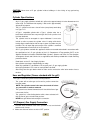
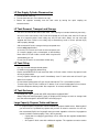
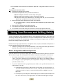
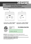
Coyote Stainless Steel Gas Grill
Use & Care Manual
For Liquid Propane and Natural Gas Models
Built-in Models
Coyote 2-Burner Grill (CC2LP/CC2NG)
Coyote 36"Grill (CS36LP/CS36NG)
Coyote 36" Grill (CSL36LP/CSL36NG)
Coyote 3-Burner Grill (CC3LP/CC3NG)
Coyote 42" Grill (CS42LP/CS42NG)
Coyote 42" Grill (CSL42LP/CSL42NG)
Conforms to ANSI
STD Z21.58a-2008
Certificated to CSA
STD 1.6a-2008
For Outdoor Use Only
PUT SERIES NO. LABEL HERE
4004477
IMPORTANT: Read the lighting instruction on Page 18 before first time use!
To installer or person assembling grill: Leave this manual with grill for future reference.
To consumer: Keep this manual for future reference.
COYOTE OUTDOOR LIVING, INC.
www.coyoteoutdoor.com
Welcome & Congratulations
Congratulations on your purchase of a new grill! We are very proud of our product and we
are completely committed to providing you with the best service possible. Your satisfaction
is our #1 priority.
Please read this manual carefully to understand all the instructions about how to install,
operate and maintain for optimum performance and longevity.
We know you’ll enjoy your new grill and thank you for choosing our product. We hope you
consider us for future purchases.
Please read and save the instructions
This Manual provides specific operating instructions for your model. Use your grill only as
instructed in this manual. These instructions are not meant to cover every possible
condition and situation that may occur. Common sense and caution must be practiced
when installing, operating and maintaining any appliance.
Table of Contents
Safety Instructions…..................... 2
Grill Models..................................4
Locating the Grill .........................5
Gas Requirements ......................7
Using Your Burners & Grilling……13
Lighting Your Grill…………………18
Operation and Features………….20
Care & Maintenance……………...21
Troubleshooting Your Grill………24
Limited Warranty……………….…26
Parts Listings……………………..28
• WARNING
IF YOU SMELL GAS:
1. Shut off gas to the appliance.
2. Extinguish any open flame.
3. Open Lid.
4. If odor continues, keep away from the
appliance and immediately call your gas
supplier or your fire department.
Safety Symbols
• WARNING
• WARNING
DANGER indicates an imminently
hazardous situation which, if not
avoided, will result in death or serious
injury.
WARNING:
1. DO NOT store or use gasoline or other
flammable liquids or vapors in the vicinity of
this or any other appliance.
2. An LP cylinder not connected for use shall
not be stored in the vicinity of this or any
other appliance.
• CAUTION
CAUTION indicates a potentially
hazardous situation which, if not
avoided, may result in minor or
moderate personal injury, or property
damage.
• WARNING
WARNING indicates a potentially
hazardous situation which, if not
avoided, could result in death or
serious injury.
• WARNING
FOR OUTDOOR USE ONLY:
NEVER operate grill in enclosed areas, as
this could lead to gas accumulating from a
leak, causing an explosion or a carbon
monoxide buildup which could result in injury
or death. DO NOT use your grill in garages,
breezeways, sheds or any enclosed area.
NOT FOR USE BY CHILDREN. If these
instructions are ignored, a hazardous fire or
explosion could result in physical injury,
death or property damage!
1
Safety Instructions
WARNING: Improper installation, adjustment, alteration, service or maintenance can cause injury
or property damage. Read the installation, operating and maintenance instructions thoroughly
before installing or servicing this equipment.
General Safety Instructions
1.
2.
3.
4.
5.
6.
7.
8.
9.
10.
11.
12.
13.
14.
15.
16.
17.
18.
For Household Outdoor Use Only – DO NOT use indoors or in any type of enclosed area such as a
garage, shed or breezeway. Keep clear of trees and shrubs. The grills are not intended for
installation in or on recreational vehicles, portable trailers, boats or any other moving installation.
Not for commercial use.
The area surrounding your new grill should be kept clean and free from flammable liquids and
other combustible materials such as mops, rags or brooms, as well as solvents, cleaning fluids,
and gasoline.
To reduce the risk of serious or fatal injury from breathing toxic fumes and from explosion and fire
as a result of leaking gas, use only outdoors in an open area with good ventilation. Do not obstruct
the flow of combustion and ventilation air.
Never use the grill in windy conditions. If located in a consistently windy area (oceanfront,
mountaintop, etc.) a wind break will be required. Always adhere to the specified clearances listed.
Do not leave the grill unattended while cooking.
Do not use natural gas in a unit designed for liquid propane gas or vice versa.
Do not use fuel such as charcoal briquettes in a gas grill.
Keep children and pets away from hot grill. DO NOT allow children to use or play near the grill.
Never attempt to repair or replace any part of the grill yourself unless specifically recommended in
this manual. All other services should be performed by a qualified service technician.
Never lean over an open grill. Do not place clothing or other flammable material on or near the grill.
Do not wear loose-fitting clothes or long sleeves while using the grill as some fabrics can be highly
flammable.
Have an ABC fire extinguisher accessible. Never attempt to extinguish a grease fire with water or
other liquids.
Never use aluminum foil to line the grill racks or the drip trays, this can alter airflow for proper
combustion and also build up heat in the control area causing the knobs and igniter to melt.
When using the grill, do not touch the grill rack, burner grate, or immediate surroundings as these
areas become extremely hot and can cause burns. Always use a covered hand when opening the
grill hood and only do so slowly to allow heat and steam to escape.
DO NOT allow grease or other hot material dripping from the grill onto valve, hose or regulator,
turn off gas supply immediately. After the grill has cooled, determine the cause and correct it. After
cleaning the valve, hose and regulator, perform a leak test before continuing use.
Do not heat any unopened glass or metal container of food on the grill. Pressure may build up and
cause the container to burst, possibly resulting in serious personal injury or damage to the grill.
Keep any electrical supply cords away from water or heated surfaces. Electrical cords should be
placed away from walkways to avoid tripping hazard.
Keep gas supply lines as short as possible.
Never move the grill when hot.
2
19. DO NOT use while under the influence of drugs or alcohol.
20. DO NOT store a spare gas cylinder under or near your grill.
21. DO NOT grill without the drip tray in place, hot grease could leak downward and produce a fire or
an explosion. Drip tray should be pushed all the way to the rack located just under the grill.
22. Grease is extremely flammable. Let hot grease cool down before attempting to handle or dispose
of it. The drip tray should be cleaned and free of grease on a regular basis.
23. In the event that a burner goes out, turn burner knobs to the full OFF position, fully open the grill
hood and let it air out. Do not attempt to use the grill until the gas has had time to dissipate.
24. Do not use grill until leak check has been made.
25. Turn off the cylinder valve when your grill is not in use.
26. Ensure the control knobs are in the “OFF” position when not in use.
27. Use only a Ground Fault Interrupter (GFI) protected circuit with this outdoor cooking gas appliance.
CALIFORNIA PROPOSITION 65 - WARNING: The burning of gas cooking fuels generates some
byproducts which are on the list of substances which are known by the State of California to cause
cancer or reproductive harm. California law requires businesses to warn customers of potential
exposure to such substances. To minimize exposure to these substances, always operate this unit
according to the Use and Care Manual, ensuring you provide good ventilation when cooking with gas.
3
Grill Models
Whether you are in need of a slimmer 2 Burner grill for your patio, or are in need of a larger 42” grill,
that can entertain and bring style to any size party, Coyote has the grill for you!
Coyote 2-Burner Grill (CC2LP/CC2NG)
Coyote 3-Burner Grill (CC3LP/CC3NG)
Coyote 36” Grill (CS36LP/CS36-NG)
Coyote 36" Grill (CSL36LP/CSL36NG)
Coyote 42” Grill (CS42LP/CS42NG)
Coyote 42" Grill (CSL42LP/CSL42NG)
Model No.
Product Size
(inch/mm)
BTU/HR
(Main/Back)
Burner(s)
Rotisserie
Motor
Hood
Light
CC2LP / CC2NG
28 (711.2)
20,000/None
2 SUS burners
No
No
CC3LP / CC3NG
34 (863.6)
60,000/None
3 SUS burners
No
Yes
CS36LP/CS36NG
CSL36LP/CSL36NG
35½ (902)
80,000/15,000
3 SUS burners, 1 sear
and 1 back burner
Yes
Yes
CS42LP/CS42NG
CSL42LP/CSL42NG
42(106.7)
100,000/15,000
4 SUS burners, 1 sear
and 1 back burner
Yes
Yes
4
Locating the Grill
Check your local building codes for the proper method of installation. In the absence of local codes, this
unit should be installed in accordance with the National Fuel Gas Code No. Z223.1-1998 USA or
CAN/CGA-B149.1/.2 Natural Gas/Propane Code (Canada) latest edition or the National Electrical
Code ANSI/NFPA No. 70 or the Canadian Electrical Code CSA C22.1, 1990 or latest version.
-
Before installing built-in grills in enclosures, copy all product information such as model number,
serial number and type of grill (e.g. natural gas or LP) and store information in a safe place.
If the grill is installed by a professional installer or technician, be sure that he shows you where
your gas supply shut-off is located. All gas lines must have a shut-off that is readily and easily
accessible. If you smell gas, check for gas leaks immediately. Check only with a soap and water
solution. Never check for gas leaks with an open flame.
Notice: We strongly recommend professional installation and hookup of the Gas BBQ grill. These
instructions will provide you with the measurements necessary for you or your builder to construct a
masonry structure to house your outdoor gas grill.
IMPORTANT: Gas fittings, regulator, and installer supplied shut-off valves must be easily accessible.
LOCATION OF YOUR GRILL:
Locate the grill only in a well ventilated area. Never locate the grill in a building, garage, breezeway,
shed or other such enclosed areas without an approved ventilation system. During heavy use, the grill
will produce a lot of smoke. Ensure there is adequate area for it to dissipate.
Wind and your Grill:
Wind is a huge factor on a gas grill’s performance. If the grill is located in a windy location (hillside,
oceanside, patio with constant breeze, etc) then a wind break will be required for proper combustion
and cooking to occur.
o If your only option is to have the grill in a windy location, build a back splash on your
island at least 6” tall to assist in wind diversion.
This will not “guarantee” proper combustion but it will assist in diverting the wind
from the grill.
o If you have a cart model and are facing a wind problem, point the back with the direction of
the wind, so that the gas still flows out of the valves and into the burners.
Clearance:
-
TO NON-COMBUSTIBLE CONSTRUCTION: For non-combustible material, Coyote grills can be
placed directly on, or adjacent to the non-combustible material. The hood on a Coyote grill pivots
mainly on the body. If you have a wall or partition behind the unit that would block ventilation, then
a minimum of 7" clearance from the back of the grill to the wall is needed for the purpose of
ventilation. If you do not have a wall or partition blocking the ventilation of the unit, then you only
need an extra 2" behind the unit for the hood to open fully. If you wish to use the rotisserie option,
you will want to make sure that you leave adequate space (at least 6") on each side of the grill so
that the motor and rotisserie spit handle will have room on the counter, as these extend past the
overall dimensions of the grill body.
5
-
-
CLEARANCE TO COMBUSTIBLE CONSTRUCTION: For combustible construction, you must
have at least 24" clearance to any combustible material (in any direction) for a Coyote Warranty to
be upheld and for the safety of the homeowner. You can NOT locate the grill under any
combustible material without an approved ventilation system directly located above the unit.
INSULATED JACKETS AND COMBUSTIBLE CONSTRUCTION: If you must use combustible
material to build your grill island AND you are going to be within 24" of the grill with this
combustible material, then you must use the appropriate Coyote Insulated Jacket. The insulated
jacket will act as a barrier to protect your grill island from the heat and fire of your Coyote grill. If an
insulated jacket is not used in a combustible material island, the warranty on the Coyote grill will be
voided immediately and safety can not be ensured.
For Built-in Installations
A built-in grill is designed for easy installation into masonry enclosures. For non-combustible
applications, the grill drops into the opening (as shown in cut-out detail drawing - Fig. A) and hangs
from the grill body itself. A bottom deck is not required to support the grill from the bottom. It is also
required that:
•
Two ventilation holes, of at least 20 sq inches in size, must be present to help release any gas
from a leak.
As Propane is heavier than air, locate your vents at the tank valve height or lower
•
The counter should be flat and level in reference to the floor.
LP TANK STORAGE MUST BE ISOLATED IN A SEPARATE COMPARTMENT FROM THAT OF THE
GRILL AND IT MUST BE VENTED AS WELL. (RECOMMEND BOTTOM VENTS FOR LP)
Cut out Dimensions Figure A
WIDTH
DEPTH
HEIGHT
6
WIDTH
DEPTH
HEIGHT
2 Burner
31” (787mm)
20 ½” (521mm)
11” (279mm)
3 Burner
32 ½” (825mm)
20 ½” (521mm)
11” (279mm)
4 Burner
39 ½” (1003mm)
20 ½” (521mm)
11” (279mm)
5 Burner
25” (635MM)
20 ½” (521mm)
11” (279mm)
Gas Requirements
NOTE: Always have a qualified service technician perform difficult conversions
or modifications.
WARNING: Never attach an unregulated gas line to the appliance. Connection to an
unregulated gas line can cause excessive heat or fire.
IMPORTANT:
Before connecting grill to gas source, make sure BBQ Grill control knobs are in the
“OFF” position.
•
Verify the type of gas supply to be used, either natural or LP, and make sure the marking on the
appliance rating label agrees with that of the supply.
•
All pipe sealants must be an approved type and resistant to the actions of LP gas. Never use
pipe sealant on flare fittings.
•
The installation of this appliance must conform with local codes or, in the absence of local
codes, with either National Fuel Gas Code, ANSI Z223.1/ NFPA 54, Natural Gas and Propane
Installation Code, CSA B149.1, or Propane Storage and Handling Code, B149.2, or the
Standard for Recreational Vehicles, ANSI A 119.2/ NFPA 1192M, and CSA Z240 RV Series,
Recreational Vehicle Code, as applicable.
WARNING: Gas valves are preset at the factory to operate on LP or natural gas. If you wish to
convert, be sure to contact your grill dealer FIRST!
LP Gas Hook-up
This propane gas grill is designed to operate on propane gas ONLY, at a pressure regulated at 11”
(279.4mm) water column (W.C.) when equipped with the correct propane orifices on the valves and a
propane regulator on the supply line regulated at the residential meter. The LP gas grill is designed to
be used with a standard 20 lbs gas cylinder and must be constructed and marked in accordance with
specifications of the US Department of Transportation for propane gas cylinders.
Always keep cylinder securely fastened in an upright position. Never connect an unregulated propane
gas cylinder to the grill.
Do not subject propane cylinders to excessive heat.
7
CAUTION: Never store a LP gas cylinder inside a building or in the vicinity of any gas-burning
appliance.
Cylinder Specifications
-
-
-
-
-
Any L.P. gas supply cylinder used with this grill must be approximately 12 inches diameter and 18
inches high. The maximum fuel capacity is 80% and is approximately
20 pounds of propane.
The L.P. cylinder must have a shut-off valve (see picture) terminating
in a Type 1 L.P.
A Type 1 compatible cylinder with a Type 1 cylinder valve has a
back-check valve which does not permit gas flow, until a positive seal
has been obtained.
The cylinder must be arranged for vapor withdrawal. It must also
include a collar to protect the cylinder valve. A safety relief device
having direct communication with the vapor space of cylinder must be
provided. This will expel high pressure gas if the cylinder is overfilled
or overheated which could result in fire or explosion.
All L.P. gas cylinders used with this appliance shall be constructed and marked in accordance with
the specifications for L.P. gas cylinders of the U. S. Department of Transportation (DOT) or the
National Standard of Canada, CAN/CSA-B339, Cylinders, Spheres and Tubes for Transportation
of Dangerous Goods; and Commission, as applicable; and shall be provided with a listed overfilling
prevention device.
Read labels on the L.P. Gas Supply Cylinder.
New cylinders are always shipped empty for safety.
Allow only qualified L.P. gas dealers to fill or repair your L.P. gas supply cylinder.
Inform the gas dealer if it is a new or used cylinder to be filled.
After filling, have the gas dealer check for leaks and to see that the relief valve remains free to
function.
Hose and Regulator (Comes standard with the grill)
The Type 1 connection system has the following features:
The system will not allow gas to flow until a positive connection
has been made.
NOTE: The cylinder control valve must be turned off before
any connection is made or removed.
The system has a thermal element that will shut off the flow of gas
in the event of a fire.
The system has a flow limiting device which, when activated, will
limit the flow of gas to 10 cubic feet per hour.
NEVER use grill without leak testing this connection.
LP (Propane) Gas Supply Connection
1. The tank valve should be in the “OFF” position. If not, turn the knob
clockwise until it stops.
2. Make sure all burner valves are in the “OFF” position.
8
3. Always connect the gas supply regulator as follows:
Insert the regulator inlet into the tank valve and turn the coupling nut clockwise until the coupler
tightens up (see picture). Do not over tighten the coupler. Turn the main tank valve on and turn the
burner control valves on the unit to the “HIGH” position for about 20 seconds to allow the air in the
system to purge before attempting to light the burners.
Pre-Operation Leak Testing
DANGER
1.
2.
3.
Do not insert any tool into the valve outlet or safety relief valve. You may damage the valve and
cause a leak. Leaking propane may result in explosion, fire, severe personal injury, or death.
If a leak is detected at any time or you cannot stop a gas leak, immediately close pipeline valve
and call LP gas supplier or you fire department!
Check all gas supply fittings before each use and each time the gas supply cylinder is connected
to the regulator. Have a qualified service technician leak test the grill any time a part of the gas
system is replaced.
WARNING
Never attempt to attach this grill to the self-contained LP gas system. Do not use grill until leak testing.
Before Testing
DO NOT smoke while leak testing. Extinguish all open flames. Never leak test with an open flame. Mix
a solution of equal parts mild detergent or liquid soap and water.
Leak Testing Valves, Hose and Regulator
1. Turn all grill control knobs to OFF.
2. Be sure hose is tightly connected to LP tank.
3. Completely open LP tank valve by turning cylinder
valve knob counterclockwise (right to left). If you hear
a rushing sound, turn gas off immediately. There is a
major leak at the connection. Correct before
proceeding by calling franchiser for replacement
parts.
4. Brush soapy solution onto areas where bubbles
are shown in LP tank (see picture).
5. If “growing” bubbles appear, there is a leak. Close
LP tank valve immediately and retighten connections.
If leads cannot be stopped do not try to repair. Call franchiser for replacement.
6. Always close LP tank valve after performing leak test by turning cylinder valve knob clockwise.
NOTE: When leak testing this appliance, make sure to test and tighten all loose connections, including
the side burner. A slight leak in the system can result in a low flame, or a hazardous condition.
9
LP Gas Supply Cylinder Disconnection
1. Turn the burner valves off.
2. Turn the tank valve off. (Turn clockwise to stop).
3. Detach the regulator assembly from the tank valve by turning the quick coupling nut
counterclockwise.
LP Tank Removal, Transport and Storage
-
-
-
Turn OFF all control knobs and LP tank valve. Turn coupling nut counterclockwise by hand only do not use tools to disconnect. Lift LP tank wire upward off of LP tank collar, then lift LP tank up
and off of support bracket. Install safety cap onto LP tank valve. Always use cap and strap
supplied with valve. Failure to use safety cap as directed may result in serious personal injury
and/or property damage.
A disconnected LP tank in storage or being transported must
have a safety cap installed
(as shown). Do not store an LP tank in enclosed spaces such
as a carport, garage, porch, covered patio or other building.
Never leave a LP tank inside a vehicle which may become
overheated by the sun.
Do not store LP tank in an area where children play.
LP Tank Filling
-
Use only licensed and experienced dealers.
LP dealer must purged tank before filling.
Dealer should NEVER fill LP tank more than 80% of LP tank volume. Volume of propane in tank
will vary by temperature.
A frosty regulator indicates gas overfill. Immediately close LP tank valve and call local LP gas
dealer for assistance.
Do not release liquid propane (LP) gas into the atmosphere. This is a hazardous practice.
To remove gas from LP tank, contact an LP dealer or call a local fire department for assistance.
Check the telephone directory under “Gas companies” for nearest certified LP dealers.
LP Tank Exchange
-
Exchange your Type 1 cylinder with OPD safety feature-equipped ONLY.
Always keep new and exchanged LP tanks in upright position during use, transit or storage. Leak
test new and exchanged LP tanks BEFORE connecting to grill.
Large Capacity Propane Tanks and Homes:
•
LP (Liquid Propane) Coyote Grills can be installed into propane fueled houses. Meaning that if
your entire house is plumbed for propane and you have an exterior connection for such use,
then a standard LP grill from Coyote will meet your needs, regardless of the size. Any appliance
can be installed if installed properly! That is the Coyote way!
o Coyote does not supply any gas fittings or lines, other than the regulator needed within
the grill box
o All Coyote LP Grills come with a 20lb tank regulator. This regulator can not be used or
10
o
modified to work on any other setup.
If you are running off of a large capacity tank (more than 20lbs), then an “in-line”
LP regulator is needed, Coyote Customer Service must be contacted to assist
with this situation.
As counties vary from state to state, it is upon the owner/installer to ensure that all
county, state and federal codes are followed for any gas installation.
- Natural Gas Hook-up
Always check the rating plate to make sure the gas supply you are hooking up to is the gas type the grill
is manufactured for.
This natural gas grill is designed to operate on natural gas ONLY, at a pressure regulated at 4”
(101.6mm) water column (W.C.) when equipped with the correct natural gas orifices on the valves and
a natural gas regulator on the supply line regulated at the residential meter.
IMPORTANT: Never connect the grill to an unregulated gas supply.
Natural gas connections must be performed by a licensed contractor or local gas company
representative.
Natural Gas Hose and Regulator
IMPORTANT: NEVER use grill without leak testing this connection.
Natural gas regulator model: GR120
Gas pressure: 4” (101.6mm)
Maximum rate working pressure: 1/2 Psig
Natural Gas Supply and Connection
1. Make sure all burner valves are in the “OFF” position
2. All NG units need to have a regulator and shut-off valve on the supply line.
3. All Pipe threads need to have proper, gas rated, outdoor rated thread sealant. Flare ends do not
need or utilize pipe sealant.
4. Your NG Coyote grill comes with a ½” regulator, along with a 18” black hose.
a) You need to seal the regulator to the hose using your pipe sealant.
b) Then attach the flare end to your manifold line, with no pipe sealant.
c) Next, attach your next connection hose (not included) to the other side of the NG regulator (it
11
is also ½” MIP)
We suggest using ½” stainless steel corrugated hoses for all NG Grills
Make sure that you purchase a hose of adequate length and capacity for the intended
application.
d) Connect the other end of this hose, to your shut off valve
i.
Depending on your choice of hose and shut-off, the nipple going into the shut-off valve
may vary.
e) Test all connections for leaks with a soap and water solution.
i.
ii.
High Elevation Installation and Use
Coyote Grills are designed to operate most efficiently at 0-2000 feet above sea level. From 2000-4000 feet
above sea level you will not notice any substantial decrease in your heat, although more gas is combusting
within the burners due to less oxygen. Above 4000 feet, you may experience a little longer cooking time on
your grill than you would experience at sea level. But again, this is just due to the air/fuel mixture taking
place within the burners. If any problems or concerns exist about your location or elevation, please contact
Coyote Customer Service for assistance.
Gas Conversions – Natural Gas and Propane
Coyote grills are able to be converted but you must obtain the correct conversion kit and we alwayrs
recommend that any gas appliance conversion should always be performed by a Licensed Plumber or a
certified Installer. Conversion kits are sold for Coyote grills and can be purchased through your dealer, or
Coyote’s Customer Service Department. Any other kit or orifices used that are not of Coyote brand, will
automatically void any warranty on the unit. Furthermore, it is important to understand that where ever there
is a burner, there is an orifice that will need to be changed (do not forget the rotisserie or sear burner).
The steps for converting your Coyote grills main and sear burners are:
1. Pull grill out of island or cart.
2. Remove Drip Pan and Cooking Grates
3. Unscrew bolt connecting the manifold pipe to the grill body, located at the back side of the grill.
4. Unscrew the 4 bolts holding the faceplate to the body (on the front edge where your cooking grate
sits)
5. Unscrew the 2 bolts (on each side) of the manifold and faceplate assembly, that holds this entire
assembly to the body of the grill.
6. Disconnect all wires and flex lines, from the valves and igniter assembly while paying close
attention to their original location.
7. Slide entire control panel and valve assembly out from the grill body.
8. Flip control panel over on its side, so you have easy access to the valves.
9. Sear Burner Grills Only – Remove center knob, unscrew top and bottom screws only.
a. The safety valve that controls the thermocouple on your sear burner must be completely
changed. You cannot change only the orifice.
10. Sear Burner Grills Only – Unscrew base bracket, hold center valve to gas manifold pipe and
remove valve
11. Sear Burner Grills Only – Install new Safety Valve in the correct gas type and follow the removal
instructions in reverse.
12. Once the panel is flipped over, you will see the orifice at the end of the valve. With a wrench remove
the orifice from the valve and install the new gas orifice,
12
13. Re-assemble in reverse and test all connections again with a soapy water solution to ensure no
leaks.
To convert your rear burner orifice:
1. Remove your entire rotisserie assembly
2. Remove the back panel that covers your rear rotisserie burner
a. With the hood open, remove the 4 screws on top of this panel
b. With the hood closed, remove the 4 screws on the back of this panel
c. With the hood closed, look underneath this same back panel and you will see 4-5 bolts
(depending on your grill), these only need to be loosened
3. Next, pull the entire panel (starting from the back) out from the grill
a. It is designed to fit tight, so you may need a flat head screwdriver to pop the stainless away
from the body
4. Next, you will see the gas line, brass elbow and orifice
5. Use a wrench to remove the orifice and install the new one
6. Re-assemble in reverse and check your back burner to ensure proper ignition and burning
Using Your Burners and Grilling Safely
Your grill is designed to reach a temperature that you set by adjusting a valve that in turns adjusts the
amount of gas that goes through each burner. This Valve is located behind your knob and is the key to your
heat and fuel consumption. An example being: Cooking on low will give you longer use out of a 20lb LP
tank than will cooking on high every single time.
Furthermore, the way to ignite the burners is through the valves, so please understand the importance of
this piece and the position/care taken to the knobs.
•
Example: If you forget to turn a knob off and the burner is not lit, then you will have a gas leak out of
that valve. You must be aware of your grills status and be responsible!
Burner Configuration and Heat Dispersion:
If you look under the very front of your cooking grates, you will realize that for the first few inches, the burner
does not release any gas. This is designed to be the medium heat portion of your grill for several reasons.
•
One being that the flavorizers ensure even heat dispersion laterally across your grills cooking
surface, so the front is designed to be your medium heat section, while you can utilize the middle of
your cooking grates to get a good high heat (do not forget that this all depends on how high you have
your valves turned as well).
•
As you move towards the back of your grill and past the middle section, you will realize that this is the
hottest portion of your grill.
o
Underneath, where the burner is bolted to the back of the body, you will see that there is a
“crossover” in between each burner. This crossover, sends gas from one burner to the next
(as long as the valves are open), to ensure that all of your burners will light in case your
igniters fail.
o
For example, if you can only get one burner to light, you just need to keep the hood open and
turn on the valve next to it, to the high position. Gas will then travel through the new/open
13
burner and will catch the flame from the initial burner. This crossover does provide you
constant heat across the back that increases the temperature and provides you with your
hottest position on the grill (unless you have a CS model with a sear burner – in which the
sear burner will provide your highest temperature for cooking/searing).
To understand how this will effect your cooking, please take a look at the pictures below for visual assistance.
Burner Use – Indirect, Direct, Sear, Rotisserie Cooking
As you can imagine, by controlling how much gas flows through your burner; determines the size of your
flame. The ideal flame will be blue, with no yellow tip, or excessive noise coming out of the burner.
If you happen to have any of these problems:
•
You will want to check the air adjustment screw on the side of the burner itself (called the Air
Venturi) and also the adjustment screw that resides directly below the orifice to ensure proper gas
flow into the burner from the valve
•
There are many reasons that can cause poor flames and heat but none are more serious than a
gas leak, so always pay attention for the odor of gas (NG or LP) but do not also forget to clean your
burners!
For Direct Cooking you simply cook your food over a direct flame that is hot and quick to cook but is also
the quickest way to burn your food. Pay attention closely if you choose this method!
Indirect Cooking however is used for larger cuts of meats and anything that you are intending to keep nice
and juicy!
•
All you need to do is turn off the burner that lies under the food being cooked and adjust the exterior
burners flame so that you create a slow, constant and even cooking environment for your food!
14
If you are looking for a cooking experience that will almost instantly cook your food item, then Sear
Cooking is an essential! Sear Cooking uses a ceramic burner that emits a different form of heat that can
produce a much higher temperature quicker, to lock in the juices!
Now, if you are looking for an experience that will allow you to have a juicy bird, straight from the rotisserie
of your grill, then Rotisserie Cooking is going to be your choice! Coyote grills utilize the same ceramic
burner technology in their sear burner, as their rotisserie burner, along with a motor and spit that will hold
and rotate up to 20lbs of food. Allowing you to cook a bird amazingly quick, without burning or charring any
portion of it
Instruction for Rotisserie Assembly
WARNING: Never stand with your head directly over the Grill when preparing to light the Rotisserie
burner, to prevent possible bodily injury.
Rotisserie is mostly used to cook large pieces of meat and poultry to assure slow, even cooking. The
constant turning provides a self-basting action, making food cooked on a rotisserie exceptionally moist
and juicy. Rotisserie cooking generally requires 1 ½ to 4½ hrs to cook depending on the size and type
of meat being cooked. You can have rotisserie cooking with indirect heat with infrared rotisserie burner.
Preferred by professional chefs over other methods, the intense heat is ideal for searing in the natural
juices and nutrients found in quality meats.
For successful rotisserie, the meat should be centered and balanced as evenly as possible on the spit
rod to avoid overworking the rotisserie motor.
1.
Attach Motor Bracket Assembly to the side of the barbecue frame (can be mounted on
either left or the right side of the frame) using two screws and two nuts.
2.
Insert Rotisserie Motor onto Motor Bracket Assembly.
3.
Assemble Key Washer, Counter-balance and handle to Spit Rod. Slide Shaft Collar with long end
towards handle.
4.
Slide Prong Forks with the prongs facing away from the handle onto the Spit Rod. Place food on
to Spit Rod and secure with the second Prong Forks. Secure with thumbscrews. Place Spit Rod
assembly and position into Motor. Secure position with thumbscrew. It may be necessary to
secure any loose portions with butcher's string. Never use nylon or plastic string as it will melt
and ruin the food.
5.
Once the food is secured, place the sharp end of the Spit Rod onto the motor, and then rest
the Spit Rod on the supports at either side of the grill.
6.
Ensure that all Bolts are tightened securely.
7.
When the rotisserie is being operated exclusively, it is strongly recommended that a pan be
placed on the grilling grids, beneath the food to catch the meat drippings. This will prevent
excessive build up of drippings on the grids and facilitate cleaning.
a)
If your food is large and a pan will not fit on top of the grates, you can remove the cooking
grates and place your pan directly on the flavorizers.
i.
The center of your spit rod to the top of the hood, equals the same distance from the
spit rod to the top of the flavorizers.
NOTE: Close hood carefully and align Motor Bracket and Shaft Mounting Bracket so that Rotisserie
Rod is in between the hood openings.
No.
Qty
Description
15
1
No.
1
2
3
4
5
6
7
8
9
1
Qty
1
1
1
2
2
1
1
2
2
110V Motor
Description
110V Motor
Motor Bracket
Spit Rod
Shaft Collar
4-Prong Fork
Handle
Counterbalance
Screw
Hexagonal Head Screw
WARNING: Never operate Rotisserie Burner with main (other) burner(s) “ON”. Warming Rack
must be removed when Rotisserie Burner is ON.
Electrical Grounding Instructions:
•
•
•
The rotisserie motor is equipped with a three-prong grounding plug for your protection against
electric shock. This plug must be inserted directly into a properly grounded three-prong
receptacle. Do not cut or remove the grounding prong from this plug.
The rotisserie motor must be electrically grounded in accordance with local codes or, in the
absence of local codes, in accordance with the National Electrical Code, ANSI/NFPA 70-1990
or Canadian Electrical Code, CSA C22.1.
Do not use an extension cord to supply power to your grill. Such use may result in fire,
electrical shock or other personal injury. Do not install a fuse in the neutral or ground circuit. A
fuse in the neutral or ground circuit may result in an electrical shock hazard. Do not ground this
appliance to a gas supply pipe or hot water pipe.
Instruction for Connecting the Transformer
1. Transformer for Interior Lights - (only on CC3 and CS models)
Your transformer will connect on the left side of your grill (looking at it from the front) and operates the
lights inside your grill. Follow the pictures and insert the white male plug into the white female socket,
on the left side of your grill and then plug the transformer into a standard 110v outlet.
Left Side of Grills
Male Plug
Female Socket
2. Transformer for Back Lit Knobs – (only on CSL36 and CSL42 models with back lit knobs)
Your transformer will connect on the left side of your grill (looking at it from the front) and operates the
LED lights behind knob bezels. Follow the pictures and connect the transformer, and then plug the
transformer into a standard 110v outlet. Read below instruction for how to change new LEDs.
16
The Left Side of Grill
Connect the Transformer
Remove the Knob
Remove the Screws
Take Down the Knob Bezel
The LED Plastic Bezel
Pull Out the Wires
Disconnect the Wire and Change New LEDs
Do the opposite to assemble the LEDs.
WARNING: These two transformer should be kept away from the heat of the BBQ.
17
Lighting the Grill
DANGER
•
Failure to open the lid while igniting the barbecue’s burners, or not waiting 5 minutes to allow
the gas to clear if the barbecue does not light, may result in an explosive flame-up which can
cause serious bodily injury or death.
WARNING
•
•
•
DO NOT use the grill if gas odor is present.
DO NOT stand with head, body, or arms over the grill when lighting.
Inspect the hose before using the grill. If there is excessive abrasion or wear, or if the hose is
cut, it must be replaced prior to the outdoor cooking gas appliance being put into operation.
The replacement hose assembly shall be that specified by the manufacturer.
•
Ensure the area around the barbecue is clear of flammable substances such as gasoline, yard
debris, wood, etc.
•
Ensure there is no blockage of the airflow through the vent space located below the face of the
unit.
GENERAL RULES
Do not leave the grill unattended while cooking!
-
Make sure the grill has been leak tested and is properly located.
Check the end of each burner tube is properly located over each valve orifice.
Light the grill burners using the instructions provided in this manual.
Adjust heat settings to your desired cooking temperature.
Allow grill to cool down, wipe off any splatters or grease and clean the drip tray as needed.
Do not put a cover on the grill while it is still hot as it could start a fire.
NOTE: If for some reason, igniters fail to light, burners can be lit with a gas lighter.
NOTE: Replace battery under ignition cap (twist off counter-clockwise)
NOTE: To light gas grill with a gas lighter, make sure the
grill has been leak tested and burners be properly located.
Remove the cooking grids and flavorizers from burner you
wish to light. Insert long-necked gas lighter placing near to
burner ports. Press in the last right control knob and rotate left
to “HIGH” setting to release gas. Turn on the button on gas
lighter, burner should light immediately. Place back the
cooking grids and flavorizers. Adjust burners to desired
cooking temperature.
Keep any electrical supply cords and the fuel supply hose away from any
heated surfaces.
18
Lighting Instructions
OPEN LID
Igniter
ENSURING BURNER CONTROLS
ARE IN “OFF” POSITION, TURN ON
Left Knob
THE GAS SUPPLY VALVE.
Back Burner
Knob
Right Knob
Be sure a AA battery is inserted inside the igniter.
Main Burner Lighting
Infrared Back Burner Lighting
1. Push and hold the igniter, then push in
and turn the last Right knob to HIGH
position 3-5 seconds to light burner.
1. Push and hold the igniter, then turn the
2. If ignition does not occur in 5 seconds,
turn the last Right control knob to “OFF”,
wait 5 minutes to allow gas to dissipate
and repeat the lighting process.
2. If ignition does not occur in 5 seconds,
turn the back burner control knob to “OFF”,
wait 5 minutes to allow gas to dissipate
and repeat the lighting process.
3. To light the other SUS burners, push
in and turn control knob one by one
counter-clockwise to HIGH position and
adjust to desired cooking temperature.
3. Adjust the back burner control knob
counterclockwise to desired cooking
temperature.
4. To light the sear burner, push and hold
the igniter, then push in and turn the Left
knob to HIGH position 3-5 seconds to
light sear burner.
19
back burner knob to HIGH position 3-5
seconds to light the back burner.
Operations and Features
When you first ignite your grill burn the grill to get rid of any odors or debris that may be left over from
manufacturing and transit. This is done by operating your grill at the “HIGH” setting with the hood
closed for no more than 5 minutes.
• Since this is a high temperature grill; closing the hood will cause heat to build up and could
easily cause an excessive flare-up that could cause internal damage to the grill (knobs, igniter,
etc.).
• After you have “burned off” the grill, you are ready for cooking!
Preparing Food for the Grill
WARNING: Always observe safe food-handling and safe food-preparation practices when using
this Grill, to prevent food-borne illnesses.
-
Always cook foods adequately. Undercooked foods can retain bacteria, especially if thawed or
exposed to warm conditions prior to cooking.
Always use separate plates and utensils for the handling of raw food. Never place raw food and
cooked food on the same plate, and never place cooked food on a plate that was used for handling
raw food.
Always carefully wash all plates and utensils used to handle raw food before using them to handle
cooked food.
Always wash all vegetables, seafood and poultry before cooking.
Always leave uncooked foods in the refrigerator until you are ready to start cooking.
Always marinate meat in the refrigerator. Dispose of the excess marinade, and never reuse it.
Grilling Tips:
If you pre-cook meat or poultry, do so immediately before grilling.
Refrigerate leftovers within 2 hours of taking food off the grill.
- Never let the tray boil dry. That could be hazardous, as grease from fatty foods that have
-
collected in the tray could ignite and possibly cause bodily injury or property damage.
Use a meat thermometer to be sure food has reached a safe internal temperature.
Always trim excess fat from your foods to reduce the occurrence of flare-ups during cooking.
Apply a light coating of cooking oil to the cooking grids before grilling, to prevent foods from
sticking.
Cook similar portion sizes together, so that they all cook evenly.
Use tongs to turn foods on the grill.
Never pierce foods while they are cooking on the Grill, as this will dry them out.
Turn foods infrequently. Some chefs say that a good steak should never be turned more than
once.
Apply sugar-based sauces such as commercial barbecue sauces only during the latter stages of
cooking, to prevent charring.
Soak the string you use to tie up roasts and poultry on the rotisserie spit to protect it from burning.
Use a disposable aluminum tray filled with water, fruit juice, wine or a marinade to add extra flavor
and moisture to slow-cooked foods like roasts, whole chickens, turkeys or ducks.
Controlling Flare-ups
Flare-ups are a part of cooking meats on a gas grill. This adds to the unique flavor of cooking on a gas
grill. Excessive flare-ups resulting from the build-up of grease in the bottom of the grill can over-cook
the food and cause a dangerous situation for you and your grill. If this should occur, DO NOT pour
water onto the flames, which can cause the grease to splatter and could result in serious burns or
bodily harm. If grease fire occurs, close the hood and turn off the main burners until the grease burns
out. Use caution when opening the hood as sudden flare-ups may occur.
20
To Minimize Flare-ups:
-
Trim excess fat from meats prior to cooking.
Cook meats with high fat contents (chicken or pork) on Low settings or indirectly.
Ensure that your grill is on level ground and the grease is allowed to evacuate the grill through the
drain hole.
Care & Maintenance
CAUTION: All cleaning and maintenance should be done only when grill is cool & with the fuel
supply turned off at the cylinder. If your grill is set up for use with Natural Gas, turn off gas supply at
the system manual shut off valve.
DRIP TRAY
The drip tray located below the grill should be cleaned periodically to prevent heavy buildup of debris.
NOTE: Allow the drip tray to cool before attempting to clean.
IMPORTANT: Do not leave the grill outside during inclement weather unless it is covered (cover sold
separately). Rain water can collect inside the grill, the grill cart or the drip tray if left uncovered. If the drip
tray is not cleaned after use and the grill is left uncovered, the drip tray will fill with water causing grease
and water to spill into the grill cart. We recommend cleaning and storing the drip tray after every use.
COOKING GRATES
The cooking grates can be cleaned immediately after cooking is completed and after turning off the grill.
Wear a barbecue mitt and scrub the cooking grates with a damp cloth. If the grill is allowed to cool down,
cleaning the grates will be easier if removed from the grill and cleaned with a mild detergent.
FLAVORIZERS
Washing the flavorizers after every use is not necessary but periodically it is suggested you wash them
in a soap and warm water solution. Use a wire brush to remove stubborn burned on cooking residue.
Dry the flavorizers & flame dividers thoroughly before you reinstall them in the cooking insert.
BURNERS
IMPORTANT: Gas control knobs should be in the “OFF” position and fuel line should be disconnected.
To reduce the chance of FLASHBACK, the procedure below should be followed at least once a month or
when your grill has not been used for an extended period of time.
Main Burners:
1. Remove your main burners from the grill by removing the nut holding the burner down in the
back and carefully lifting each burner up and away from the gas valve orifice.
2. Wire brush entire outer surface of burner to remove food debris and dirt. Clean any clogged
ports with a stiff wire such as an open paper clip.
3. Inspect the burner for damage (cracks or holes) and if such damage is found, order and install a
new burner.
21
4. After installation, check to insure that gas valve orifices are correctly placed inside ends of
burner tubes. Also check position of spark electrode.
Sear Burners: Sear burners are made out of ceramic and emit gas in a honeycomb pattern that is
almost impossible to see. However, these burners get exceptionally hot and can be exceptionally
easy to damage. The way to clean these burners is:
1. Remove all large pieces of food from the top of the burner
2. Turn the burner on high and let the temperature do the work
3. Do not leave the grill unattended while doing this as you will want to make sure no excessive
flare ups occur
4. Once all excess grease has been burned off, you are ready to go!
a. An easy way to keep your sear burner from getting dirty is to allow it to run for a few
minutes after you are done cooking, so that you do not have to re-heat your grill just
to clean.
STAINLESS STEEL
After initial usage, areas of the grill may discolor from the intense heat given off by the burners. This is
normal. Purchase a mild stainless steel cleaner and rub in the direction of the grain of the metal. Specks
of grease can gather on the surface of the stainless steel and bake on to the surface and give a worn
appearance. For removal, use a non-abrasive oven cleaner in conjunction with a stainless cleaner. If
spots are persistent, then petroleum jelly may be used to help remove the spots.
NOTE: Always scrub in the direction of the grain.
HOW TO CHANGE THE LIGHT BULBS - (CC3 and CS Models only)
1. Remove the screw holding the bulb lens.
2. Reach in using your fingers only, grip the two outside edges of the light bulb, do not grip the top
or bottom of the bulb, as it might break. Pull the bulb straight out, so that the two electrode wires
are completely removed with bulb. Place bulb in trash.
3. When installing the new halogen bulb be sure to use a clean cloth or paper towel to ensure the
longevity of the bulb.
4. Insert the new bulb using your clean cloth and gently snap it into position. Wipe off any
fingerprints and/or grease that may have transferred to the bulb.
5. Re-install the bulb lens and cover
6. Flip the switch on to check lights.
ANNUAL CLEANING OF GRILL HOUSING
Burn-off the barbecue after every cookout will keep it ready for instant use, however, once a year you
should give the entire grill a thorough cleaning to keep it in top operating condition.
1. Shut off gas supply at source and disconnects fuel line. Protect fuel line fitting.
2. Remove and clean the cooking grids, flavorizers and burners.
3. Remove warming rack and wash with mild detergent and warm water.
4. Cover the gas valve orifices with a piece of aluminum foil.
5. Brush the inside and bottom of the grill with a stiff wire brush, and wash down with a mild soap and
warm water solution. Wash thoroughly and let dry.
22
6.
7.
8.
9.
Remove aluminum foil from orifices and check orifices for obstruction.
Check electrode.
Reinstall flavorizers, cooking grids, and warming rack.
Reconnect to gas source and observe burner flame for correct operation.
IMPORTANT: You should NOT line the bottom of the grill housing with aluminum foil, sand or any
other grease absorbent substance. Grease will not be able to drip into the drip tray and a grease fire
may occur.
MAINTENANCE GUIDELINES
1. Keep outdoor cooking gas appliance area clear and free from combustible materials, gasoline
and other flammable vapors and liquids.
2. Do not obstruct the flow of combustion and ventilation air.
3. Keep the ventilation opening(s) of the cylinder enclosure free and clear from debris.
4. Visually check burner flames. Burner flames should be blue and stable with no yellow tips, excessive
noise, or lifting. If any of these conditions exist call our customer service line.
5. Clean outdoor cooking gas appliance, including special surfaces, with recommended cleaning
agents, if necessary.
6. Check and clean burner for insects and insect nests. A clogged tube can lead to a fire beneath the
grill.
Recommended Cleaners for Specific Situations
JOB
Routine Cleaning
Fingerprints & smears
Stubborn stains &
discoloration
Grease & Oil
Restoration/ Passivation
CLEANING AGENTS
Soap, ammonia, detergent
Medallion
Arcal 20, Lac-O-Nu Ecoshine
Cameo, Talc, Zud
First Impression
Any good commercial
detergent
Benefit, Super Sheen
23
COMMENTS
Apply with cloth or sponge
Provides barrier film
Rub in direction of polish lines
Apply with sponge or cloth
Troubleshooting Your Grill
GENERAL TROUBLE SHOOTING
You should inspect the burners at least once a year or immediately if any of the following conditions
occur:
• The smell of gas.
• Flames appearing mostly yellow. (Some yellow at the tips is OK)
• The grill will not get hot enough.
• Burners make a snapping noise.
• The grill heats unevenly.
SPIDER AND INSECT WARNING
:
INSECT WARNING Spiders and insects can nest in the burners of this and other grills, which could
disrupt gas flow. This dangerous condition could cause a fire behind and beneath the valve panel,
damaging the grill and making it unsafe to operate. We recommend you check the grill and remove any
spiders, insects and webs at least once a year to reduce this risk.
WHEN TO LOOK FOR SPIDERS
You should inspect the burners once a year or immediately after any of the following conditions occur:
1. The smell of gas in conjunction with the burner flames appearing yellow.
2. The grill does not reach temperature.
3. The grill heats unevenly.
4. The burners make popping noises.
BEFORE CALLING FOR SERVICE
If the grill does not function properly, use the chart below before contacting your dealer for service. You
may save yourself the cost of a service call. Troubleshooting is for general purposes only. If the problem
still exists, contact your dealer or the nearest authorized agency for service.
Problem:
Possible Causes and Solutions:
Grill will not light when the
•
Is your gas supply turned on?
igniter button is pushed.
•
If this is an L.P. grill, is there gas in your tank? Check your gas
level.
•
Is one of your burners turned on? Allow up to 5 seconds of gas
flow to ignite.
•
Is your igniter working?
- You should hear a snapping sound when you press the
igniter.
- If you hear a snapping sound, can you see a spark at the
electrodes?
24
Note: You will need to remove your cooking grates and
flavorizers to see the electrodes. The electrodes should
have a 1/8” to ¼” gap between the electrode and contact
point.
Flare-ups
•
Check your igniter battery and replace if needed.
•
Check for loose wire connections to the igniter or electrodes.
•
Check to see if debris is blocking the electrodes.
•
If the igniter is not working, can you light the grill with a lighter?
•
Check flavorizers and cooking grates for excess food or
•
Ensure grill is not placed directly in the path of wind.
grease build-up.
Be sure drip tray is clean (do not use aluminum foil on drip
tray.)
Note: Some flare-ups may be inevitable if cooking greasy
Yellow Flames
Flame blows out on low setting
or has uneven heat distribution.
Low heat with the knob on
“HIGH”
Grill is Too Hot
Flame behind control panel or
control knob area.
Fire at any connection.
foods.
•
Check the burner inlet for obstructions, particularly at air inlets
for each burner.
• Grill may be in an area that is too windy.
•
Check for spider webs or insect nest in venturi and clean
venturi.
•
Cold grill needs to be preheated for 5 minutes on high setting.
•
Venturi may be misaligned and needs to be lined up over
orifices.
•
Cold and windy weather will require you to move grill away
from the wind.
•
Lack of fuel. Check to see cylinder valve is open and cylinder
has fuel.
•
Check to see if the fuel hose is bent or kinked.
•
Make sure the grill area is clear of dust.
•
Check your gas supply and gas pressure.
•
If it is only one burner that appears low, make sure the orifice
or burner is clean.
•
Excess grease build-up causing grease fires.
•
Damaged or faulty regulator.
Replace with factory authorized parts.
• Cook on a lower temperature setting.
IMMEDIATELY shut off cylinder valve and allow grill to cool.
•
Check for spider webs or insect nest in venturi and clean
venturi.
•
Gas is leaking from a faulty connection. Tighten connections
with an adjustable wrench and replace damaged parts.
Perform a leak test on all connections before cooking on grill
again.
•
Venturi may be misaligned and needs to be lined up over
orifice.
IMMEDIATELY shut off cylinder valve and allow grill to cool.
•
Gas is leaking from a faulty connection. Tighten connections
with an adjustable wrench and replace damaged parts.
•
Perform a leak test on all connections before cooking on grill
again.
25
Limited Warranty
LIMITED WARRANTY
Coyote Outdoor warrants to the original purchaser at the original site of delivery with proof of
purchase of each Outdoor Gas grill/Side burner that when subject to normal residential use, it is
free from defects in workmanship and materials for the periods specified below. This warranty
excludes grills used in rental and commercial applications. This warranty excludes surface
corrosion, scratches, and discoloration which may occur during regular use. It does NOT cover
labor or labor related charges. There will be shipping and handling charge for the delivery of the
warranty part(s).
COMPONENT
WARRANTY PERIOD
Cooking Grids (no rust or burn through) ………………………..................................5 years (limited)
Flavorizer Bars (no rust or burn through)…………………………………....................2 years (limited
Electric/Plastic Components ………………………………………………………..........2 years (limited)
Ignition systems/Valves ……………………………………………………………….......1 year (limited)
Stainless steel frame/housing ……………………………………………………............Limited Lifetime
Stainless Steel Burners (no rust or burn through)……………………..........................Limited Lifetime
Our obligation under this warranty is limited to repair or replacement, at our option, of the
product during the warranty period. The extent of any liability of Coyote under this warranty is
limited to repair or replacement. This warranty does not cover normal wear of parts, damage
resulting from any of the following: negligent use or misuse of the product, use on improper
fuel/gas supply, use contrary to operating instructions, or alteration by any person other than a
factory service center. The warranty period is not extended by such repair or replacement.
WARRANTY CLAIM PROCEDURE: If you require service or parts for your Coyote Grill,
please contact our Warranty Service Center for factory direct assistance. Our hours of operation
are 8 am to 4 pm CST. The phone number is 855.520.1559 and the Fax number is 214.520.1450.
You may also fill out warranty claims online at www.coyoteoutdoor.com. Please have your
model number, serial number and proof of purchase available for any warranty claim.
Coyote Outdoor may require the return of defective parts for examination before issuing
replacement parts. If you are required to return defective parts, shipping charges must be prepaid
by the customer. Upon examination and to Coyote Outdoor’s determination, if the original part is
proven defective, Coyote Outdoor, may approve your claim and elect to replace such parts without
charge. In any instance, customer is responsible for shipping and handling of the replacement
parts.
Product repair as provided under this warranty is your exclusive remedy. Coyote
Outdoor shall not be liable for any incidental or consequential damages for breach of any express
or implied warranty on its products.
This warranty does not cover any failures of operating difficulties or operating difficulties due
to accidents, abuse, misuse, alteration, misapplication, vandalism, improper installation,
maintenance or service, damages caused by flashback fire or grease fires, as set out in the
26
Owner’s Manual. This warranty does not cover scratches, dents, corrosion or discoloration caused
by weather, heat, abrasive and chemical cleaners, pool or spa chemicals, and/or any tools used in
the assembly or installation of this unit. This warranty does not cover paint loss, surface rust,
corrosion or stainless steel discoloration which is considered normal wear and tear. This warranty
does not cover the cost of any inconvenience, personal injury, or property damage due to improper
use or product failure. Deterioration or damage due to severe weather conditions such as hail,
hurricanes, earthquakes, tsunamis, tornadoes, terrorism, discoloration due to exposure to
chemicals either directly or in the atmosphere, Acts of God/forces of Nature are not covered by this
limited warranty.
27
Parts List
COYOTE 2B
28
NG/LP
COYOTE 2B NG/LP PARTS LISTING
No.
Name
Description2
1
Hood
Hood -2B
1
C2B00005
2
Thermometer
Thermometer
1
C0000022
3
Handle Fixing
Handle Fixing
2
C0000007
4
Hood Handle
Hood Handle -2B
1
C2B00006
5
Rubber Stopper on Hood
Rubber Stopper on Hood
2
C0000032
6
Lower Hood
Lower Hood-2B
1
C2B00007
7
Warming Rack Bracket
Warming Rack Bracket
2
C0000025
8
Warming Rack
Warming Rack-2B
1
C2B00008
9
Grate-CC2 (1pc) 14 Bar
Grate-CC2 (1pc) 14 Bar
1
CCG00014
10
Grate-CC2 (1pc) 15 Bar
Grate-CC2 (1pc) 15 Bar
1
CCG00015
11
Flavorizer
Flavorizer-2B
2
C2B00009
12
SUS Burner
SUS Burner - 201
2
C0000201
13
Electrode Length = 230mm
Electrode Length = 230mm
1
C0000230
14
Gas Pipe
Gas Pipe-2B
1
C2B00010
15
Standard Valve (SUS Burner) NG
Standard Valve (SUS Burner) NG
2
C0000036
15
Standard Valve (SUS Burner) LP
Standard Valve (SUS Burner) LP
2
C0000037
16
Firebox
Firebox-2B
1
C2B00003
17
Drip Tray
Drip Tray-2B
1
C2B00002
18
Igniter
Igniter
1
C1P00008
19
Control Panel
Control Panel-2B
1
C2B00001
20
Knob Base
Knob Base
2
C0000012
21
Knob
Knob
2
C0000011
22
LP Regulator
LP Regulator
1
C0000030
23
NG Regulator
NG Regulator
1
C0000038
29
Qty
Part No.
COYOTE 3B
30
NG/LP
COYOTE 3B NG/LP PARTS LISTING
No.
Name
Qty
1
Hood
Hood -3B
1
C3B00005
2
Thermometer
Thermometer
1
C0000022
3
Handle Fixing
Handle Fixing
2
C0000007
4
Hood Handle
Hood Handle -3B
1
C3B00006
5
Rubber Stopper on Hood
Rubber Stopper on Hood
2
C0000032
6
Light
Light Bulb
2
C0000014
7
Warming Rack Bracket
Warming Rack Bracket
2
C0000025
8
Warming Rack
Warming Rack-3B
1
C3B00008
9
Grate-CC3 (1pc) 18 Bar
Grate-CC3 (1pc) 18 Bar
1
CCG00018
10
Grate-CC3 (1pc) 19 Bar
Grate-CC3 (1pc) 19 Bar
1
CCG00019
11
Flavorizer
Flavorizer-3B
3
C3B00009
12
SUS Burner
SUS Burner - 201
3
C0000201
13
Electrode Length = 230mm
Electrode Length = 230mm
1
C0000230
14
Gas Pipe
Gas Pipe-3B
1
C3B00010
15
Standard Valve (SUS Burner) NG
Standard Valve (SUS Burner) NG
3
C0000036
15
Standard Valve (SUS Burner) LP
Standard Valve (SUS Burner) LP
3
C0000037
16
Lower Hood
Lower Hood-3B
1
C3B00007
17
Firebox
Firebox-3B
1
C3B00003
18
Drip Tray
Drip Tray-3B
1
C3B00002
19
3 Burner Light Wire
3 Burner Light Wire
1
C3000001
20
Transformer
Transformer
1
C0000023
21
Waterproof Switch
Waterproof Switch
1
C3642017
22
Control Panel
Control Panel-3B
1
C3B00001
23
Igniter
Igniter
1
C1P00008
24
Knob Base
Knob Base
3
C0000012
25
Knob
Knob
3
C0000011
26
LP Regulator
LP Regulator
1
C0000030
27
NG Regulator
NG Regulator
1
C0000038
31
Part No.
COYOTE 4B w/ Sear Burner & IR NG/LP
32
COYOTE 4B w/ Sear Burner & IR NG/LP PARTS LISTING
No. Name
1 Hood
Hood -36
2 Thermometer
Thermometer
3 Handle Fixing
Handle Fixing
4 Hood Handle
Hood Handle-36
5 Rubber Stopper on Hood
Rubber Stopper on Hood
6 Warming Rack Bracket
Warming Rack Bracket
7 Warming Rack
Warming Rack-36
8 Rotisserie Kit
Rotisserie Kit - 36
9 Light
Light
10 Electrode Length = 950mm
Electrode Length = 950mm
11 Thermocouple = 1350mm
Thermocouple
12 IR Lighting Box
IR Lighting Box
13 Rotisserie Rod Bracket
Rotisserie Rod Bracket
14 IR Burner-36
IR Burner-36
15 Lower Hood
Lower Hood-36
16 Motor
Motor
17 Motor Bracket
Motor Bracket
18 Stainless Steel Corrugated Hose
Stainless Steel Corrugated Hose 1250mm
19 4 Burner Light Wire
4 Burner Light Wire
20 Firebox
Firebox-36
21 Drip Tray
Drip Tray-36
22 Grate-CS36 (1pc) 19 Bar
Grate-CS36 (1pc) 19 Bar
23 Grate-CS36 (1pc) 20 Bar
Grate-CS36 (1pc) 20 Bar
24 Smoker Box
Smoker Box
25 Flavorizer
Flavorizer-36
26 Transformer
Transformer
27 SUS Burner
SUS Burner - 304
28 Sear Burner
Sear Burner
29 Control Panel
Control Panel-36
30 Igniter
Igniter
31 Knob Base
Knob Base
32 Knob
Knob
33 Waterproof Switch
Waterproof Switch
34 Gas Pipe
Gas Pipe-36
35 Electrode Length = 230mm
Electrode Length = 230mm
36 Standard Valve (SUS Burner) NG
Standard Valve (SUS Burner) NG
36 Standard Valve (SUS Burner) LP
Standard Valve (SUS Burner) LP
37 Safety Valve (IR Burner) NG
Safety Valve (IR Burner) NG
37 Safety Valve (IR Burner) LP
Safety Valve (IR Burner) LP
38 Sear Burner Valve NG
Sear Burner Valve NG
38 Sear Burner Valve LP
Sear Burner Valve LP
39 Electrode Length = 800mm
Electrode Length = 800mm
40 LP Regulator
LP Regulator
41 NG Regulator
NG Regulator
42 LED Transformer
LED Transformer
43 LED Light Ring
LED Light Ring
44 LED Wiring Harness
LED Wiring Harness
33
Qty
1
1
2
1
2
2
1
1
2
1
1
1
2
1
1
1
1
1
1
1
1
1
1
1
3
1
3
1
1
1
5
5
1
1
1
3
3
1
1
1
1
1
1
1
1
1
1
Part No.
C3600005
C0000022
C0000007
C3600006
C0000032
C0000025
C3600008
CROT0036
C0000014
C0000950
C3600018
C0000010
C0000018
C3600011
C3600007
C0000015
C0000016
C0000031
C4000001
C3600003
C3600002
CCG00019
CCG00020
C0000020
C3600009
C0000023
C0000304
C0000019
C3600001
C3P00008
C0000012
C0000011
C3642017
C3600010
C0000230
C0000036
C0000037
C3642011
C3642012
C3642015
C3642016
C0000800
C0000030
C0000038
C0000040
C0000041
C0000042
COYOTE 5B w/ Sear Burner & IR NG/LP
34
COYOTE 5B w/ Sear Burner & IR NG/LP PARTS LISTING
No.
1
2
3
4
5
6
7
8
9
10
10
12
13
14
15
16
17
18
19
20
21
22
23
24
25
26
27
28
29
30
31
32
33
33
34
34
35
35
36
37
38
39
40
41
42
43
Name
Hood
Thermometer
Handle Fixing
Hood Handle
Rubber Stopper on Hood
Rotisserie Kit
Warming Rack Bracket
Warming Rack
Light
Electrode Length = 950mm
Thermocouple = 1500mm
IR Lighting Box
Rotisserie Rod Bracket
Lower Hood
IR Burner-42
Motor
Motor Bracket
Stainless Steel Corrugated Hose
5 Burner Light Wire
Firebox
Drip Tray
Grate-CS42 (3pc's) 15 Bar
Flavorizer
SUS Burner
Sear Burner
Waterproof Switch
Smoker Box
Transformer
Control Panel
Igniter
Knob Base
Knob
Standard Valve (SUS Burner) NG
Standard Valve (SUS Burner) LP
Safety Valve (IR Burner) NG
Safety Valve (IR Burner) LP
Sear Burner Valve NG
Sear Burner Valve LP
Electrode Length = 230mm
Electrode Length = 800mm
Gas Pipe
LP Regulator
NG Regulator
LED Transformer
LED Light Ring
LED Wiring Harness
Qty
Hood - 42
Thermometer
Handle Fixing
Hood Handle - 42
Rubber Stopper on Hood
Rotisserie Kit - 42
Warming Rack Bracket
Warming Rack - 42
Light
Electrode Length = 950mm
Thermocouple
IR Lighting Box
Rotisserie Rod Bracket
Lower Hood - 42
IR Burner-42
Motor
Motor Bracket
Stainless Steel Corrugated Hose 1250mm
5 Burner Light Wire
Firebox - 42
Drip Tray - 42
Grate-CS42 (3pc's) 15 Bar
Flavorizer - 42
SUS Burner - 304
Sear Burner
Waterproof Switch
Smoker Box
Transformer
Control Panel - 42
Igniter
Knob Base
Knob
Standard Valve (SUS Burner) NG
Standard Valve (SUS Burner) LP
Safety Valve (IR Burner) NG
Safety Valve (IR Burner) LP
Sear Burner Valve NG
Sear Burner Valve LP
Electrode Length = 230mm
Electrode Length = 800mm
Gas Pipe - 42
LP Regulator
NG Regulator
LED Transformer
LED Light Ring
LED Wiring Harness
35
1
1
2
1
2
1
2
1
2
1
1
1
2
1
1
1
1
1
1
1
1
3
4
4
1
1
1
1
1
1
6
6
4
4
1
1
1
1
1
1
1
1
1
1
1
1
Part No.
C4200005
C0000022
C0000007
C4200006
C0000032
CROT0042
C0000025
C4200008
C0000014
C0000950
C4200018
C0000010
C0000018
C4200007
C4200011
C0000015
C0000016
C0000031
C5000001
C4200003
C4200002
CCG00015
C4200009
C0000304
C0000019
C3642017
C0000020
C0000023
C4200001
C3P00008
C0000012
C0000011
C0000036
C0000037
C3642011
C3642012
C3642015
C3642016
C0000230
C0000800
C4200010
C0000030
C0000038
C0000040
C0000041
C0000043