1
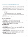
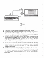
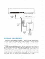
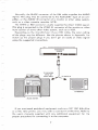
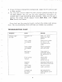
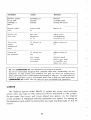
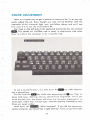
UNPACKING AND CONNECTING THE
COMMODORE 64
The following step-by-step instructions show you how to connect the
Commodore 64 to your television set, sound system, or monitor and
make sure everything is working properly.
Before attaching anything to the computer, check the contents of the
Commodore 64 container. Besides this manual, you should find the following items:
1. Commodore 64
2. Power supply (black box with an AC plug and supply cord)
3. Video cable
4. TV Switchbox (small silver box with short antenna
leads).
If any items are missing check back with your dealer immediately for
a replacement.
First, let's take a look at the arrangement of the various connections
on the computer and how each functions.
SIDE PANEL CONNECTIONS
1. Power Socket. The free end of the cable from the power supply is
attached here to supply power to the Commodore 64.
2. Power Switch. Turns on power to the Commodore 64.
3. Game Ports. Each game connector can accept a joystick or game
controller paddle, while the lightpen can only be plugged into the
game port closest to the front of your computer.
REAR CONNECTIONS
4. Cartridge Slot. The rectangular slot to the left accepts program or
game cartridges.
5. Channel Selector. Use this switch to select which TV channel the
computer's picture will be displayed on.
6. TV Connector. This connector supplies both the picture and sound to
your television set.
7. Audio & Video Output. This connector supplies direct audio, which
can be connected to a high quality sound system, and a "composite" video signal, which can be fed into a television ."monitor."
8. Serial Port. You can attach a printer or single disk drive directly to
the Commodore 64 through this connector.
2
<-Ch. 3
GAME
POWER
POWER
PORTS
SWITCH
SOCKET
Ch. 4->
CARTRIDGE CHANNEL
TV
AUDIONIDEO SERIAL CASSETTE USER
SLOT
SELECTOR CONNECTOR CONNECTOR PORT INTERFACE PORT
9. Cassette Interface. A DATASSETTErecorder can be attached
computer
time.
so you can save information entered
to the
for use at a later
10. User Port. Various interface cartridges can be attached to the user
port, such as the VICMODEM, or RS 232 communication cartridge.
INSTALLATION
CONNECTIONS
TO YOUR TV
Connect the computer to your TV as shown on page 4.
1. Attach one end of the TV cable to the phono type TV signal jack at
the rear of the Commodore 64. Just push it in. Either end of the
cable can be used.
2. Connect the other end of the cable to the antenna switchbox. Just
push it in.
3
TO
TV SIGNAL
JACK
r
TV
SWITCH BOX
Q
TO 300 OHM
INPUT
ANTENNA
POWER
SUPPLY
3. If you have a VHF antenna, disconnect it from your TV set..
4. Connect your VHF antenna cable to the screw terminals labeled "antenna input" on the switchbox. If your antenna cable is the round
75-ohm coax type, use a 75-ohm to 300-ohm adapter (not supplied)
to attach your antenna cable to the switchbox.
5. Connect the twin lead output cable of the antenna switchbox to the
VHF antenna terminals of your TV set. If your set is one of the newer
types with a round 75-ohm VHF connector, 'you will need a 300-ohm
to 75-ohm converter (not supplied) to connect the switchbox to the
75-ohm VHF antenna input on the set.
6. Set the TV's VHF tuner to the channel number indicated on the computer's channel selector switch (channel 3 move the switch to the left,
channel 4
move
the switch to the right). If a strong local TVsignal is
present on one of these channels, select the other channel to avoid
possible interference.
8. Plug the power supply cable into the power socket on the side of the
Commodore 64. Just push it in. It is "keyed" to allow insertion in only
one direction, so you can't connect the power cord the wrong way.
The power supply converts household current into the form the computer uses.
4
75 OHM TO
300 OHM
1
ADAPTER
YOUR 75 OHM
----
COAX VHF ANTENNA
The Commodore 64 is now correctly connected. No additional connections are required to use the computer with your TV. The antenna
switchbox will connect the computer to the TV when the slide switch is in
the "computer" position. When the switch is in the "TV" position your set
will operate normally.
5
TO
TV SIGNAL
JACK
t
BACK OF YOUR TV
OPTIONAL CONNECTIONS
Since the Commodore 64 furnishes a channel of high fidelity sound,
you may wish to play it through a quality amplifier to realize the best
sound possible. In addition, the Commodore 64 also provides a standard "composite" video signal, which can be fed into a television
monitor.
These options are made possible by the audio/video output jack on
the rear panel of the Commodore 64. The easiest way to gain access to
these signals is by using a standard
S-Pin DIN audio cable (not
supplied). This cable connects directly to the audio/video connector on
the computer. Two of the four pins on the opposite end of the cable
contain the audio and video signals. Optionally, you can construct your
own cable, using the pinouts shown in Appendix I as a guide.
6
Normally, the BLACK connector of the DIN cable supplies the AUDIO
signal. This plug may be connected to the AUXILIARY input of an amplifier, or the AUDIO IN connector of a monitor or other video system,
such as a video cassette recorder (VCR).
The WHITE or RED connector
usually supplies the direct VIDEO signal.
This plug is connected to the VIDEO IN connector of the monitor or video
input section of some other video system, such as a VCR.
Depending on the manufacturer
of your DIN cable, the color coding
of the plugs may be different.
Use the pinouts shown in Appendix I to
match up the proper plugs if you don't get an audio or video signal
using the suggested connections.
~--
AUDJONIDEO
OUTPUT
..
TO AUXILIARY
INPUTOR
*
TUNERINPUT ~O
4
VIDEOIN
TV MONITOR
AUDIO SYSTEM
If you purchased
peripheral
equipment,
such as a VIC 1541 disk drive
or a VIC 1515 printer, you may wish to connect it at this time.
the user's manuals supplied with any additional
equipment
proper
procedure
for connecting
it to the computer.
7
Refer to
for the
A completed
system might look like this.
>=~
..
OPERATION
USING THE COMMODORE 64
1. Turn on the computer using the rocker switch on the right-side panel
when you're looking at the computer from the front.
2. After a few moments the following will be displayed on the TV
screen:
8
--
---
3. If your TV has a manual fine tuning knob, adjust the TV until you get
a clear picture.
4. You may also want to adjust the color and tint controls on the TV for
the best display. You can use the color adjustment procedure described later to get everything setup properly. When you first get a
picture, the screen should appear mostly dark blue, with a light
blue border and letters.
If you don't get the expected
tions. The accompanying
chart
results, recheck the cables and connecwill help you isolate any problem.
TROUBLESHOOTINGCHART
Cause
I
Remedy
Symptom
Indicator light
not "On"
Computer
"On"
Make sure power
switch is in "On"
not
position
Power cable
Check power socket
for loose or dis-
not plugged
in
connected
coble.
power
Power supply
not plugged
in
Check connection
with wall outlet
Bad fuse in
Take system to
authorized dealer
computer
for replacement
fuse
of
Check other
TV on wrong
channel
channel
for
picture (3 or 4)
Incorrect
Computer hooks up to
VHF antenna terminals
hookup
Video coble
Check TV output
cable connection
not plugged
in
Computer
Set computer for
some channel as TV
set
for wrong
channel
(3 or 4)
9
.
Cause
Symptom
Random pattern
on TV with
cartridge
place
in
Picture without
color
Cartridge
properly
inserted
Remedy
Reinsert
not
cartridge after
turning off power
Poorly tuned
TV
Retune TV
Picture with
Bad color
poor color
adjustment
on TV
Adjust color!
hue/brightness
controls on TV
Sound with
excess
TV volume up
high
Adjust volume of
TV
TV volume too
low
Adjust volume of
TV
Aux. output
not properly
connected
Connect sound
background
noise
Picture OK,
but no sound
TIP: The COMMODORE 64 was designed
jack to aux. input
on amplifier and
select aux. input
to be used by everyone.
But we at Commodore recognize that computer users may, occasionally, run into
difficulties. To help answer your questions and give you some fun programming
ideas, Commodore has created several publications to help you. You might also find
that it's a good idea to join a Commodore Users Club to help you meet some other
COMMODORE 64 owners who can help you gain knowledge and experience.
CURSOR
The flashing square under READYis called the cursor and indicates
where what you type on the keyboard will be displayed" on the screen.
As you type, the cursor will move ahead one space, as the original
cursor position is replaced with the character you typed. Try typing on
the keyboard and watch as characters you type are displayed on the TV
screen.
10
COLOR
ADJUSTMENT
There is a simple way to get a pattern
of colors on the TV so you can
easily adjust the set. Even though you may not be familiar
with the
operation
of the computer
right now, just follow along, and you'll see
how easy it is to use the Commodore
64.
First, look on the left side of the keyboard and locate the key marked
1iIII. This
keys,
stands for ConTRoL and is used, in conjunction
to instruct the computer
to do a specific task.
ami
with other
To use a control function, you hold down the
key while depressing a second key.
key while also depressing thellkey.
Then reTry this: hold the
lease both keys. Nothing obvious should have happened,
but if you
touch any key now, the screen will show the character displayed in reverse type, rather than normal type-like
the opening message or anything you typed earlier.
Hold down the L'I:Hlli8:H:1
. What happens?
If you did the above procedure correctly, you should see a light blue bar move across the screen
ami
11
and then move down to the next line as long as the 1-"l:I~tll::8:J,':1
is depressed.
_
Now, hold _while
depressing
any of the other number keys. Each
of them has a color marked on the front. Anything displayed
from this
point will be in that color. For example,
release
both.
hold
Now hold the 1-"l:I~tll::8:J,':I.
_
Watch the display.
The bar is now in yellow!
and theDkey
In a like manner
change the bar to any of the other colors indicated
and the appropriate key.
by holding
and
you can
on the number
keys
Change the bar to a few more different colors and then adjust the
color and tint controls on your TV so the display matches the colors you
selected.
The display
should
appear
something
like this:
At this point everything is properly adjusted and working correctly.
The following chapters will introduce you to the BASIC language. However, you can immediately start using some of the many prewritten applications and games available for the Commodore 64 without knowing
anything about computer programming.
Each of these packages contains detailed information about how to
use the program. It is suggested, though, that you read through the first
few chapters of this manual to become more familiar with the basic
operation of your new system.
12