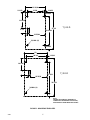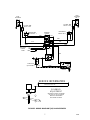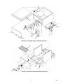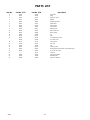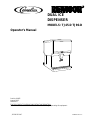
1
DUAL ICE
DISPENSER
MODELS: TJ45-D TJ90-D
Operator’s Manual
Part No. 90665
August 1995
Revision B
THIS DOCUMENT CONTAINS IMPORTANT INFORMATION
This Manual must be read and understood before installing or operating this equipment
â REMCOR INC:
PRINTED IN U.S.A
TABLE OF CONTENTS
Page
SAFETY PRECAUTIONS . . . . . . . . . . . . . . . . . . . . . . . . . . . . . . . . . . . . . . . . . . . . . . . . . . .
1
GENERAL DESCRIPTION . . . . . . . . . . . . . . . . . . . . . . . . . . . . . . . . . . . . . . . . . . . . . . . . . .
1
INSTALLATION INSTRUCTIONS . . . . . . . . . . . . . . . . . . . . . . . . . . . . . . . . . . . . . . . . . . . .
2
OPERATOR INSTRUCTION . . . . . . . . . . . . . . . . . . . . . . . . . . . . . . . . . . . . . . . . . . . . . . . . .
2
OPERATING INSTRUCTIONS . . . . . . . . . . . . . . . . . . . . . . . . . . . . . . . . . . . . . . . . . .
CLEANING INSTRUCTIONS . . . . . . . . . . . . . . . . . . . . . . . . . . . . . . . . . . . . . . . . . . . .
DISPENSER . . . . . . . . . . . . . . . . . . . . . . . . . . . . . . . . . . . . . . . . . . . . . . . . . . . . . . . . .
MAINTENANCE . . . . . . . . . . . . . . . . . . . . . . . . . . . . . . . . . . . . . . . . . . . . . . . . . . . . . . . . . . .
2
2
2
4
DAILY OR AS REQUIRED . . . . . . . . . . . . . . . . . . . . . . . . . . . . . . . . . . . . . . . . . . . . . .
4
WEEKLY OR AS REQUIRED . . . . . . . . . . . . . . . . . . . . . . . . . . . . . . . . . . . . . . . . . . . .
MONTHLY . . . . . . . . . . . . . . . . . . . . . . . . . . . . . . . . . . . . . . . . . . . . . . . . . . . . . . . . . . . .
TOUBLESHOOTING . . . . . . . . . . . . . . . . . . . . . . . . . . . . . . . . . . . . . . . . . . . . . . . . . . . . . . .
4
4
5
BLOWN FUSE OR CIRCUIT BREAKER . . . . . . . . . . . . . . . . . . . . . . . . . . . . . . . . . .
GATE DOES NOT OPEN. AGITATOR DOES NOT TURN. . . . . . . . . . . . . . . . . . .
GATE NOES NOT OPEN OR IS SLUGGISH. AGITATOR TURNS. . . . . . . . . . . .
5
5
5
GATE OPENS. AGITATOR DOES NOT TURN. . . . . . . . . . . . . . . . . . . . . . . . . . . . .
ICE DISPENSES CONTINUOUSLY. . . . . . . . . . . . . . . . . . . . . . . . . . . . . . . . . . . . . . .
SLUSHY ICE. WATER IN HOPPER. . . . . . . . . . . . . . . . . . . . . . . . . . . . . . . . . . . . . . .
PARTS LIST . . . . . . . . . . . . . . . . . . . . . . . . . . . . . . . . . . . . . . . . . . . . . . . . . . . . . . . . . . . . . .
5
5
5
11
WARRANTY . . . . . . . . . . . . . . . . . . . . . . . . . . . . . . . . . . . . . . . . . . . . . . . . . . . . . . . . . . . . . .
13
LIST OF FIGURES
FIGURE 1. MOUNTING TEMPLATES . . . . . . . . . . . . . . . . . . . . . . . . . . . . . . . . . . . .
6
FIGURE 2. WIRING DIAGRAM TJ45, 90-D DISPENSER . . . . . . . . . . . . . . . . . . .
FIGURE 3. EXPLODED VIEW UPPER SECTION TJ45 . . . . . . . . . . . . . . . . . . . .
FIGURE 4. EXPLODED VIEW LOWER SECTION TJ45 TJ90 . . . . . . . . . . . . . . .
FIGURE 5. EXPLODED VIEW UPPER SECTION TJ90 . . . . . . . . . . . . . . . . . . . . .
FIGURE 6. SOLENOID ASSEMBLY . . . . . . . . . . . . . . . . . . . . . . . . . . . . . . . . . . . . . .
7
8
9
10
12
LIST OF TABLES
TABLE 1. SPECIFICATIONS . . . . . . . . . . . . . . . . . . . . . . . . . . . . . . . . . . . . . . . . . . . .
1
Manufactured Under One or More of the Following Patent Numbers:
3,211,336, 3,274,792, 3,393,839 , 3,517,860, 3,739,842, 4,215,803, 4,227,377, 4,300,3594,346,824
Canadian Patent Numbers912,514 (10/72), 936,855 (11,73), 4,429,543, 4,921,149
Other Patents Pending
i
90665
SAFETY PRECAUTIONS
Always disconnect power to the dispenser before servicing or cleaning.
Never place hands inside of hopper or gate area without disconnecting power to the dispenser. Agitator rotation
occurs automatically when the dispenser is energized!
This ice dispenser has been specifically designed to provide protection against personal injury and eliminates
contamination of ice. To insure continued protection and sanitation, observe the following
ALWAYS be sure the removable lid is properly installed to prevent
unauthorized access to the hopper interior and possible contamination of ice.
ALWAYS be sure the upper and lower front panels are securely fastened.
ALWAYS keep area around the dispenser clean of ice cubes.
CAUTION: Dispenser cannot be used with crushed or flaked ice.
Use of bagged ice which has frozen into large chunks can void warranty. The dispenser
agitator is not designed to be an ice crusher. Use of large chunks of ice which “jam up”
inside the hopper will cause failure of the agitator motor and damage to the hopper. If bagged ice
is used, it must be carefully and completely broken into small, cube-sized pieces before filing into
the dispenser hopper.
GENERAL DESCRIPTION
The Remcor “TJ”series of ice dispensers will solve ice service needs in the sanitary, space saving, economical
way. Designed to be manually filled with ice from any remote ice making source, these dispensers will dispense
cubes (up 1”in size), cubelets, hard-chipped or cracked ice.
Table 1. Specifications
Model:
Ice Storage Capacity:
Electrical:
Drain Connection:
Electrical Connection:
Dimensions:
TJ45-D
45 lbs.
120/1/60 3AMP
3/4” F.P.T.
6’, 3-wire cord with 3-prong ground-type plug
26½ ”H x 16”W x 22”D
Model:
Ice Storage Capacity:
Electrical:
Drain Connection:
Electrical Connection:
Dimensions:
TJ90-D
90 lbs.
120/1/60 3AMP
3/4” F.P.T.
6’, 3-wire cord with 3-prong ground-type plug
30”H x 22” W x 28”D
CAUTION: Dispenser cannot be used with crushed or flaked ice. Use of bagged ice, which
has frozen into large chunks can void warranty. The dispenser agitator is not designed to
be an ice crusher -- use of large chunks of ice which “jam--up” inside the hopper will cause
failure of the agitator motor and damage to the hopper. If bagged ice is used it must be carefully
and completely broken into small, cube-size pieces before filling into the dispenser hopper.
1
90665
INSTALLATION INSTRUCTIONS
1. *Locate the dispenser indoors on a level counter top, unpack 4 legs and install them into the threaded
holes provided in the bottom of the unit.
2. Connect 3/4”IPS (or equal) drain line to the 3/4”threaded drain connections at the lower rear of the unit.
This line must pitch downward to an open drain, and must contain no traps, or improper drainage will
result.
3. Clean the hopper interior (see cleaning instructions).
4. Connect the power cord to a 120 volt, 60 Hz. 3-wire grounded receptacle.
Unit is now ready for operation.
NOTE:
*Figure 1, page 6 provides mounting template for those who desire to mount dispensers on a
counter.
NOTE:
Water pipe connections and fixtures directly connected to a potable water supply shall be
sized, installed and maintained according to Federal, State, and Local Laws
OPERATOR INSTRUCTION
OPERATING INSTRUCTIONS
Fill the hopper with ice and replace the lid. Pushing the dispense lever will cause ice to flow from the ice chute.
Ice flow will continue until the lever is released. If ice does not dispense, see the “Troubleshooting Guide”to fine
the cause
CAUTION: Use caution to avoid spilling ice when filling dispenser. Clean up immediately
and spilled ice from filling or operating the unit. To prevent contamination of ice, the lid
must be installed on the unit at all times.
CLEANING INSTRUCTIONS
WARNING: Disconnect power before cleaning. Do not use metal scrapers, sharp objects,
or abrasives on the surface of the liner as damage may result. Do not use solvents or other
cleaning agents, as they may attack the plastic liner.
Dispenser
1. Clean the ice dispenser interior at lease once a month.
2. Remove agitator assembly and wash and rinse it thoroughly.
3. Wash down the inside of hopper and top cover with mild detergent solution and rinse thoroughly to remove
all traces of detergent.
4. Replace agitator.
90665
2
5. Sanitize the inside of hopper and agitator with a solution of 1/2 ounce household bleach in 1 gallon of
water. (200 PPM)
6. Remove Ice chute cover as follows:
A.
Flex sides outward to disengage lower pins.
B.
Lift Ice Chute cover to disengage upper pins.
C.
Lower Ice Chute cover down out of unit. Note: It may be helpful to twist cover slightly.
7. Clean the inside of the ice chute and ice chute cover with a mild detergent solution and rinse thoroughly to
remove all traces of detergent.
8. Reverse steps above to reassemble ice chute.
9. Sanitize as descried in step 5.
3
90665
MAINTENANCE
The following dispenser maintenance should be performed at the intervals indicated:
DAILY or as required
Remove foreign material from the vending area sink to prevent drain blockage.
WEEKLY or as required
Clean vending area. Check for proper water drainage from the vending area sink.
MONTHLY
Clean and sanitize the hopper interior (see CLEANING INSTRUCTIONS).
If the dispenser fails to dispense ice when operated, check that the hopper has ice in it and that power is being
supplied to the unit. If the problem persists, check the following:
1. Determine if the agitator is rotating (check for the sound of ice movement in the hopper).
2. Observe whether the gate is operating.
After checking the above, refer to the TROUBLESHOOTING GUIDE for possible problem causes and
corrective action.
CAUTION: Use caution to avoid spilling ice when filling dispenser. Clean up immediately
any spilled ice from filling or operating the unit. To prevent contamination of ice, the lid
must be installed on the unit at all times.
90665
4
TOUBLESHOOTING
IMPORTANT: only qualified personnel should service internal components.
Should your unit fail to operate properly, check that the electric plug is secure, and that the hopper contains ice.
If the unit still does not dispense, check the following chare under the appropriate symptoms to aid in locating
the defect.
Trouble
Probable Cause
BLOWN FUSE OR CIRCUIT BREAKER.
GATE DOES NOT OPEN. AGITATOR DOES NOT
TURN.
GATE NOES NOT OPEN OR IS SLUGGISH.
AGITATOR TURNS.
GATE OPENS. AGITATOR DOES NOT TURN.
ICE DISPENSES CONTINUOUSLY.
SLUSHY ICE. WATER IN HOPPER.
5
A.
Short circuit in wiring.
B.
Defective gate solenoid.
C.
Defective agitator motor.
A.
No power.
B.
Defective dispensing switch.
C.
Bent depressor lever (does not actuate switch).
A.
Excessive pressure against gate slide.
B.
Defective gate solenoid.
C.
Weak gate spring.
A.
Ice solidified in hopper.
B.
Defective agitator motor.
C.
Defective capacitor (TJ90 only).
A.
Stuck or bent depressor lever (does not release
switch).
B.
Defective dispensing switch.
C.
Improper switch installation.
A.
Blocked drain.
B.
Unit not level.
C.
Poor ice quality due to water quality or icemaker
problem.
D.
Improper use of flake ice.
90665
15 13/16
1 19/32
12 5/8
1 19/32
2 29/32
11 13/16
27 1/2
3 7/8
TJ45-D
21 11/16
2
12 37/64
3/8 DIA. (4)
2 29/32
22
18 3/8
1 13/16
10 5/16
7
TJ90-D
27 5/32
5
15 23/32
33 5/32
3/8 DIA. (4)
3
NOTE:
SHADED AREA INDICATE OPENINGS IN
CABINET BOTTOM NEEDED FOR UTILITIES,
OR BEVERAGE TUBING WHEN APPLICABLE.
FIGURE 1. MOUNTING TEMPLATES
90665
6
GATE
SOLENOID
NO. 2
GATE
SOLENOID
NO. 1
1 1/4 AMP TIME
DELAY FUSE
1 1/4 AMP TIME
DELAY FUSE
DISPENSING
SWITCH NO. 2
TERMINAL
BOARD
DISPENSING
SWITCH NO. 1
RED
YEL
RED
BLK
BLK
WHT
WHT
120V 60HZ
POWER
CORD
L1
L2
GND
OR
WHT
RELAY
CAPACITOR
(TJ90-D ONLY)
RED
BLU
AGITATOR
MOTOR
SERVICE INFORMATION
7
DANGER!
ELECTRIC SHOCK HAZARD. DISCONNECT POWER
BEFORE SERVICING UNIT.
8
SOLENOID
ADJUSTMENT
WHEN REPLACING SOLENOID
ADJUST TO 7/8 AS SHOWN
BEFORE TIGHTENING
MOUNTING SCREWS
FIGURE 2. WIRING DIAGRAM TJ45, 90-D DISPENSER
7
90665
4
12
22
10
11
15
8
14
1
2
FIGURE 3. EXPLODED VIEW UPPER SECTION TJ45
16
5
6
7
13
3
17
24
FIGURE 4. EXPLODED VIEW LOWER SECTION TJ45
90665
8
9
4
12
10
11
9
15
1
22
21
8
14
2
FIGURE 5. EXPLODED VIEW UPPER SECTION TJ90
16
5
13
7
3
24
6
17
FIGURE 6. EXPLODED VIEW LOWER SECTION TJ90
9
90665
PARTS LIST
Item No.
Part No. TJ45
Part No. TJ90
Description
1
21491
21491
2
31206
31206
Relay
3
21515
21515
Depressor Lever
Gate Slide
4
21517
21629
Agitator
5
30895
30895
Dispensing Switch
6
31007
31007
Switch Boot
7
31163
31163
Switch Insert
8
23062
23062
Foam Shield
9
31106
31112
Agitator Motor
10
50454
50454
Motor Shaft Seal
11
50481
50806
Motor Gasket
12
50880
50885
Lid
13
50750
50793
Sink
14
53015
53015
Ice Chute Back Section
53016
53016
Ice Chute Cover
15
50770
50770
Gate Gasket
16
70426
70441
Sink Grill
17
70419
70419
Leg
18
90295
90295
Cleaning Label
19
90615
90615
Wiring Diagram (Not Shown on Exploded View)
20
90616
90628
“Press for Ice”Label
21
----------
30774
Capacitor
22
31093
31093
Solenoid Assembly
23
70438
70438
Rebuilding Kit
24
22644
22644
Depressor Retainer
90665
10
1
2
22
4
3
5
4
22
6
19
18
22
20
21
8
16
15
14
11
10
17
19
13
9
12
7
FIGURE 7. SOLENOID ASSEMBLY
Index
No.
Part No.
Qty.
Name
1
21493
1
2#
31551
1
Solenoid Mounting Plate
Solenoid Service Kit
3
70171
2
8--32 x 3/8 Phil Tr HD Screw
4
70121
2
No. 8 Lockwasher
5
50752
3
Isolator
6*
50789
2
Bumper Assembly
7*
70423
1
Cotter Pin
8*
10080
1
Gate Lift Rod
9
10081
1
Gate Lift Rod Bushing
10
50754
1
Gate Arm Bearing
Gate lift Arm
11
21492
1
12
70043
1
Flatwasher
13*
70422
1
Spring
14
70263
1
1/4-20 x 3/4 Hex Hd Screw
15
70048
1
1/4 Lockwasher
16
70066
1
1/4 Flatwasher
17
10077
1
Pivot Bearing
18
30227
1
1/4 Quick Connect Tab
19
50305
----
Lubricant
20*
21592
1
Solenoid Linkage Pin
21*
70433
2
Retainer Ring
22
51088
----
Loctite
----*
70438
----
Rebuilding Kit
NOTE: * Parts supplied with rebuilding kit.
# 31551 solenoid supplied with items 20 & 21.
11
90665
IMI CORNELIUS INC.
ONE CORNELIUS PLACE
ANOKA, MN. 55303--6234
TELEPHONE (800) 238--3600
FACSIMILE (612) 422--3232
TECH SVC 1-800-535-4240
WARRANTY
IMI Cornelius Inc. and Remcor Products Company warrants that all equipment and parts are free from defects
in material and workmanship under normal use and service. For a copy of the warranty applicable to your
Cornelius and or Remcor product, in your country, please write, fax or telephone the IMI Cornelius office nearest you. Please provide the equipment model number, serial number and the date of purchase.
IMI Cornelius Offices
AUSTRALIA D P.O. 210, D RIVERWOOD, D NSW 2210, AUSTRALIA D (61) 2 533 3122 D FAX (61) 2 534 2166
AUSTRIA D AM LANGEN FELDE 32 D A-1222 D VIENNA, AUSTRIA D (43) 1 233 520 D FAX (43) 1-2335-2930
BELGIUM D BOSKAPELLEI 122 D B-2930 BRAASCHAAT, BELGIUM D (32) 3 664 0552 D FAX (32) 3 665 2307
BRAZIL D RUA ITAOCARA 97 D TOMAS COELHO D RIO DE JANEIRO, BRAZIL D (55) 21 591 7150 D FAX (55) 21 593 1829
ENGLAND D TYTHING ROAD ALCESTER D WARWICKSHIRE, B49 6 EU, ENGLAND D (44) 789 763 101 D FAX (44) 789 763 644
FRANCE D 71 ROUTE DE ST. DENIS D F-95170 DEUIL LA BARRE D PARIS, FRANCE D (33) 1 34 28 6200 D FAX (33) 1 34 28 6201
GERMANY D CARL LEVERKUS STRASSE 15 D D-4018 LANGENFELD, GERMANY D (49) 2173 7930 D FAX (49) 2173 77 438
GREECE D 488 MESSOGION AVENUE D AGIA PARASKEVI D 153 42 D ATHENS, GREECE D (30) 1 600 1073 D FAX (30) 1 601 2491
HONG KONG D 1104 TAIKOTSUI CENTRE D 11-15 KOK CHEUNG ST D TAIKOKTSUE, HONG KONG D (852) 789 9882 D FAX (852) 391 6222
ITALY D VIA PELLIZZARI 11 D 1-20059 D VIMARCATE, ITALY D (39) 39 608 0817 D FAX (39) 39 608 0814
NEW ZEALAND D 20 LANSFORD CRES. D P.O. BOX 19-044 AVONDALE D AUCKLAND 7, NEW ZEALAND D (64) 9 8200 357 D FAX (64) 9 8200 361
SINGAPORE D 16 TUAS STREET D SINGAPORE 2263 D (65) 862 5542 D FAX (65) 862 5604
SPAIN D POLIGONO INDUSTRAIL D RIERA DEL FONOLLAR D E-08830 SANT BOI DE LLOBREGAT D BARCELONA, SPAIN D (34) 3 640 2839 D FAX (34) 3 654 3379
USA D ONE CORNELIUS PLACE D ANOKA, MINNESOTA D (612) 421-6120 D FAX (612) 422-3255
12
Manual number
IMI CORNELIUS INC.
Corporate Headquarters:
One Cornelius Place
Anoka, Minnesota 55303-6234
Telephone (800) 238-3600
Facsimile (612) 422-3246