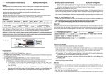
1
IPC Series
IPC-DT/L400(PC)A,
IPC-DT/L400(PC)TA,
IPC-DT/L400(PC)TB
User’s Manual
CONTEC CO.,LTD.
Copyright
Copyright 2000 CONTEC Co., LTD. ALL RIGHTS RESERVED
No part of this document may be copied or reproduced in any form
by any means without prior written consent of CONTEC Co., LTD.
CONTEC Co., LTD. makes no commitment to update or keep
current the information contained in this document. The
information in this document is subject to change without notice.
All relevant issues have been considered in the preparation of this
document. Should you notice an omission or any questionable
item in this document, please feel free to notify CONTEC Co.,
LTD.
Regardless of the foregoing statement, CONTEC assumes no
responsibility for any errors that may appear in this document nor
for results obtained by the user as a result of using this product.
Trademarks
MS, Microsoft, MS-DOS Windows and Windows NT are
trademarks of Microsoft Corporation. Other brand and product
names are trademarks of their respective holder.
User’s Manual
i
Table of Contents
Copyright ........................................................................... i
Trademarks........................................................................ i
Table of Contents.............................................................. ii
1. Introduction......................................................................1
Limited One-Year Warranty ....................................... 3
How to Obtain Service ................................................. 3
Liability ....................................................................... 3
Handling Precautions .................................................. 4
2. Specifications....................................................................7
Function Specifications .................................................... 7
General Specifications ..................................................... 8
Display Optical Specifications ......................................... 9
3. Dimensions and Names of Parts....................................11
Case External Dimensions .........................................11
Part Names................................................................. 12
4. Installation .....................................................................13
Installation Cautions ..................................................... 15
5. Connecting with Host Computer ...................................17
VGA Mode Setting.......................................................... 17
System Configuration and Connection ......................... 19
6. Touch Panel ....................................................................21
ii
User’s Manual
1. Introduction
1. Introduction
The display is a 12.1inch, desktop TFT LCD for use with a host
computer, such products as the CONTEC IPC series and SBC
(single-board computer). The display is available in three
different models; the IPC-DT/L400(PC)A not installed with the
touch-panel feature, the IPC-DT/L400(PC)TA installed with the
touch-panel feature, and the IPC-DT/L400(PC)TB with a polarizer
attached to the (low-reflection and high-contrast) touch panel.
- Large 800 x 600 dot display screen (12.1inch) that is optimum for
use with Windows.
- Wide-viewing angle and high-brilliance type
- Displays a maximum of 262,144 colors
- Equipped with a quick-response, analog touch panel
[IPC-DT/L400(PC)TA, IPC-DT/L400(PC)TB]
- Digital RGB I/F
- A variety of host computers
This display works with the following host computers:
For connectivity information for other products than IPCs and
SBCs described here, see the CONTEC’s Product Catalog or visit
the CONTEC’s Web site or contact your retailer.
-
-
IPC series
- IPC-BX/M560(PCW)E
- IPC-BX/M560(PCW)C
- IPC-BX/M560(PCW)EP
- IPC-BX/M560(PCW)CP
- IPC-BX/M400(PC)H
- IPC-BX/P400(PC)
- IPC-UP/M500(PCW)H
- IPC-UP/M500(PCW)
- PC-LCD(PCI)T
SBC (single-board computer) series
- PC-686E(PC)-266
- PC-686E(PC)-333
- PC-586HU(PC)-LV
- PC-486HU(PC)-LV
* To use this display with the SBC series, you need the
"ADPLCD(PC)H" ISA expansion board.
User’s Manual
1
1. Introduction
- Various options are available:
- IPC-M4CL-2H
: Cable for connecting the flat-panel display
installed with no touch-panel feature (2m)
For the "IPC-BX/M400(PC)H"
- IPC-M4CL-2TH : Cable for connecting the flat-panel display
installed with the touch-panel feature (2m)
For the "IPC-BX/M400(PC)H"
- IPC-P4CL-2H
: Flat panel display connection cable (2m)
- ADPLCD(PC)H : ISA expansion board to allow display with
the SBC (single-board computer).
- IPC-TPB1-DRV : Touch panel driver for the
"IPC-BX/M400(PC)H" and other models
- IPC-TPB2-DRV : Touch panel driver for the
"IPC-BX/M560(PCW)" series and "SBC"
- IPC-SND-02
: Stand kit for using the main unit as a desktop
machine
- IPC-CV12
: Protective sheet for 12.1inch screen
* For more information about each host computer and option, see
the "Product Guide" or contact a CONTEC branch or a sales
representative.
2
User’s Manual
1. Introduction
Limited One-Year Warranty
CONTEC Interface boards are warranted by CONTEC CO., LTD.
to be free from defects in material and workmanship for up to one
year from the date of purchase by the original purchaser.
Repair will be free of charge only when this device is returned
freight prepaid with a copy of the original invoice and a Return
Merchandise Authorization to the distributor or the CONTEC group
office, from which it was purchased.
This warranty is not applicable for scratches or normal wear, but
only for the electronic circuitry and original boards. The warranty
is not applicable if the device has been tampered with or damaged
through abuse, mistreatment, neglect, or unreasonable use, or if the
original invoice is not included, in which case repairs will be
considered beyond the warranty policy.
How to Obtain Service
For replacement or repair, return the device freight prepaid, with a
copy of the original invoice. Please obtain a Return Merchandise
Authorization Number (RMA) from the CONTEC group office
where you purchased before returning any product.
* No product will be accepted by CONTEC group without the
RMA number.
Liability
The obligation of the warrantor is solely to repair or replace the product.
In no event will the warrantor be liable for any incidental or
consequential damages due to such defect or consequences that arise
from inexperienced usage, misuse, or malfunction of this device.
User’s Manual
3
1. Introduction
Handling Precautions
In order to enjoy your FLAT PANEL DISPLAY for a long time,
please be sure to read the following precautions before using the
display.
- This display is made of the precise electric parts, so do not use or
store it in the vicinity of impulse or vibration.
- This product is not intended for use in aerospace, space, nuclear
power, medical equipment, or other applications that require a
very high level of reliability. Do not use the product in such
applications.
- If you utilize this product in such usages where high reliability
and safety are required as on the trains, vessels, automotives or
crime- or disaster-prevention devices, contact your retailer.
- Do not use or store the product in a location exposed to extremely
high or low temperature or susceptible to rapid temperature
changes.
Example:
- Exposure to direct sun
- In the vicinity of a heat source
- Do not use the product in extremely humid or dusty locations.
- Display brightness deteriorates with use. Backlight life (50% of
initial brightness) is 50,000 hours (at continuous operation at
25°C).
- Do not use sharp objects, such as a pencil tip, to operate the touch
panel. Doing so may damage the panel and cause a malfunction.
- Protect the touch panel from being shaken or struck as this may
cause damage.
- If the touch panel surface or frame becomes dirty, wipe them
clean with a neutral detergent. Do not wipe them with thinner,
ammonia, or strong chloride solvent. In addition, when using
the touch panel in an environment where the touch panel can
easily become dirty, place use a protective sheet (option).
- Absolutely do not disconnect the display cable while the host
computer power is turned on. Only plug in or disconnect the
cable after turning off the host computer power or damage could
result.
- This monitor does not support MS-DOS. Another CONTEC
product PC-LCD(PCI)T supports neither MS-DOS nor Windows
3.1.
- The display cable connector has a rotating construction, but it was
not designed to be frequently rotated. Do not rotate it frequently
or damage could result.
4
User’s Manual
1. Introduction
- As one of analog, touch-panel characteristics, detection positions
might slide out of place due to an ambient change (in temperature
and/or humidity) or as time elapses. If you experience this,
recalibrate the touch panel and re-set calibration data.
- If you utilize this product in such usages where high reliability
and safety are required as on the trains, vessels, automotives or
crime- or disaster-prevention devices, contact your retailer.
User’s Manual
5
1. Introduction
6
User’s Manual
2. Specifications
2. Specifications
Function Specifications
Table 2.1.
Item
Function Specifications
IPC-DT/L400(PC)A
IPC-DT/L400(PC)TA
Installation type
Desktop, wall hanging *1
Display size
12.1 inch
Dot configuration
800 dots horizontal x 600 dots vertical
Display device
TFT color liquid crystal display
Display colors
262,144 colors
IPC-DT/L400(PC)TB
Brightness control
Adjustable with the volume on the side
Backlight control
Possible (software controlled)
Cable length
2m (use the special-purpose display cable sold separately.)
Touch panel
Resolution
-
1024 x 1024 (emulated at 800 x 600)
Detection method
-
Resistance film analog method
Strong life
-
More than a million times
(Load: 300gf±100gf, Speed: 2 times/sec,
by mechanical keying in)
Touch panel interface
Polarizer *2
Power consumption
-
50-core, half-pitch connector on the back
(shared with display signals)
-
No
Yes
+5VDC 2.7A (Max.)
*1 When using on the Desktop, the optional stand IPC-SND-02 is required
*2 The IPC-DT/L400(PC)TB with a touch-panel installed with a polarizer offers low reflection and high
contrast.
(Note that brightness is reduced by 9% compared with the touch panel not installed with the polarizer.)
User’s Manual
7
2. Specifications
General Specifications
Table 2.2.
General Specifications
Item
Specification
Environment
Ambient operating temperature
0 - 45°C
Ambient storage temperature
-10 - 60°C
Ambient humidity
20% - 90% RH
Floating dust
Not severe
Corrosive gas
none
Noise
resistance
Line noise
Signal line /1kV(IEC1000-4-4 Level3, EN61000-4-4 Level3)
(When using the host PC IPC-BX/M400(PC)H)
Statistic electricity
resistance
Contact / 4kV (IEC1000-4-2 Level2, EN61000-4-2 Level2)
Airborne / 8kV(IEC1000-4-2 Level3, EN61000-4-2 Level3)
Structure
Major dimensions (mm)
320(W) x 35(D) x 272(H)
Weight
About 1.6kg
8
User’s Manual
2. Specifications
Display Optical Specifications
Table 2.3.
Display Optical Specifications
Item
Condition
φ = 180°
Visual angle
(vertical)
Visual angle
CR≥10
(horizontal)
Standard
50deg
φ = 0°
Display in
40deg
70deg
φ = +90°
monochrome
40deg
70deg
40deg
70deg
φ= -90°
Surface
brightness
Min.
30deg
Display in white
280cd/m2 350cd/m2
(at center)
Contrast ratio (CR) =
Brightness at screen center with white displayed
Brightness at screen center with black displayed
Measurement direction
Z
( θ = 0°)
Left
( φ = -90°)
θ
Up
( φ = 180°)
X
φ
Module
Down
( φ = 0°)
Right
( φ = 90°)
Y
Figure 2.1. Definition of viewable area
Note!
Optical specification data represent optical characteristics of the
LCD installed on the device, which are different from the actual
view or view angles.
User’s Manual
9
2. Specifications
10
User’s Manual
3. Dimensions and Names of Parts
3. Dimensions and Names of Parts
Case External Dimensions
35
16
320
12
96
127
127
Display center
28
Device center
11
96
272
28
86
262
310
83
[mm]
Figure 3.1. Case External Dimensions
User’s Manual
11
3. Dimensions and Names of Parts
Part Names
LCD screen
* IPC-DT/L400(PC)A : Dummy glass
* IPC-DT/L400(PC)TA , IPC-DT/L400(PC)TB :Touch panel
Power
LED
Brightness adjustment dial
How to adjust brightness
* Turn the volume upward to increase brightness.
Turn the volume downward to reduce brightness.
Bright
Dark
LCD connector
Figure 3.2. Part Names
12
User’s Manual
4. Installation
4. Installation
There are two methods of installation.
Both are described below.
(1) Hanging with screws
Install M4 size round head or binding screws at the 4 wall
locations shown by the following dimensions. The panel can
be hung more securely on screws with larger head diameters.
Wall surface
200
87
2.2mm
164
M4 screw
To select screws of the
appropriate length give
sufficient consideration
to the thickness of the
wall material and the
weight of the display.
77
Display center
100
100
Figure 4.1. Screw Installation Locations
Hang the display by the 4 installation holes on the corresponding
screws.
Installation hole x 4
R6
R2.25
8
4.5
Figure 4.2. Installation Holes
User’s Manual
13
4. Installation
(2) Fastening the back of the panel with screws.
Make 4mm holes in the 6 locations on the back of panel shown
by the dimensions below.
116
138
12
Center of
display screen
69
116
69
Center of device
[mm]
Figure 4.3. Hole Locations
Fasten the display by the 6 installation holes using M3 screws.
Note that the maximum depth of the display screw holes is 4mm.
M3 x 5mm x 6
4mm
side view
M3 screws
Panel
Display
Figure 4.4. Installation Holes
14
User’s Manual
4. Installation
Installation Cautions
(1) Dimension restriction when mounting in a recessed wall
location
50mm
Front
LCD cable
Side view
Figure 4.5. Mounting in a Recessed Wall Location
(2) Bending limit for LCD cable
20mm
60mm or more
Figure 4.6. Bending Limit for LCD Cable
User’s Manual
15
4. Installation
16
User’s Manual
5. Connecting with Host Computer
5. Connecting with Host Computer
VGA Mode Setting
Before using the display, set the VGA mode setting on the host
computer to "TFT color 800 x 600." For each host computer, set
as described next.
If using IPC or SBC products other than those listed here, refer to
their respective manuals for details of the settings.
Notes!
- Before setting, be sure to disconnect the power to the host
computer.
- Set according to the documentation that came with the host
computer.
(If settings for this display are not included in the host
computer documentation, set according to this manual.)
(1) When you are using the IPC-BX/M400(PC)H or
IPC-BX/P400(PC):
On the BIOS "Embedded Features" setup screen, set "VGA
BIOS Select" to "800 x 600TFT." For more information
about setting, see the IPC-BX/M400(PC)H documentation.
(2) When you are using the IPC-UP/M500(PCW)H or
IPC-UP/M500(PCW):
Set the jumpers on the UPLCDS board of the device to TFT
color 800 x 600 as shown next.
JP5
1
2
JP4
1
2
JP3
1
2
JP2
1
2
JP1
1 2 3
JP1 : 2-3Short
JP2 : Short
JP3 : Open
JP4 : Short
JP5 : Open
User’s Manual
17
5. Connecting with Host Computer
(3) When you are using the IPC-BX/M560E(PCW)E,
IPC-BX/M560E(PCW)C, IPC-BX/M560E(PCW)EP,
IPC-BX/M560(PCW)CP, PC-LCD(PCI)T, PC-686E(PC)-266
or PC-686E(PC)-333, set the rotary switches inside the display
and on the circuit board to the "0 setting" (TFT color 800 x
600).
456
CDE
AB
23
F01
7 89
(4) When you are using the PC-586HU(PC)-LV:
Set the jumpers on the circuit board to TFT color 800 x 600 as
shown next:
JP8
7
8
1
2
JP8 : Open
(5) When you are using the PC-486HU(PC)-LV:
Set the jumpers on the circuit board to TFT color 800 x 600 as
shown next:
JP9
2
1
18
6
5
JP9 : Open
User’s Manual
5. Connecting with Host Computer
System Configuration and Connection
Connect this display to each host computer using the LCD
connector on the host computer and a dedicated cable. The
following diagram shows an example connection with the
IPC-BX/M400(PC)H:
Cable set
IPC-M4CL-2TH
IPC-M4CL-2H
IPC-BX/M400(PC)H
Power unit
COM cable for touch panel
(attached to IPC-M4CL-2TH)
Connection cable sold separately
When connected to an IPC-BX/M400(PC)H : IPC-M4CL-2TH (touch-panel feature installed)
IPC-M4CL-2H (touch-panel feature not installed)
When connecting to other host computers : IPC-P4CL-2H
LCD connector
Insert plog firmly,
and verify that it locks in place.
Figure 5.1. System Configuration
(When connected to an IPC-BX/M400(PC)H)
Note!
Before connecting, be sure to disconnect the power to the host
computer.
User’s Manual
19
5. Connecting with Host Computer
20
User’s Manual
6. Touch Panel
6. Touch Panel
The IPC-DT/L400(PC)TA and IPC-DT/L400(PC)TB installed with
touch-panel features are equipped with a quick-response touch
panel to allow keyboard- and mouse-less operations and performs
serial communications (RS-232C) with the host computer.
Touch panel
Figure 6.1. Touch Panel
To use the touch panel, install the touch-panel driver software
(IPC-TPB1-DRV, IPC-TPB2-DRV). This product is offered as an
option and you need to purchase it separately.
Host PC
Compatible touch-panel driver software modes
IPC-BX/M400(PC)H, IPC-BX/P400(PC)
IPC-UP/M500(PCW)H, IPC-UP/M500(PCW)
IPC-TPB1-DRV
PC-LCD(PCI)T
IPC-BX/M560(PCW)E, IPC-BX/M560(PCW)C
IPC-TPB2-DRV
IPC-BX/M560(PCW)EP, IPC-BX/M560(PCW)CP
(Windows 98/95/NT 4.0 only)
For more information about touch-panel drivers, contact a
CONTEC branch or a sales representative.
Notes!
- Brightness on this device is not adjustable with the touch-panel
driver software utility. Adjust brightness using the brightness
controller on one side of the device.
- The DOS and Windows' DOS 640 x 480 screen mode during
the full screen mode is not supported.
User’s Manual
21
IPC-DT/L400(PC)A
IPC-DT/L400(PC)TA
IPC-DT/L400(PC)TB
User’s Manual
IPC-DT/L400A-HMU
CONTEC CO.,LTD.
March 2005 Edition
3-9-31, Himesato, Nishiyodogawa-ku, Osaka 555-0025, Japan
Japanese http://www.contec.co.jp/
English
Chinese
http://www.contec.com/
http://www.contec.com.cn/
No part of this document may be copied or reproduced in any form by any means without prior written
consent of CONTEC CO., LTD.
[02232005]
[03072000]
Management No.
A-46-371
[03042005_rev2]
Parts No.
LZQ2461