1
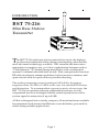
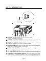
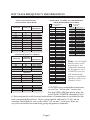
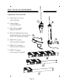
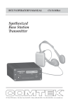
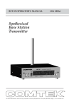
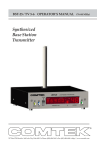
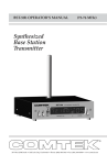
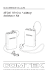
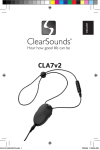
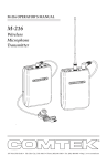
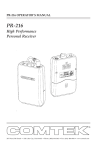
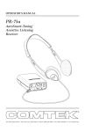
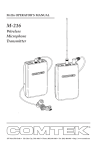
BST 75-216 OPERATOR’S MANUAL
(216 MHz)
Mini Base Station
Transmitter
357 West 2700 South • Salt Lake City, Utah 84115 • Phone: (800) 496-3463 • Fax: (801) 484-6906 • www.comtek.com
TABLE OF CONTENTS
Introduction ...........................................................
1
Equipment Placement ...............................................
2
Power Requirements .......................................................
2
Remote Antenna ......................................................
3
Screw-in Whip Antenna ............................................
3
Audio Input Connections ...............................................
4
Audio Adjustments ...............................................
4
Audio Processing Circuit ..........................................
5
Front and Rear Panel Facilities ........................................
6-7
Frequency Information ..........................................
8-9
Accessories ..........................................................
10-11
Specifications ......................................................
12
Warranty and Service ...............................................
13
NOTE: This equipment has been tested and found to comply with the
limits for a Class A digital device, pursuant to part 15 of the FCC Rules.
These limits are designed to provide reasonable protection against
harmful interference when the equipment is operated in a commercial
environment. This equipment generates, uses, and can radiate radio
frequency energy and, if not installed and used in accordance with
the instruction manual, may cause harmful interference to radio
communications. Operation of this equipment in a residential
area is likely to cause harmful interference in which case the user
will be required to correct the interference at his own expense.
© 2011 COMTEK® All rights reserved
Printed in U.S.A. 01-05-2011
INTRODUCTION
BST 75-216
Mini Base Station
Transmitter
T
he BST 75-216 mini base station transmitter meets the highest
professional standards while offering outstanding value and the
most advanced technology available. This versatile and innovative
transmitter is simple to use, yet it has sophisticated features such as
“Flash Memory” 57-channel programmability with a synthesized
manual 10-channel selectable user-switch. Plus a unique multi-function
RF indicator detects antenna problems, bad or incorrect antenna, and
open coaxial cable for quick and easy trouble shooting.
The audio processing circuit produces full fidelity frequency
response from 100 Hz to 10 kHz with very low residual FM noise
and distortion. To accommodate a greater variety of receivers, the
BST 75-216 can operate with non-companded receivers or with
companded receivers for higher fidelity sound reproduction with a
system signal-to-noise ratio of up to 90 dB.
All this is designed into a sturdy, compact, all-metal enclosure suitable
for permanent rack-mount installations or can be battery powered for
stand-alone portable applications.
Page 1
OPERATING INSTRUCTIONS
Equipment Placement
If the BST 75-216 base station is to be rack mounted, a remote antenna
must be used. The base station should be mounted away from equipment
that uses large power transformers to reduce 60 Hz hum possibilities.
Special Note: When using the base station in close proximity to other
audio equipment, ensure that the audio equipment is not susceptible to
RF interference. This can be accomplished by temporarily installing
the base station, and then while the base station is operating, checking
all audio outputs for uncharacteristic noise. If a problem is found,
move the base station or the remote antenna as far as possible from the
affected equipment. Should you continue to have problems, contact
COMTEK’s Technical Support Services for assistance.
Power Requirements
The BST 75-216 base station is designed to be powered by 12 volts DC.
The standard barrel type power jack (5.5mm X 2.1mm) is nonpolar and
will accept either ± 12 volt DC on the center pin. The switching power
supply adaptor which is included is
a universal input type that will
accept 100-240 volt, 47-63 Hz
(AP-12V1-75). The on/off switch
on the front panel of the base
station transmitter should be
turned to the “off” position
when the power plug is
initially plugged into the
transmitter.
Page 2
OPERATING INSTRUCTIONS
Remote Antenna
When the BST 75-216 base station transmitter
is to be rack mounted for permanent
installation, a remote antenna must be
used. For high performance when greater
coverage is required, the Phase-Right or
Mini-Mite 1/2 wave omni antenna should
be used. These antennas must be placed
vertically polarized up to 15 feet away from
the transmitter with the coaxial cable
supplied. The highest possible antenna
placement away from any metallic object is
best. For high gain directional yagi type
antennas and specialty antennas, contact
COMTEK’s Technical Support Services.
1/2 Wave
Mini-Mite
Phase-Right
Short Loaded Whip BNC Antenna
If the BST 75-216 base station transmitter
is to be used outside of the traditional
rack-mounted environment for
stand-alone mobile type applications,
the short loaded whip antenna
(SLW 75-216) can be used. The
transmitter should be placed on a
table or platform as high as possible
and away from any metallic object.
The radiated output power of the
transmitter with this short loaded
whip antenna will not be as
great as the remote antennas.
The BST 75-216 transmitter
should be used only in the high
power setting when the short
loaded whip antenna is used.
Page 3
SLW 75-216
OPERATING INSTRUCTIONS
Audio Input Connections
The BST 75-216 base station transmitter uses an XLR-3F connector with
a “Combo” phone jack. The XLR portion of the connector will accept
a true balanced or unbalanced line level signal up to +20 dBm. The
1/4” mono jack portion of the connector can be used for AUX level
audio or line level audio up to +5 dBm. It also can be used to directly
phantom-power most two-conductor electret headset microphones.
Note: For best performance,
the 1/4” mono jack should be
considered the primary choice
for shorter audio line feed.
Audio Adjustments
In order to ensure the highest possible transmission fidelity, the
transmitter must be modulating at least 50% with normal speech
(0 dB on the VU meter). This adjustment is made in the following
manner:
a. Ensure that the audio source has been optimized for best
signal-to-noise ratio.
b. The XLR-3 connector located on the back of the transmitter is
used for line level balanced or unbalanced audio source (up to +20 dBm).
c. Set the AF Gain Control on the back of the base station to fully
counterclockwise. Then, while normal program information is present,
slowly rotate the “LEVEL” control clockwise until the VU meter on the
front panel begins to deflect. Adjustment should be made so that
normal speech or music deflects the 0 dB yellow LED. Only peak level
of speech or music should deflect the VU meter full-scale into the last
red LED.
Page 4
OPERATING INSTRUCTIONS
Audio Processing Circuit
The audio processing system of the BST 75-216 incorporates a peak-level
compressor to prevent over-modulation and reduce audio distortion at
high levels. This compressor has a very fast attack time and a carefully
controlled decay time to optimize the dynamic performance of the audio
processing system. (The VU meter will indicate this compressor action
when the red LEDs are illuminated.) The audio is also equalized to add
pre-emphasis as well as a very sharp high frequency roll-off circuit to
minimize high frequency noise in the audio signal. The total frequency
response and performance of the system is, however, determined by the
corresponding de-emphasis and equalization used in the receiver.
In order to accommodate a greater variety of receivers, the BST 75-216
transmitter incorporates the option to operate with receivers that
have companded or non-companded audio processing. However,
the BST 75-216 transmitter must operate non-companded with
non-companded receivers and companded only with receivers that
incorporate companding processing. A mismatch will result in
unacceptable audio performance.
Basic Companding Theory
The dynamic range of the audio signal is compressed in the transmitter
at a 2:1 ratio. The receiver then expands the audio signal at a
complementary 1:2 ratio to restore the dynamic range of the audio signal
to the original level and also to provide additional noise reduction
when no audio signal is present.
Page 5
BST 75-216 FRONT PANEL
1
2
3
4
5
6
1 OPTIONAL ANTENNA: Used for mobile applications.
2 POWER SWITCH: Turns the transmitter on or off.
3 POWER LED INDICATOR: Illuminates when the power is on.
4 VU METER: Displays the audio level being used for modulation.
(See Audio Adjustment Section.)
5 ANTENNA INDICATOR: Flashes when transmitter detects coaxial
cable shorts and open conditions, bad antenna load.
6 RACK-MOUNTING SCREWS: Used for mounting BST 75-216 to
rack-mounting panels.
Page 6
BST 75-216 REAR PANEL
13
Located on
bottom of
transmitter
7
8
9 10 11
12
7 DC INPUT JACK: Requires 12V DC at 200 mA source.
(Positive or negative center pin.)
8 CHANNEL SELECTOR SWITCH: Selects the frequency on which the
transmitter will operate. (See Frequency Information Section.)
9 EXTERNAL ANTENNA JACK: BNC connector provides a standard
50 ohm RF output for use with an external antenna.
10 RF POWER SWITCH: Adjusts the RF power output of the transmitter
(High-100 mW, Mid-50 mW, Low-25 mW).
11 AUDIO LEVEL CONTROL: This control is used to set the proper
modulation level when referenced with the VU meter.
12 MIC / LINE AUDIO INPUT: XLR-3 accepts balanced line level input.
1/4” phone jack accepts AUX input or 2-conductor electret microphone.
13 COMPAND / NON COMPAND SWITCH: For high fidelity operation,
switch must be in compand position when using companded receivers
and in non-companded position when using non-companded receivers.
Page 7
BST 75-216 FREQUENCY INFORMATION
SELECTED CHANNELS
(STANDARD PROGRAM)
CHANNEL
SWITCH
POSITION
AVAILABLE 216 MHz “FLASH MEMORY”
PROGRAMMABLE CHANNELS
FREQUENCY
CHANNEL
FREQUENCY
CHANNEL
01
02
03
04
05
06
07
08
09
10
11
12
13
14
15
16
17
18
21
22
23
24
25
26
27
28
29
30
31
32
33
34
35
36
37
38
39
40
216.0125 MHz
216.0375 MHz
216.0625 MHz
216.0875 MHz
216.1125 MHz
216.1375 MHz
216.1625 MHz
216.1875 MHz
216.2125 MHz
216.2375 MHz
216.2625 MHz
216.2875 MHz
216.3125 MHz
216.3375 MHz
216.3625 MHz
216.3875 MHz
216.4125 MHz
216.4375 MHz
216.5125 MHz
216.5375 MHz
216.5625 MHz
216.5875 MHz
216.6125 MHz
216.6375 MHz
216.6625 MHz
216.6875 MHz
216.7125 MHz
216.7375 MHz
216.7625 MHz
216.7875 MHz
216.8125 MHz
216.8375 MHz
216.8625 MHz
216.8875 MHz
216.9125 MHz
216.9375 MHz
216.9625 MHz
216.9875 MHz
41
42
43
44
45
46
47
48
49
51
52
53
54
55
56
57
58
59
60
WIDE BAND COMPANDED CHANNELS
41
42
44
46
49
51
55
57
59
60
#1
#2
#3
#4
#5
#6
#7
#8
#9
#10
216.0250
216.0750
216.1750
216.2750
216.4250
216.5250
216.7250
216.8250
216.9250
216.9750
GROUP FREQUENCY CHARTS
CHANNEL
SWITCH
POSITION
FREQUENCY
GROUP A
41
44
55
60
#1
#3
#7
#10
216.0250
216.1750
216.7250
216.9750
GROUP B
42
46
51
59
#2
#4
#6
#9
216.0375
216.2750
216.5250
216.9250
GROUP C
44
49
57
60
#3
#5
#8
#10
Companded
Channels
Non-Companded
Channels
216.1750
216.4250
216.8250
216.9750
FREQUENCY
216.0250
216.0750
216.1250
216.1750
216.2250
216.2750
216.3250
216.3750
216.4250
216.5250
216.5750
216.6250
216.6750
216.7250
216.7750
216.8250
216.8750
216.9250
216.9750
MHz
MHz
MHz
MHz
MHz
MHz
MHz
MHz
MHz
MHz
MHz
MHz
MHz
MHz
MHz
MHz
MHz
MHz
MHz
Note: For best audio
fidelity and overall
performance, the
companded channels
41-60 must be used.
COMTEK receivers
will automatically
change to companded
operation when set to
channels 41-60.
COMTEK non-companded receivers,
as well as “all-in-ear” receivers
having 5 kHz FM deviation, may be
used with COMTEK channels 41-60
if the compand switch located on bottom of transmitter is switched to the
non-companded position. Non-companded channels 01-40 can be
custom-installed for use with older “all-in-ear” receivers that are
crystal-controlled on standard group frequency channels.
Page 8
BST 75-216 FREQUENCY INFORMATION
Multiple Channel Operation
When multiple transmitters (more than two) are used in the same
proximity, intermodulation interference can occur. This condition
is common to all radio receivers to some extent when multiple
transmitters are used in the same operating area. The RF signals will
“MIX” together generating additional signals. If these product
frequencies are too close to a frequency which the receiver can also
respond to, you will experience intermodulation interference which
may cause undesirable operation.
To avoid this type of interference when multiple transmitters are used
in the same proximity, transmitting frequencies must be coordinated
by selecting from frequencies in the same group.
(See group frequency chart on page 8.)
Transmitter Proximities For
Multiple Channel
Group 1
Operation
operating area
Frequency groups being
transmitted should be
separated by 2X the
operating area; and for
best performance, the
group operating areas
should have a 100 ft.
minimum separation.
Group 2
operating area
Transmitter
separation
Channel Programming
Custom “Flash Memory” programming can be done before or after sale to
accommodate special frequency groups. Frequency selection software may be
downloaded from COMTEK’s website at www.comtek/support.html
Page 9
BST 75-216 ACCESSORIES
Included Accessories
1. C-75 Carrying case
2. BST 75-216 Operator’s manual
3. SLW 75-216 Short loaded
whip antenna and bracket
4. AP-12V1-75 Universal switching
power supply (12V DC output)
5. BST 75-216 Base station transmitter
Page 10
BST 75-216 ACCESSORIES
Optional Accessories
1. Mini-Mite 1/2 wave
omni antenna
2. Phase-Right
coaxial antenna
3. PRA Phase-Right
antenna mount
4. HM-100 Behind-the-neck
directional boom microphone
with 1/4” phone jack plug
5. RMK 75-4 Quad
rack-mount face plate
6. RMK 75-2 Double
rack-mount face plate
7. RMK 75 Single
rack-mount face plate
Page 11
BST 75-216 SPECIFICATIONS
Audio Inputs:
• Line level balanced input
0 dBm for 80% modulation
(+20 dBm max, XLR-3F)
• Unbalanced input (+5 dBm Max) or
two wire electret microphone with
bias voltage for electret microphone
(-35 dBv at 5 K ohms) with 1/4”
phone jack.
Connectors:
• XLR-3F Combo with 1/4”
phone jack
• Barrel type 5.5mm X 2.1mm
power jack DC
• BNC type RF output
Audio Processing:
Companded and non-companded
to accommodate a variety of
receivers
RF Output Power:
Maximum power output for
FCC Part 95 (100 mW)
Operation Indicators:
• LED bargraph VU meter
• LED antenna load and SWR indicator
• LED DC power indicator
Antenna:
• Short loaded BNC whip antenna
• BNC RF output connector for
optional external antenna
FCC Compliance:
Type Certification and Type
Acceptance under FCC Part 95.
Power Requirements:
12 Volts DC, 200 mA max
Modulation Limiter:
Peak compressor type with
high linear overload protection
(25 dB). Attack time less than
1 ms, recovery time 10 ms
Frequency Stability:
Better than 0.002% digitally
synthesized, crystal controlled
Frequency Modulation:
10 kHz deviation companded
5 kHz deviation non-companded
Operating Frequency:
216.0125 to 216.9750 MHz
(57 channels)
Custom factory programmed
to 10 of 19 available high-fidelity
companded channels or may be
programmed to 10 of 38 standard
non-companded NB channels
Harmonic and Spurious Emissions:
Better than 50 dB below carrier
Frequency Response:
100 Hz to 10 kHz
Dimensions:
Audio Distortion:
Less than 1% at 80% modulation
Weight:
3 3/4" X 1 5/8" X 5 1/4" deep
17 oz.
Audio Gain Control:
Limited to 20 dB
NOTE: Specifications subject to
change without notice
or obligation.
Page 12
WARRANTY AND SERVICE
Warranty
COMTEK transmitters and receivers are warranted to be free from defects in
workmanship and material under normal stand-alone use and conditions for a
period of two years from date of original purchase. Items such as headphones,
earphones, neckloops, and cords are warranted to be free from defects in
workmanship and material for a period of 90 days from the date of original
purchase. Batteries are not covered by this warranty. Damage due to
abnormal use, extreme conditions, misuse, use of the product as a component
of another product, ill treatment and unauthorized modification and repairs
are not covered by this warranty. COMTEK is not liable for any consequential
or punitive damages arising out of any failure of the equipment to perform as
intended. COMTEK shall bear no responsibility or obligation with respect to
the manner of use of any equipment sold by it. COMTEK SPECIFICALLY
DISCLAIMS AND NEGATES ANY WARRANTY OF MERCHANTABILITY
OR FITNESS OF THE PRODUCT FOR A PARTICULAR PURPOSE
INCLUDING, WITHOUT LIMITATION, ANY WARRANTY THAT THE USE
OF SUCH EQUIPMENT FOR ANY PURPOSE WILL COMPLY WITH
APPLICABLE LAWS AND REGULATIONS.
Service Policy
Warranty repairs must be done by COMTEK. Only factory technicians are
authorized to perform warranty service on the BST 75-216 transmitter. Before
returning the BST 75-216 for service, a Return Authorization Number should
be obtained from the service department by calling 1-800-496-3463 or
1-801-466-3463. Return the unit to the factory with the original or comparable
packing. COMTEK will pay for insurance and ground return shipping costs in
the United States for all warranty service.
357 West 2700 South • Salt Lake City, Utah 84115 • Phone: (800) 496-3463 • Fax: (801) 484-6906 • www.comtek.com
E-mail: [email protected]
357 West 2700 South • Salt Lake City, Utah 84115 • Phone: (800) 496-3463 • Fax: (801) 484-6906 • www.comtek.com