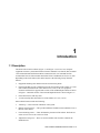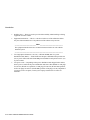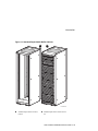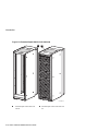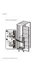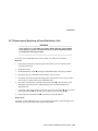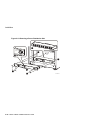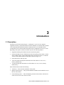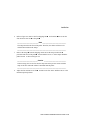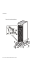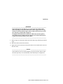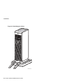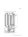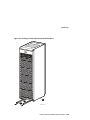
1
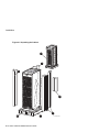
H9A15 Cabinet Installation/Owner's Guide Part Number: EK-H9A15-IN. C01 May 1999 Compaq Computer Corporation Houston, Texas May 1999 COMPAQ COMPUTER CORPORATION SHALL NOT BE LIABLE FOR TECHNICAL OR EDITORIAL ERRORS OR OMISSIONS CONTAINED HEREIN, NOR FOR INCIDENTAL OR CONSEQUENTIAL DAMAGES RESULTING FROM THE FURNISHING, PERFORMANCE, OR USE OF THIS MATERIAL. THIS INFORMATION IS PROVIDED “AS IS” AND COMPAQ COMPUTER CORPORATION DISCLAIMS ANY WARRANTIES, EXPRESS, IMPLIED OR STATUTORY AND EXPRESSLY DISCLAIMS THE IMPLIED WARRANTIES OF MERCHANTABILITY, FITNESS FOR PARTICULAR PURPOSE, GOOD TITLE AND AGAINST INFRINGEMENT. This publication contains information protected by copyright. No part of this publication may be photocopied or reproduced in any form without prior written consent from Compaq Computer Corporation. 1999 Compaq Computer Corporation. All rights reserved. The software described in this guide is furnished under a license agreement or nondisclosure agreement. The software may be used or copied only in accordance with the terms of the agreement. Compaq and the Compaq logo are registered in United States Patent and Trademark Office. AlphaServer is a trademark of Compaq Computer Corporation. Other product names mentioned herein may be trademarks and/or registered trademarks of their respective companies. Table of Contents Preface Overview ..................................................................................................................................vii Intended Audience ....................................................................................................................vii How to Use This Guide .............................................................................................................vii Organization ............................................................................................................................viii Conventions .............................................................................................................................viii Safety Symbol..........................................................................................................................viii Reader's Comments.................................................................................................................... ix Part I H9A15-Bx/Cx/Rx/Sx Cabinets 1 Introduction 1.1 Description........................................................................................................................ 1–1 1.2 Specifications .................................................................................................................... 1–5 2 Installation 2.1 Introduction....................................................................................................................... 2–1 2.2 Tools Required.................................................................................................................. 2–1 2.3 Site Planning ..................................................................................................................... 2–1 2.4 Unpacking......................................................................................................................... 2–3 2.5 Installation Procedures....................................................................................................... 2–9 2.5.1 Removing and Replacing Side Panels With External Screws................................... 2–10 2.5.2 Removing and Replacing Side Panels Without External Screws.............................. 2–12 2.5.3 Removing and Replacing the Front Door Strike Plate ............................................. 2–14 2.5.4 Removing and Replacing the Front Filler Panels..................................................... 2–16 2.5.5 Adjusting the Stabilizer Bars.................................................................................. 2–18 2.5.6 Using the Interlock System .................................................................................... 2–20 iii 2.5.7 Removing and Replacing a Power Distribution Unit............................................... 2–23 Part II H9A15-NA/TA/WA Cabinets 3 Introduction 3.1 Description........................................................................................................................ 3–1 3.2 Specifications.................................................................................................................... 3–5 4 Installation 4.1 Introduction....................................................................................................................... 4–1 4.2 Tools Required.................................................................................................................. 4–1 4.3 Site Planning..................................................................................................................... 4–1 4.4 Unpacking......................................................................................................................... 4–3 4.5 Installation Procedures ...................................................................................................... 4–9 4.5.1 Removing and Replacing the Rear Door................................................................. 4–10 4.5.2 Reversing the Rear Door Swing ............................................................................. 4–12 4.5.3 Removing and Replacing the Front Door................................................................ 4–14 4.5.4 Reversing the Front Door Swing ............................................................................ 4–16 4.5.5 Removing and Replacing the Front Filler Panels .................................................... 4–20 4.5.6 Removing and Replacing the Side Panels ............................................................... 4–22 4.5.7 Adjusting the Stabilizer Bars.................................................................................. 4–24 4.5.8 Using the Interlock System .................................................................................... 4–26 Figures Figure 1-1 Standard Depth H9A15-Bx/Rx Cabinets ................................................................. 1–3 Figure 1-2 Extended Depth H9A15-Cx/Sx Cabinets................................................................. 1–4 Figure 2-1 Unpacking the Cabinet ........................................................................................... 2–4 Figure 2-2 Installing the Ramps............................................................................................... 2–6 Figure 2-3 Deskidding the Cabinet .......................................................................................... 2–8 Figure 2-4 Removing and Replacing Side Panels With External Screws................................. 2–11 Figure 2-5 Removing and Replacing Side Panels Without External Screws ............................ 2–13 Figure 2-6 Removing and Replacing the Front Door Strike Plate............................................ 2–15 Figure 2-7 Removing and Replacing the Metal Front Filler Panels ......................................... 2–17 Figure 2-8 Pulling Out and Adjusting the Stabilizer Bars ....................................................... 2–19 Figure 2-9 The Interlock System ........................................................................................... 2–22 Figure 2-10 Removing a Power Distribution Unit .................................................................. 2–24 Figure 3-1 Standard Depth H9A15-NA/TA/WA Cabinet ......................................................... 3–3 Figure 3-2 H9A15-NA/TA/WA Cabinet with Extender Kit ...................................................... 3–4 Figure 4-1 Unpacking the Cabinet ........................................................................................... 4–4 iv Figure 4-2 Installing the Ramps............................................................................................... 4–6 Figure 4-3 Deskidding the Cabinet .......................................................................................... 4–8 Figure 4-4 Removing and Replacing the Rear Door ............................................................... 4–11 Figure 4-5 Reversing the Rear Door Swing............................................................................ 4–13 Figure 4-6 Removing and Replacing the Front Door .............................................................. 4–15 Figure 4-7 Reversing the Front Door Swing........................................................................... 4–18 Figure 4-8 Completing the Front Door Reversal..................................................................... 4–19 Figure 4-9 Removing and Replacing the Metal Front Filler Panels ......................................... 4–21 Figure 4-10 Removing and Replacing the Side Panels............................................................ 4–23 Figure 4-11 Pulling Out and Adjusting the Stabilizer Bars...................................................... 4–25 Figure 4-12 The Interlock System.......................................................................................... 4–28 v This is some white text. Preface Overview This guide provides the information necessary to install the H9A15 cabinet. This guide does not provide information concerning systems that can be installed in the cabinet. For information concerning systems installed in the cabinet, refer to the respective documentation shipped with the system. Intended Audience The instructions in this guide are for Compaq Customer Service representatives and customer maintenance personnel who are familiar with computer hardware and operating systems. Personnel should be experienced and trained in installing computer and related equipment. How to Use This Guide Read the part of this guide that refers to your cabinet before installing the H9A15 cabinet. As mentioned earlier, for information concerning systems installed in the cabinet, refer to the respective documentation shipped with the system. Before installation, review the warranty. The terms of the warranty agreement with Compaq may require that a qualified Compaq Customer Service representative install the system. Contact your local Compaq representative if you have any questions. vii Organization This guide is organized as follows: Part I Chapter 1, Introduction -- Provides an overview of the H9A15-Bx/Cx/Rx/Sx cabinet features and specifications. Chapter 2, Installation -- Provides site preparation, unpacking, and installation information for the H9A15-Bx/Cx/Rx/Sx cabinet. Part II Chapter 3, Introduction -- Provides an overview of the H9A15-NA/TA/WA cabinet features and specifications. Chapter 4, Installation -- Provides site preparation, unpacking, and installation information for the H9A15-NA/TA/WA cabinet. Conventions The following conventions are used in this guide: Convention Meaning Note A note calls the reader's attention to important information. Caution Cautions provide information to prevent damage to equipment or software. Read these carefully. WARNING A warning contains information essential to the safety of personnel. Safety Symbol The following symbol appears on the power distribution unit. Please review its definition below: This Dangerous Voltage warning symbol indicates a risk of electric shock and indicates hazards from dangerous voltage. viii Reader's Comments Compaq welcomes your comments on this or any other manual. You can send your comments to Compaq in the following ways: • Internet electronic mail: [email protected] • Mail: Compaq Computer Corporation Information Design PKO3-2/21J 129 Parker Street Maynard, MA 01754-2199 For additional information, call 1-800-282-6672. ix This is some white text. Part I H9A15-Bx/Cx/Rx/Sx Cabinets Part I of this manual provides an introduction and installation procedures for the H9A15 cabinets that are listed below. Chapter 1 provides an introduction to these H9A15 cabinets and Chapter 2 provides the installation procedures. Cabinet Description H9A15-BA/BB/BG Standard depth, gray, front trim kit, hinged rear door H9A15-BC/BD/BH Standard depth, gray, hinged front door, hinged rear door H9A15-CA/CB/CG Extended depth, gray, front trim kit, hinged rear door H9A15-CC/CD/CH Extended depth, gray, hinged front door, hinged rear door H9A15-RA/RB/RG Standard depth, blue, front trim kit, hinged rear door H9A15-RC/RD/RH Standard depth, blue, hinged front door, hinged rear door H9A15-SA/SB/SG Extended depth, blue, front trim kit, hinged rear door H9A15-SC/SD/SH Extended depth, blue, hinged front door, hinged rear door This is some white text. 1 Introduction 1.1 Description The H9A15-Bx/Cx/Rx/Sx cabinets (Figure 1-1 and Figure 1-2) are low-cost, computerequipment enclosure systems that meet the Electronic Industries Association (EIA) standard 310C and the International Electrotechnical Commission (IEC) 297 standards and can accommodate fixed or slide-mounted chassis that fit into a standard 48.26-cm (19-in.) rack. Depending on the model ordered, the cabinet may have the following factory installed features: • Equipment mounting rails with the EIA universal rail-hole pattern • Front trim kit that provides a finished look to the front opening of the cabinet, or a front door kit that extends the front of the cabinet out 6.35 cm (2.5 in.) for equipment clearance and front door support. Both versions of the standard depth cabinet are shown in Figure 1-1 and both versions of the extended depth cabinet are shown in Figure 1-2. • Front and rear doors with key locks • A collar assembly that extends the rear of the cabinet 18.75 cm (7.38 in.) Other cabinet features include the following: • Vented top --- This aids in the ventilation of the system. • Hinged vented rear door --- This provides additional ventilation and controlled access to the rear of the cabinet. • Four nonlocking casters --- These facilitate the placement of the cabinet. The front two casters swivel. The rear two casters are fixed. • Adjustable leveling feet --- These are used to stabilize and secure the cabinet at the installation site. H9A15 Cabinet Installation/Owner's Guide 1–1 Introduction • Stabilizer bars --- These are used to provide cabinet stability when installing or sliding equipment out of the cabinet. • Equipment interlock kit --- This is a vertical rod at the rear of the cabinet that allows only one slide-mounted device to be pulled out of the cabinet at any one time. __________________________ Note ____________________________ The equipment installed must have an interlock actuator bracket to work with the interlock system. ___________________________________________________________ • Two single-phase H7600-AA (120 Vac), or H7600-AB/DB (240 Vac) power distribution units (PDUs) --- Each H7600-AA/AB power distribution unit provides ten (10) ac power outlets and each H7600-DB power distribution unit provides twelve (12) ac power outlets. • Two power cords --- Depending on the power distribution units shipped in the cabinet, the two power cords from the power distribution units have either NEMA L5-30P plugs for 120-Vac (H7600-AA) operation, L6-20P plugs for 240-Vac (H7600-AB) operation, or IEC 309 plugs for 240-Vac (H7600-DB) operation. If the plugs are not compatible to your power-source receptacle, contact your Compaq Customer Service office for assistance. 1–2 H9A15 Cabinet Installation/Owner's Guide Introduction Figure 1-1 Standard Depth H9A15-Bx/Rx Cabinets 1 2 SCALE=1/15 LJ-04708-TI0 Standard depth cabinet with front trim kit Standard depth cabinet with front door kit H9A15 Cabinet Installation/Owner's Guide 1–3 Introduction Figure 1-2 Extended Depth H9A15-Cx/Sx Cabinets 1 2 SCALE=1/15 SCALE=90/100 Extended depth cabinet with front trim kit 1–4 H9A15 Cabinet Installation/Owner's Guide LJ-04709-TI0 Extended depth cabinet with front door kit Introduction 1.2 Specifications Specifications for the H9A15 Cabinet are as follows: Physical Height, overall 200 cm (78.7 in.) Width, overall 60.0 cm (23.6 in.) Depth, overall 84.89 cm (33.42 in.) (Standard depth with front trim kit) 91.24 cm (35.92 in.) (Standard depth with front door kit) 103.6 cm (40.8 in.) (Extended depth with front trim kit) 109.95 cm (43.3 in.) (Extended depth with front door kit) Maximum vertical rackmounting space 182.3 cm (71.75 in.) Maximum vertical rackmounting space (with power distribution units installed) 173.4 cm (68.25 in.) Horizontal rack width\ Standard 48.26-cm (19-in.) Weight Standard depth cabinet with front trim kit and two power distribution units 124.74 kg (275 lb) Standard depth cabinet with front trim kit and two power distribution units plus packing material 150.14 kg (331 lb) Fully configured (filled) standard depth cabinet with front trim kit Up to 578.34 kg (1,275 lb) Fully configured (filled) standard depth cabinet with front trim kit plus packing material Up to 603.74 kg (1,331 lb) Standard depth cabinet with front door kit and two power distribution units 141.98 kg (313 lb) Standard depth cabinet with front door kit and two power distribution units plus packing material 167.38 kg (369 lb) Fully configured (filled) standard depth cabinet with front door kit Up to 595.58 kg (1,313 lb) Fully configured (filled) standard depth cabinet with front door kit plus packing material Up to 620.98 kg (1,369 lb) Extended depth cabinet with front trim kit and two power distribution units 137 kg (302 lb) H9A15 Cabinet Installation/Owner's Guide 1–5 Introduction Extended depth cabinet with front trim kit and two power distribution units plus packing material 162.39 kg (358 lb) Fully configured (filled) extended depth cabinet with front trim kit Up to 590.59 kg (1,302 lb) Fully configured (filled) extended depth cabinet with front trim kit plus packing material Up to 616 kg (1,358 lb) Extended depth cabinet with front door kit and two power distribution units 154.22 kg (340 lb) Extended depth cabinet with front door kit and two power distribution units plus packing material 179.63 kg (396 lb) Fully configured (filled) extended depth cabinet with front door kit Up to 607.82 kg (1,340 lb) Fully configured (filled) extended depth cabinet with front door kit plus packing material Up to 633.23 kg (1,396 lb) Casters, swivel, nonlocking: Diameter: Maximum capacity: 7.62 cm (3 in.) 225 kg (500 lb) Casters, fixed, nonlocking: Diameter: Maximum capacity: 7.62 cm (3 in.) 225 kg (500 lb) Enclosure finish Painted Electrical AC input voltage for H7600-AA PDU 100 to 120 Vac, single-phase, 3-wire AC input voltage for H7600-AB PDU 200 to 240 Vac, single-phase, 3-wire AC input voltage for H7600-DB PDU 200 to 240 Vac, single-phase, 3-wire AC load 24 A per H7600-AA PDU 16 A per H7600-AB/DB PDU Input line frequency range 47 to 63 Hz Input power at full load 2.88 kVA per H7600-AA PDU 3.84 kVA per H7600-AB/DB PDU Power cords H7600-AA - Two (2), 120 Vac with L5-30P plugs H7600-AB - Two (2), 240 Vac with L6-20P plugs H7600-DB - Two (2), 240 Vac with IEC 309 plugs 1–6 H9A15 Cabinet Installation/Owner's Guide 2 Installation 2.1 Introduction This chapter provides the following information: • Tools Required (Section 2.2) • Site Planning (Section 2.3) • Unpacking (Section 2.4) • Installation Procedures (Section 2.5) 2.2 Tools Required The tools needed to install the H9A15-Bx/Cx/Rx/Sx cabinet are: • Utility knife • Phillips screwdriver • 9/16-inch open end wrench or adjustable wrench • 8 mm nutdriver 2.3 Site Planning The cabinet requires a space of 60.0 cm (23.6 in.) by 109.95 cm (43.3 in.) maximum, depending on the cabinet model. In addition, the cabinet requires a clearance of 91.44 cm (36.0 in.) at both the front and rear of the cabinet for service. This may be greater depending on the distance that a system may be slid out of the cabinet. H9A15 Cabinet Installation/Owner's Guide 2–1 Installation _______________________ WARNING __________________________ High Leakage Current --- An insulated earthing conductor that is identical in size, insulation material, and thickness to the earthed and unearthed branchcircuit supply conductors (except that it is green with or without one or more yellow stripes) is to be installed as part of the branch circuit that supplies the unit or system. The earthing conductor described is to be connected to earth at the service equipment or, if supplied by a separately derived system, at the supply transformer or motor-generator set. The attachment-plug receptacles in the vicinity of the unit or system are all to be of an earthing type, and the earthing conductors serving these receptacles are to be connected to earth at the service equipment. ___________________________________________________________ _______________________ WARNING __________________________ Use sufficient personnel when unloading the cabinet from the pallet or moving the cabinet to a new location. Depending on the model ordered, the cabinet weighs from 124.74 kg (275 lb) to 154.22 kg (340 lb) empty, and can weigh from 578.34 kg (1,275 lb) up to 607.82 kg (1,340 lb) fully configured. ___________________________________________________________ For site preparation details concerning the system devices installed or the systems to be installed in the cabinet, refer to the documentation for those systems. 2–2 H9A15 Cabinet Installation/Owner's Guide Installation 2.4 Unpacking The cabinet is shipped on a wooden pallet. Proceed as follows to unpack the cabinet: 1. 2. 3. Position the pallet with the cabinet in an area that provides sufficient workspace for unpacking. Ensure that there is sufficient clearance in front of the pallet (marked with arrows) to roll the cabinet down the ramps. Refer to Figure 2-1. Cut and remove the plastic wrapping that secures the corner posts and the carton to the cabinet. The carton contains the two ramps. Remove the corner posts and the carton from the pallet . __________________________ Note _____________________________ In the next step, take care not to damage the cabinet finish when removing the plastic bag. ____________________________________________________________ 4. 5. Remove the plastic bag covering the cabinet. Check the cabinet and the associated equipment for any external damage. Report any damage to Compaq Customer Service or a Compaq sales office and to the responsible freight carrier. __________________________ Note _____________________________ Keep all packing material and receipts in case a damage claim is filed. ____________________________________________________________ H9A15 Cabinet Installation/Owner's Guide 2–3 Installation Figure 2-1 Unpacking the Cabinet 1 2 F 2 3 F 4 2–4 H9A15 Cabinet Installation/Owner's Guide 2 5 LJ-04710-TI0 Installation 6. Refer to Figure 2-2. Remove the four shipping bolts and brackets that secure the four cabinet leveler feet to the pallet . __________________________ Note _____________________________ The ramps attach to the front of the pallet. Therefore, the cabinet will have to be rolled frontwards down the ramps. ____________________________________________________________ 7. Remove the ramps ¡ from the shipping carton and set the ramps in the holes ¢ provided at the front of the pallet . Ensure that the arrows on the ramps match the pallet arrows as shown in Figure 2-2. _________________________ Caution ___________________________ In the next step, the leveler feet must be fully retracted to prevent contact with the ramp or the floor when the cabinet is unloaded from the pallet. ____________________________________________________________ 8. Adjust the four cabinet leveler feet and the leveler feet on the stabilizer bars to the maximum upward position. H9A15 Cabinet Installation/Owner's Guide 2–5 Installation Figure 2-2 Installing the Ramps 7 6 8 3 10 4 1 9 2–6 H9A15 Cabinet Installation/Owner's Guide 2 LJ-06405.AI7 Installation ________________________WARNING __________________________ In the following step, use sufficient personnel to move the cabinet off the pallet. Depending on the model ordered, the cabinet weighs from 124.74 kg (275 lb) to 154.22 kg (340 lb) empty, and can weigh from 578.34 kg (1,275 lb) up to 607.82 kg (1,340 lb) fully configured. If equipment is installed in the cabinet, the cabinet may become top heavy and could accelerate rapidly down the ramps if not restrained. Be prepared to guide and control the motion of the cabinet. ____________________________________________________________ 9. Refer to Figure 2-3 and roll the cabinet down the ramps using sufficient personnel for safety. 10. Wheel the cabinet to the desired location. 11. Adjust the leveler feet downward so that the cabinet is level and the load is removed from the casters. _________________________ Caution ___________________________ Ensure that the leveler feet extend enough to carry the load of the cabinet so that the casters spin freely. If not, the stability of the cabinet may be compromised. ____________________________________________________________ H9A15 Cabinet Installation/Owner's Guide 2–7 Installation Figure 2-3 Deskidding the Cabinet LJ-04712-TI0 2–8 H9A15 Cabinet Installation/Owner's Guide Installation 2.5 Installation Procedures During the installation of the cabinet, one or more of the following procedures may be needed: Removing and Replacing Side Panels With External Screws (Section 2.5.1) Removing and Replacing Side Panels Without External Screws (Section 2.5.2) Removing and Replacing the Front Door Strike Plate (Section 2.5.3) Removing and Replacing the Front Filler Panels (Section 2.5.4) Adjusting the Stabilizer Bars (Section 2.5.5) Using the Interlock System (Section 2.5.6) Removing and Replacing a Power Distribution Unit (Section 2.5.7) H9A15 Cabinet Installation/Owner's Guide 2–9 Installation 2.5.1 Removing and Replacing Side Panels With External Screws The side panels on the H9A15 cabinets are removable. Some of the H9A15 cabinets have side panels that are secured with external screws. __________________________ Note ____________________________ If the side panels are removed, replace them before powering up any equipment. ___________________________________________________________ To remove the side panels with external screws, refer to Figure 2-4 and proceed as follows: Removal 1. Remove the six M5 Phillips-head machine screws securing the side panel to the cabinet frame. 2. Grasp both sides of the side panel and lift the side panel away from the cabinet frame. 3. Place the side panel aside and out of the way. Replacement To replace the side panel, reverse the removal procedure, steps 1 through 3. 2–10 H9A15 Cabinet Installation/Owner's Guide Installation Figure 2-4 Removing and Replacing Side Panels With External Screws 1 SCALE=1/15 LJ-04713-TI0 H9A15 Cabinet Installation/Owner's Guide 2–11 Installation 2.5.2 Removing and Replacing Side Panels Witho ut External Screws The side panels on the H9A15 cabinets are removable. Some of the H9A15 cabinets have side panels that are secured without external screws. __________________________ Note ____________________________ If the side panels are removed, replace them before powering up any equipment. ___________________________________________________________ To remove the side panels without external screws, refer to Figure 2-5 and proceed as follows: Removal 1. 2. Gain access to the inside of the cabinet by opening the hinged rear door and front door (if the cabinet has one). Remove the two M5 hex-head screws that secure the side panel metal tabs to the mounting rail inside the cabinet (one toward the front and one toward the rear of the cabinet). 3. Grasp both sides of the side panel and lift it up until the side panel metal tabs clear the cutouts in the cabinet wall and the top lip of the side panel clears the angle bracket along the top edge of the cabinet. 4. Pull the side panel out and away from the cabinet and set it aside. Replacement To replace the side panel, reverse the removal procedure, steps 1 through 4. Ensure that the side panel metal tabs catch on the mounting rail at the bottom of the cutouts in the cabinet wall and the top lip of the side panel catches the angle bracket along the top edge of the cabinet. 2–12 H9A15 Cabinet Installation/Owner's Guide Installation Figure 2-5 Removing and Replacing Side Panels Without External Screws 4 3 2 1 LJ-06397.AI7 H9A15 Cabinet Installation/Owner's Guide 2–13 Installation 2.5.3 Removing and Replacing the Front Door Str ike Plate To remove the front door strike plate, refer to Figure 2-6 and proceed as follows: Removal Remove either the two 8-32 screws and two 8-32 kepnuts or the two M5 machine screws that secure the front door strike plate to the front collar. Replacement To replace the front door strike plate, align the two holes on the front door strike plate with the two holes on the cabinet frame, and secure it in place with either the two 8-32 screws and two 8-32 kepnuts or two M5 machine screws. __________________________ Note ____________________________ The front door strike plate prevents the left-side access door on an AlphaServer 2100 RM series system (when installed in the door latch area of the H9A15 cabinet) from being fully opened, and must be removed to allow access. ___________________________________________________________ 2–14 H9A15 Cabinet Installation/Owner's Guide Installation Figure 2-6 Removing and Replacing the Front Door Strike Plate 2 1 2 LJ-04714-TI0 H9A15 Cabinet Installation/Owner's Guide 2–15 Installation 2.5.4 Removing and Replacing the Front Filler Pa nels The H9A15 cabinet can have metal or plastic front filler panels. To remove a metal front filler panel, refer to Figure 2-7 and proceed as follows: Removal Grasp the metal front filler panel on both sides and then pull straight back away from the cabinet. Replacement To replace a metal front filler panel , align the sockets on the front filler panel (refer to the exploded view) with the appropriate ball studs on the rails and push the panel into place. To remove a plastic front filler panel, proceed as follows: Removal Remove the four 10-32 screws that secure each corner of the front filler panel to the U-nuts on the front rails and pull the front filler panel away from the cabinet. Replacement To replace a plastic front filler panel, align the holes at each corner of the front filler panel with the U-nuts on the cabinet rails and secure the front filler panel with four 10-32 screws. 2–16 H9A15 Cabinet Installation/Owner's Guide Installation Figure 2-7 Removing and Replacing the Metal Front Filler Panels 1 2 3 4 4 3 2 1 LJ-04715-TI0 H9A15 Cabinet Installation/Owner's Guide 2–17 Installation 2.5.5 Adjusting the Stabilizer Bars The stabilizer bars pull straight out from the bottom front of the cabinet as shown in Figure 2-8. When the stabilizer bars are fully extended, adjust the feet at the end of the stabilizer bars until they touch the floor. _______________________ WARNING __________________________ The stabilizer bars must be fully extended before any system is extended out of the cabinet on its slides. ___________________________________________________________ The H9A15 Cabinet can hold various system configurations. The amount of force required to tip or make the cabinet unstable differs with each configuration. 2–18 H9A15 Cabinet Installation/Owner's Guide Installation Figure 2-8 Pulling Out and Adjusting the Stabilizer Bars 2 1 3 LJ-04716-TI0 H9A15 Cabinet Installation/Owner's Guide 2–19 Installation 2.5.6 Using the Interlock System The interlock system (refer to Figure 2-9) helps prevent cabinet instability by allowing only one system at any one time to be pulled out of the cabinet. The interlock system consists of a vertical rod on which are mounted actuator latches for each product installed in the cabinet. These actuator latches engage the interlock actuator bracket on the rear of rackmount systems. When a rackmount system is pulled out of the cabinet, the actuator latches rotate to prevent any other rackmounted system that has an interlock actuator bracket from being pulled out of the cabinet. The expanded view (A) shows the position of the actuator latches when all systems are pushed into the cabinet. The expanded view (B) shows the position of all actuator latches after one system has been pulled out. _______________________ WARNING __________________________ If additional products are installed into the cabinet, actuator latches for those products should be installed to provide a stable environment. ___________________________________________________________ To install actuator latches, proceed as follows: 1. 2. 3. 4. 5. 6. Remove and save the screws securing the bottom mounting bracket to the cabinet . Slide the mounting bracket off the bottom of the vertical rod . Slide the stabilizer bracket and the actuator latch for the new product onto the bottom of the vertical rod in the proper order. Refer to the new product installation documentation for the proper order of the stabilizer bracket and actuator latch. Replace the bottom mounting bracket and install the screws removed in step 1 but do not tighten them. Position the stabilizer bracket so that the bottom hole in the stabilizer bracket aligns with the EIA rail hole adjacent to the bottom of the installed product. This may require the loosening and sliding of other latches and stabilizer brackets to accommodate the new configuration. Place the nut plate behind the EIA rail and install and tighten the screws provided to secure the stabilizer bracket. 7. Position the new actuator latch to properly engage the product, and tighten the set screws to secure the latch. 8. Now tighten the screws to secure the bottom mounting bracket . 2–20 H9A15 Cabinet Installation/Owner's Guide Installation __________________________ Note _____________________________ Some systems may not be compatible because the interlock actuator bracket may not engage properly. In these cases, do not install the interlock actuator bracket on those systems. ____________________________________________________________ ________________________WARNING __________________________ If a system is installed without an interlock actuator bracket or the vertical rod in the cabinet does not engage properly with the system interlock actuator bracket, it is the customer's responsibility to provide a stable cabinet. ____________________________________________________________ H9A15 Cabinet Installation/Owner's Guide 2–21 Installation Figure 2-9 The Interlock System A 5 6 3 B 2 1 MAIN POWE 1 R MAIN POWE 1 R 1 0 0 4 LJ-04717-TI0 2–22 H9A15 Cabinet Installation/Owner's Guide Installation 2.5.7 Removing and Replacing a Power Distributi on Unit ________________________WARNING __________________________ There can be two or more PDUs per cabinet. Ensure that all systems installed in the cabinet are turned off as described in the system documentation before performing the following procedure. ____________________________________________________________ To remove a power distribution unit, refer to Figure 2-10 and proceed as follows: Removal 1. If the cabinet contains an operating system, turn off the system as described in the system documentation. 2. Open the rear door. 3. Set the Main Power switch on all power distribution units to the off (O) position. 4. Disconnect the power distribution units from the ac power source. 5. If required, remove the bottom front filler panel (refer to Section 2.5.4). This provides access to the ac outlets on the power distribution units. 6. 7. 8. Note and record the power cord connections to the outlets at the rear of the power distribution unit being removed. Then unplug the power cords from that power distribution unit. At the rear of the cabinet, remove the four (4) 10-32 truss-head screws that secure the power distribution unit to the rear rails (via the four (4) 10-32 clip nuts ). Pull out the power distribution unit and remove it from the cabinet. Replacement To replace a power distribution unit, reverse the removal procedure, steps 2 through 8, then follow the power-on procedure in the system documentation. H9A15 Cabinet Installation/Owner's Guide 2–23 Installation Figure 2-10 Removing a Power Distribution Unit Not for external loads J1 J2 J3 J4 Ne s’appliqu pas a l’alimentation externe. J5 2 M A IN POWE R 4 1 4 MAI N POW ER MAI N POW ER 5 3 3 2–24 H9A15 Cabinet Installation/Owner's Guide LJ-04288-TI0 Part II H9A15-NA/TA/WA Cabinets Part II of this manual provides an introduction and installation procedures for the H9A15 cabinet models that are listed below. Chapter 3 provides an introduction to these H9A15 cabinets and Chapter 4 provides the installation procedures. Cabinet Description H9A15-NA Gray standard depth base cabinet H9A15-TA Blue standard depth base cabinet H9A15-WA White standard depth base cabinet One of the front dress treatment kits listed below is required for the base cabinet. Front Dress Kit Description H9C15-NF Gray front door kit H9C15-NT Gray front trim kit H9C15-TF Blue front door kit H9C15-TT Blue front trim kit H9C15-WF White front door kit H9C15-WT White front trim kit This is some white text. 3 Introduction 3.1 Description The H9A15-NA/TA/WA cabinet (Figure 3-1 and Figure 3-2) are low-cost, computerequipment enclosure systems that meet the Electronic Industries Association (EIA) standard 310C and the International Electrotechnical Commission (IEC) 297 standards and can accommodate fixed or slide-mounted chassis that fit into a standard 48.26-cm (19-in.) rack. Depending on the options ordered, the cabinet may have the following features: • Equipment mounting rails with the EIA universal rail-hole pattern • Front trim kit that provides a finished look to the front opening of the cabinet or a front door kit. Both versions of the standard depth cabinet are shown in Figure 3-1 and both versions of the cabinet with the extender kit are shown in Figure 3-2. • Front and rear doors with key locks • A door and collar assembly that extends the front of the cabinet 6.35 cm (2.5 in.) (Factory installed only) • A collar assembly that extends the rear of the cabinet 18.75 cm (7.38 in.) (Factory installed only) Other cabinet features include the following: • Vented top --- This aids in the ventilation of the system. • Hinged vented rear door --- This provides additional ventilation and controlled access to the rear of the cabinet. • Four nonlocking casters --- These facilitate the placement of the cabinet. The front two casters swivel. The rear two casters are fixed. H9A15 Cabinet Installation/Owner's Guide 3–1 Introduction • Adjustable leveling feet --- These are used to stabilize and secure the cabinet at the installation site. • Stabilizer bars --- These are used to provide cabinet stability when installing or sliding equipment out of the cabinet. • Equipment interlock kit --- This is a vertical rod at the rear of the cabinet that allows only one slide-mounted device to be pulled out of the cabinet at any one time. __________________________ Note ____________________________ The equipment installed must have an interlock actuator bracket to work with the interlock system. ___________________________________________________________ 3–2 H9A15 Cabinet Installation/Owner's Guide Introduction Figure 3-1 Standard Depth H9A15-NA/TA/WA Cabinet 1 2 SCALE=1/15 LJ-06351.AI7 Standard depth cabinet with optional front trim kit Standard depth cabinet with optional front door kit and optional front and rear extender kit H9A15 Cabinet Installation/Owner's Guide 3–3 Introduction Figure 3-2 H9A15-NA/TA/WA Cabinet with Extender Kit 1 2 SCALE=1/15 SCALE=90/100 Cabinet with optional extender kit and optional front trim kit 3–4 H9A15 Cabinet Installation/Owner's Guide LJ-06352.AI7 Cabinet with optional extender kit and optional front door kit Introduction 3.2 Specifications Specifications for the H9A15-NA/TA/WA cabinet are as follows: Physical Height, overall 200 cm (78.7 in.) Width, overall 60.0 cm (23.6 in.) Depth, overall 91.6 cm (36.1 in.) (Standard depth with front trim kit or front door kit) 97.9 cm (38.6 in.) (Extender kit with front door kit) Maximum vertical rackmounting space 182.3 cm (71.75 in.) (41U) Maximum vertical rackmounting space (with power distribution units installed) 173.4 cm (68.25 in.) (39U) Horizontal rack width\ Standard 48.26-cm (19-in.) Weight Fully configured (filled) standard depth cabinet with front trim kit Up to 578.34 kg (1,275 lb) Fully configured (filled) standard depth cabinet with front trim kit plus packing material Up to 603.74 kg (1,331 lb) Fully configured (filled) standard depth cabinet with front door kit Up to 595.58 kg (1,313 lb) Fully configured (filled) standard depth cabinet with front door kit plus packing material Up to 620.98 kg (1,369 lb) Fully configured (filled) cabinet with extender kit and front trim kit Up to 590.59 kg (1,302 lb) Fully configured (filled) cabinet with extender kit and front trim kit plus packing material Up to 616 kg (1,358 lb) Fully configured (filled) cabinet with extender kit and front door kit Up to 607.82 kg (1,340 lb) Fully configured (filled) cabinet with extender kit and front door kit plus packing material Up to 633.23 kg (1,396 lb) Casters, swivel, nonlocking: Diameter: Maximum capacity: 7.62 cm (3 in.) 318 kg (700 lb) Casters, fixed, nonlocking: Diameter: Maximum capacity: 7.62 cm (3 in.) 318 kg (700 lb) Enclosure finish Painted H9A15 Cabinet Installation/Owner's Guide 3–5 This is some white text. 4 Installation 4.1 Introduction This chapter provides the following information: • Tools Required (Section 4.2) • Site Planning (Section 4.3) • Unpacking (Section 4.4) • Installation Procedures (Section 4.5) 4.2 Tools Required The tools needed to install the H9A15-NA/TA/WA cabinet are: • Utility knife • Phillips screwdriver • 9/16-inch open end wrench or adjustable wrench • 8 mm nutdriver 4.3 Site Planning The cabinet requires a space of 60.0 cm (23.6 in.) by 91.6 cm (36.1 in.) maximum, depending on the cabinet model. In addition, the cabinet requires a clearance of 91.44 cm (36.0 in.) at both the front and rear of the cabinet for service. This may be greater depending on the distance that a system may be slid out of the cabinet. H9A15 Cabinet Installation/Owner's Guide 4–1 Installation _______________________ WARNING __________________________ Use sufficient personnel when unloading the cabinet from the pallet or moving the cabinet to a new location. Depending on the model ordered, the cabinet weighs from 124.74 kg (275 lb) to 154.22 kg (340 lb) empty, and can weigh from 578.34 kg (1,275 lb) up to 607.82 kg (1,340 lb) fully configured. ___________________________________________________________ For site preparation details concerning the system devices installed or the systems to be installed in the cabinet, refer to the documentation for those systems. 4–2 H9A15 Cabinet Installation/Owner's Guide Installation 4.4 Unpacking The cabinet is shipped on a wooden pallet. Proceed as follows to unpack the cabinet: 1. 2. 3. Position the pallet with the cabinet in an area that provides sufficient workspace for unpacking. Ensure that there is sufficient clearance in front of the pallet (marked with arrows) to roll the cabinet down the ramps. Refer to Figure 4-1. Cut and remove the plastic wrapping that secures the corner posts and the carton to the cabinet. The carton contains the two ramps. Remove the corner posts and the carton from the pallet . __________________________ Note _____________________________ In the next step, take care not to damage the cabinet finish when removing the plastic bag. ____________________________________________________________ 4. 5. Remove the plastic bag covering the cabinet. Check the cabinet and the associated equipment for any external damage. Report any damage to Compaq Customer Service or a Compaq sales office and to the responsible freight carrier. __________________________ Note _____________________________ Keep all packing material and receipts in case a damage claim is filed. ____________________________________________________________ H9A15 Cabinet Installation/Owner's Guide 4–3 Installation Figure 4-1 Unpacking the Cabinet 1 2 F 2 3 F 4 4–4 H9A15 Cabinet Installation/Owner's Guide 2 5 LJ-06353.AI7 Installation 6. Refer to Figure 4-2. Remove the four shipping bolts and brackets that secure the four cabinet leveler feet to the pallet . __________________________ Note _____________________________ The ramps attach to the front of the pallet. Therefore, the cabinet will have to be rolled frontwards down the ramps. ____________________________________________________________ 7. Remove the ramps ¡ from the shipping carton and set the ramps in the holes ¢ provided at the front of the pallet . Ensure that the arrows on the ramps match the pallet arrows as shown in Figure 4-2. _________________________ Caution ___________________________ In the next step, the leveler feet must be fully retracted to prevent contact with the ramp or the floor when the cabinet is unloaded from the pallet. ____________________________________________________________ 8. Adjust the four cabinet leveler feet and the leveler feet on the stabilizer bars to the maximum upward position. H9A15 Cabinet Installation/Owner's Guide 4–5 Installation Figure 4-2 Installing the Ramps 7 6 8 3 10 4 1 9 4–6 H9A15 Cabinet Installation/Owner's Guide 2 LJ-06354.AI7 Installation ________________________WARNING __________________________ In the following step, use sufficient personnel to move the cabinet off the pallet. Depending on the model ordered, the cabinet weighs from 124.74 kg (275 lb) to 154.22 kg (340 lb) empty, and can weigh from 578.34 kg (1,275 lb) up to 607.82 kg (1,340 lb) fully configured. If equipment is installed in the cabinet, the cabinet may become top heavy and could accelerate rapidly down the ramps if not restrained. Be prepared to guide and control the motion of the cabinet. ____________________________________________________________ 9. Refer to Figure 4-3 and roll the cabinet down the ramps using sufficient personnel for safety. 10. Wheel the cabinet to the desired location. 11. Adjust the leveler feet downward so that the cabinet is level and the load is removed from the casters. _________________________ Caution ___________________________ Ensure that the leveler feet extend enough to carry the load of the cabinet so that the casters spin freely. If not, the stability of the cabinet may be compromised. ____________________________________________________________ H9A15 Cabinet Installation/Owner's Guide 4–7 Installation Figure 4-3 Deskidding the Cabinet LJ-06355.AI7 4–8 H9A15 Cabinet Installation/Owner's Guide Installation 4.5 Installation Procedures During the installation of the cabinet, one or more of the following procedures may be needed: • Removing and Replacing the Rear Door (Section 4.5.1) • Reversing the Rear Door Swing (Section 4.5.2) • Removing and Replacing the Front Door (Section 4.5.3) • Reversing the Front Door Swing (Section 4.5.4) • Removing and Replacing the Front Filler Panels (Section 4.5.5) • Removing and Replacing the Side Panels (Section 4.5.6) • Adjusting the Stabilizer Bar (Section 4.5.7) • Using the Interlock System (Section 4.5.8) The tools needed to perform the above procedures are: • Phillips screwdriver • 8 mm hex-head nutdriver H9A15 Cabinet Installation/Owner's Guide 4–9 Installation 4.5.1 Removing and Replacing the Rear Door The rear door provides access into the rear of the cabinet. To remove the rear door, refer to Figure 4-4 and proceed as follows: Removal 1. 2. 3. 4. Open the door and loosen the two M5 hex-head screws that secure the top rear trim piece to the top of the cabinet. Slide the top rear trim piece toward the rear of the cabinet until the screw heads are aligned with the keyhole and lift the top rear trim piece off of the cabinet. While holding the rear door in place, remove the three M5 screws that secure the top pivot bracket to the top right of the cabinet and remove the bracket. Lift the rear door off of the bottom pivot pin located at the bottom right of the cabinet and place the rear door aside and out of the way. Replacement To replace the rear door, reverse the removal procedure, steps 1 through 4. When replacing the rear door, adjust the position of the top pivot bracket to ensure that the door is square with the cabinet opening. Once the door is square, tighten the top pivot bracket mounting screws. 4–10 H9A15 Cabinet Installation/Owner's Guide Installation Figure 4-4 Removing and Replacing the Rear Door 6 2 3 1 5 4 7 6 LJ-06394.AI7 H9A15 Cabinet Installation/Owner's Guide 4–11 Installation 4.5.2 Reversing the Rear Door Swing The rear door on the H9A15 cabinet comes form the factory hinged on the right side of the cabinet as viewed from the rear of the cabinet. The door swing can be reversed so that the rear door is hinged on the left side of the cabinet as viewed from the rear of the cabinet. To reverse the rear door swing, refer to Figure 4-5 and proceed as follows: 1. Remove the rear door (see Section 4.5.1). 2. Remove the bottom pivot pin and plastic washer from the bottom pivot bracket located at the bottom right of the cabinet (see Figure 4-4 ). 3. 4. 5. Install the bottom pivot pin and washer in the bottom pivot bracket located at the bottom left of the cabinet (see Figure 4-5). Remove the wear pad (see Figure 4-5) from the rear hole of the bottom pivot bracket located at the bottom left of the cabinet and move it to the rear hole of the bottom pivot bracket located at the bottom right of the cabinet. Remove the two M5 screws that secure the strike plate to the left side of the cabinet. 6. Install the strike plate on the right side of the cabinet using the two M5 screws. Ensure that the lip on the strike plate is pointing to the left. 7. Remove the top pivot pin from the right front hole on the top pivot bracket (see Figure 4-4) and install the pivot pin into the left front hole on the top pivot bracket (see Figure 4-5). 8. 9. Turn the rear door upside down so that the locking mechanism ¢ is on the right. Set the rear door on the bottom pivot pin located at the bottom left of the cabinet. 10. Insert the top pivot pin on the top pivot bracket ¡ into the hole at the top left corner of the door and, while holding the door in place, adjust the position of the top pivot bracket to ensure that the door is square with the cabinet opening. Once the door is square, secure the top pivot bracket to the top left of the cabinet by tightening the three M5 screws . 11. Adjust the strike plate so that the door does not rattle and the lock properly engages the strike plate. 12. Reinstall the top rear trim piece on the top rear of the cabinet. 13. Reverse the handle on the door latch by unscrewing the lock and turning the handle upside down so that the handle is toward the bottom of the door. 4–12 H9A15 Cabinet Installation/Owner's Guide Installation Figure 4-5 Reversing the Rear Door Swing 2 1 7 4 3 10 1 9 5 8 6 2 LJ-06395.AI7 H9A15 Cabinet Installation/Owner's Guide 4–13 Installation 4.5.3 Removing and Replacing the Front Door The front door provides access into the front of the cabinet. To remove the front door, refer to Figure 4-6 and proceed as follows: Removal 1. Open the door and loosen the two M5 hex-head screws that secure the top front trim piece to the top of the cabinet. 2. Slide the top front trim piece up and off of the cabinet. 3. While holding the front door in place, remove the two M5 screws that secure the top pivot bracket to the top left of the cabinet and remove the bracket. 4. Lift the front door off of the bottom pivot pin located at the bottom left of the cabinet and place the front door aside and out of the way. Replacement To replace the front door, reverse steps 1 through 4 of the removal procedure. When replacing the front door, adjust the position of the top pivot bracket to ensure that the door is square with the cabinet opening. Once the door is square, tighten the top pivot bracket mounting screws. 4–14 H9A15 Cabinet Installation/Owner's Guide Installation Figure 4-6 Removing and Replacing the Front Door 1 2 3 4 3 6 5 LJ-06398.AI7 H9A15 Cabinet Installation/Owner's Guide 4–15 Installation 4.5.4 Reversing the Front Door Swing The front door on the H9A15 cabinet comes from the factory hinged on the left side of the cabinet as viewed from the front of the cabinet. The door swing can be reversed so that the front door is hinged on the right side of the cabinet as viewed from the front of the cabinet. To reverse the rear door swing, refer to Figure 4-7and Figure 4-8 and proceed as follows: 1. Remove the front door (see Section 4.5.3) and set it aside with the inside of the door facing outward. 2. Remove the rubber bumpers from top and bottom left corners of the door and move them to the top and bottom right corners of the door. 3. Remove the bottom pivot pin and plastic washer from the bottom pivot bracket located at the bottom left of the cabinet (see Figure 4-6 ). 4. 5. Install the bottom pivot pin and washer in the bottom pivot bracket located at the bottom right of the cabinet (see Figure 4-7). Remove the door alignment ramp from the bottom right of the cabinet and install it at the bottom left of the cabinet. 6. Remove the two M5 screws that secure the strike plate to the right side of the cabinet. 7. Install the strike plate on the left side of the cabinet using the two M5 screws. 8. Remove the top pivot pin from the left front hole on the top pivot bracket (see Figure 4-6) and install the pivot pin into the right front hole on the top pivot bracket (see Figure 4-8 ). 9. While facing the inside of the front door, remove the four M5 nuts that secure the blank panel to the right front of the door and remove the blank panel (see Figure 4-7). 10. While facing the inside of the front door, remove the four M5 nuts that secure the latch and lock assembly panel ¡ to the left front of the door and remove the latch and lock assembly panel (see Figure 4-7). Note: Some cabinets may have a lock guard over the latch and lock assembly panel that is also secured by the four M5 nuts. 11. Remove the nut ¢ that secures the lock mechanism to the top part of the latch and lock assembly panel. 12. Move the lock mechanism to the bottom part of the latch and lock assembly panel and secure it with the nut ¢ removed in step 11. 13. Turn the latch and lock assembly panel upside down so that the latch is toward the right side of the door (as viewed from facing the inside of the front door) and the lock mechanism is at the top. 4–16 H9A15 Cabinet Installation/Owner's Guide Installation 14. While facing the inside of the front door, secure the latch and lock assembly panel to the right front of the door using four M5 nuts (see Figure 4-8). Note: If a lock guard was installed over the latch and lock assembly panel, it must also be secured by these four M5 nuts. 15. While facing the inside of the front door, secure the blank panel to the left front of the door using four M5 nuts . 16. Set the front door on the bottom pivot pin located at the bottom right of the cabinet. 17. Insert the top pivot pin on the top pivot bracket into the hole at the top right corner of the door and, while holding the door in place, adjust the position of the top pivot bracket to ensure that the door is square with the cabinet opening. Once the door is square, secure the top pivot bracket to the top right of the cabinet by tightening the two M5 screws . 18. Adjust the strike plate so that the door does not rattle and the lock properly engages the strike plate. 19. Reinstall the top front trim piece on the top front of the cabinet and tighten the two M5 hex-head screws (see Figure 4-8). H9A15 Cabinet Installation/Owner's Guide 4–17 Installation Figure 4-7 Reversing the Front Door Swing 2 1 3 4 5 10 9 7 8 6 1 LJ-06399.AI7 4–18 H9A15 Cabinet Installation/Owner's Guide Installation Figure 4-8 Completing the Front Door Reversal 2 4 5 3 6 7 9 10 8 2 1 LJ-06400.AI7 H9A15 Cabinet Installation/Owner's Guide 4–19 Installation 4.5.5 Removing and Replacing the Front Filler Pa nels The H9A15 cabinet can have metal or plastic front filler panels. To remove a metal front filler panel, refer to Figure 4-9 and proceed as follows: Removal Grasp the metal front filler panel on both sides and then pull straight back away from the cabinet. Replacement To replace a metal front filler panel , align the sockets on the front filler panel (refer to the exploded view) with the appropriate ball studs on the rails and push the panel into place. To remove a plastic front filler panel, proceed as follows: Removal Remove the four 10-32 screws that secure each corner of the front filler panel to the U-nuts on the front rails and pull the front filler panel away from the cabinet. Replacement To replace a plastic front filler panel, align the holes at each corner of the front filler panel with the U-nuts on the cabinet rails and secure the front filler panel with four 10-32 screws. 4–20 H9A15 Cabinet Installation/Owner's Guide Installation Figure 4-9 Removing and Replacing the Metal Front Filler Panels 1 2 3 4 4 3 2 1 LJ-06356.AI7 H9A15 Cabinet Installation/Owner's Guide 4–21 Installation 4.5.6 Removing and Replacing the Side Panels The H9A15 cabinet has removable side panels that can be swapped from one side of the cabinet to the other. To remove a side panel, refer to Figure 4-10 and proceed as follows: Removal 1. Gain access to the inside of the cabinet by opening the rear door and the front door (if the cabinet has one). 2. If the cabinet has a front trim kit or a non-extended front door kit, remove the two Phillips-head screws that secure bottom front trim cover . 3. Remove the two M5 screws that secure the bottom front and rear corners of the side panel to the cabinet. These screws are located underneath the metal lip that is parallel to the floor at the bottom front and bottom rear of the cabinet. 4. Grasp both sides of the side panel and lift it up until the side panel metal tabs clear the cutouts in the cabinet wall and the top lip of the side panel clears the angle bracket along the top edge of the cabinet. 5. Pull the side panel out and away from the cabinet and set it aside. Replacement To replace the side panel, reverse the removal procedure, steps 1 through 5. Ensure that the side panel metal tabs catch on the mounting rail at the bottom of the cutouts in the cabinet wall and the top lip of the side panel catches the angle bracket along the top edge of the cabinet. 4–22 H9A15 Cabinet Installation/Owner's Guide Installation Figure 4-10 Removing and Replacing the Side Panels 4 5 5 4 2 3 1 2 3 LJ-06396.AI7 H9A15 Cabinet Installation/Owner's Guide 4–23 Installation 4.5.7 Adjusting the Stabilizer Bars The stabilizer bars pull straight out from the bottom front of the cabinet as shown in Figure 4-11. When the stabilizer bars are fully extended, adjust the feet at the end of the stabilizer bars until they touch the floor. _______________________ WARNING __________________________ The stabilizer bars must be fully extended before any system is extended out of the cabinet on its slides. ___________________________________________________________ The H9A15 cabinet can hold several system configurations. The amount of force required to tip or make the cabinet unstable differs with each configuration. 4–24 H9A15 Cabinet Installation/Owner's Guide Installation Figure 4-11 Pulling Out and Adjusting the Stabilizer Bars 2 1 3 LJ-06350.AI7 H9A15 Cabinet Installation/Owner's Guide 4–25 Installation 4.5.8 Using the Interlock System The interlock system (refer to Figure 4-12) helps prevent cabinet instability by allowing only one system at any one time to be pulled out of the cabinet. The interlock system consists of a vertical rod on which are mounted actuator latches for each product installed in the cabinet. These actuator latches engage the interlock actuator bracket on the rear of rackmount systems. When a rackmount system is pulled out of the cabinet, the actuator latches rotate to prevent any other rackmounted system that has an interlock actuator bracket from being pulled out of the cabinet. The expanded view (A) shows the position of the actuator latches when all systems are pushed into the cabinet. The expanded view (B) shows the position of all actuator latches after one system has been pulled out. If additional products are installed into the cabinet, actuator latches for those products should be installed. To install actuator latches, proceed as follows: 1. 2. 3. 4. 5. 6. 7. Remove the screws securing the bottom mounting bracket to the cabinet . Slide the mounting bracket off the bottom of the vertical rod . Slide the stabilizer bracket for the new product onto the bottom of the vertical rod. Slide the actuator latch for the new product onto the bottom of the vertical rod. Replace the bottom mounting bracket and install the screws removed in step 1 but do not tighten them. Position the stabilizer bracket so that the bottom hole in the stabilizer bracket aligns with the EIA rail hole adjacent to the bottom of the installed product. This may require the loosening and sliding of other latches and stabilizer brackets to accommodate the new configuration. Place the nut plate behind the EIA rail and install and tighten the screws provided to secure the stabilizer bracket. 8. Position the new actuator latch to properly engage the product, and tighten the set screws to secure the latch. 9. Now tighten the screws to secure the bottom mounting bracket . 4–26 H9A15 Cabinet Installation/Owner's Guide Installation __________________________ Note _____________________________ Some systems may not be compatible because the interlock actuator bracket may not engage properly. In these cases, do not install the interlock actuator bracket on those systems. ____________________________________________________________ ________________________WARNING __________________________ If a system is installed without an interlock actuator bracket or the vertical rod in the cabinet does not engage properly with the system interlock actuator bracket, it is the customer's responsibility to provide a stable cabinet. ____________________________________________________________ H9A15 Cabinet Installation/Owner's Guide 4–27 Installation Figure 4-12 The Interlock System A 5 6 3 B 2 1 MAIN POWE 1 R MAIN POWE 1 R 1 0 0 4 LJ-06358.AI7 4–28 H9A15 Cabinet Installation/Owner's Guide