1
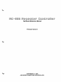
~(b=®S5(ID ~@~~@[t@rr (b©[(i)[trr@OO~rr Hardware Reference Manual
Firmware Version 3
COPYRIGHT © 1987 ADVANCED COMPUTER CONTROLS, INC. Got a question? Be sure and check the manual supplement,
"Most Often Asked Questions and Answers".
Touch-Tone is a registered trademark of American Telephone and Telegraph Company. Copyright (c) 1987 Advanced Computer Controls, Inc. All rights reserved Printed in U.S.A. Specifications subject to change without notice RC-850 Controller Software Copyright (c) 1983, 1987 ACC RC-850 Controller Command Codes Copyright (c) 1983, 1987 ACC 8/87 Rev 3
~
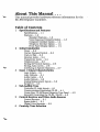
About This Manual ...
This manual provides hardware reference information for the
RC-850 Repeater Controller.
Table of Contents 1
Specifications and Features Specifications ... 1-1 Features ... 1-2 Standard Features ... 1-2 Voice Response Telemetry Option ... 1-3 Computer Interface Option ... 1-4 Telephone Interface Option ... 1-4 Front Panel Display Option ... 1-4 2
Initial Installation
Power ... 2-2 Carrier-Operated Switch ... 2-3 Push-to-Talk ... 2-3 Receiver AudiO ... 2-4 Transmitter Audio ... 2-4 Telephone Line ... 2-5 Setting DIP Switch Options ... 2-5 Setting Audio Levels ... 2-6 Interfacing to Specific Repeaters ... 2-7 3
Input I Output Characteristics Logic Inputs ... 3-1 Logic Outputs ... 3-1 Audio Inputs ... 3-2 Audio Outputs ... 3-2 Analog Measurement Inputs ... 3-2 Serial I/O ... 3-3 4
Sub-Audible Tone
Controller PL Logic Inputs ... 4-1 Communications Specialists TS-32 ... 4-1 Comm Spec TP-38 Shared Repeater Tone Panel ... 4-2 Remotely Controlling the TS-32 / SS-32 ... 4-3 5
Control Receiver and Other Audio Sources
Control Receiver ... 5-1 Spare Audio 1 ... 5-1 Digital Voice Recorder ... 5-2 6 Courtesy Tone Selection
7
Telephone Interface Telephone Interface Board ... 7-1 Second Local Phone Line ... 7-1 Remote Phone Lines ... 7-2 Sharing the Phone Line ... 7-3 Using An Existing Coupler ... 7-4 Dial Tone Detector ... 7-4 8
Remote Bases and Links Receive Audio ... 8-1 Link Transmit Audio ... 8-1 COS and PIT ... 8-2 Frequency Control ... 8-2 Interface to ICOM IC-22U Synthesizer ... 8-4 Driving Two Shift Register Chains ... 8-4 Controlling an HF Remote Base ... 8-5 Alarms 10 General Purpose Remote Control 9
Remote Control Logic Outputs ... 10-1 11 Remote Metering S-Meter ... 11-1 Quieting ... 11-3 Temperature ... 11-3 Voltage ... 11-6 Current ... 11-7 Power ... 11-8 Everything You Need to Know About Op Amps ... 11-11 12 Principles of Operation Main Controller Board ... 12-2 Telephone Interface Board ... 12-5 Front Panel Display Board ... 12-6 VOice Response Telemetry Board ... 12-7 Computer Interface Board ... 12-8 13 Troubleshooting Maintenance & Servicing ... 13-1 General Checklist ... 13-2 RF Interference ... 13-3 Appendix I
Appendix II
Appendix III
Appendix IV
Appendix V
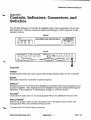
Controls, Indicators, Connectors, DIP Switches
Interface to Specific Repeaters
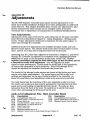
Adjustments
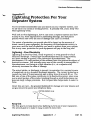
Lightning Protection
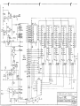
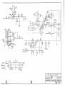
Schematics and Parts Placement Diagrams
Hardware Reference Manual
Chapter 1
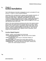
Specifications and Features
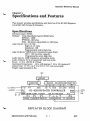
This chapter provides specifications and features of the RC-S50 Repeater
Controller with Version 3 Firmware.
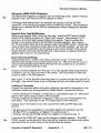
Specifications
Microprocessor: SOCS5
Memory: Total expandable beyond 3S4K bytes
EPROM -136K
E2PROM - SK bytes
RAM - SK bytes, expandable to 16K bytes
Logic Inputs: Low <.S volts
High 2.4-15 volts
Impedance 10K
Programmable active high/low
Logic Outputs: VMOS power transistors (open drain)
60V / 100 rnA drive capacity
Programmable active high/low
Audio Inputs: lOOK impedance, adjustable levels
Audio Outputs: 5V p-p transmitter and link audio
Power: 11.5 to 15V DC @ 175mA
Operating Temperature: -15 to +55 degrees C (5 to 131 degrees F)
Cabinet size: 17" W x 14.5" D x 2.5" H, 19" rack mountable
Weight: ApprOximately 4lbs.
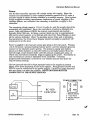
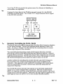
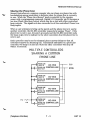
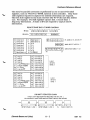
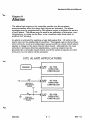
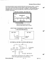
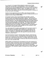
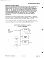
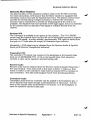
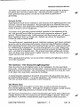
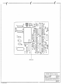
12 V SUPPLy---t +12V
BATTERY PTT
AUDIO
COS
PL
BAT
RC-850 REPEATER
......---tAGND
DGND METERS ALARM CT SELECT AUD 10
COS AUD 10
CONTROLLER
RS-232
I---+- PHONE
1---+-2nd
LINE
REPEATER BLOCK DIAGRAM
(Specifications and Features)
1- 1
8/87
Hardware Reference Manual
Features
Standard Features (on main controller board)
o Main controller board is a complete standalone repeater controller
o Remotely programmable with Touch-Tone commands:
• Messages - over 200 (ID's, tails, mailbox, etc.).
May include CW, paging tones, DTMF tones, external devices, synthesized
speech (w/VRf option), and Digital Voice Recorder tracks (w/DVR)
• Morse code parameters: Speed - 5-35 WPM, Pitch - DC-3000 Hz, Level - 4 steps • Control Op and user command codes (30 prefIX groups, up to 7 digits each)
• Courtesy tone parameters (13 sets - pitch, durations, spacings fully programmable) • Timers - 27 sets, 0-30 minute with 1 second resolution
• Autodialer numbers (250)
.
• Telephone exchange tables
• Pager memories
• Remote base frequency memories
• Non-volatile E2PROM storage (no batteries)
o Autopatch / Autodial (requires Telephone Interface Option for local line)
• Supports up to two local phone lines, three remote phone lines (3 total)
• Store/forward, DTMF or rotary (2 speeds each)
• Optional phone number readback
• User Loadable Autodial - 240 numbers (50 numbers hold up to 35 digits)
• Emergency Autodial (10 numbers) with message readback
• Antidialer - traps 10 numbers, permits wildcards and globals for blocks of numbers • Toll restrict -leading 1/0 and digit count: or exchange tables for telephone exchanges in 2 area codes, 3 permitted area codes • Full or half duplex patch
• Cover tone for semi-private patches
• Activity timer with warning warble
• Autodial storage of credit card / MCI / Sprint access codes
o Reverse patch - general or directed to 100 stored user call signs
o Paging - two-tone, 5/6 tone, DTMF, CTCSS, HSC display, GSC digital,
commandable or may be included in any programmable messages
o Electronic Mailbox:
• User-to-user mail
• System generated mail: system generated mail- unanswered reverse patch and alarms • Addressed by user call sign slot, 100 user call sign storage
• 10 "canned" messages; digits may be appended to messages, Le., phone numbers o Remote bases and links
• Up to 4 transceivers
• Commandable frequency and offset of 2 transceivers
• Remote base frequency memories with names
• Cross-linking of the transceivers
• Command entry from the remotes and links
(Specifications and Features)
1- 2
8/87
Hardware Reference Manual
o 11 access and control modes
• PL for access, user level, or Control Op level command
• Main and "user level only" PL inputs
• Touch-Tone access mode with programmable timeout
• Individual user access codes for 800 users
• Attributes for further custom tailoring
o 10 "Macro Sets for easy Control Operator selection of predefined
repeater setup parameters
o General purpose remote control
• Logic outputs - 6 expandable to 64
o Audio delay line (75 ms) to mute squelch tails and fully mute Touch-Tone
o Courtesy tone
• 13 sets to convey information
• Selectable by Control Op or logic inputs
• Programmable pitch, delay, and spacing of 3 segments per tone set
o Low distortion computer synthesized tone generation, single and dual
frequency, programmable to 1 Hz resolution, 4 levels
o Noise and kerchunker filtering
o Control receiver provisions
o Fully integrated CMOS 16 digit DTMF decoder
o Intelligent ID algorithm - automatically selects from up to 14
programmable IDs
o Tail messages - 13, selectable occurance rate
o Command acknowledgement with unique response messages
o Built-in E2PROM programmer/eraser for remotely programmed parameters
o Low power, single supply operation with built-in battery switchover
circuitry
o Fully socketed with top quality machine contact IC sockets for reliability
and easy service
o Proven reliability designed in, with watchdog timer, voltage monitoring
circuitry, transient protection, conservative design
o Compatible with ACC's Digital Voice Recorder
o Manual. free telephone technical support
tt
Voice Response TelemetIy Option
o Natural sounding speech synthesizer for effective 'user/repeater interface
o
• Custom ham/repeater oriented vocabulary or over 300words,expandable
to over 600 words
• Letters, numbers, phonetic alphabet
• Amateur radio terms - club net, meeting, hamfest, amateur, etc.
• Male and female voices, sound effects
• Easy to use interactive message editor
Clock/calendar
• Scheduler 10 "Setup States" storing over 200 parameters each 30 Time/day of week changeovers and events • Commandable readback of time
• Time, date, and morning/afternoon/evening aVailable as run time variables in programmable messages (Specifications and Features)
1- 3
8/87
Hardware Reference Manual
o Analog metering
.16 channel analog measurement
• Readback on command and inclusion in any programmable messages
• Immediate readings, and ongoing min/max readings for each channel
• Firmware defmed talking meter faces for voltage, current, S-meter,
deviation, quieting, power, temperature, weather conditions, etc.
• Built-in sensors for temperature and voltage
• Internal telemetry logging
o Alarm inputs with programmable identification messages; leaves mailbox
message if alarm is not cleared
Computer Interface Option
o Two hardware RS-232 serial I/O ports
• Firmware supports packet radio "bulletin board" like user interface
• Selectable baud rates
o Two 'auxiliary dedicated Touch-Tone receivers
o Three memory sockets for expansion to 384K bytes and beyond
o Pe~s~nal computer software for printout of programming information
Vocabulary Expansion Option (requires Computer Interface Option)
o Over 600 synthesized speech words and phrases
o Days of the week. months of the year
o Additional weather. emergency. and public service words
Telephone Interface Option
o FCC registered or non-registered board available
o Electronic hybrid, AGe
o Three-terminal gas discharge tube for effective lightning protection
Front Panel Display Option
o Internal and I/O status
o 55 LED indicators, one digit
o Off, on. blink. wink indicator states
o Display on/off switch to minimize power consumption
o Local microphone jack (for Kenwood MC-48, MC-80 and compatibles)
o Local. speaker jack. volume control
Features and specifications subject to change without notice
(Specifications and Features)
1- 4
8/87 V3
Hardware Reference Manual
Chapter 2
Initial Installation
The RC-8S0 Repeater Controller is designed to mount in a standard 19" rack
(at least 15" deep) or it may be operated tabletop.
Installation of the controller into the repeater system requires connection of
power, COS logic input, P1T logic output, receiver audio input, and
transmitter audio output. Optionally, a local telephone line may be
connected for phone patch and phone line control. A great deal of flexibility
is built in to simplify interfacing, such as virtually universal logic level
compatability with selectable active high or active low. (high true or low true)
and ?djustable input audio levels.
These are the only connections necessary to the rest of the repeater system.
Other inputs and outputs from the controller allow you to build a "Super
System" with a control receiver, PL operation, remote bases, links, ren10te
phone lines, alarms, metering, Digital Voice Recorder, and remote control
outputs. These are deSCribed elsewhere in this manual - here we'll just
deSCribe the basiC interface to the repeater receiver, transmitter, power
supply and local telephone line.
Interface Signals Required
• Power - system 12 volt supply (4 pin Jones plug)
• Carrier-Operated Switch (COS) -logic input from receiver (Digital
I/O connector pin 17)
• Push-to-Talk (PTT) -logic output to transmitter (Digital I/O
Connector pin 7)
• Receiver Audio - audio input from receiver (phono Jack RX)
• Transmitter Audio - audio output to transmitter (phono jack TX)
• Telephone line - required for local phone line patch. reverse patch,
phone line control (modular connector)
I
(Initial Installation)
2 - 1
8/87 V3
Hardware Reference Manual
Power
The RC-850 controller operates off a single twelve volt supply. Since the
receiver and transmitter in your repeater probably operate off of 12 volts, a
suitable supply is either already available or is needed anyway. Good system
design suggests avoiding unnecessary duplication of power supplies in the
repeater system, so it shouldn't be necessary to dedicate a supply to the
controller.
The operating voltage range is 11.5 to 15 volts dc, and the supply should be
reasonably well regulated. Since the controller's circuitry is primarily low
power, high perfromance CMOS, its current requirements are modest
typically about 250 rnA. At times, current drain can rise to apprOximately
400 rnA for short periods, or to 500 rnA with the Front Panel Display on and
all the options installed. (Note: To minimize power drain and to minimize
heat generation, the Front Panel Display should normally be switched "ofF
unless)Ou're at the site.)
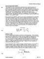
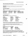
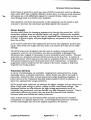
Poweris:',applied to the four-pin Jones type plug on the rear panel. Primary
+12.6 volt power, optional backup battery power, and two separate grounds
connect to the repeater power system. The primary supply and battery
inputs are diode isolated, so that the battery is normally isolated from the
load through a back biased diode until the primary supply goes away, at
which time the battery instantly begins supplying the power. The battery is
only necessary to continue operation of the controller - remotely
programmed information is stored in non-volatile memory and does not
require battery backup.
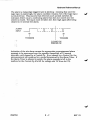
The two grounds should be kept separate back to the supply to prevent
digital noise from appearing in the audio signals. Both grounds (AGND and
DGND) must be connected to the power supply. Use # 18 or larger diameter
wire and keep it as short as possible. BOTH GROUNDS MUST BE
CONNECTED TO THE SUPPLY GROUND.
POWER CONNECTOR
/r{
2
-
+
BATTERY
BAT
+ 12V
+
AC
SUPPLY
@Z)
'F
(Initial Installation)
RC-850
Controller
DGND
AGND
2 -2
<;.t-:-:-:-:-;::)
4
1
2
3
4
ANALOG GROUND
+ 12.6 VOLTS
DIGITAL GROUND
BATTERY
8/87 V3
Hardware Reference Manual
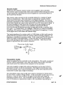
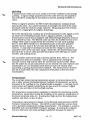
Carrier-Operated Switch
The output from the receiver which indicates that a signal Is present Is
called COS, or carrier-operated-switch. It's a logic signal which Is at a
particular logic state when a signal is at the receiver's input or the squelch Is
open, and at the opposite state when the squelch is closed. Most receivers
designed for repeater service have such a logic output called "COS", "COR",
"squelch gate", or something similar. With other receivers, such as
transceivers put into repeater service, it's necessary to fmd a usable logic
signal for COS. Look after the FM detector, following the noise amplifier and
rectifier in the squelch circuit.
Since signals from different receivers can vary in characteristics, the RC-850
controller is designed to accept a variety of logic levels and to accept "high
true" and "low true" signals. The only requirements are that a logic low be
less that .8 volts and a logic high be greater than 2.4 volts (up to about 15
volts). The COS input impedance is approxm1ately 10K ohms so that it won't
load down the circuitry providing the COS signal (but be sure to measure the
receiver's COS high and low voltage with it connected to the controller just
in case!). A DIP switch on the controller board allows selection of high or
low true based on what your receiver provides. See "Setting DIP Switch
Options" later in this chapter.
COS Input
Rin=10K
Vlow<.8V
Vhigh>2.4V
Push-to-Talk
The PIT signal is just as easy to interface to the transmitter. The controller
provides a solid-state switch closure to ground capable of sinking up to about
100 rnA from a positive source. Most any transmitter has a keying line
(PIT), so if a contact closure to ground normally keys your transmitter,
you're in business. If a logic high keys your transmitter, the controller also
allows PIT high true operation so that a pullup resistor on the-output can
define a logic high level to the keying logic. High or low true operation is
selected by a DIP switch option.
If your transmitter has a negative voltage on the keying line, it's necessary to
buffer PIT with a relay or other transistor circuitry. The PIT output is
capable of keying positive voltages only and may be damaged if connected to
a negative voltage. If greater than 100 rnA is required to key the trans
mitter, the PIT output can be buffered with a larger transistor or relay.
PTT Output
t--fI
v---''l
~
60V (off)
"IOOmA(on)
(Initial Installation)
2 - 3
8/87 V3
Hardware Reference Manual
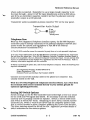
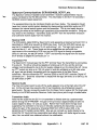
Receiver Audio
Audio from the repeater receiver needs to be supplied to the controller.
The receiver audio is mixed with other audio sources before being sent along
to the transmitter and phone line and is supplied on a prioritized basis to
the Touch-Tone decoder.
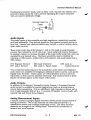
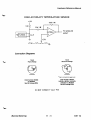
The receiver audio circuitry in the controller allows for a variety of signal
levels and impedances. The audio input is capacitively coupled, which
means that a DC level may be present on the signal supplied. The level is
internally adjustable so that a fairly wide range of input levels is acceptable,
but for best results the input audio should be .5 to 2.5 volts peak-to-peak. If
the level available is lower than this, the gain of the input stage can be
increased by adding a resistor to the controller board at R70 which
increases the gain of the non-inverting op amp input buffer to greater than
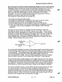
one (gain = 1 + (l00KjR70)). For example, if 300 mV p-p audio is available,
installing a 33K resistor at R70 (gain=4) is equivalent to supplying 1.2 volts
at the,input and is well within the deSired range.
The input impedance for receiver audio is lOOK ohms so that audio may be
picked off from anywhere inside the receiver without loading problems. No
impedance matching is necessary either. Find a point past the FM detector
where the audio is de-emphasized. It does not need to be squelch gated,
since audio gating circuitry is built into the controller. (Note that a COS
signal is required from the receiver, however.)
Receiver Audio Input
.S-2.SV p-p
capacitively
coupled [I
1E---1,...---I
.1 Trans.mitter Audio
AudioiS"supplied by the controller to the transmitter. The audio consists of
receiver, speech synthesizer, tone, link and phone patch audio, Switched
and mixed under the control of the computer in the controller.
The audio supplied is high level and low impedance so it's easy to fmd a
good place to inject it into the transmitter. The high level minimizes hum
and noise pickup, and it may be knocked down to the level required at the
transmitter's audio input stage if necessary.
The microphone input may be OK, but it may be necessary to knock down
the level with a resistor voltage divider. If the transmitter audio input is very
sensitive, it may be best to reduce the gain of its audio input stage by
changing a resistor value. The controller's audio output is DC coupled - it
may be necessary to capacitively couple to the transmitter depending on
(Initial Installation)
2 - 4
8/87 V3
...."
Hardware Reference Manual
where audio is injected. Remember to use a large enough capacitor to let
the lows through - about 10 uF for input impedances as low as 600 ohms,
and if it's an electrolytic capacitor, install it so that it's polarized correctly
(controller output is at DC ground).
Transmitter audio is available at phono connector "'IX" on the rear panel.
Transmitter Audio Output
t>---
4V p-p
de coupled
centered
around ground
Telephone Line
With the FCC Registered Telephone Interface option, the RC-850 Repeater
Controller may be directly connected to the national telephone network and
comes under the control and regulations of Part 68 of the Federal
Communications Commission (FCC).
(1) The RC-850 controller cannot be connected to party lines or to coin operated telephones.
2) In case of any malfunction of the RC-850 Repeater Controller or telephone line. disconnect
the unit from the phone line. If the RC-850 Repeater Controller Telephone Interface Board is
found to be inoperable. return it Advanced Computer Controls for repair. Do not attempt field
repairs or modifications as this violates FCC regulations and will void the warranty. Refer to
warranty infornlation supplied with the controller.
3) Before connecting the phone line. call the local telephone company. State the following FCC
required information:
FCC Registration Number: AU492x-69442-DP-E Ringer Equivalence: 0.8B Novation Phone Line Interface Part Number 490278 Connect one end of the modular cable to the phone line connector box,
usually located on the wall.
With the TP-3 Non-Registered Telephone Interface Board. run a wire from
the terminal block center tenninal directly to your system ground for
optimum lightning protection.
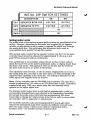
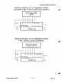
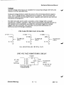
Setting DIP Switch Options
Switch settings on the RC-850 controller board select high or low true sense
for the COS and PIT signals (see below). It's necessary to set the switches
correctly now to properly control the repeater. Switch 1 selects COS sense
and switch 2 selects PIT sense. Assuming you don't have a control receiver
connected yet, switch 3 must be set ON so that the controller doesn't think
that a control receiver is active, therefore grabbing the Touch-Tone decoder.
The other switches should be left off for now. Appendix I provides details of
switch selections for the various options.
(Initial Installation)
2-5
8/87 V3
Hardware Reference Manual
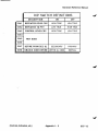
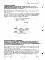
INITIAL DIP SWITCH SETTINGS DESCRIPTION
REPEATER RCVR COS
REPEATER TX PTT
SWl
SW2
SW3 Iffmmmmfmmmmmmmrmmmmmt~r~
SW4-8 It~tttrmmmmrttIttt~ff
ON
HIGH TRUE
HIGH TRUE
OFF
LOW TRUE
LOW TRUE
ON
OFF
'.'
Setting·Audio Levels
The audf6levels of the various internal audio sources are pre-adjusted at the
factory><'However, depending on the audio level supplied by the repeater
receiver, an adjustment must be made to optimize the signal level through
the analog delay line. Not perfonning this adjustment may result in
unacceptable audio quality through the repeater.
With normal audio received by the repeater receiver. pot Rl13 on the main
controller board should be adjusted for approximately 3 volts p-p at test
point TP2 as measured with an oscilloscope.
If an oscilloscope is not available, adjust the pot so that receiver audio is
about the same level as the speech synthesizer audio. or slightly louder than
the Morse code audio. This approach relies on the fact that the levels for
the other audio sources are preset at the factory.
This adjustment ensures that, on the one hand. clipping does not occur in
the analog delay line, and that on the other hand. you take advantage of the
signal-to-noise capability of the delay line. The setting is dependent on the
audio signal level supplied from the receiver.
Note: If;your controller uses an SAD4096 chip at position U35. then Rl13
should Be adjusted for 1.25 volts p-p at TP2 rather than 3 volts. Controllers
supplied~after early 1985 use a newer delay line sub-assembly which
operates at the higher signal level.
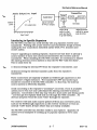
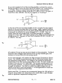
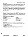
The transmit audio output level is now fIxed at apprOximately 4 volts p-p.
and should be knocked down and adjusted at the transmitter if necessary.
Do not load the audio output with less than apprOximately 600 ohms. If you'd like to change the relative levels of the various audio sources within the controller, refer to Appendix III, Adjustments. The controller includes audio processing (predictive attack agc) which reduces the transmitted audio level varations for different received levels. Don't try to get a linear"x kHz out for x kHz in" relationship with a deviation meter - the transfer function is shown below. (Initial Installation)
2-6
8/87 V3
Hardware Reference Manual
Audio Output
YS.
Transmitter
Input
Controller
Output
Level
I--~'-I
Audio
Input
stage
Adjust controller
for 4V p-p outputs
Deviation
Level
Adjust level
contro1 so that
audio just starts
to go into Umiting
I nput Level
Adjust Deviation
control for proper
peak deviation
Interfacing to Specific Repeaters
The RC-850 controller can work directly with any repeater receiver and
transmitter. Working with a bare receiver and transmitter simply involves
making the four connections desCribed earlier (COS, PIT, transmit and
receive audio).
If you're upgrading an existing repeater, chances are that there is already a
control system of some sort interconnected between the receiver and the
transmitter. When installing the RC-850 controller, it's necessary to disable
the existing internal control system so that the RC-850 "calls the shots".
This is easily done by
(1) disconnecting the internal PIT from the repeater's transmitter, and
(2) disconnecting the internal transmit audio from the repeater's transmitter. These connections are typically available at feedthrough capaCitors on the
transmitter's rf tight enclosure. The transmitter's PTT and audio input
should be connected to the RC-850 controller. In that way, the internal
control system is effectively disabled.
Avoid connecting to the repeater's "accessory" connector, if nne is. available,
unless you're very sure yoU-understand the existingcontroller~s.internal
operation. Connection in this way may result in dual audio and keying paths
- one through the repeater itselfand one through the '850 controller. An
obvious symptom would be audio "echo" through the repeater.
The receiver COS and audio may be picked off from any convenient point,
such as the feedthrough capaCitors on the receiver enclosure or from an
internal "COR" board, if that's where they are readily available.
The RC-850 controller can interface easily to any repeater. Appendix III shows several examples of hooking up to popular repeaters we've come across. (Initial Installation)
2 -7
8/87 V3
Hardware Reference Manual
(Initial Installation)
2 - 8
8/87 V3
Hardware Reference Manual
Chapter 3
Input / Output Characteristics
Basic interfacing of the RC-850 Repeater Controller for initial installation into
the repeater was described in Chapter 2 - Initial Installation. This chapter
provides a brief general description of the hardware II 0 characteristics.
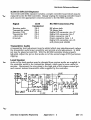
Logic Inputs
The logic inputs to the controller are high impedance with input logic levels
compatible with TTL, 5/12 volt CMOS. and logic levels found in many discrete
circuits. Logic low is defined as 0-.8 volts and a high may be 2.4-15 volts.
Voltages between .8 and 2.4 volts are undefined and must be avoided.
Unconnected logic inputs are internally pulled to the logic low state.
The logic driver should be capable of driving a 10K ohm load to a Darlington
transistor base. It needs to source at least 100 uA to be recognized as a logic
high. If the driver is not capable of sourcing suffiCient current. a pullup
reSistor may be added to a positive supply to source additional current in the
high state while the driver sinks the current in the low state.
Logic Inputs
Rin=10K Vlow<.8V Vhigh>2.4V Logic Outputs
The logic outputs from the controller are open drairi, high voltage. high
current VMOS transistors. A logic low 1s equivalent to a contact closure to
ground (actually about 5 ohms) and a logic high is an open circuit. The outputs
can switch positive DC signals and can sink up to 100 rnA when low (on) and
can withstand up to 60 volts when high (off).
The logic outputs can be interfaced to TIL and CMOS by adding a pullup
resistor to an appropriate supply to define the logic high voltage. For example,
interfacing to TTL or 5 volt CMOS can be accomplished by adding a 10K
pullup resistor to the 5 volt supply. Interfacing to 12 volt CMOS would require
a pullup resistor to 12 volts.
Logi c Outputs
~j--II 60V(ofO
100mA(on)
~~
(I/O Characteristics)
3 - 1
8/87 V3
Hardware Reference Manual
Interfacing to inductive loads, such as relay coils, requires the addition of a
protective diode across the coil to prevent damaging the output transistor
with an inductive kickback voltage.
V+
Dri vi ng I nducti ve
Loeds
Audio Inputs
The audio inputs to the controller are high impedance, capacitively coupled,
and level adjustable. They include inputs for the repeater receiver and up to
four link / remote base receivers (which may include a control receiver and a
spare audio source).
These input levels should be between 1 and 5 volts peak-to-peak (repeater receiver input should be .5-2.5 volts p-p). Input sensitivity may be increased by adding a resistor to increase the gain of the input buffer amp from unity (as supplied) to any deSired value. The input sensitivity may be doubled by inserting a lOOK reSistor, tripled with a 47K reSistor, and quadrupled with a 33K resistor. R70 Repeater Receiver
R87 Link I Receiver
R80 Link 2 Receiver
R81 Link 3 / Spare Audio
R86 Link 4/ Control Receiver 1wu unswitched audio inputs to the transmitter audio mixer and telephone audio mixer are available for bringing in additional audio sources, such as the Digital Voice Recorder. These inputs are 10K impedance and are not level adjustable, so they must be adjusted externally. Any audio present at these inputs will always appear at the output of the mixer. Audio Outputs
In addition to the repeater Transmitter Audio Output, a Processed Receiver
AudiO output is available for special applications, such as driving links or
remote base transmitters. It is an unbuffered, high impedance output with a
level of apprOximately 300 mV p-p. It consists of repeater receiver audio with
squelch tails and Touch-Tone stripped.
Analog Measurement Inputs
A sixteen channel analog-to-digital converter allows remote measurement of
analog parameters. Two of the channels are internally connected to a
temperature sensor and a voltage monitoring circuit. The other fourteen
channels are brought to the KAnalog Input" connector for connection to
external real world sensors.
(I/O Characteristics)
3 - 2
8/87 V3
Hardware Reference Manual
Measurement range: 0 to 5 volts DC (-9 to +16 volts absolute maximum)
Source impedance: inputs should be driven from source impedance <10K ohms
Serial I/O
The four serial I/O ports provided on the Computer Interface Board present
RS-232 compatible electrical characteristics.
(I/O Characteristics)
3 - 3
8/87 V3
Hardware Reference Manual
(1/0 Characteristics)
3 • 4
8187 V3
Hardware Reference Manual
Chapter 4
Sub-Audible Tone
The controller may operate in conjunction with a sub-audible tone decoder
(PL / private-line) for tone access and control (see Operation Manual - Access
and Command Modes).
1Wo PL logic inputs are available - one which qualifies for all PL activities and
another which qualifies only for user level command activities. For example,
users may operate PL 100 Hz allowing them access to the repeater and to user
level commands. Control operators may operate a different tone frequency,
such as 77 Hz, allowing them access to control operator level functions, as
well as user level functions.
The external PL decoder may be any device capable of supplying a logic signal
to the controller when PL is present on the incoming signal. We'll show two
examples - the popular Communications Specialists TS-32 encoder / decoder
and the Comm Spec TP-38 shared repeater tone panel. We'll also show how
to inexpensively remotely control a PL encode or decode frequency using the
TS-32 or 8S-32.
Controller PL Logic Inputs
The PL Logic Inputs may be driven by a sub-audible tone decoder which senses
the presence of PL tones on received signals.
The PL inputs may be configured to be high true or low true (Le.. high = PL
present or low = PL present). The input logic sense is configured by the
repeater owner with a programming command.
*5104s
*5112s
User/Control Op (Main) PL Logic Input
User Only P~ Logic Input
Logic Connector Pin 15
Analog Connector Pin 18
s = 0 => low true / active low s = 1 => high true / active high Communications Specialists TS-32
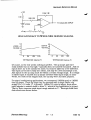
The Comm Spec TS-32 Encoder/Decoder unit can supply either a high true or
low true output. We'll select OUT-l which is low true. Jumper JU-l must be
removed and a 10K pullup resistor added to 12 volts or to 7.9 volt point "A".
The figure below shows how the TS-32 can be connected in the repeater
system. Audio input to the TS-32 Tone Input should come from a point in the
receiver where sub-audible tones have not been filtered out - the proper point
is receiver dependent and in some cases must be taken directly from the
discriminator. Other receivers have wide frequency response and sub- audible
tone is present at later pOints thoughout the receiver.
(Sub-Audible Tone)
4 - 1
8/87 V3
Hardware Reference Manual
The TS-32 includes a high pass filter which may be wired in-line with the
receiver audio to the controller. The high pass filter removes the sub- audible
tone components from the received signal so that they are not retransmitted.
Use of the high pass filter in your installation is optional. Some systems are
designed to allow user PL to pass unaffected, others filter out PL, and still
others regenerate PL on the repeater transmitter.
Note: The CTCSS Tone Decoder - Installed, available as a factory supplied
option for the controller, connects to the Receiver AudiO supplied to the
controller. Therefore, audio should be taken from the receiver at a point
where sub-audible tone has not been filtered out. The AudiO Filter in the
TS-32 is not used.
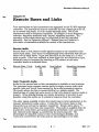
COMM-SPEC TS-32 SUBAUDIBLE TONE DECODER INTERFACE
COS
RECEIVER
AUDIO
DISC OR
AUDIO
1----------------iI cos
1-------.
...-_ _ _-1 RCVR
AUDIO
1--_.....,
RC-850
REPEATER
CONTROLLER
,..---31 PL
+V
10K
DECODER AUD 10
+V INPUT FILTER
IN
-.
-GROUND
AUDIO OUT-2 FILTER OUT
ENCODE
OUT
TS-32
(CUT JU-2)
(AVAILABLE TO
TRANSMITTER)
HANGUP
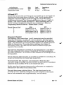
Comm Spec TP-38 Shared Repeater Tone Panel
The TP':'S8 tone panel is a cost effective replacement for community repeater
tone panels which are used to decode several different tones on a repeater
system. Different groups of users sharing the repeater are each assigned their
own tone frequency so that they don't need to listen to other users of the
repeater who are not part of their group.
In the application shown here, the TP-38 is used as a general purpose sub
audible tone decoder, connecting to the repeater receiver and providing a PL
logic signal to the controller.
The TP-38 decodes any or all of the 38 standard sub-audible tone frequencies.
With its DTMF option, each tone may be enabled or disabled independently,
remotely, using Touch-Tone commands (independent of the RC-850
command set). The unit can also cross code, or generate a different tone
output in response to a particular received tone.
(Sub-Audible Tone)
4 - 2
8/87 V3
Hardware Reference Manual
Use of the TP-38 can provide the system owner the ultimate in flexibility in
sub-audible tone operation.
Program the hang time in the TP-38 to zero and connect it to the RC-850
controller as shown below. The TP-38's "PIT" output becomes the PL signal
to the RC-850 controller.
'
~f*;~
DISCR
PH SUB-AUD
~~
RX AUD
COS
PL
PTT
RC-850
CONTROLLER
TX AUD
".:
Remotely Controlling the TS-32 / 88-32
The Comm Spec sub-audible tone encoder/decoders allow frequency selection
by DIP switch settings. The five DIP switches permit selection of one of 32
tones. It's easy to "remote" the DIP switches by connecting them to remote
control logic outputs of the controller.
The expanded general purpose remote control outputs from the controller
allow group control of two eight-bit groups (see Operation Manual - General
Purpose Remote Control). A single user Touch-Tone command can control all
eight bits simultaneously. We can use five bits of one of the groups to control
the TS/SS-32 frequency and a sixth if we want to tum it on or off.
Another method of controlling the encoder/decoder uses the PL frequency
bits included in the remote base frequency data stream supplied by the
controller. This approach is best used for PL encoding on the remote bases
since the information is stored in remote base memories along with the
transceiver frequency.
The TS/SS-32 internal circuitry may operate at its internally regulated 8V
supply or at a lower voltage if VRl is jumpered. With the circuitry shown
below, it's important that the TS/SS-32 internal circuitry operate at the same
voltage level as the shift registers. Otherwise, the logic signals supplied by the
shift registers may not drive IC-I07 in the encoder/decoder properly.
(Sub-Audible Tone)
4 - 3
8/87 V3
Hardware Reference Manual
REMOTE CONTROL OF PL FREQUENCY USING EXPANDED USER FUNCTION OUTPUTS (GROUP) SHIFT REGISTER
( 40948)
I
~10K
10
12
11
13
I
14 (J C-l 07)
I-
SS-32 C7/R6
TS-32 CSR202/C18 (DIP SWITCHES OfF)
rl
TS/SS-32
-
V+
REMOTE CONTROL OF PL FREQUENCY USING
LINK I REMOTE BASE COMMANDS
SHIFT REGISTER
(40948 or 74HC164)
I
~
10K
14
13
12
11
I
10 (I C- 1 07)
I-
SS-32 C7/R6 r-----f TS- 32 CSR202/C 18 (01 P SWITCHES OfF) V+
_________T_S_/S_S_-_3_2____~rl
(Sub-Audible Tone)
4 - 4
8/87 V3
Hardware Reference Manual
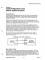
Chapter 5
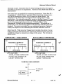
Control Receiver and Other Audio Sources Control Receiver
A control receiver may optionally drive Spare 2 Audio Input jack and the
Control Receiver COS logic input. When a control receiver is used, Link /
Remote Base channel 4 should be mapped appropriately (programming
command *576443).
AudiO input level should be in the range of 1-5 volts peak-to-peak. The
control receiver COS may be high true or low true - DIP switch 3 should be
set based on its logic sense - ON for high true, OFF for low true. If a control
receiver is not connected, DIP switch 3 1TU1St be on.
Except for the local mic, the control receiver has the highest priority for
access to the Touch-Tone decoder. The Control Receiver COS input to the
controller may be driven either by the receiver's COS logic output or by a PL
decoder signal in the control receiver for greater security. If a PL decoder is
used on the control receiver, PL would need to be transmitted on the
control channel to activate the control receiver function. Use PL if there is
spurious "grunge" on the control channeL
The control receiver may be optionally retransmitted out the repeater
transmitter by Control Op selection. It may also serve as the uplink for
remote telephone lines.
CONTROL RECEIVER INTERFACE
CONTROL
RECEIVER
AUDIO
cos or PL
,
,
~
~
SPARE
AUDIO 2
CONTROL
RCVR
RC-850
REPEATER
CONTROLLER
cos
Spare Audio 1 Input
The Spare Audio 1 input may be activated by user commands. When the
Spare Audio Input command is entered, the repeater transmitter is held on
and the audio supplied to this input is retransmitted by the repeater. The
function may be turned off by entering the user level Hangup command. A
programmable timer may limit the duration that the Spare Audio 1 function
is kept on in case the user forgets to tum it off.
(Control Receiver, etc.)
5 -1
8/87 V3
Hardware Reference Manual
The input may be used for a monitor receiver, site monitor microphone, or
other audio source.
'When the Spare Audio 1 input is used. Link / Remote Base channel 3 should
be mapped appropriately (programming command *576330).
&
WARNING
Part 97 rules prohibit the retransmission in the amateur service of signals
originating from other services. The Spare AudiO 1 input should not be used
in the amateur service; for example. for monitoring a NOAA weather radiO or
local police radio.
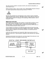
Digital Voice Recorder
ACC's'Digital Voice Recorder may interface to the RC-850 controller so that
any of the remotely recordable "tracks" may be addressed through the
Message Editor. Any programmable messages may include DVR tracks, as
well as synthesized speech, Morse code, etc.
Control signals are passed to the DVR through the Remote Base Data logic
output as part of the serial data stream supplied at that output. Information
from the DVR is supplied to the RC-850 controller at its External Device
Busy logic input,
AudiO from the DVR drives the Transmitter Mixer Input and may be level
adjusted at the DVR. Audio should be supplied to the DVR from the repeater
receiver.
Additional operational instructions for use of the Digital Voice Recorder with
the RC-850 controller are supplied with the DVR.
DIGITAL VOICE RECORDER INTERFACE
) SERIAL
IN
SERIAL
OUT
RB DATA
RC-B50
EXTERNAL 1/
REPEATER
DEVICE BUSY I'
CONTROLLER TRANSMITTER
"
MIXER AUDIO 1/
INPUT
AUDIO
OUT
I'
DIGITAL
VOICE
RECORDER
AUDIO IN
/
"
RECEIVER
(Control Receiver, etc.)
5 -2
8/87 V3
Hardware Reference Manual
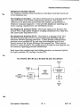
Chapter 6
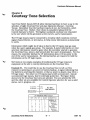
Courtesy Tone Selection
User Tone Select Inputs (UTI-3) allow external hardware to have a say in the
selection of eight Courtesy Tone sets (see Operation Manual - Courtesy
Tones). Remember that the hardware inputs do not, by themselves, select
the Courtesy Tone. Rather, their choice is considered along with the
Control Operator's choice. The highest numbered courtesy tone requested
is the one which will be generated at the end of a user's transmission.
The UT logic inputs may be connected to circuitry which monitors received
signal characteristics, or site status, to help convey information automatically
to users.
Information which might be of value to feed to the UT inputs may go away
wllen the user's signal goes away. For example, S-meter information or voter
selection information would be gone when the controller started to generate
the Courtesy Tone, about a half second after the user's transmission. For this
reason, the controller latches the UT information about 100 ms prior to the
end of the user's transmission. No external latches are required to hold the
information at the UT logic inputs.
We'll look at two simple examples of interfacing the UT logiC inputs to
eqUipment at the site to convey information on the Courtesy Tone.
Example #1. We would like to use the Courtesy Tone to tell us if the
repeater is operating on ac power or battexy backup. A signal indicating that
the battexy is powering the repeater, or that ac power is absent, may drive a
UT logic input. The other two UT inputs may be left unconnected - like all
unconnected logic inputs, they're ~ternally pulled low. The figure below
shows how the Courtesy Tone sets are selected. Two are selected by UT3
and the other six are available for Control Operator selection for use as alert
status, net in progress, etc.
no connect
no connect
UTI
UT2
HIGH on backup
battery power
UT3
RC-850
CONTROLLER
UT HARDWARE INPUT SELECT
un
UT2
UTI
SELECT
DESCRIPTION
L
L
L
NORMAL AC
l
l
l
l
H
1
2
H
H
l
3
H
4
-
H
L
L
5
BATTERY
H
H
H
l
H
6
H
L
7
H
H
e
(Courtesy Tone Selection)
- lOW PRIORITY
CONTROL OP
SELECTABLE
- HIGH PRIORITY
CONTROL OP
SELECTABLE
-
6 - 1
8/87 V3
Hardware Reference Manual
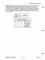
Example '2. Our system uses two receivers with a voter to select the signal
with the highest signal-to-noise ratio. We can take the voter's "receiver
selected" signals to the UT inputs to indicate which receiver was active
during the user's transmission. Additionally. we can supply an indication of
ac or battery power as before. In this example. Courtesy Tone # 1 would
never be selected, because the hardware UT selection would always request
tone 2 or higher.
HIGH
on RXI
UTI
sel ected
HIGH
on RX2
RC-850
CONTROLLER
UT2
UT3
selected
HIGH on backup
battery power
UT HARDWARE INPUT SELECT
UT3
UT2
UTI
L
L
L
L
L
L
L
H
L
H
L
H
L
H
H
H
H
H
L
L
H
H
H
H
(Courtesy Tone Selection)
SELECT
DESCRIPTION
1
-----------------
2
3
RX 1. AC POWER
RX2. AC POWER
- LOW PRIORITY CONTROL
- OP SELECTABLE
RXI, BATTERY
RX2,BATTERY
- HI PRIORITY COP SELECT
4
5
6
7
8
6 - 2
8/87 V3
Hardware Reference Manual
Chapter 7
Telephone Interface
The RC-850 controller has extensive phone patch and phone line control
capabilities which are described in detail in the Operation Manual
Telephone Interconnect. This chapter describes hardware considerations for
use of local and remote telephone lines.
Telephone Interface Board
An internal telephone interface board is available as an option for the
controller. It interfaces the logic and op amp type electrical signals from the
main controller board to tip and ring of the telephone system. It's available as
an FCC registered or as a non-registered interface. Both boards serve identical
electrical functions, but the FCC registered board is legally required for direct
connect to the public switched telephone network.
FCC Registered Interface - Installation information and FCC data for this
interface is provided in Chapter 2 - Initial Installation - Telephone Line.
Non-Registered Telephone Interface - This interface is similar electrically to
the registered interface. It may be used in applications where the controller
is connected to a PBX or other private system.
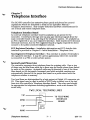
Second Local Phone Line
The controller supports three telephone lines for outgoing calls. One or two
of these may be local lines while up to three may be remote phone lines linked
by radio to the repeater. Autopatch calls maybe directed to one of the three
lines based on the Autopatch command used while autodial numbers are
automatically directed to the proper line based on a prefIx stored with the
telephone number in memory.
Two local lines are distinguished by a logic output at Digital I/O connector pin
23. This signal may be used to switch a DPDT relay to select one of the two
lines into the controller's Telephone Interface Board. The relay used should
be appropriate for telephone switching applications, such as an Aromat DS
series relay.
TWO LOCAL TELEPHONE LINES
i···..·····u...u··i
TIP
------~1o'~l___
R I NG
-----+--"!'-O'.. -+-___
~
:
TIP - - - - - '
TO TELEPHONE
INTERFACE
BOARD
...................!: DPDT
RELAV
RING - - - - - - '
(Telephone Interface)
7 - 1
8187 V3
Hardware Reference Manual
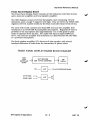
Remote Phone Lines
The controller can access up to three different remotely located telephone
lines for outgoing calls. From the user's standpoint. the patch directed to
remote phone lines operates exactly the same as when directed to a local
phone line. All the Autopatch and Autodial features are available. The
controller handles the signalling and control of the remote site.
The "downlink" from the repeater to the remote phone line site may be via
the repeater transmitter or one of the auxiliary link / remote base
transmitters. The "uplink" from the remote line site to the repeater may be
through one of the auxiliary link / remote base receivers or the control
receiver. The uplink and downlink are specified using Programming
commands (see Programming Reference Manual - Patch Restrictions and
Mapping).
Equipment required at each remote phone line site includes
• a transmitter on the "uplink" frequency
• a receiver on the "downlink" frequency
• a signalling decoder to control the phone line on/off hook. such as ACC's
HSC tone decoding board
• a simple phone patch. such as the Heathkit HD-15I5
• a sub-audible tone decoder. if the downlink is the repeater transmitter
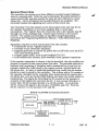
If the repeater transmitter is chosen to be the downlink, the sub-audible tone
decoder is required at the remote phone line sites. The potential exists for a
feedback loop consisting of telephone audio transmitted up to and out the
repeater transmitter, back down to the remote receiver, injected back into
the phone line. In order to break this feedback loop, audio into the remote
phone line may be gated by the controller. This is done with a PL encoder at
the repeater, activated by the controller when audio should be injected into
the phone line. such as during DTMF dialing, and when the mobile station is
transmitting. The signal for controlling the PL encoder at the repeater is
available at the Digital I/O connector pin 23. It may connect directly to a
Comm Spec TS-32 encoder/decoder or a SS-32 encoder. To control the
TS-32, connect the signal to the junction of CSR202 and C18. With the
SS-32. connect it to the junction of C7 and R6.
REMOTE TELEPHONE SITE BLOCK DIAGRAM
TRANSMITTER .-7PTT
AUDIO
•........._..__........._........_............._..
PHONE PATCH ,- PHONE
SUB-AUD I BLE!
(HEATHKIT HD- 151 5)
LI NE
r------vA~U!?!DI~Oi TONE
DECODER f-7
HOOKSWITCH
,
RECEIVER
L~.~~~.~.~.~~~ TS- ~~!..J
!
RELAY CONTACTS
SIGNALLING
DECODER
RELAY CONTACTS
(ACeS HSC BOARD)
(Telephone Interface)
7 - 2
8/87 V3
Hardware Reference Manual
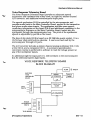
Sharing the Phone Line
Several controllers at a common repeater site can share one phone line with
handshaking among controllers to indicate when the phone line is currently
in use. When the "Phone Line Shared" mode is selected by the repeater
owner with a programming command, Digital I/O Connector pin 23 becomes a
low true Phone Une Busy output which may be or-tied with other controllers'
busy outputs. The signals are also connected to all the controllers' Phone Line
Busy inputs.
When a user attempts to bring up the patch and the phone line is in use by
another controller, the RC-850 controller responds by saying. "Busy". If the
phone line is not in use, the patch proceeds and the RC-850 controller pulls
the busy output low to indicate to the other controllers that the phone line is
now in use.
Each controller may be set for identical phone answer delays so that all
controllers answer an incoming call. Commands addressed toa particular
controller will keep it on the line while the other controllers will drop off
within 15 seconds.
MULTIPLE CONTROLLERS
SHARING A COMMON
PHONE LINE
~ PHONE LINE
/
/
'" ,
/
./
"
,
/
/
"
+V
,
/
10K
/
"
(Telephone Interface)
BUSY IN
PHONE LINE
BUSY OUT TIP
RC-850 CONTROLLER RING
PHONE LINE
BUSY IN
PHONE LINE
BUSY OUT
RC-850
CONTROLLER
PHONE LINE
BUSY IN
PHONE LINE
BUSY OUT
RC-850
CONTROLLER
PHONE LINE
BUSY IN
PHONE LINE
BUSY OUT
RC-850
CONTROLLER 7 • 3
-
8/87 V3
Hardware Reference Manual
Using An Existing Coupler
An existing telephone coupler or autopatch may be used in place of the
Telephone Interface Board option. If you choose to use such an existing
coupler or patch. the design of the proper interface to the main controller
board is entirely your responsibUtty. This section provides the specification
for the telephone interface connector at the main controller board.
Four basic signals must be interfaced to the existing coupler - telephone
receive audio. transmit audio, offhook logic control, and ring detect signal.
Telephone Receive Audio - This signal must be supplied from the coupler to
the main controller board and should be at least 1 volt p-p.
Telephone Transmit Audio - This audio signal is supplied from the controller
to the coupler and is approximately 1 volt p-p.
Offhook Logic Output - This 0 to 5 volt CMOS logic signal is supplied from the
main cgntroller board to the coupler and signals phone on/off hook. Use
programming command *51050 for low true or *51051 for high true.
Ring Detect Logic Input - This low true zero to five volt logic signal should be
supplied from the coupler to the main controller board. In its low state it
indicates ring voltage present on the phone line.
The signals are available on the main controller board at connector J7. Note
that the connector pin numbering is "1" upper left, then pin 2 is directly
across from it, i.e., the numbering zig-zags left/right left/right down the
connector. This is standard pin numbering for this type of connector. The
connections required at connector J7 are:
PIN
1,2,3
4
5
6
7
8
9 ..../,
10
SIGNAL
no connect
this line must be grounded
audio to phone line
audio from phone line
ring logic signal (5V logic input, low true)
offhook logic signal (5V CMOS output, programmable low/high true)
analog ground
digital ground (may tie to pin 9 and go to patch ground)
Dial Tone Detector When originating a phone call, the controller delays a minimum two second period before dialing in order to wait for dial tone. It dials "blind", however, assuming that dial tone is present after the delay. In the extremely rare installation where dial tone is conSistently unreliable, a logic input to the controller is available for connection to a dial tone detector. The Dial Tone Detect logic input causes the controller to wait until it indicates dial tone is present before dialing. The Dial Tone Detect logic input should be held high until dial tone is present. In general, the dial tone detector is not necessary, and if none is connected, the controller operates normally. (Telephone Interface)
7 - 4
8/87 V3
Hardware Reference Manual
Chapter 8
Rem.ote Bases and Links
Four remote base or link transceivers are supported by the RC-850 repeater
controller. The transceivers may be controlled by user commands to be off,
on in receive-only mode, or on in receive-transmit mode. 1\vo of the
transceivers may be frequency controlled. In addition to direct frequency
selection, frequency memories with "names" simplifies operation. The
operation of the transceivers may be scheduled as well as controlled
manually. See the Operation Manual- Remote Base and Links for a
discussion of commands available for control of the transceivers.
Receive Audio
Remote base or link receiver audio signals connect to the controller's link
audio input jacks. Each input is independently level adjustable with the pot
shown in the table below. Input level should be in the range of 1-5 volts
peak-to-peak. If the level aVailable is lower than this, the controller's input
sensitivity may be increased by inserting a 47K resistor on the main
controller board as indicated below.
Remote Base / Link
AudiO Jack
1
Ll
2
L2
SPI
SP2
3
4
Level Adjust
RIll
RIIO
RI09
RI08
Sensitivity Increase
R87
RBO
R8I
R86
Link Transmit Audio
AudiO for the remote base or link transmitters is available at two locations.
The processed main repeater receiver audio is simply receiver audio with
squelch tails and Touch-Tone removed by the audio processing circuitry.
This audio allows the link to sound identical to a simplex signal. The
disadvantage of using this audio source is that only repeater receiver audio is
present. Cross-linking (linking one remote transceiver to another) is not
possible using this audio nor is command response from the controller.
The other signal aVailable to drive the remote base or link transmitters is the
repeater transmitter audio output. It may drive the remote base or link
transmitters as well as the repeater transmitter. Simply add a phono "Y'
adapter to drive more than one transmitter. This audio is supplied from the
transmitter audio mixer and includes speech synthesizer, tone, and other
link channel audio signals as Switched by the microcomputer. The
advantages of using this output is that cross-linking is feaSible, and
commands entered from the links may be acknowledged to the links.
(Remote Bases and Links)
8 - 1
8/87 V3
Hardware Reference Manual
Audio Source
Processed Receiver Audio
Transmitter Audio
Level
.5V p-p
4Vp-p
Jack
PRX
TX
Impedance
10K
< 200 ohms
COSandPTT
Remote base or link COS and P1T signals are available at the the Digital I/O
connector and the Analog Input Connector. Link 1 and 2 signals may be
configured to be active high or active low (high true or low true) using
Programming Commands (see Programming Reference Manual - Logic I/O
Senses). Link 3 and 4 provide low true PTT. When interfacing Link 3 or
Link 4, be·sure to assign these channels as remote bases or links (see
Programming Reference Manual - Remote Bases / Links).
Remote Base or Link
1
2
3
4
COS
Digital I/O Pin 4
Digital I/O Pin 16
Analog Input Pin 22
Analog Input Pin 23
PTT
Digital I/O Pin 19
Digital I/O Pin 6
Digital I/O Pin 22
Digital I/O Pin 10
Frequency Control
The frequency of the remote base 1 and 2 transceivers may be controlled.
Frequency information, as well as PL, antenna direction, and band select
information is available at RB DATA output, clocked serially by the RB CLK
signal. The infonnation is recovered by shift register IC's, typically mounted
inside the transceivers. The serial scheme minimizes the number of
interconnect wires to the radiO and the number of discrete output pins
required of the controller.
The frequency information is provided for two transceivers as 3 1/2 digits of
BCD data compatible with common "thumbwheel" BCD type synthesizers,
plus offset information. An on/ off bit is also available for controlling power to
the transceiver.
Five PL frequency select bits plus an on/off bit is available for controlling a PL
encoder (or decoder) for the remote base transceivers.
Three band select bits respond to user commands. These bits allow
convenient design of multiple transceivers (such as IC2/3/4A) or a multlband
transceiver (such as Drake UV-3) on one remote base port.
Finally, seven bits of antenna direction select information are aVailable for
external servo-like control of an antenna rotor.
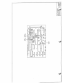
The serial data stream is defined below. The data burst is sent by the
controller on reset. scheduler changeovers, and in response to user remote
base or link commands, and is apprOximately 1 ms in duration.
(Remote Bases and Links)
8 - 2
8/87 V3
Hardware Reference Manual
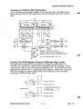
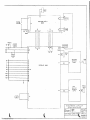
The serial-to-parallel conversion is perfonned by one or more 8-bit shift
registers. such as 74C164 or 4094B. external to the controller. Only those
shift registers required to capture the desired infonnation are required.
The first shift register in the chain recovers bits 40-47 (the last bits shifted
out). For example. two shift registers capture link / remote base 1
frequency infonnation. A chain of five are required to capture the PL
infonnation.
REMOTE BASE DATA TIMING DIAGRAM
--lnJlJl.nr
RB eLK
RBDATA
0
1
2
3
4
5
6
7
Direction 0
Di recti on 1
Direction 2
Direction 3
Direction 4
Direction 5
Direction 6
Bend Select 0
8
9
10
11
12
13
14
15
1011121314151617181 ::::
Bend Select 1
Bend Select 2
PL 0
PL 1
PL 2
PL 3
PL 4
PL ON/OFF
16
17
18
19
20
21
22
23
MHz DO
MHz 01
MHz 02
MHz D3
Plus/Minus Offset
Simplex/Duplex
5/6 KHz
Link On/Off
24
25
26
27
28
29
30
31
1O's KHz DO
10's KHz D 1
10's KHz D2
10's KHz D3
100'5KHz DO
100's KHz D 1
1OO's KHz D2
1OO's KHz D3
32
33
34
35
36
37
36
39
MHz DO
MHz Dl
MHz 02
MHz 03
Plus/Minus Offset
Simplex/Duplex
5/6 KHz
Link On/Off
40
41
42
43
44
45
46
47
10's KHz DO
10's KHz D 1
10's KHz D2
10's KHz 03
100's KHz DO
100's KHz 01
100's KHz D2
100's KHz 03
1441451461471
18wll Pl41 Pl31 PL21 PL11 PLol
les21es11esol
PL WORD 0-31, ON OR OFF
BAND SELECT WORD 0-7
DIRECTION WORD 0-127
LS
MS
1
I
LINK /
REMOTE
BASE 2
,
,
.._._...i
LINK /
REMOTE
BASE 1
RB SHIFT REGISTER CHAIN (FIRST SHIFT REGISTER PAIR REQUIRED FOR RB/LINK I, FOLLOWING S.R.'S NOT USED UNLESS THEIR SIGNALS ARE NEEDED) L~.? ................._.....................................~~j
!.!L.__._......._.._._....._.......................!.~j
REMOTE BASE / LINK 1
REMOTE BASE / LINK 2
(Remote Bases and Links)
8 - 3
s............1Q.j
j.~..
PL
L~.........!.: j§................().i
BAND DIRECTION
8/87 V3
Hardware Reference Manual
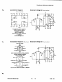
Interface to ICOM IC-22U Synthesizer
As an example of an actual interface to a particular radio, the figure below
illustrates an ICOM IC-22U transceiver as a synthesized two meter remote
base,
+9V
I
I
MS
LS, MS
LS I
100's
10's
J3 J3 J3 J2 J2 J2 J2 J2 567
1 2 3
4 5
4 5 6 1011 1213
ON
5
Of'F
0
,MS
LS, MHz X X J3 J3
3 4
X Jl
4
10K
RB
DATA
-600
SID
JI-2
+9
10K
+600
RB
JI-3
elK
40018
CONNECT IC-22U J2-6 TO +9V
LEAVE IC-22U "DUP" PIN UNCONNECTED
CONNECT IC-22U "SEND" TO CONTROllER PH
All IC'S MUST BE CMOS - NOT TTL
Driving Two Shift Register Chains at Different Logic Levels
The logic signals applied to the transceiver's frequency synthesizer, PL
encoder, etc., must be at voltage levels compatible with its circuitry. In the
case of the IC-22U above, the circuitry operates at 9V. The ICOM IC2/3/4A
synthesizers operate at 5V. Independent shift register chains may operate at
different voltages, as shown below, when it's necessruy to drive circuitry
operating at different logic levels.
·····........·....······..·..····..··..·1 +SV +9V
I RB DATA
-I r-----t-----T"------1i-----
9V log i c RB DATA
1.....---1111--_-4-__
SV 10 gi c RB DAT A
CONTROllER
+SV +9V Diodes isolote 9V logic
from SV logic.
--l t-----i-'"""T"------1r----
9V Iogi c RB ClK
'--~I------
SV logic RB ClK
(Remote Bases and Links)
8 - 4
8/87 V3
Hardware Reference Manual
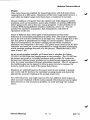
Controlling an HF Remote Base
An HF transceiver may be controlled through the repeater system using
ACC's ShackMaster SM-IOO. ShackMaster may connect to one of the
controller's four link ports and may support an ICOM IC-7S1, Yaesu Ff-7S7,
Kenwood TS-440S or TS-940S, and certain other HF transceivers. The
system permits repeater users to "operate" the HF station with similar
benefits offered by VHFjUHF remotes.
ShackMaster normally operates half-duplex, that is, it listens or transmits,
but not both at the same time, on the control channel. It does this through
its "control window" which forces it to listen periodically for your control
tranSmissions on the control channel. In this repeater application, since the
control transceiver is actually a full-duplex link port on the RC-8S0
controller, the control window isn't needed. Set ShackMaster's control
window delay to zero and no control window will be generated. When the
link is on, ShackMaster is always listening to the user,capable of decoding
commands to control the HF transceiver.
The figure below shows how the RC-850 controller may connect to
ShackMaster for control of the HF transceiver through the repeater. For
more information on ShackMaster, contact ACC.
RC-850 - SHACKMASTER INTERFACE
RC-850 CONTROLLER
SHACKMASTER SM-l 00
LlNKx PTT
PR IMARY RX COS
LlNKx COS
PRIMARY TX PTT
TX AUDIO
PRIMARY RX AUDIO
LlNKx RX AUDIO
PRIMARY TX AUDIO
(Remote Bases and Links)
8 - 5
8/87 V3
Hardware Reference Manual
(Remote Bases and Links)
8 - 6
8/87 V3
Hardware Reference Manual
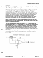
The alarm logic inputs to the controller provide over-the-air alarm
announcements when the alarm logic inputs are activated. The alarm
messages may be programmed by the repeater owner to indicate the nature
of each alarm. The alarms may be used as an indication of intrusion. over
temperature, or water on the floor. or as a weather radiO storm alert or
aviation ELT warning.
An alarm is activated by applying a logic high signal (2.4 - 15 volts) to the
alarm input at the Analog Input connector. The signals can be derived from
other circuitry. such as a temperature sensor switch or a limit Switch which
applies a voltage to the alarm inputs when closed. Alternatively, for more
security in intrusion detection applications, a pull-up resistor can be
grounded by a normally closed switch, and if the Switch is opened or if the
wires are cut, the alarm will be activated.
SITE ALARM APPLICATIONS
~
SENSOR
+V
/
,
~
/
ALARM
INPUT
RC-B50
REPEATER
CONTROLLER
ALARM
INPUT
RC-B50
REPEATER
CONTROLLER
ALARM
INPUT
RC-B50
REPEATER
CONTROLLER
NORMALLY
OPEN SENSOR
SWITCH +V L
-.
(Alarms)
~
{
NORMALLY
CLOSED SENSOR
SWITCH
10K
,
/
9 - 1
8/87 V3
Hardware Reference Manual
The alarm is rising edge triggered and is latching - meaning that once the
logic input is taken high, the alarm condition remains even if the logic input
is returned low. This insures that detectors such as limit switches for
intrusion detect cause a continuing alarm that does not cancel once the
switch is closed. The input must be taken low, then high again after being
cleared to re-activate the alarm.
ALARM
INPUT
t
TRIGGERS
TRIGGERS
CLEARED BY
CONTROL OP
Activation of the site alarm causes the appropriate preprogrammed alarm
message to be announced over the repeater transmitter at 10 second
intervals. until cleared by a Control Op. If not cleared by a Control OPt the
announcement will continue for a period determined by the Alarm Timer. If
the Alarm Timer is allowed to expire. the alarm message is left in the
mailbox for the Control Op (it's left for callsign slot 78. from slot 79).
(Alarms)
9 -2
8/87 V3
Hardware Reference Manual
Chapter 1 0
General Purpose Rem.ote Control The controller provides logic outputs available for general purpose,
scheduled, remote control of equipment at the repeater site.
Remote Control Logic Outputs
The Remote Control Logic Outputs allow remote control of equipment at the
repeater site with user level commands. Each logic output may be
controlled independently. The current state of each output may be
interrogated and states may be commanded high or low remotely.
Programmable response messages return information indicating the
meaning of the high and low states of each output in your system. For
example, one output may control an antenna relay which selects between an
omnidirectional antenna and a beam. The response messages could be
configured by the repeater owner to be "OMNI" and "BE.A11". The response
to interrogation or change state commands would be "OMNI" or "BEAM",
based on the current or newly commanded state.
~
Other eqUipment at the repeater site controllable by the remote control
outputs could include a voter, remote base transmitter high/low power, an
ATV camera and transmitter to provide a view from the repeater site on
command, etc.
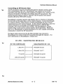
Six open collector outputs are available directly at the DIGITAL I/O
connector for remote control.
An expanded mode offers up to 64 remotely controllable outputs, available
from a serial data stream shifted out by the controller. The expanded mode
is selected with programming command *51061 (see Programming
Reference Manual- Logic I/O Senses). ·The outputs can be recovered by a
series of shift registers, or by using one or two FC-l Frequency Control
Boards. Thirty-two of these outputs may be scheduled while the other 32
power up in the low state and are affected only by user commands.
The expanded mode redefines the UFl, UF2, and UF3 output pins to provide
a serial data, clock, and transfer signal at those pins for the 64 UF outputs.
In the expanded mode, all "User Function" (UF) outputs appear at the shift
register outputs, while UF4, 5, and 6 remain aVailable at the connector pins
directly. as well.
When any of the outputs UFl-6 are interrogated, a short (= lms) pulse is
generated o
n that output - that is, the output toggles to the opposite state
and back. The pulse is too short to disturb eqUipment being controlled. but
long enough to trigger a one-shot or 555 timer to stretch to any duration
required.
(General Purpose Remote Control)
10 - 1 8/87 V3
Hardware Reference Manual
With Version 3.4 firmware, several of the output pins may be redefined to
serve specific functions based on other controller selections. These are
described in Appendix I - Controls, Indicators, Connectors. and DIP
Switches.
===]
===J-'--__
COMMAND OUTPUT HIGH
COMMAND OUTPUT LOW
SAYS "HIGH"
MESSAGE
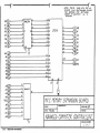
SAYS "LOW"
MESSAGE
SAYS "HIGH"
MESSAGE
SAYS "LOW
MESSAGE
INTERROGATE OUTPUT (1-6)
or
':::'EXPANDED USER FUNCTION TIMING DIAGRAM
'-I'-.~'"
--~
UF elK
1413\2\1 \
UF DATA
___--lrl
UF XFER
V+
16
16
IS
2 D
15
OS 9 2 D
3 elK
4094B
3 elK
4094B
1 XFER
S 1 XFER
0001 020304050607
0001 020304 050607
4 5 6 7 1413 12 11
-:"
4 5 6 7 14131211
40948
8
-:"
5758596061636364
UFI 2 3 4 5 6 7 8
910111213141516
Y+
10K
UF OAT A --+-_ _ _ _ _ _- . l
EXPANDED USER FUNCTION REMOTE CONTROL OUTPUTS
(one 40946 per 8 outputs,
to 64 outputs tote])
V+
10K
UF CLOCK
10K
':"
UF XFER --...._ _ _ _ _ _ _--1
(General Purpose Remote Control)
10 - 2
8/87 V3
Hardware Reference Manual
Chapter 11
Relllote Metering Operation of the metering capabilities is described in the Operation Manual - Voice Response Telemetry. This chapter describes hardware design and interfacing techniques for custom metering systems. S-Meter The controller allows users to read back their S-meter reading in synthe sized speech. An S-meter signal voltage from the repeater and remote base receivers can be applied to the controller's analog inputs. Two S-meter meter faces are available. One is appropriateJor reading the repeater receiver (02) and the other for remote base receivers (30). Meter face 02 measures the S-meter signal approximately one second into each repeater user transmission. The measured value is stored in memory, and if the user requests an S-meter reading, the stored value is read back in S-units. The user should remember to key down for a minimum of one or two seconds to ensure that the controller has had a chance to check the meter. Meter face 30, like most other meter faces, makes its measurement when the user's command is evaluated, at the end of his transmission (or after a "D" key which forces command evaluation). This meter face is useful for checking the signal strength of remote base or link signals. Many receivers, such as the Spectrum SCR-200, have internal signal strength circuits which may be tapped to provide a signal voltage to drive the controller. Other receivers may not have such a circuit - circuitry to obtain an S-meter voltage appropriate for the Motorola Micor is shown below. It can be easily adapted to other receivers with relatively low frequency 1.f. 'so The meter voltage would ideally range from zero to five volts. However, if the voltage range is too high, it can easily be knocked down with a resistor voltage divider. If it does not range all the way to five volts, the reading will simply "top out" at less than S9+60. As an interface example, the Spectrum Communications SCR-200 receiver S-meter output can drive the RC-850 controller as shown below. The meter itself should be disconnected from the circuit, Since it would load down the signal voltage to be measured. (Remote Metering)
11 - 1
8187 V3
Hardware Reference Manual
The Motorola Micor may be metered with the circuit shown below. Connect
the circuit to Point H (UHF receiver) which is after the output capacitor
Uunction C165, L127, R131) at the first Lf. amplifier. The rectified signal is
amplified with an op amp and adjusted to match the RC-850 controller's
S-meter "meter face",
5-METER (5-UNITS, DB OVER 59)
READBACK
59+60
59
50 I1111111I11"11j11111111
I I I I I I I I , 111111111111111
1 I I I , lijiili
I
o
5
234
INPUT VOLTS
ace
l
APPLICATIONS:
REPEATER RECEIVER S-METER
REMOTE BASE RECEIVER S-METER
SPECTRUM COMMUNICATIONS SCR-200
S-METER INTERFACE
5CR-200 RC-850
~
S-METER
___________~ ANALOG
INPUT
10K
MOTOROLA MICOR S-METER INTERFACE
.>--..J...-_ TO
ANALOG
INPUT
68pF
®-1~~~
CR2
I
100pF
CR l,CR2 - germanium
Adjust gain to produce an "S3" readout in voice
with 1uV signal applied to antenna input.
(Remote Metering)
11 - 2
8187 V3
Hardware Reference Manual
Quieting
A measurement which can be as useful as S-meter readback is percentage
quieting. A signal voltage proportional to the noise level can be applied to
the controller's analog inputs and permit a percent quieting readback to
users.
When no signal is present, the FM receiver discriminator contains broad
band audio noise. As a carrier increases in strength, the level of the noise
decreases until the receiver is fully "quieted". Measuring the level of noise
present on a signal gives the degree of quieting.
Since the discriminator contains the intended baseband audio signal as well
as some level of broadband noise when a signal is present, a quieting
measurement circuit should examine only relatively high frequency noise so .
it isn't fooled by voice. The mtered noise can then be rectified to form a DC
voltage which may be measured by the controller to read.back quieting.
Since a nOise filter/rectifier is a fundamental part of all noise operated
squelch circuits, most of the circuitry may already be present in your
receiver. It may only be necessary to boost the DC voltage to match the
controller's zero to five volt input range. Otherwise, the discriminator may
directly drive a circuit which provides band pass noise filtering, an "ideal"
rectifier. and scaling circuit.
The controller's meter faces read in inverse percent from 100 to O. 1\vo
quieting meter faces are available. One is appropriate for reading the
repeater receiver (04) and the other for remote base receivers (32): Meter
face 04 makes its actual measurement at one second into each repeater user
transmiSSion so it is necessary to key down at least one second when
requesting a quieting measurement readback. The measurement of meter
face 32 is made when the user command is evaluated, at the end of his
transmission.
Temperature
The controller allows placing temperature sensors at various places at the
site to allow remote synthesized speech readback of temperature as well as
inclusion of the readings in any programmable messages.. A running record
of the lowest and highest temperature are also stored in memory, tagged
with the time and date of the low/high reading.
The temperature measurement capability is valuable for monitoring outside
temperature, temperature inside the building, in the cabinet, temperature of
the power amp heat sink, etc. Knowing how high and low the temperature
reaches, and when, is also of value.
Temperature measurement is based on the National Semiconductor LM335
Precision Temperature Sensor. The LM335 is electrically like a zener diode
With a precision temperature/voltage characteristic. It's available in a plastic
(LM335Z) and metal (LM335H) transistor package. If sensing the tempera
ture of a heat sink, the metal package is preferred because it's easier to
(Remote Metering)
11 - 3
8/87 V3
Hardware Reference Manual
thermally couple. Remember that the metal package is tied to the negative
pin which is ground in our application. Portions of the LM335 data sheet are
shown below.
1\vo meter faces are available for measuring temperature. Meter face 05
lemperature - LM335 Sensor" operates with an extremely simple circuit
the LM335 temperature sensor IC and resistor as shown below. The
resolution of the meter face is ±2 degrees which is adequate for many
applications. The internal temperature sensor on Analog Channel 15 uses
this circuit. This meter face is calibrated using a programming command
(see the Programming Reference Manual - Telemetry Meter Faces
Temperature Calibrate for the calibration procedure). The procedure is
performed on one channel and applies to aU channels with this meter face
assigned. The sensors normally have an untrimmed accuracy of approxi
mately one degree, so that calibrating one channel calibrates them all.
Meter face 06 - "High Accuracy Temperature" provides the option of a one
degree resolution measurement but requires an external op amp circuit to
amplify the voltage vs. temperature change of the sensor. The circuitry is
shown below.
TEMPERATURE - LM335 SENSOR
HIGH ACCURACY TEMPERATURE
05
06
READBACK-DEGREES
o 75
READ BACK -DEGREES
+5.55 mV/deg F
11111111 1111111 jlllIlllllllI 11111111111111111111111
o
ace
2
3
I NPUT VOLTS
4
75
-27.77mv/deg F
0
.
11111 jlllIlllllllllllllllllllllllllllllllllllllllll
o
5
234
ace
APPLICATIONS:
INDDDR, OUTDOOR TEMPERATURE
PA"HEAT SINK TEMPERATURE
CABTNET TEMPERATURE
5
INPUT VOLTS
APPL I CAT IONS:
INDOOR, OUTDOOR TEMPERATURE
PA HEAT SINK TEMPERATURE
CABINET TEMPERATURE
TEMPERATURE SENSOR
+ 12V
10K
·......................................
..
·
i
.
LM335
!
...----
TO ANALOG
INPUT
.1 uF
:................................u.: (Remote Metering)
11 - 4
8/87 V3
Hardware Reference Manual
HIGH ACCURACY TEMPERATURE SENSOR
+ 12V
10K I···············~·~·~·~·~···!
~
:
100K 1% 20K 1%
TO ANALOG
INPUT
.1 uf
:.u•••..u ..........................: z3V
+Vreg~
Connection Diagrams
TO·92
Plastic PICkage
T0-46
Metll Can PICkage·
IOTTOM VIEW
IOTTOtilVIEW
• Case i~ connected to negetive pin
Order Number LM135H,
LM235H,-LM335H,LM135AH,
LM235AH or LM335AH
See NSPlckage H03H
Order Number LM335Z
or LM335AZ
See NS PacklgeZ03A
DO NOT CONNECT "ADJ" PIN
(Remote Metering)
11 - 5
8/87 V3
Hardware Reference Manual
Voltage
Several voltage meter faces are available for measuring voltage with full scale
values of 16, 32, and 256 volts.
Scaling of voltage levels to match the zero to five volt measurement range is
easy - just a voltage divider composed of two resistors. The 16 and 32 volt
scales are useful for monitoring DC power supplies and batteries and internal
test pOints of equipment.
The 256 volt scale can be used to monitor ac line voltage with a simple
transformer, rectifier, and fIlter. This can be particularly valuable if power at
the repeater site Is unreliable, and with the automatic high/low storage
tagged with time and date, the controller can provide information on
brownouts and overvoltage conditions.
VOLTAGE METER FACE SCALING
0-16V -----,
0-32V ----,
11.3K
0-256V -----,
27.41<
255K
TO ANALOG
INPUT
5.11 K
TO ANALOG
INPUT
TO ANALOG
INPUT
5.11 K
5.11 K
(ALL RESISTORS ARE 1% METAL FILM)
LINE VOLTAGE MONITORING CIRCUIT
1N4001
10K
AC LINE
115V
NOMINAL
E
-
(Remote Metering)
11 - 6
TO ANALOG
INPUT
(2.25V DC for
115 VAC)
8/87 V3
Hardware Reference Manual
Current
Meter faces are available for measuring current with full scale values of 4,8,
16, and 32 amps, and 64 microamps.
Measuring current requires a circuit which develops a voltage proportional
to current. This can be easily accomplished with a small value current
sensing reSistor. and a differential. or instrumentation type amplifier,
constructed with an op amp and four resistors. The output of the op amp is
equal to the current times the sensing resistor times the voltage gain of the
amplifier. The value of the sense resistor that should be used depends on
the maximum load current since the voltage drop across the resistor
reduces the voltage to the load. Be sure to calculate the worst case power
dissipation of the resistor (I2R) and use an appropriately rated resistor.
Ideally. a power supply with remote sensing capability would be used with
the sense return after the sensing resistor. That way, the voltage to the load
would be independent of current.
The four resistors around the op amp should be 1 or 2 percent metal film
types (available from RCA in "bubble pack"). Be sure that the common mode
input voltage range of the op amp will accomodate the operating voltages
that result from resistor/gain selection. For example, anLM324 or LM358
op amp operating at + 12 volts and ground will operate properly with input
voltages between zero and ten volts (input common-mode voltage· range from
data sheet).
An example is shown below for measuring current drain from a repeater
power supply.
CURRENT MONITORING CIRCUIT
I~
Rsense
+
Vs
-
R2
>-........-- Vout=
(Remote Metering)
11 - 7
~T x Rsense x I 8/87 V3
Hardware Reference Manual
Power
Nine meter faces are available for measuring power, with full scale values
ranging from 2 to 256 watts. Resolution of the lower range meter faces is .1
watt while the higher range meter faces have a resolution of one watt.
Remote readback of rf power from the repeater site helps diagnose system
problems. such as transmitter, power amp, feedline, or antenna difficulties
before going to the site so that you can go prepared. It also permits you to
evaluate SWR during different weather conditions, and so on. You can
monitor the repeater's transmitter, link transmitters, and other rf
eqUipment at the site.
Power is different than other types of measurements in that meter
deflection is not linearly proportional to power level. The scale Is expanded
out at the low end and crowded in at the high end. This Is largely due to the
fact that power is proportional to voltage or current squared. There are
other non-linearities in the meter's sensing circuits which contribute
additional non-linearities in the scale. The power meter faces in the RC-850
controller are based on a power proportional to voltage squared relationship,
which provides readings accurate to a few percent. Remember that a 25%
error is only 1 dB.
'
As an actual interface example, we'll show how to interface the Daiwa
CN-550 140-250 MHz dual needle meter to the controller. The CN-550 has
its sensors mounted in a shielded enclosure with rectified DC output for
forward and reflected power available at two feed through capaCitors which
drive the meter movements through adjustable resistors. The DC voltages at
the feedthroughs can be tapped to drive op amp circuits to increase the
levels to match one or more of the power meter faces.
ReSistors are selected based on the power level of your system to provide
zero to five volt DC levels to the controller's analog inputs and should be
adjusted for accurate reading at the normal power level.
.
For reflected power, you might want to drive two different meter inputs to
allow accurate readback of both normal (small) reflected power and a higher
full scale face in case of antenna problem, to avoid "pinning" the talking
meter.
(Remote Metering)
11 - 8
8/87 V3
Hardware Reference Manual
POWER - 0-256W (1 W RESOLUTION)
16
READBACK ·WATTS·
o
I
16
64
I
,
1111 J111111 I Ii I'll 111111111
o
ace
2
T
I :.
4
5:;
128
T
II I
JI IiI
3
256
I I 11111 I
~
&
.'
1
INPUT VOLTS
APPLICATIONS:
REPEATER FORWARD POWER
REMOTE BASE FORWARD POWER
DAIWA
F~----------~
TO ANALOG
INPUT
(FORWARD)
CN-550
WATTMETER R t - - - - - ,
Rl
GA IN = 1 + R2 + R3
Rl
R2
R1
TO ANALOG
INPUT
(REFLECTED,
HIGH SCALE FOR FAULT CONDITION) Rl
(Remote Metering)
R3 TO ANALOG
INPUT
(REFLECTED,
NORMAL
SENS IT I V lTV)
11 - 9
8/87 V3
Hardware Reference Manual
Everything You Need to Know About Op Amps (at least to get started) Designing custom circuits for creative interfacing of sensors to the RC-850 controller is easy, but it does require a basic understanding of op amp circuits. Although op amps are the most common analog function block, they may seem like black magic until you understand a few simple principles. We'll try to summarize the basics of op amps here, and you should be an expert when you leave the page! The important characteristics of op amps are: • Op amps have (almost) infmite gain
• Op amps have inflnite input impedance and draw no input current
• Op amps have two inputs: inverting and non-inverting
• In linear applications, the op amp likes to stay out of saturation
• To stay out of saturation, the op amp would like the voltages at its inputs
to be equal, and as circuit designers, we're willing to help, through
fe~dback
The bi;lsic op amp symbol is a triangle with the inverting (-) and non
inverting (+) inputs on the left and the output on the right. The op amp's
basic goal in linear applications is to stay out of saturation. If the op amp
saturates. or bangs its head against the supply rails, it becomes useless in
linear applications. Since it has (almost) infmite gain, the only way the
output voltage won't be infmite is if the two inputs are at exactly the same
voltage. Almost infmity times zero is zero!
INVERTING - - - - I
INPUT
NON-INVERTING _~
INPUT OUTPUT
An op amp with feedback (a portion of the output signal routed back around
to the inverting input) keeps out of saturation through a concept called the
"virtual ground". This simply means that negative feedback from the output
to the inverting input forces the inverting input voltage to equal the
non-inverting input voltage. Since in many applications the non-inverting
input:;is taken to ground, the inverting input is dubbed "virtual ground".
If the inverting input voltage happens to be higher than ground, the output
voltage drops. pulling the inverting input voltage back down towards ground.
If it happened to be below ground, the output would rise. pulling the input
up to ground. The point to remember is that if the op amp is not saturated,
both inputs are held at exactly the same voltage by the negative feedback.
Now if we remember that no current flows into the op amp inputs. it's easy
to understand how to calculate the gain of simple inverting and non
inverting amplifler circuits. The current flowing through the input resistor,
which we can calculate. determines the current which will flow through the
feedback resistor. Since we know the currents and reSistor values. we can
determine the voltage drops, and therefore. the gain.
(Remote Metering)
11 - 1 0
9/89 V3
Hardware Reference Manual
If one volt is applied to Rl of the inverting amplifier, we know the current
flowing through Rl since the other side of the resistor is at "virtual ground",
I = (IV/Rl). Since no current flows into the op amp, it all must flow
through R2, creating a voltage across R2 of V = (R2 x IV/Rl). The gain, or
Vout/Vin is then -(R2/Rl). See why it's negative, or "inverting"?
R2
lV
1V X -R2
Rl
In the case of the non-inverting amplifier circuit, we apply the input signal
directly to the non-inverting input of the op amp. Again,· negative feedback
forces the inverting input to be at the same voltage (althollgh in this case it's
not ground), so we know the current through RI. I= ·IVfRI. Since no
current flows into the op amp input. it all flows through R2, creating a
voltage of (IV/RI x R2). The output voltage is the voltage across Rl plus the
voltage across R2. The gain, or Vout/Vin, is therefore (Rl/RI + R2/Rl), or
(1+ R2/Rl). See why?
R2
1V X (1 + R2)
Rl
IV
All analysis oflinear op amp circuits is based .on these principles .. Feedback
keeps the input voltages equal because of the op amp's infmite gain, and
because no current flows into the op amp inputs.
As one more example, we'll analyze the HighAccuracyTemperature Sensor
circuit. The LM335 temperature sensor and its IOKpulIup resistor form a
low impedance voltage source. The voltage at the junction is (relatively)
independent ,ofthe load current drawn from the.node.We know easily that
the gain of the circuit is -5 (-IOOK/20K). The op amp inverting input (-) is
not at ground, however. It's kept at the same voltage as the non-inverting
(+) input by feedback. The effect is to offset the signal voltage from the
LM335 as well as to invert and amplify it - in this application to match the
High Accuracy Temperature Meter Face.
Stable metal fIlm, 1% resistors are recommended (except the IOK pullup) to
keep the circuit stable over temperature since small offset or gain changes
result in significant temperature reading errors.
(Remote Metering)
11· 11
9/89 V3
Hardware Reference Manual
+ 12V
lOOK 1 %
>---
TO ANALOG INPUT
+Vreg
HIGH ACCURACY TEMPERA lURE SENSOR SCALING
5
lM335 4
VOLTAGE 3
2
5
OUTPUT 4
VOLTAGE 3
2
1
0
1
a
a
50
100
150
TEMPERATURE (degrees F)
a
50
100
150
TEMPERATURE (degrees F)
Of course, in the real world, nothing is perfect. The op amp's gain isn't
really infinite but is very high - typically about a hundred thousand. And its
inputs don't try to be exactly the same, but may be offset by a few millivolts.
The input current isn't really zero either, but may be a few microamps or so.
And inputs to the op amp must be within a certain voltage range. If a voltage
at either input is outside the op amp's common mode input range, in other
words, too close to the supply rails, the op amp won't function properly.
For signal conditioning applications, we recommend LM324 quad or LM358
dual op amps. These op amps can be operated with a single twelve volt
supply(V+ = 12 volts, V- =ground). Unlike 741 type op amps, these allow
input signals to extend down to their V-, which in our application is ground.
That is, their common mode input range extends to V-. Excerpts from their
data sheets are shown below.
(Remote Metering)
11 - 1 2
9/89 V3
Hardware Reference Manual
Connection Diagram
Schematic Diagram
Dual-In-Line Package
OUTPut. INPUT.·
INPUT C'
OUTPUT I INPUT ,-
II'PUT 1·
(Each Amplifier)
v·
GND
INPUT l"
I~'UT]-
OUTPUT 1
v·
INPUT
t·
I"'UT ,-
OUTPUT 2
TO' \IIEW
Order Number LM124J, LM124AJ, LM224J, LM224AJ, LM324J, LM324AJ or LM2902J See NS Package J14A Order Number LM324N, LM324AN or LM2902N See NS Package N14A Connection Diagrams
(Top Views)
Schematic Diagram
(Each Amplifier)
Metel Can Pecke.
vv'
Order Number LM158AH, LM158H, LM258AH,
LM258H, LM358AH or LM358H
See NS Package H08C
V'
OUTPUT A
IIIVERTIIIG INPUT A
~--+-- OUTPUT.
IION~IIVERTIIIG ...;;,3.......----1
IIIPUTA
GilD -01----'
L--t'--
,. II01l-lIlVERnll; IIIPUT.
,
Order N'Jmber LM358AN, LM358N or LM2904N
(Remote Metering)
11 - 1 3
9/89 V3
Hardware Reference Manual
(Remote Metering)
11 - 1 4
9/89 V3
Hardware Reference Manual
Chapter 12
Principles of Operation
This chapter provides an overview of the principles of operation of the
RC-850 Repeater Controller.
The controller consists of several boards interconnected with simple
cabling. The Main Controller Board contains the microcomputer with its
CPU, ROM, RAM, E2PROM, I/O, and fail-safe circuitry, E 2PROM programmer,
audio processing circuitry, audio switching and mixing circuitry, tone
generator, the Touch-Tone decoder, and various I/O and control circuitry.
The Telephone Interface Board provides the interconnect to the phone line,
providing isolation, protection, impedance matching, ring detection, and
on-hook/off-hook control. It also provides an electronic hybrid which
permits duplex patches and a received audio agc circuit. The FCC registered
board complies with FCC Part 68 regulations regarding telephone inter
connect to the public switched telephone network.
The Front Panel Display Board provides visual display indicators for internal
and I/O status and amplifiers for a local microphone and speaker.
The Voice Response Telemetry Board includes a speech synthesizer, time of
day clock, and analog measurement circuitry, plus additional microcomputer
logic inputs.
The Computer Interface Board provides four serial I/O ports along with a
socket for additional firmware memory and two Touch-Tone decoders.
RC-850 REPEATER CONTROLLER
BLOCK DIAGRAM
r'-'T"E~Lp'H'ON-E-'-'l
INTERFACE !
iL ....._BOARD
i
.....____.____!
I------i;
MAIN
CONTROLLER
BOARD
i""F'R'O-NT-PA'NEL"'l
DISPLAV
I
BOARD
i
.......__......_._-_.
I------i'
:
:
r"y-O'j'CE RESP. ~
TELEMETRV !
I------i:
L_.
~OARD
I
! .COMPUTER
I------ii
I
INTERFACE
BOARD
! ...............................................! (Principles of Operation)
12 - 1
8/87 V3
Hardware Reference Manual
Main Controller Board
The Main Controller Board provides a complete, stand alone repeater
controller with all the features of the RC-850 controller except Telephone
Interface. Front Panel Display, Voice Response Telemetry, and Computer
Interface (see Chapter 1 - Specifications and Features).
The board is powered by a single external +12 volt supply, and the necessary
+5, +21, and -9 volts for the various circuitry are derived on- board (Ul,
U24, U25).
The crystal controlled clock for the microcomputer and various other
circuits on the board is derived from the 3.58 MHz oscillator on the
Touch-Tone decoder chip (U40).
The CPU is a CMOS, low power, 80C85 (U4). The CPU provides the
microcomputer's registers (including the accumulator), arithmetic logic unit
(ALUl-, instruction decode, interrupt control, and timing and control
circuitry.
The CPU uses a multiplexed data bus. The address is split between the 8 bit
address bus and the 8 bit multiplexed data bus. The 8 bit 74HC373 latch
(U5) de-multiplexes the low order address information from the multiplexed
data bus.
The address decoding circuitry (U14, U33) generates chip select signals for
the various memory and I/O devices in the microcomputer.
Several fail-safe protective circuits help prevent CPU lockup in case of soft
error. A watch-dog timer (U11, U34) is strobed every five seconds by the
microcomputer software. If the watch-dog timer is allowed to tiIDe out, as if
the CPU were to hang up, the CPU is reset, initializing program execution.
Circuitry monitors the +12 volt and +5 volt supplies (Ql, Q2, Q4) and if
either drops below the level required for proper operation, the CPU is
clamped reset so that it initializes properly when the supply voltages are
restored to their proper levels.
The CPU is capable of addressing up to 64K bytes of memory. Five memory
sockets are provided on the Main Controller Board. Each socket is decoded
as an 8K byte site and is compatible with 2K, 4K, and 8K devices, allowing
easy memory upgrade on-board. Three sockets are intended for EPROMs
(U6, U7, U8 - 2764), one for RAM (U9 - 6116 or 6264), and one for an
E2PROM (UlO - 2815. 2816, 2816A, 9864). The controller is supplied with
the 6264 8K RAM device.
A memory expansion bpard, the MX-l, maJ plug into the UI0 E2PROM
socket to provide sockets for two 2K byte E2PROMs. The :MX-l allowed use
of 4K of non-volatile memory before the larger devices, such as the 9864,
became aVailable. An 8K byte E2PROM, the 9864, may plug into UI0,
providing 8K of non-volatile memory for use with Version 3 firmware. The
controller is supplied with the 9864 8K E 2 PROM device.
(Principles of Operation)
12 - 2
8/87 V3
" ~
""'"
Hardware Reference Manual
MAIN CONTROLLER BOARD BLOCK DIAGRAM VOLTAGE 1 - - - - - - - '
TOUCH TONE
RECEIVER
MONITOR
'r--
MULTIPLEXER
RCVR
AUDIO
AUDIO
PROCESSING
...---.
TONE
TTTTT i
~
'-7
TONE
OENER ATOR
~
i7
TONE
BUS TO VRT AND COMPUTER
INTERF ACE BO ARD
AUDIO SOURCES
TO XMTR SPEECH RCVR AUDIO
LlNKt
.....-----+
TONE
LINK2
SPEECH
LlNK3
TO TELEPHONE
INTERF ACE
BOARD
-~
UNSW ITCHED ---41
LINK4
PHONE
UNSWITCHED
CONTROL
CONTROL
(Principles of Operation)
12 - 3
8/87 V3
Hardware Reference Manual
An on-board 21 volt supply (U24) provides the programming voltage
required for the older 2815 or 2816 E2PROMs. The 21 volt supply is
controlled by the microcomputer software and is kept off unless new data is
being programmed into the E2PROM. The 21 volt supply is not needed with
the 8K byte 9864 E2PROM. When the 9864 is installed instead of the
MX-l/2815's, U24 should be removed to avoid the possibility of damage due
to tum-on of the 21 volt supply.
Another memory expansion board. the MX-2. may plug into the BUS
connector of the Main Controller Board to provide an additional 32K bytes of
program memory using a 27256 EPROM.
The repeater receiver audio is processed by the controller to remove
squelch tail and Touch-Tone and to provide a degree of automatic gain
control to reduce level variations through the repeater. The receiver audio
is pre:.filtered (low pass, U43) to limit its bandwidth before being applied to
the aUQio delay line. The audio passes through a gate (U45). then is delayed
75 ms-;in the delay line (U35). Post fIltering (U43) removes high frequency
clock:"fomponents generated in the delay line. The delayed audio passes
though an agc circuit (U36) whose control voltage is derived from the
undelayed receiver audio, providing a "predictive attack" agc characteristic.
The processed receiver audio is then available with the controller's other
audio inputs to be switched and mixed.
1\vo audio mixers (U 17) combine audio signals under computer control to
drive the repeater's transmitter and the phone line. Each input to the
mixers has its own level adjust and is Switched independently into the
mixers. In addition, an unswitched input is available to each mixer for
expansion. The mixer outputs drive the repeater's transmitter and the
Telephone Interface Board.
One of several audio sources is selected under computer control (U31) to
drive the Touch-Tone receiver. A bandsplit filter (U40) separates the high
and low tone components of the Touch-Tone signal, squares them up, and
applies them to the decoder inputs (U41). The logic outputs of the decoder
can be read by the microcomputer to determine. what Touch-Tone keys have
been sent to the controller (U42).
Buffered logic I/O interfaces the microcomputer to the other equipment in
the repeater system including the receiver and transmitter, link equipment,
courtesy tone select circuits, and various other equipment to be controlled
at the site (U29, U30, U19, U20, Q9-21). Inputs are TIL and CMOS
compatible Darlington transistor arrays while outputs are high voltage, high
current power FET transistors capable of sinking current to ground ("open
collector").
(Principles of Operation)
12 - 4
8/87 V3
Hardware Reference Manual
Telephone Interface Board
The Telephone Interface Board interfaces to the Main Controller Board and
to the telephone line.
FCC Registered Interface - The heart of the board is an industrial grade, FCC
registered Phone Line Interface Module from Novation. The module
connects to the phone line and provides DC Isolation and protection to
telephone company equipment. It also provides impedance matching and
audio coupling, ring detection, and switchhook control.
Non-Registered Interface (TP-2) - This board replaces the Novation PLI
module with a high quality telephone coupling transformer rrI), relay (Kl).,
and optocoupler ring detector (U 1).
Non-Registered Interface (TP-3) -This board.is aredesigno[th~TP-2
interface and includes a built-in three'-terminal gas discharge tube for
extremely effective lightning protection. A three position terminal block
provides screw terminals for tip and ring (interchangable) and a third
(center) terminal for the gas discharge tube common pin. This terminal
should be taken directly to the system ground through its own separate wire
for maximum lightning protection effectiveness.
Each board also includes logic level shifting circuitry, an electronic hybrid
for duplex patches (U3), and agc circuitry (U5).
TELPHONE INTERFACE BOARD BLOCK DIAGRAM
AUDIO
IN
PHONE t----~
LINE MAl N
LOGIC CONTROLLER ~~ LEYEL BOARD
SHI FT PHONE
LINE
INTERfACE
ElECTRONIC
HYBRID
AUDIO
OUT
(Principles of Operation)
12 - 5
8/87 V3
Hardware Reference Manual
Front Panel Display Board
The Front Panel Display Board consists of LED indicators with their drivers
and a local mic amplifier and local speaker amplifier.
The LED displays consist of several bar graphs, each containing 12 LED
indicators, plus a single 7 segment LED digit. They are driven by CMOS shift
registers (U3-10), loaded serially by the Main Controller Board evelY 30 ms.
For units with serial numbers less than 686, the local mic amplifier (U2)
interfaces to an IeOM HM-8 preamplified microphone. Regulated 9 volts is
provided to the microphone and apprOximately 1 to 2 volts peak-to-peak
audio is expected from the mic. For units with serial numbers 686 and
above, the local mic amplifer (U2) interfaces to a Kenwood MC-48, MC-48B,
or equivalent microphone.
The local speaker amplifier (U 1) drives an 8 ohm speaker with several
hundred milliwatts of audio from the transmitter or phone mixer.
FRONT PANEL DISPLAY BOARD BLOCK DIAGRAM
FROM
MAIN
~
/
CONTROLLER
BOARD
XMTR MIXER PHONE MIXER
(Principles of Operation)
SH 1FT REG ISTER
(SER. TO PAR. CONVERTER)
"
/
MIC-j
AMP
~
=--1
AMP
~
12 - 6
LED
DISPLAY
TO MAIN CONTROLLER BOARO
8/87 V3
Hardware Reference Manual
Voice Response Telemetry Board
The Voice Response Telemetry Board provides an electronic speech
synthesizer and hardware time of day clock. an eight bit. sixteen channel
AID converter, and additional microcomputer input ports.
The speech synthesizer (V 12) is controlled by the microcomputer and
provides audio back to the Main Controller Board. applied to the transmitter
and phone audio mixer inputs. The synthesizer includes some speech
vocabulary information on the board (V6-B) and additional vocabulary in the
microcomputer flrmware on the Main Controller Board. loaded into the
synthesizer through the microcomputer bus. The pitch of the synthesizer
speech is adjustable by pot R9 on the board.
The time of day clock (VI3) is based on a 32.768 kHz quartz crystal. It is a
12/24 hour clock with built-in calendar. It can be set and read by the
microcomputer through I/O ports.
The AID converter includes a sixteen channel analog multiplexer (Ug, VIO),
a DAC (VI4). and a comparator (VII). A successive approximation
conversion routine is performed in software to read the voltage present at
any of the multiplexer inputs.
An additional eight bit input port (V 1. U2) interfaces to the microcomputer
bus for additional system logic inputs.
VOICE RESPONSE TELEMETRY BOARD
BLOCK DIAGRAM
SPEECH
BUS FROM
MAIN
CONTROLLER
BOARD·
SPEECH SYNTHES IZER :2
TIME OF DAY
CLOCK
""tl
LOGIC
INPUTS
SPEECH ROMS C
-I
""tl
o
;;0
-I
en
' - - - - - - I AID CONVERTE'R
I
ANALOG
ME ASUREMENT ~
INPUTS
•
~
i :
:>
r
L...
:I
+12V
o
o
c
x
TEMP SENSOR
(PrinCiples of Operation)
12 - 7
8/87 V3
Hardware Reference Manual
Computer Interface Board
This board supplies additional resources for the controller including serial
I/O to allow remote control and programming of the controller from an
ASCII tenninal. Two serial ports are made available by the CMOS 8251A
UARTs (U7, U8). These ports are buffered by CMOS RS-232 compatible
drivers (U2, U3, U4, U5). The baud rate of one of the ports is DIP switch
selectable from 300 to 9600 baud. The other port is either 300 or 1200
baud, depending on the RS-232 signal level on pin 12 of the DB-25
connector. It is intended to be compatible with the Hayes 1200 baud
SmartModem.
Sockets for thre.e jumper selectable 27256 or 27128/513/011... EPROMs
(U15, U16, U17) provide unlimited memory expansion - to 384K bytes with
currently aVailable memories, further with future memory devices.
Two uncommitted Touch-Tone decoders (U19, U20) provide the controller
with two additional full-time decoders. These may be hardwired by the user
to anY$desired signal sources, such as links and the phone line.
COMPUTER INTERFACE BOARD BLOCK DIAGRAM FROM
MAIN
CONTROLLER
BOARD
MEMORV
I
t-
-
I
SERIAL
PORT
~
DTMF
DEC.
SERIAL
PORT
~
(Principles of Operation)
,"
DTMF
DEC.
12 - 8
8/87 V3
Hardware Reference Manual
Chapter 13
Troublesh~oting
Maintenance
The RC-850 controller is designed conservatively with high quality. reliable
components. and it is very unlikely that a component failure will take the
controller out of service. No periodic maintenance is necessary to ensure
long life. Simply follow common sense in installing the controller. such as
avoiding locating it in extremely hot or dirty areas. You should expect your
RC-850 controller to run virtually forever.
Servicing
However, since Zap. the Lightning God, has been known to visit repeater
sites. it's possible that it may become necessary to repair the controller at
some time in its service life. The RC-850 controller includes transient
protection to minimize the possibility of damage and this protection should
be supplemented with sound site engineering to minimize impact of
lightning on all eqUipment in the system. See Appendix IV, "Lightning
Protection for Your Repeater System", for system design considerations.
Since all ICs are socketed (in extremely reliable sockets), trouble
shooting and repair should be relatively simple.
Of course, the controller may be returned to the factory for repair, but it
would be deSirable to attempt to diagnose and repair failures at the site
when possible to minimize repeater down time. While all potential failure
modes can't be anticipated, the guidelines will help isolate the problem to a
particular component or area.
In general, hardware failures can be claSSified into two broad categories
those where the computer executes its program correctly and those where
it executes garbage or nothing at all. If the computer is executing its
program correctly, as evidenced by partial operation ofthe controller, the
failure is probably a peripheral or interface circuit. Otherwise. the problem
is probably the CPU, memory, or decoding circuitry.
General Checklist
• ICs frrmly seated in sockets?
• Cable connectors properly inserted?
• + 12 volt and 2 grounds connected properly?
• DIP Switches set correctly and firmly?
• Any components hot? (careful!)
• Both grounds connected?
(Troubleshooting)
13 - 1
8/87 V3
Hardware Reference Manual
TROUBLE
PROBABLE CAUSE
Computer Dead
+12 volt supply not present
Defective supply
Defective power wiring
+5 volt supply not present
Defective 7805 regulator
Defective IC pverloading
regulator
Oscillator not running
Grounds not connected
REMEDY
Repair supply Repair wiring Replace regulator Locate and replace defective IC Replace xtal Y1 Connect both grounds No audio
-9 volt supply not present
Trace "V-"
Distorted Audio
Excessive input level
Excessive deviation
Reduce input level
Reduce deviation control
in transmitter
Audio ~"echo"
Internal audio path in
repeater
Poorly regulated supply
Disable internal path
RF feedback from transmitter
to receiver
Improve power supply Tum off local speaker Improve rf isolation Audio noise,
Touch-Tone
feedthrough
Overdriving transmitter
into soft clipping
Reduce transmitter audio level before the limiter (not deviation) Logic Inputs
Not Sensed
Defective input buffer
Replace U14
Logic Outputs
Not Operating
Need pullup resistor to
define high level
Defective output port
Defective output buffer
Add pullup resistor
AudiO clipping
Reduce level throughout system Flatten system frequency response Lengthen timers Touch-Tone Decode
Unreliable
ExceSSive twist
Interdigit or sequence-to
end-of-transmission
timer too short
(Troubleshooting)
13 - 2
Replace 4724B Replace VN10KM 8/87 V3
Hardware Reference Manual
.
~
RF Interference
The controller uses relatively high speed digital logic which results in signals
with fast edges. The logic signals contain harmonic energy throughout the HF
and VHF frequency ranges. Because the controller uses CMOS with somewhat
slower edges than TTL or low power Schottky logic, the harmonic energy is
lower than it would be in TTL based systems. Since a repeater system
contains receivers sensitive to signals as low as tenths of a microvolt, it's
possible for rf from the controller to interfere with the repeater or remote
base receiver. It's even possible for rf energy to enter the transmitter and
modulate the transmitted signal on unexpected frequencies.
In most installations, there is no difficulty because the receiver equipment is
typically well shielded (to prevent transmitter energy from affecting it), and
the antennas are some distance from the controller. If rf interference is a
problem, several simple steps should eliminate or reduce the effects.
If the receiver eqUipment is not well shielded, it should be. Signals entering
and leaving the receiver should go through feedthrucapacitors. It may be
deSirable to add small chokes (about 10 uH), ferrite beads, or torroids in
series with the signals where they reach the feedthru to improve the
effectiveness of the filtering.
RF energy entering the transmitter can be another source of RFI through
intermodulation effects. Small chokes or beads on power and control lines
entering the transmitter may be helpful as well.
Signals from the controller to external equipment may be filtered with small
chokes or ferrite beads at its connectors, and cables may be shielded to
eliminate radiation of rf energy.
Try to determine if the rf enters the receiver through the antenna or through
some other path - put the receiver on a dummy load to see. If it's entering
from the antenna, see if it's possible to increase the separation. The antenna
pattern is such that equipment located directly under the antenna is generally
in a null which reduces rf coupling. Shielding of wiring and cabling may be
helpful when rf enters at the antenna.
If the rf path is other than through the antenna, shielding and filtering of the
.interface cables should be improved.
RF energy from the controller varies with the computer's bus activity or
program execution. A continuous component is present at 146.76 MHz,
which is the 41 st harmonic of the controller's 3.579545 MHz crystal clock
oscillator.
In general, the controller is not susceptible to rf from repeater equipment
unless it is exposed to very strong local fields.
(Troubleshooting)
13 - 3 8/87 V3
Hardware Reference Manual
(Troubleshooting)
13 - 4
8/87 V3
Hardware Reference Manual
Appendix I
Controls, Indicators, Connectors, and
Switches
The RC-850 Repeater Controller is available with a full complement of controls
and indicators. Various connectors allow interfacing to other elements in the
repeater system.
FRONT
aee
SH.TUS CONTROL AUOIO TOUCH-TONE USER 1/0
o POWER RESET DISPLAY
g~
EI EI EI
(,
MODEL RC-850
REPEATER CONTROLLER
.J 0
VOLUME XMTR MIC
PH~NEO
REAR Controls
POWER Enables power from the main input and backup battery input to the controller. RESET Manually resets the controller's microcomputer. DISPLAY* Enables power to the Front Panel Display and enables the local microphone and speaker amplifier. The display should nonnally be kept off unless observing the operation of the repeater, or operating it locally. to conserve power. VOLUME* Controls the audio level to the local speaker when the DISPIAY switch is ON. XMTR/PHONE* Selects the audio routed to the transmitter or to the phone line to drive the local speaker when the DISPIAY switch is ON. • Supplied with Front Panel Display option only.
(Controls, Indicators, etc.)
Appendix I • 1
8/87 V3
Hardware Reference Manual
Indicators POWER
Indicates power applied to the controller. This indicator is independent of the
DISPLAY switch.
NOTE: The following indicators are available with the Front Panel Display only.
They are enabled with the DISPLAY switch "ON'.
BLINK refers to 50% duty cycle, 1 Hz display (slow flash),
WINK refers to 20% duty cycle, 2 Hz display (fast flash).
STATUS
ENABLED
OFF
ON
BLINK
Repeater system disabled
Repeater system enabled
Repeater timeout timer "timed out"
PLACCESS
OFF
ON
BLINK
WINK
PL not required for access or command
PL required for access and command
PL required for Control Op level command only
PL required for Control Op and User level command
IT ACCESS
OFF
ON
WINK
Touch-Tone Access Mode disabled
Touch-Tone Access Mode enabled. down
Touch-Tone Access Mode enabled. up
IDENT
OFF
ID not required
ON
BLINK
ID required. not waiting
ID required. Pending ID waiting
ID required. Anxious / Initial ID waiting
WINK
KERCHUNK
OFF
WINK
No recent Kerchunks
Recent Kerchunk
AUTOPATCH
OFF
ON
BLINK
WINK
Primary Autopatch disabled
Primary Autopatch enabled. long distance enabled
Primary Autopatch enabled. long distance disabled
Primary. Secondary. or Tertiary Autopatch in use
AUTODIALI
OFF
ON
BLINK
WINK
User Loadable Autodial Bank 0
User Loadable Autodial Bank 0
User Loadable Autodlal Bank 0
User Loadable Autodial Bank O.
disabled
enabled and unlocked
enabled and locked
1. or 2in use
AUTODIAL2
OFF
ON
WINK
Primary Emergency Autodial disabled
Primary Emergency Autodial enabled
Primary or Secondary Emergency Autodial in use
LINKl/2
OFF
ON
BLINK
WINK
Link / Remote Base disabled
Link / Remote Base enabled. off
Link / Remote Base enabled. receive only
Link / Remote Base enabled. receive / transmit
(Controls, Indicators, etc.)
Appendix I - 2
8/87 V3
Hardware Reference Manual
UNLOCKED
OFF
ON
Nonnallocked mode
Unlocked programming mode
PROGRAM
OFF
ON
Nonnal
Non-volatile memory being programmed
CONTROL
INPUTS
COS
COS/LINKl
COS/LINK2
PL
PHONE RING
TAPE SENSE
Indicates repeater receiver COS active
Indicates Link / Remote Base 1 receiver COS active
Indicates Link / Remote Base 2 receiver COS active
Indicates main PL input or User Only PL input active
Indicates phone is ringing
Indicates control receiver COS active
OUTPUTS
PTT
PTT/LINKl
PTT/LINK2
POWER AMP
PHONEOFFHK
AUDIO
X1ITR
RCVR
LINKl
LINK2
SPAREl
SPARE2
SPEECH/LM
PHONE
TONE
Indicates
Indicates
Indicates
Indicates
Indicates
repeater transmitter PIT active
Link I Remote Base 1 transmitter active
Link / Remote Base 2 transmitter active
Power Amp output active
phone line ofihook
Indicates active inputs to transmitter audio mixer
Repeater receiver audio input
Link / Remote Base 1 receiver audio input
Link / Remote Base 2 receiver audio input
Spare Audio 1 or Unk/Remote Base 3 receiver audio input
Control receiver or Link/Remote Base 4 receiver audio mput
Speech synthesizer / local mic audio
Telephone audio
Tone generator audio
TOUCH-TONE
DIGIT
CHANNEL
RCVR
LINKl
LINK2
SPAREl
SPARE2
PHONE
LOCAL MIC
Indicates DTMF digits decoded by Touch-Tone decoder,
or digits outpulsed when originating.atelephone call
Indicates audio selected for.input to.Touch-Tone decoder
Repeater receiver audIo input
Link / Remote Base 1 receiver audio input
Link / Remote Base 2 receiver audio input
Spare Audio lor Unk/Remote Base 3 receiver audio input
Control receiver or Link/Remote Base 4 receiver audio input
Telephone audio
Local microphone
SENDING
Indicates outpulsing DTl\1F or dial pulse into phone
SEQ IN PROGRESS
OFF
ON
WINK
No command sequence in progress
Command sequence in progress
Sequence interdigit timer timed out
(Controls, Indicators, etc.)
Appendix I - 3
8/87 V3
Hardware Reference Manual
USER I/O
Indicates user function output high
Indicates user tone select input active (high)
OUTPUT
INPUT
Connectors
LOCAL'MICROPHONE (with Front Panel Display option only) Compatible with ICOM HM-7. HM-8 or equivalent microphone if SIN ~ 685. or compatible with Kenwood MC-48. MC-48B or equivalent microphone if SIN ~ 686.
Kenwood Microphone
ICOM Microphone
FUNCTION
FUNCTION
PIN
Mic
Audio out (1-2 volts p-p)
1
P1T
+9 volts regulated
2
3
4
5
6
7
B+
PTT
PTT ground
Audio ground
GND J2-1
GND J2-2
8
AUDIO I/O
RCA phono jacks
RX
L1
L2
SP1
SP2
TX
RXOUT
TMIN
PMIN
1-9
Repeater receiver audio input Unk/RB 1 receiver audio input Unk/RB 2 receiver audio input Spare audio 1 or Link/Remote Base 3 receiver audio input Control Receiver or Link/Remote Base 4 receiver audio input Transmitter audio output Processed receiver audio output (squelch tails and Touch-Tone stripped) Transmitter mixer input (unswitched, for expansion of audio mixer) Phone mixer input (unswitched. for expansion of audio mixer) Unconnected spares (for user's application) LOCAL SPEAKER (with Front Panel Display option only)
4-16 ohm speaker, miniature phone jack
DIGITAL I/O (see "Inputs" and "Outputs" for pinout)
Mates with DB-25P (supplied)
ANALOG INPUTS (see "Logic Inputs" and "Analog Inputs" for pinout)
Mates with DB-25S (supplied)
TELEPHONE
Modular telephone cord and plug
(Controls, Indicators, etc.)
Appendix I - 4
8/87 V3
Hardware Reference Manual
POWER
4 pin ..Jones" plug
Pin
1
2
3
4
Function Analog ground +12.6 volts Digital ground Battery Outputs
Connector
Digital I/O
Digital I/O
Digital I/O
Digital I/O
Digital I/O
Digital I/O
Digitall/O
Digitall/O
Digital I/O
Digital I/O
Digital I/O
Digital I/O
Digital I/O
Pin #
5
20
8
21
9
22
10
11
23
7
19
6
18
. Function
power amplifier (control op selectable)
UFI or UF DATAt
UF2 or UF CLKt
UF3 or UF XFERt
UF4 or External Device Strobett
UF5 or Link 3 Transmitter PTfttt
UF6 or Link 4 Transmitter PTfttt
RBDATA
tttt
Repeater Transmitter PTT
Link 1 Transmitter PIT
Link 2 Transmitter PIT
RBSTROBE
t Determined by UF latched/expanded mode. Prog. Ref. Manual p.10-1
tt If any messages are programmed including External Device 1 (Prog. Ref. p.
4-7), then this output provides a 1 second low true pulse to strobe the external
device. If used for this purpose, UF4 should be programmed high in all Macro
Sets, and should not be manually commanded.
ttt Determined by Remote Base / Link Channel Assignment. Prog. Ref. p.15-2
tttt This output serves one of several functions:
If Phone Line Shared mode 1s selected (Prog. Ref. p.14-3), this output becomes
the "Phone Line Busy" output which may be "or-tied" with other controllers'
Phone Line Busy outputs and to all Phone Line Busy lnputs.pulled high with a lK
resistor.
If the Repeater Transmitter is selected for the remote phone line down channel
(Prog. Ref. p.14-4), this output becomes a PL encode control output for encoding
PL on the repeater transmitter. Decoding the PL at the remote phone line site
may control audio gating of repeater audio into the phone. The output is normally
low (ground) except when signalling DTMF down to the remote phone and when
the mobile is talking during a remote phone line patch. The output is high true
and may be connected directly to a PL encoder at a point which will bias it off
when grounded.
(Controls, Indicators, etc.)
Appendix I - 5
8/87 V3
Hardware Reference Manual
If a "Local Phone Line #2" is selected (Prog. Ref p.14-3). this output becomes a
phone line select. It is low (ground) during an outgoing call directed to local
phone line 2 and may drive a DPDT relay for phone line selection into the
Telephone Interface Board.
Otherwise. this is a patch tape logging output which goes low during a patch and
remains low for 15 seconds following hangup.
(Controls, Indicators, etc.)
Appendix I -
6
8/87 V3
Hardware Reference Manual
Inputs Connector
Digital 1/0
Digital I/O
Digital I/O
Digital I/O
Digital I/O
Digital I/O
Digital I/O
Digital I/O
Pin # 3
2
1
14 17 Analog
Analog
Analog
Analog
Analog
Analog
Analog
Analog
17 18 19 20 21 22 23 24 Dial tone detect VOX logic input
User-Only PL logic input
VOX logic input or External Device Busy
Analog
Analog
Analog
Analog
Analog
Analog
Analog
Analog
Analog
Analog
Analog
Analog
Analog
Analog
Analog
7
9
11 13 8
10 12 25 1
2
4
6
3
5
14 Analog Measurement Input Channel
Analog Measurement Input Channel
Analog Measurement Input Channel
Analog Measurement Input Channel
Analog Measurement Input Channel
Analog Measurement Input Channel
Analog Measurement Input Channel
Analog Measurement Input Channel
Analog Measurement Input Channel
Analog Measurement Input Channel
Analog Measurement Input Channel
Analog Measurement Input Channel
Analog Measurement Input Channel
Analog Measurement Input Channel
Analog Ground 4
16 15 Function
Control Receiver COS
UTI
UT2
UT3
Repeater Receiver COS
Link 1 Receiver COS
Link 2 Receiver COS
Main PL logic input
Alarm 1 Alarm 2 Link 3 Receiver COS
Link 4 Receiver COS
Phone Line Busy logic input
(Controls, Indicators, etc.)
Appendix I - 7
1
2
3
4
5
6
7
8
9
10 11 12 13 14 1/93 V3.S
Hardware Reference Manual
DIP SWITCH DEFINITIONS
DESCRIPTION
:
ON
OFF SWl
REPEATER RCVR COS
HIGH TRUE
LOW TRUE SW2
REPEATER TX PTT
LOW TRUE
HIGH TRUE SW3
CONTROL RCVR COS
HIGH TRUE
LOW TRUE SW4 SW5 NOT USED
SW6 SW7
DEFINE PRIM/SEC UL
SECONDARY
PRIMARY SW8
UNLOCK CODE DEF I NE
DEF INE UL CODE
NORMAL ....................... ......................................................... ....... ...... , ... " .. .......... ..... , ... ., ............................. '" ..................................... (Controls, Indicators, etc.)
Appendix I - 8
8/87 V3
Hardware Reference Manual
Appendixll
Interface to Specific Repeaters
ICOM IC-RP3010 Repeater
The ICOM 440 MHz repeater includes a simple controller board which may be
replaced by the RC-850 controller. Simply unplug the existing controller board
and connect the appropriate connector pOints.to the RC-850 controller.
Disconnect power from the 3010's control board by removing its J4.
Signal
Receiver audio
Transmitter audio
Receiver COS
Transmitter PIT
+12.6 volts
Grounds
3010
Connector
P2-4
P10-8
P2-8
P10-1
P2-5
P10-5
RC-850 Connector/Pin
RX phono jack
TX phono jack
Digital I/O connector, pin 17
Digital I/O connector, pin 7
Power connector, pin 2
Power connector, pins 1, 3
Digital I/O connector, pin 13
and phono jack shields
Transmitter Audio A 10K resistor may be added across R139 in the TX unit audio preamp to reduce the audio input sensitivity. With the RC-850 controller levels properly adjusted, adjust pot R134 so that audio out of the second stage of IC2 just enters clipping. Local Speaker Audio to the local speaker may be changed from receiver audio, as supplied, to the controller audio to the transmitter instead. which may be more useful to monitor. Disconnect the wire going to the high side of the volume control pot. and connect instead transmitter audio supplied by the controller. Schematic See the schematic on the next page for further information. (Interface to Specific Repeaters)
Appendix II - 1
8/87 V3
Hardware Reference Manual
-
n
I
D
11
n
o
::l
rt
raJ
0
~
0
Ii
o
r,_--,
I-'
I-'
Ulrt
I-fjO
r-----~
I ~
I
r----n
,.."..
I
.
-"
8~
I
I
I
I
I
I
I
I
D
x
a: L..f+t-I-+--~---!::L..._..,
!Z
w:
!'
t/)
0
X
J
J
I
m
I:
I
I
I
I
I
I
I
:.
~
::!
..•
:0
0
......
o
.,
i
rt
o
I
-:.
c
~
C)
::D
:.
I:
t::
til
1*"'~
I""'IOJ
IRIOS
(!)
'"-i ......-~--,
C,S2
O.OD"
.70
4.'1K
0..
.til
~
woo
)-J.
III ::l
til
I
I
S-III
!:OS
......
.t:'-1lJ
.7
""""
I-'
CMZ
O. ,
""
~i
$.
.
(!)
I.,,,,,
~; ~r--.....:.rU
..
en
.....
n
I ~II~ ~ZO
(IIJ 0001
, "'''7 ~.21r
<I
o
~_ _- . - - - '
+--""""'--'
lells
<til""''
o
J,."e 'So - -.....~
i;
•
I
1-1'---+--.4-"""....
I
::l
rt
Ii
o
f-'
CII. 0.001
,
Cu. ISP
~
IC". ~.21t ~
JI~
",ZI
~
Q
~
:
i
.:;
-
z:
•
!
(Interface to Specific Repeaters)
Appendix II - 2 8/87 V3
~
Hardware Reference Manual
ICOM IC-RP1210 Repeater
"'"
The ICOM 1200 MHz repeater includes a simple controller board which may be
replaced by the RC-850 controller. Simply unplug the existing controller board
and connect the appropriate connector pOints to the RC-850 controller.
Signal
Receiver audio
Transmitter audio
Receiver COS
Transmitter P'IT
+12.6 volts
Grounds
1210
Connector
RC-850 Connector/Pin
P6-3
RX phono jack
P5-4
TX phonojack
P6-4
Digital I/O connector, pin 17
Digital I/O connector, pin 7
Power connector, pin 2
Power connector, pins 1. 3
Digital I/O connector, pin 13
and phonoJack shields
P5-5
P4-1 P5-1 Transmitter Audio
A transmitter level adjustment may be added which may simultaneously reduce
the transmitter audio input sensitivity and provide a level adjustment. A lOOK
pot may be placed across R22. With the RC-850 controller levels properly
adjusted, adjust the pot so that audio out of the second stage of IC2 just enters
clipping.
Local Speaker
AudiO to the local speaker may be changed from receiver audio, as supplied, to
the controller audio to the transmitter instead, which may be more useful to
monitor. Disconnect the wire going to the high side of the volume control pot,
and connect instead transmitter audio supplied by the controller .
• ,. '00
lUI , , .
'"
,,.
tel USID (Interface to Specific Repeaters)
Appendix II - 3 01 ISCN!
8/87 V3
Hardware Reference Manual
Motorola Micor Repeater
The Motorola Micor series repeaters interface easily to the RC-850 controller.
For these instructions. we'll assume that the Micor repeater is equipped with
the Station Control Card and the Squelch Gate Card. The Station Control Card
provides the several keying voltages necessary to activate the transmitter.
Circuitry may be substituted to provide the keying signals if the card is not
available. The Squelch Gate Card provides a COS logic signal, but is not essential
for the interface since an alternate COS signal is available directly from the
receiver.
Receiver COS
The COS signal is available at two pOints in the repeater. The T-O-T RESET
output from the Squelch Gate Card (pin 22 on the backplane) provides a suitable
low tru~ COS signal. A pullup resistor, apprOximately 10K, must be added from
that po~t to 12 volts since the output is a transistor open collector.
Alterna:tely. a COS signal may be obtained from the Receiver Audio & Squelch
Board pin 8 (Receiver Unsquelched Indicator).
Transmitter PTT
The controller P1T output may connect to the backplane at the Squelch Gate
Card pin 18 (REPEATER P1T). JU12 on the Squelch Gate Card should be
removed to open up the repeater's internal keying path.
Receiver Audio
Receiver audio may be obtained from the Receiver Audio & Squelch Board pin 7
(Pre-amp Output). If the audio level at this point is below .5 volts p-p, then
install a resistor on the controller's main board at location R70 to increase its
input sensitivity. This will avoid marginal Touch-Tone decoding problems.
TransIIljtter Audio
Transmitter audio from the controller may be applied to the backplane pin 11
(at the Squelch Gate Card) through a potentiomenter or attenuator. Cut the
trace oii:the Squelch Gate Card between C 17 and pin 11 of the backplane to
open the repeater's internal audio path.
.
(Interface to Specific Repeaters)
Appendix II - 4
8/87 V3
""""
Hardware Reference Manual
Motorola MSR-2000 Repeater
The MSR-2000 Repeater is supplied with the following cards: Station Control,
Squelch Gate, and Time Out (if not deleted on order).
Following these instructions, the repeater will operate with the RC-850
controller, or by theflip oj a switch. with the Motorola "cards". This capability
allows you to remove the RC-850 for maintenance without taking the repeater
off the air.
Squelch Gate card Modification
Remove the Squelch Gate Card from the cage. Install a DPDT switch (Radio
Shack #275-1546) just above the "Rept Level" control. Then remove JU-12
and nm a wire from both jumper holes to the switch. This is to allow the
jumper to be opened when in the RC-850 controller position. Also remove
JU-I0 and attach wires from the jumper holes to.the DPDT switch. Attach the
wires so that this connection is also open in the RC:..850positlon. As well,. the
JU-IO hole not connected to Q-18 must go to the center contact of the switch.
Attach another wire from the RC-850 side of the switch toa ground foil (this
applies only to the JU-I0 connections).
Back Panel Board Wiring
Using shielded wire, connect the center conductor to pin 17 of the Audio
Squelch strip (Position 13) and the shield to pin 14. This wire will be run to a
second switch (Radio Shack #275-324) that can be mounted in a convenient
place. This switch breaks the audio.
Connect another shielded wire from pin 17 on the Squelch Gate strip (Position
7) shield to pin 23. Run this wire to the switch. Wire the switch so that this
circuit is open in RC-850 position.
Also at pin 17 of the Squelch Gate strip there is a printed circuit that goes off at
an angle - this circuit needs to be cut between the pin and solder spot on board.
Cabling to Controller
Prepare two shielded cables with phono plugs on one end for connection to the
controller (cables can be acquired from Radio Shack). 'Connectas follows:
• Center conductor to Position 13 strip pin 17, and shield to pin 14. This cable
goes to WRX" phono plug on back of the controller.
• Center conductor to Position 7 strip pin 17 (you can cut off the shield from
this cable). This cable goes to the lX' phono jack on the controller.
Using a three wire cable we can now connect the COS and PIT lines and
ground:
• E8 (ground) on the backplane to controller Digital I/O connector pin 25.
• E5 (Rpt PTf) on backplane to Digital I/O connector pin 7.
• Position 13 strip pin 20 (SQ indicate) to Digital I/O connector pin 17.
If you have the TIME OUT card, set the jumper to disable timeout. The REPT
LEVEL control on the Squelch Gate card will be used for the exciter level adjust
and should be set to the value on the sticker from the factory.
(Interface to Specific Repeaters)
Appendix II· 5
8/87 V3
Hardware Reference Manual
Repco Dimension Series Repeater
The following describes how and what to connect for carrier access operation. References DIMENSION Series Repeater (VHFI UHF) Instruction Manual. Repco,Inc. Orlando, FL. Connections Required Only 4 connections are required. Refer to eqUipment manuals and the following chart: RC-850 Connector REPCO Connector Cable Type
Function 'RX' phonojackt
"lX' phonojackt
Receiver audio to controller
Transmit audio to repeater
Squelch signal to controller
Transmit keying to repeater
Digital 11,0 pin 17
Digital I/O pin 7
J4-3 tenn.
JS-4 tenn.
JS-6 tenn.
JS-7 tenn.
screw
screw
screw
screw
audio coax
audio coax
single wire
single wire
t Ground'at RC-8S0 end only.
Setup Adjustments Adjust the REPCO according to the following table: Control
Location
Adjustment
R7 - repeat level
R8 - telephone level
R28 - audio in level
S4 - repeat mode
S 1 - XMIT control
S3 - tone switch
S 1-1 - COS logic sense
SI-2 - P1T logic sense
control board
control board
control board
front panel
control board
front panel
RC-8S0
RC-8S0
to minimum level (om
1/2 position
1/2 position
"local" position
"nonnal" position
off (no PL)
COS active low
PlT active low
The following audio level adjustments should be made with a calibrated
deviation monitor and signal generator before the system is put into service.
1) Connect transmitter to dummy load and deviation monitor.
2) Injeck30 dB or better SIN signal, 1 kHz tone at 2.5 kHz deviation into
receiver.
RC-850"Adjustments (in order llsted)
Control
Location
Adjustment
Rl13 - audio delay level
R1l2 - rcvr into xmtr
R106 - speech synth.
RlOS - tone generator
TP-2 - 3-4Vp-p
2.S kHz deviation
desired peak deviation
1.S to 2.0 kHz deviation
RC-850
RC-8S0
RC-850
RC-850
Since the RC-850 provides agc, dynamic receive to transmit levels will not
match. Verify maximum voice deviation by injecting a voice signal into
repeater varying between 2.0 kHz and 5.0 kHz deviation. Output typically will
average between 2.5 - 3.0 kHz and peak. at about 3.5. Rl12 can be adjusted if
slightly higher average is deSired.
(Interface to Specific Repeaters)
Appendix II - 6
8/87 V3
Hardware Reference Manual
Spectrum Communications SCR1000/4000, SCR77, etc. The Spectrum series of repeaters and transmitter / receiver subassemblies may be easily interfaced to the RC-850 controller. This information is for SCT11 0 transmitter / SCR200 receiver based equipment.
The subassemblies may be interfaced directly as shown below. The repeaters should
have their internal control system disabled by disconnecting transmitter audio and PTT
between the internal control system and the transmitter. This is most easily done by
removing the wires at the feedthrough capacitors at the transmitter enclosure. Bring out
four wires for the interface - transmitter audio and PIT from the transmitter enclosure
and COS and receive audio from the receiver.
Receiver COS
The COS signal, called COR by Spec Comm and appearing at receiver terminal E1 07, is
described as LOW when squelch is OPEN (low true).' Fromthe SCR-200 manual, we
see that it is capable of sourcing 10 mA and sinking 1 mA. The logic high output is 7
volts and low is .1 volt. These levels and drive capabilities are we" within the
requirement of the controller's COS input so the COS signal is directly compatable.
Since it's low true, we set DIP switch 1 "OFF" and connect the signal from the receiver
E1 07 directly to Digital I/O connector pin 17.
Transmitter PTT
The Spec Comm manual says that the PTT terminal "keys" the transmitter by connecting
it to ground. The driver should be capable of sinking up to 25 rnA, and the terminal
voltage must be allowed to rise to the full supply voltage to turn the transmitter off. Since
our PIT output can sink up to 100 rnA when on and can withstand up to 60 volts when
off, again we are directly compatible' with the requirements of the Spec Comm
transmitter. Wire the transmitter PTT terminal E203 to the RC-850 controller Digital I/O
connector pin 7. Since the transmitter is keyed with the logic low level, or is low true, we
set DIP switch 2 "OFF".
Receiver Audio
The most convenient point to pick off the audio appears to be at the high side of the AF
pot. At this point,we have several volts of low impedance, de-emphasized, squelch
gated audio. We can connect the audio from the Spec Comm receiver AF Pot (high side)
directly to the RC850 controller Receiver Audio Input phono jack through shielded cable.
Transmitter Audio
Note that the audio into the SCT-11 0 transmitter is divided down by a potentiometer
before driving the AF PREAMP. The gain of the pre-amp is approximately 50 with the
output clipped to about 1.2 volts p-p audio. Rather than knock down the high level
supplied by the controller to the tens of millivolts wanted by the transmitter, we can
reduce the gain of the preamp by changing R202 from 470K to about 22K, or by
paralleling a 27K resistor across R202. Now we can connect our audio directly to the
transmitter AF input and have reasonable level adjust range, with better signal-to-noise
ratio, than we would have obtained without the modification.
(Interface to Specific Repeaters)
Appendix 11- 8
8/87 V3
Hardware Reference Manual
(Interface to Specific Repeaters)
Appendix II - 8
8/87 V3
Hardware Reference Manual
Appendixm
AdjustDlents The RC-850 Repeater Controller may require several adjustments to be
made upon initial installation (Chapter 2) or when adding links or additional
audio sources. This chapter describes these normal user adjustments. plus
factory adjustments which should not be changed unless it becomes
necessary due to replacement of components or accidental misadjustment.
User Adjustments
Adjustment of the audio level into the audio delay line on the main controller
board (Rl13) is described in Chapter 2 - Initial Installation - Setting Audio
Levels. Proper adjustment of this pot is important for best audio signal- to
nOise ratio through the controller.
Additional audio level adjustments are available for Spare Audio and Link
Receiver audio inputs. The relative levels of the other internal audio sources
(tone. speech. etc.) may also be adjusted with level control pots.
Assuming that Rl13 has been adjusted as described in Chapter 2, pots RIOS
through Rl12 should be adjusted for consistent levels. approximately four
volts peak-to-peak, at the transmitter audio mixer output (TX). If your
repeater transmitter requires low level audio input. do not use these pots as
a transmitter audio level adjustment - you will degrade the audio
signal-to-noise performance. Knock down the audio level at the transmitter
or reduce the transmitter's input sensitivity. Pots RI02 through RI04
should be adjusted for consistent levels into the phone line.
The levels for the internal audio sources are preset at the factory and may
require only slight readjustment. The proper spare and link audio level
settings are dependent on the input levels provided to the controller. so
these will most likely need adjustment when audio sources are installed.
The table below lists the functions of the user adjustable audio level pots.
The multi-tum audio level pots may be accessed by.removing the four front
panel screws and pulling out (gently) the front panel. The pots are then
accessible from the front of the unit. Be careful not to pinch front panel
wires when remounting the front panel on the unit.
Audio Level Adjustment Pots - Main Controller Board
Pot
Description
Pot
Description
R105
R106
R107
R108
R109
Tone generator level to tx
Speech synth. I local mic level to tx
Phone level to tx
Control receiver I Link 4 level to tx
Spare AudiO 1 I Link 3 level to tx
Link 2 level to tx
Link 1 level to tx
Repeater receiver level to tx
Repeater receiver level to audio delay line
R102
R103
R104
Tone generator level to phone
Speech synthesizer level to phone
Repeater receiver level to phone
RIIO
RIll
Rl12
Rl13
(Adjustments)
(see Chapter 2)
Appendix III - 1
8/87 V3
Hardware Reference Manual
Telephone Interface Board Hybrid Balance
Pot
R100
Description
Telephone hybrid balance
This pot balances the electronic hybrid circuit for
duplex patches. It should be adjusted during a
full-duplex patch for optimum null.
Factory Adjustments
Several pots are adjusted at the factory and should not nonnally be
readjusted. They are on the Main Controller Board unless noted.
Pot
Rl17
Description
Audio delay line DC bias
This pot adjusts the DC bias level at the SAD4096
audio delay line input. Misadjustment results in
clipping of the positive or negative peaks of the
-".,",. audio through the delay line. This pot has no effect if the audio delay subassembly is used in place of the SAD4096 at U35. Instead. RI and R2 on the sub assembly board perform this function. R116 AudiO delay line balance
This pot balances the differential outputs of the
SAD4096 audio delay line, to minimize the 15 kHz
clock frequency component in the audio output.
This pot has no effect if the audio delay
subassembly is used in place of the SAD4096
at U35.
Rl15
21 volt adjust
This pot adjusts the Vpp programming pules to the
E2PROM to be 21 volts.
This pot has no effect if the 9864 8K byte
E2PROM is used at UIO.
R9
__ Speech synthesizer pitch adjust (VRT Board)
This pot adjusts the clock frequency of the speech
synthesizer, affecting the pitch of the speech
generated. It should be adjusted for natural sounding
male and female speech.
C4
Time of day clock frequency adjust (VRT Board)
This capacitor adjusts the clock oscillator to
32.768 kHz.
(Adjustments) Appendix III • 2
8/87 V3
Hardware Reference Manual
Appendix IV
Lightning Protection For Your
Repeater SysteDl
You've invested considerable time and money in your repeater system, and
we all want it to continue working forever. It probably will, if you keep "Old
Man Lightning" away.
We'll look at what lightning is, how it can enter a repeater system and how
to keep it out, some approaches to minimizing damage, and insurance
policies which can cover the cost of damage that can't be avoided.
The extent of protection you provide should be based on the amount of
invest- ment in your equipment, the frequency of thunderstorm activity in
your area, and the level of reliability you want to achieve from your system.
But in any case, protection for your equipment will pay in the long run!
Lightning - Free Electricity
Lightning is a cloud-to-cloud, cloud-to-ground, or even ground-to-cloud
electrical discharge. Frontal type thuriderstorms result in larger strokes,
and more strokes to ground, than convection thunderstorms. The
southeastern U.S. and portions of the midwest have the greatest incidence of
destructive storms. But virtually every area of the country is susceptible to
thunderstorms, and being at a high elevation (i.e., at a repeater site)
obviously increases the odds of damage.
The actual stroke, or discharge to ground, is equivalent to a current source
of magnitude up to a hundred thousand amperes. The current pulse has a
typical rise time of 2 microseconds and a decay time of around 40 us. The
fast rate of rise of the pulse contributes to its destructive power, Since even
just a small portion of the stroke traveling through a small inductance can
generate large voltage potentials. But its speed also helps make it easier to
tame.
Direct hits are rare - the greatest likelihood for damage are near misses and
surges induced in power and telephone lines.
~
10-100 kA Ll6HTNIN6
CURRENT PULSE
I
2us
<100us
Keep Out
'-"
The first goal is to keep destructive lightning current out of your equipment.
The second goal is to make it easy to exit if it does enter.
(Lightning Protection)
Appendix IV - 1
8187 V3
Hardware Reference Manual
The likely entry pOints into your system include (most obviously) the antenna,
the phone line, and the ac power line. Attention should be paid to each of
these potential entry pOints, but the key to any form of protection is
grounding.
Ground It Out
A good ground must be low resistance, and because of the lightning stroke's fast
rise time, must be low inductance. The good ground is the essential fIrst step,
since it provides a non-destructive discharge path for lightning currents that we
intend to keep out of our eqUipment.
The extent of the grounding system needed depends on the resistivity of the
soil, and generally more than one ground rod is required to achieve a "good"
ground. Several shorter rods, interconnected with bare buried wire, will have a
lower impedance than one longer rodo Radials can reduce the impedance
further in rocky or sandy earth.
Your earth ground, equipment ground, telephone company, and power company
grounds must be interconnected properly to prevent large differential voltages
from appearing between them due to ground surge currents. Each ground may
be connected by a separate line to every other ground, or a "ring" closed loop
may surround the installation. The interconnections should be large (#8) solid
wire - not braid or stranded wire. The strands eventually oxidize and corrode,
and with their many twists become highly inductive. Metals should be Similar
copper should never touch steel.
With a good ground system, we can proceed to keeping the lightning current
out of the eqUipment.
The Antenna -The Unwanted Lightning Rod
Since the antenna is the highest point at the installation, it's the most likely
entry path. Grounded towers, DC grounded antennas bonded to the tower. and
lightning rods are important. The transmission line should run along the tower
to the base. then loop before entering the building.
"";;:".
A coaxiruimpulse suppressor should be mounted at the grounded tower leg or
grounded bulkhead panel - not at the equipment. The feedline should wind its
way with as many bends as possible to the transmitter.
The Phone Line
The telephone lines are subject to direct hits, as well as induced transients
from nearby lightning activity. Although the telephone company usually installs
some form of lightning protection, it should not be relied upon.
The best form of protection is a three terminal gas tube which limits differential
voltages (between the two conductors) as well as voltage to ground. When the
gas ionizes, it provides a simultaneous path to ground for both conductors.
(Lightning Protection)
Appendix IV - 2
8/87 V3
Hardware Reference Manual
Other types of protectors, such as a pair of MOVs to ground, aren't as effective.
Since each MOV has a slightly different tumon time, a common mode transient
will appear as a full differential signal for a period of time, which can cause
more damage than if no MOVs were installed.
The telephone cord from the protector to the equipment can be coiled or tied
in knots to increase its inductance and help impede the transient.
Power Supply
Another entry point for damaging transients is through the power line. ACC's
controllers operate from an external twelve volt supply. Because the available
supply is regulated, you may feel that it's regulated from transients on the ac line.
It is not! A typical supply will pass high frequency components of an impulse
from the ac line.
A site may be otherwise well engineered, but if your site neighbors protect their
equip- ment from line surges and you don't, you may be the only one to suffer
damage.
The MOS large scale integrated circuits used in modem computer based
equipment, such as our controllers, are more susceptible to damage from
transients than rugged rf transistors in your transmitter and receiver. The best
protection is a transient protector which mounts at the fuse box. A variety of
surge protectors which plug into the wall are available which are intended for use
with small computers and will provide some level of protection. A transient
suppressor may be added at the DC output of the power supply to help limit
relatively low energy pulses.
Protection Devices
A variety of technologies are available, ranging from semiconductors, to gas
discharge tubes, to simple inductance. Zener diodes can offer a low level of
protection, limited by their tumon speed and energy absorbing capability. A
better device is the TransZorb (General Semiconductor) which is similar to a
Zener but optimized for surge protection.
MOVs (metal oxide varistors) are effectiveJorhighervoltages. but are slower and
allow a high peak voltage to result, relative to their rated clamp voltage. Gas
discharge devices are also effective for high voltage applications (such as
telephone line protection), and can handle very high transient currents. They're
particularly effective for phone line use since they provide both excellent
common mode and differential mode protection.
None of these devices by themselves offer complete protection for sensitive
components at a typical repeater site. A well-engineered protector combines
several technologies and must be applied properly in the system.
(Lightning Protection)
Appendix IV -
3
8187 V3
Hardware Reference Manual
Important Guidelines
The protector should be separated from the protected. Keep the transient
energy away from the sensitive circuits. Provide the protection well away from
the equipment being protected - not inside it.
Separate the exposed wires from the protected wires. Run the input and output
lines from the protector with as much separation as possible. and preferably at
right angles.
A Mseries" protector will provide considerably greater protection than a Mparallel"
protector. A protection device installed across the equipment (like a TransZorb)
will obviously only share the transient with the equipment. A series protector
will prevent the transient from reaching the equipment.
SEPARATE THE PROTECTOR FRO" THE PROTECTED
....
TRANSIENT
ENTRV PATH
~
SERIES VS. PARAllEl PROTECTION
TRANSIENT
ENTRV PATH
SERIES
PROTECTOR
TRANSIENT
ENTRV PATH
Protection Inside ACC Controllers
ACC's R:q;850 and RC-85 Repeater Controllers include built-in protection from
transients due to lightning. As we've seen, this built-in protection should be
considered as a last resort safeguard only and should not be viewed as a substitute
for following the principles discussed above.
Each controller has at least one TransZorb protector across the twelve volt power
supply input. This device protects against relatively low energy surges reaching
the controller from the power supply.
The RC-85 controller and the RC-850 controller with the TP-3 Telephone
Interface Board include a three tenninal gas-discharge tube installed across the
phone line. The RC-85 controller returns the tube's third terminal to the power
connector ground. The RC-850 controller TP-3 board takes the third terminal to
a separate terminal block connector - it should be wired directly to the main
ground system.
(Lightning Protection)
Appendix IV - 4
8/87 V3
Hardware Reference Manual
Insurance
Assuming reasonable precautions are taken to prevent damage, insurance is a
viable option to protect against unavoidable damage. Some homeowner's policies
cover the cost of repair or replacement of equipment damaged by lightning
check your policy.
The best value appears to be available to ARRL Members, with the "All-Risk" Ham
Radio Equipment Insurance Program. At a cost of only 10/0 of the equipment value
per year (plus a $5 administrative fee), the insurance covers virtually all forms of
loss, including lightning damage. For $5000 worth of repeater equipment, that's
just $55 per year. If you're not an ARRL member, their insurance program is a
good reason to join.
Bottom Line
For a high level of protectionwe'd suggest the LEATET-200·100 device on the
phone line, the LEA SE-115-10-BF on the ac power line, and a PolyPhaser coaxial
impulse suppressor appropriate to your frequency and power leveL Devices from
the manufacturers listed below, and others, may also provide effective levels of
protection.
Sources for Protection Equipment
Ughtning Elimination Associates
12516 Lakeland Road
Sante Fe Sprlngs. CA 90670
(power line and phone line protectors)
Decibel Products. Inc.
3184 Quebec
Dallas. TX 75247
(214) 631-0310
(coaxial impulse suppressors)
Joslyn ElectIic Systems
P.O.13ax817
Goleta, CA 93116
(3 terminal gas tube phone line protectors)
PolyPhaser Corporation
1420 Industrial Way \ P.O. Box 1237
GardneIVille. NV 89410
(coaxial impulse suppressors)
(213) 944-00 16
References
This writeup is based on infonnation condensed from the publications listed below. It 1s
intended as an introduction to the subject. We encourage you to write the companies for the
literature mentioned below. We also thank Doug Zastrow, WB0UPJ and John Williams. K8JW for
their ideas and suggestions.
"About Lightning~. Decibel Products. Inc.
"Impulse Protection". PolyPhaser Corporation
"Protection Requirements and Concepts for Data and Control Lines". Lightning Elimination
Associates
"Lightning" Newsletter. Quintron Corp.• 13 B Commercial Dr.• Quincy. IL 62301
(Lightning Protection)
Appendix IV - 5
8/87 V3
Hardware Reference Manual
(Lightning Protection)
Appendix IV - 6
8/87 V3
Hardware Reference Manual
Appendix V
Schem.atics .and Parts Placem.ent
Diagram.s
(Schematics)
Appendix V - 1
8/87 V3
-------.(
'"
(
--------------------------~{
+5
1'1."
c:.P.4
10K CR.l
3.9'"
IN'I14
Fl2'l
--,-- -_._"--"-----
Q2. 21J3')04
-../VV\
10K R"1
330
+5
7SY
I
2N3'J0+
l~pJ:
... 5
UII
4020B
ADilS
~A¢
ADI
12
1'5 KHZ
7 P-ST 7.~
e
U'o
8
"1 A!o
~
A't
4- Ar,.
pz 13 l e A . , : 3 ""7
1>3 15
3 A7
D3 IS"
,..07 1';1(1'1)07
1-2.16
EN
fI7
,Ii
Of
5- 16
vct.
210
vcc
+S
57(9 eLK OUT
1~5
l1b
74
{
$
(22~{RSi7\)
UI3
lI4lUll
8085-'14
+'5
AS 21(1)
"2.
A'l 22.(2.)
-!II
AIO 2.3 3
-4 1
All 2.4(4)
·51
Al2. lOS 5
-"I
I vpp
RNI
10K
~
z..t ""
LIAIO
All
',: D AII/VPP
r
.. 5
1'112
/
10
c:.26
11~~~"-c~,I,f.
WD--1
c.~:
Mil.
(.1\2
r.f
~
0
II.
--t.+
R["SET ()U
(RI~
-+-+--.~""
145(136
\tl9~
(.5~' 3"
41K'
IRESIN
2 e.v
-:r
_._-1
!:aID
12
00
H' 1'3
INT _____..
(r'l)-3
J j =-uli -
.
~~.
-'--'-f---
13
;JTR.AP
___
(21)
r::
U2
. --
2ZK
4(
INI /lIIIT.2c
-tS:
(NMJ)
4
E
,
I I-+
I~
r
c
I
I
I
I
I
I
R
13
10K
I-+----J
tIki-,
'5
INgl'!
+5.,
:f
L
E
. -... _-. -1----+-/--
(.n("
vrp
II
---!-..-- E E
5
&
-- E
CD
B
(2
IIIT "t.:1
P.2.
t
~ol' .
t5
'3
-----1----
o
L.-!J
2. 1A
8
I,.,F
b
II
/
_..1._L __ ~~~_. ___ _
Wi'
J3
1\1-12
10
51
51
2-
It<.
.
'N""
tE wfo£h
+5
('P/913t~ rm
~
2~ ~
"'IS
5
.01
-1-5
YNIOK"I
IAIZ
14
+Ol08
r--'"""I
D"1
N3ZS 1'16
(,.,SC 800)
U3+
DI 12
5 A5
P2- 13
2.
YI II
PC» 110 1)1 Il
1(,
·3:5
30( 3Q)Al
71'13
'" A4
:; A5
4 1'110
4 17
ADb 18tl~)DIo
ALE
De II()
TPI "ALE"
INTeLI\
n
" B A2
D
UB 9 I'll
AI
1 5 . . , A3
'S
~
'OK
___
10 P,f1> AD3
ADS
1\12
lO"'1l
ADZ.
AD'!-
..l.-
RES
~
I ....
7+ !>(.j73
+12
<-Rio
...
I,
~.-.
US
+5
L
+5
,
IOOpF
e2Z
RSTB
RST".5
7
1: /~_~
P I~~'
.
p,DY
AI
Alf'-
35(311)
+5
RDY
lJ2'-
BUAr,'U
1~1"'4
~I8WL--
.5
U21
CONTI~OLLlR
fO
ADVANCED COMPUTER CONTROLS
I ..
_£~._
___
••• _QHU .....~
fl4 300 I
+12.
+5
RI8
3.'JK
CRII
IN914
Y
v-
Kl
TI{
I':; KHZ
Cli>
IN~I,\
CR'l
J~1
RII
D~-7
0",
10K VI"
DAC.0632.
~9~--.-_ _ __ 7 P10
{, PII RFB 5 ot7. -+ 0J:3
110 PH
15 D15
14 Dlc.
07
13 D11
12.
102.13
TONE: PAC . -_----:.,,11
19 IT
~ACoNO
A (II
1. WRI
I
Wi<.
RDY--------------~
INHI6IT-vYV'V'---i 072N!l90+
3
+5
f);F JI
y
4 +12.~
20 t
16 Wii2
----I-lv-fER ... "'~~ 6
R20
+7K
I vi
I
"
Sl
1(+
~ TONE tR8
IN91+
R2.1
Z+K
+5
1%
H'
I
I II
R25
10K vpp
OC.ND
:
SRINH
D&PI
10~
ISU~.§.N~
~tJJ!71l~INH
~ ~
(,,115
CI1
.I,..F IOj.UF
8
R23
l.lK
lUI<>
16K
1"/.
-:
VI
7605 Uc.
-t12. I JI
OGoNP
CI+
£I>-.::L
J
+5V
CR3
Ie,.
TAIJ1.
AC.ND~ C+
H
C5
I"f 100 pF .
-L
C2.
'-3
IOOpF IO,....F
TANT.
CONTROLLER BOARD
7i;7/JC
(. <.
f.2
.CVI •• g
.f'"
,~/::_
D ..... ""'oot.T
8
ADVANCED COMPUTE
[(43001
RfoER
~I~ Rc.."
~ -------(
IQK
Rb4
Rb5"
10K
/OK
R12
47K
~TP3
-+-12. ('12S"
41
.. ',.F
(,52.
10!:'-F
~::.t:lf~
+
"'---.. 8
O~4-~
101
"I 5
U43./
u3'
+//
II
--r (.12"
V .11"F
TI'Z
~141r10
R55270
Res
1111+-2
C.14-'
IOOpl=
~
10K
lOOK
14
Ra7
fl.IH'-IO
~2-
IIIHJ
RIOI 82K
~i
N.Lo
'1os:sa
RI04-
RAi'iI6ll-1
(.12.9.f
TIO!±}-j(
Y
v
t
J"IO@}-j{
51/
(~)
13 lIZl
~ ;TlO-I-17 OPD
:'1
frt
:;PI
51'2. (.1!>2.1 1
10
"+
T
t> el21
,11"F
Rl'J lOOK K
CAI10I"F
·1
10K~
LINK2. (..130 ,I
t
;2
V3'
10 ....
:no ~-H
lIZ. ~
TONE"
·-1 RIOl.
10K
'ii,
U'S7 "'72.4 B (2)
....iZI
AI
~';;;~~:;
AI
AZ
3 A2.
D3 _ _
I D
SEL~ WI'.
Q5
15
un
AiZI~~AiZI
AI
A2
D4
5ELiZlw~
:110
~
lOll
I'.E5ET
E;J
Sf"
~SeL5" -~., .. ,
SEL 7
(O~~
E
15 CL
RN~K
CIS"
190p:.._F_-=-C7:~~
II;RIOO39K/
v'VVV'--i
b
:>14 I
PHON£IN
U2
'10T76
4
P~'~SEL"
~I ~SEL9
:3 AI <'l2.-- S H I O
7
A2
Q3
SAINH
94 _9_ ,,.,rClR
I P
14
RN~5
I" :no
[~T~~).. sa.
')
SEL4
C.L? 1 2.
I
SELIO_._.
Qh~SEL6 t,~~
14
RESET
J"
Ol'"
SEL2
(;)3 _7_ SEL3
10)4
RN3-+ lUIS.., 45
(0
0 SEL
95 ~o
po
f;l7
:2.
+12 - f > +/2-5
r-- DD-Z
~ D('K-:S 38
1
DeL.A-4
r'>GND-1
1011,1. . . . .
1(4300 f
U40
MT6S",5'
RCVR 13 0
LI 14 I
L2-
15 2
SPI
.5P2.
MIKE
+s
VEE 7
V
n,
Z "-
C.43
.01
R73 10K pl3 Rfo3
4
5 5
-+
I
358 11HZ
VDDt;
PHONE 0Vf 12 :3
~))~2
'8 +O~J.5e
~
...E ..
~..
U:31
40518
•
I
R510 5
2..2 ""
•
.It~_ ~T68"OIIII r
Af8
• A\»
AI
2. AI
'ITIII
(44~
I r
"80
pF
I~PTT +
-"~
1
AI 52 --- A2
51:3
-·--./VVV'-rn
10,11
7
R"'I
IK
E
.'
•
LM
'-123
.1
R57
C45
:
"su
pF
_
I
S¢~2 A~
..
- GT ::!fD L
10
EO
--,.,-l
15
4 .7K
~PTTLt
~PTTL2 PTTWR
1\[ SET
UIC) ~PA U30 ~~A
IT
A
5
.,~"
A2
\)2
UFWR
RESET
A2 13 0 14
15
01
~2 ~3
04 E
os
c.1-
0"
(;>7 "
7
I~UFI ~UF2. ')
10
"
C
PL
m.....?
UTlll} "
un L!.. 7
liz. ;i31-,
10·'5J .l.
--- - ....- "
1'"
.1
211 [>0
15
14
1- '1
1-"
AI
~UF5
A1
05
'i~UFf" MI~c..WR 14
RESET
I~UF7
13
F
I
12
13
51
.11- A(/)
AI
52 I ~..-- 1\ 2.
Is
1<0
U48
;17
lor-'
£
DC;;
"I-"-
14-
AI
1\2.
114- - -
DE'
i;;
-:
fJL Ai1l
2.
.3
51
52 13
10
U32
M
2
IS
. ~- (,o'-t_
'}
r
l
'3 17
U~3
4~72.4 B
~UF+ I . I 10
07 7 1"
;-,t-;
~UF:5
12
10111
s¢~1 A¢
5 I4
~-l::--!?:.- - ~
'1 !.i17. B
IQI(
51
t '5
lIZ2
4- B
.-1
121-+_
1J!>9
RN"
4512 B
10K
~r~-~1Z
(18)
e·
U131i4
'uzo
RfJ5
171-2
2.
COSL2~~
f1.x cos@}-1
CtOSR
I~... - ~~
(051i7
C.OSI..I~
t5
+is
z.ee . " 15 CL
~T~
D¢
+5.\ :h
TOE· 9
ill"
.-17 ST
VNIOKM
F~-'
2:r1
. ' - ~ ~ 1- 21..4 ~
.
4 13
!>TD 1S.
'5 14
:n-~L(.T -" 15 :n-F\l~
7 110 1
10'<"> >.OK
:.~. 7
...L
U42
_~"12~
. I. :r~
~+t.
U'"'
LI
I-!. 7
I":["'T
18
~TD
!~
-::-
10
Filii"
~IN
VREF
-y •• '
N.V.
/'
~::
FL C==~FL
-t'5
~,
Hill I Z :3
U41
1 :.!~456J.
L'- - STD
AI A2
1(O~OLlr A~...J
A
01 5' Offill A4 ·_ 1
8
00
E
15 CI..
'1
04
14
-"ew,
2
)· ··-pnwR.
~-5ELI}WR
I>~PI
'3
)11_ SELtlVIf~
laD iO 4
4
!LMISLWf<
3 c.:
Q2 §' WD A5
93
D
·r
74 SLl38
05
WR 5
""07 AI?
~
E
E
E
I
un
.-
IO . ~
32.
AIC, .L
'03 I
TONI'
DAC
5
"
7
PA-oFA
I~UF8 OrFliK
17-8
TO)
HZ
11- 2
PHONE /N(
PIlONt OV
17- I
-S
AGNP 11- 9
DG~D
]7 - 10
(~
+IZ(D
C71..L
- - ..-,1.-
- - - - - - . . (
:E :/..1."f
.'TI
(.II
(,NDlF"l
-=
~ 1\/7
10K
------------.(~ - - - - - .
~~
RIB
~~
.~
II(
VNIOKM
OO~
9
U~
uS'
"'4(.1"''''
7+(.1';'+
2. <"LP.
Vlo
'1... C 1"'I
A
;
OA
V~IOKM
_
~
._ _
5
DCLl<[~>---1 l~3
~
10
IT>- N.t
1:S.
r: .~)4
~Jl 'f
'"f·
lI
,
,..~_
5
"
10
II
12
~t'i.rsl'ilb
VS
¥
*1::
-i'*-2i-
1)5'-17
."~,,-,
MA;;'¥ ~*P*C*F
D 10-8
I
." ~r----------~
V9
-w .....
,-<
l
i-l-t
2
=~~
UIO
7+c.., " +
7+ CI I..
13
~
\./
l-
."
2. "
1)7
I~
.-~
l--J--I
7... C. 1"'I-
2~
(7)
f)4-7
R~-4
RN5-2.
~1'61:1.
V~fi~
=.
DLLI\
02-5
5
.,.
tt'l'~-
2.
-5 -:!o -2.
't'''''
-Z
-I
-')
,4"".
5/
Pl.-Ill
06-2.0
"1.-10
o",-s
-" -7 -8
---.
e' 8 4
"H
8
-I
"I
-18 -17
OH,
101 II / 12 / 15/
-2.1~22i2~32~
~,~, ,,..,:~
-+
-3
-2.
'1
+12.
0+
VNIOKM
TI-Z 0
I l::e
.1
lo"F
R3 />1
J"I-!>
~12
~8
01.,
uz
3,+
...
c.s
y
+I~
l0,HF
:13-3 -MIKE"
,~k
4:'
RZ
IK
I
~? ~:J1-J.3
IOn.
R+
r:C>
-&
D-4
I\~
10K
FR.ONT PANEL DISPLAY BOARD
J
!L
PlOi'I
(.~
IOjlF
ADVANCEO COMPUTER CONTROLS
I ...
--_ ,._
..._.."....
A .. 3002.
CP-8 IN.,I4
(.1\7 IN"I<\
~25 1+
+120
1\30 Z.2.1<
3'K
R32.
10f<
1\3"5
I cia
I
, 11"1'
10/,,1'
R.,
C.lO IOOpF
DGND
(.19
lOOK
~
10
1.
10,."
RIO
"'UPIOo-j~
IN
+IZ
1
1.
+6
c.+
lOOK
5
.11"1'
A~NP O~,~--~--------~--~----~
+&
9
+"
RCO
+12
C02.0
R5
R2Go
lOOK
C02.0
19
mITiP
12 ')
0
CI3
10,.,1'
s
Y II
uND
RI3 200K 10K
R2.2
2.7K
14
'I~
LNEI'2
R23
.----+-11'
1001<.
+v
IT>
C\4IO,.,F
Rze
+1 +6
11\ING
:5
) I'
NOVATION PI.:I
RI"
.Il
I!>
lOOK
.. C2$
IO},F
1+ Ir<?AUD
IO
,OUT
-t12
Z2K
VNIOKM
TOD~hr
,
1'.'58
lOOK
h
lOOK
1\7
C2.4
220
IOOPF';'
OH~'V~
•
h PI
R37
7
13,TOJ)
05
Ioopi7
<"IB
CR'
~~
"'OHC
C23
ill
~O
*
IN3I4
R17~' +u<'i ~ ~If~~ ITJ~
- - 0 :13
10K
QCCT
4
D-
JI
v
'~ . ----Q~
(M) If
v
"IS
'!70K
7
PHONE INTERFACE BOARD riO' I
'.LO,
Ie;:x;:
.~"'rf;"
I 'IL
..... 1/1/r)"
'
I
(
l
R43003
(
(
(
CI\a 11'4"14
LII.l IN'I.
o
"SO a.al<
UII
II.U
,
+11 10K (10
lin
... .,
.I,..~
1001<
_D~
,..
t---r----r-~
1110
lOOK
,
_PO
1
f
.I/",F
I
...ac-
C.I.
1001<
10,."
.-It
."
w
+ ..
I'll
110
C~
:s
V
1'"
u
:- i
.,~',.,
:=h
0U
8t
'i 1
an
1011
"
..'
SIlO",
-:;:-7"
Qr
"'7
10k
~
1U2
Z1K
CIS
10,.,1'
• I
10,.1
~~':!':.:o
NL,,"~
,..
...:t:s
..
Ri;
~
':;~g-~;
'c~,,_'.
t
_._'
;:;"
.
~
., ....
.I.e:!
_.,-=
.l ,~.,
1.."
'''''
IN911
u.
1..,.'
:n
11
u+
-<)
C>
r
ill
''''10 ....
PHONE INTERFACE BOARD ,IWI
-":>
----._-
.. -- _O~~
3~
~
~
'.!
~
Ef Q".
~
I
..
.
h it
.. .
~
~
7"
~u
rill
I
r--·· --
-.
;:;
H!"
_
u
i
.~
1
1
i
I
Ii
~
01
•
't
f"
i ..
.. ..!....!..
~S:i u
>I
't..
S
>:
.,
{
-------(
REVISIONS
DUC'-lnlON
o
~
Ulof'
.)1-14)--.j
""""VlO
.~
A
lILF
E--1It.I'--~
L)
R3
:Ti
t UK
R6
11K
0'
47I.F
1
~
-12
6
_~
~
CRI
IN414S
U2
1'10185
I
L-__________~7.IN
::>
R4
~ 18i1K
R5
tUK
~
CR2
1N414S
ruT1 13
R7
Ul
1'10181
R2~
•.11-11
CR3
•~ P61<EI6A
..----,~,;L,,..---.
70XI
VGG S
Q'VGG
at
N.C. 6 0xe
CPl 2
6 CP1
2N3914
N.C. 5 0X3
CP2 4
2 CP2
...
. )
.J1-E~
ruT2 1..
1
•.11-11
H
t~~
,)1-19
1
UK ~
-12
.11-IS
~ 18K
CS
VDO
11 lof'
5
..... C..
l ' 47I.F
•.11-11 )>---4-----.....
q
TO~"NCU
UNt..ta'
Advanced Computer Contrals, Inc.
O~ ~~'~I----------------------------------J
Ql"e:IIWJS& 1#'1(;1"10
fMcrWMI
0::0'1-'1..1
r""10
~,.~;IIIC.
I
Rc-&50 ~_ con""U."
DATE
ADL-2 Audio Delay Line
I"""LE
1C
I_WINOHO.
DO NOT SCAlE DRAWING
~"'[£T
,.,
c.+
MSM5032 UI'5
~m--t ~~~~ I"
+5"5
2
-
Drri; ]
"""
14 UJ
32.
\I
~4
\J4
.,
I
W"
7
~
Aoi
8
00
(0
HOL~::=ll! HaLO
'.'2
..
7
I
U+
-
00
:5"7
RSSYN
P'"
P¢'b'
'"
7<\5C.373
4~~
'-'----" ,
18 UIS I " ' ,
D
PI
17
1>3
04
P5
:;
3092.
~~ a..:D"~
~
P5' Il4<
p,,~
I>l
p,
D7
6
8
e
D7 13
""'"
5
7
"
J
VI"
7.'::> rS8
.]'1
A~A
op
~;~
~a
3 8
Ih
h
~h
h
~I:" 10
q
A4
~ I!
'"
16~
C
E
E
=--=~-
A14~ E
WR
~~~
Icst
1>31.01 11
7~iiEZ'f
2
118
L....-
-;;
~
~
r~
,QI
",F
~~
l.ll.
-vRH
"
PGND
-
10
.
~ AOD8/0 15
M'" I"
I
1
J]P
+-t>
J;
.01
!b: c.e
U2.
4512.B
10K
1
13
17
C.SI---
'10
.
RNI
UI .0033
l601A
II!>S~V5S
II
2
:3 12
4 13
5 1+
13
12
~
I
_-:
U7
,
C5
~
i~
I
14
t+
1
DZ
"''''
1_2_""
" 15
I"
VPDr!-VOP
5
~l 1_3'_112
17 U3 N.C.~
32
h ,
3 DlCS-:::'1
RD 2
'--
r.125 RI7
~ ~ 10K
V5S
j"
2
:
. : : .,,- 3
vnEr
lot'S
4!.l.<22-
-.l 10K tOM!
v-
"
--·Ir---'
II
7
;
,01-:;
I~~~
e.G. I
MI
t-~---(IS15rEEcH
T .0033
<V
ua
"
1:3~'"
UII
RI0
10
,g +
. ';'
V" VSS~1I5~
.0.001 25
-:;
14
wmVDD~fl2
C;I~I
ifiR'2
'F{l.
&1/82
.!.1 XITI
I:L
+12
P
+
+
7
3"
..
VDDI"- '100
AOP2 23
DM!>6 ADD~ 21
V5S
.01pF
9~VII
e.9
10J"F
.
.3
d- s
~r.IVSS ~14.I
..LA""
D4
D5
DIO X
12
10
/3 07
I
MUlL
,+
~
WS">YN---.£1
r-1 f\+ SOn
I"
~
iiECS
I~
f'SSYN----"" RS
ROV ~ ROY
~
10K VDDI1r:::.... ~"
C.ll
IOpF
A~LK3.
2
28 -
Rf&
UI+
R'2. 10K
.1
I("~
'.C..
(or. 13
101
1
~
"!?+-DfCr.
Eo
-.tl1i5.
'Al1i_
I
l' ~ D~~~
5
..!
\~
105 1%
1'1-1
~EN
OE,
I I I I
RI
'-"~-;
1.112. SPKI\r;T--·-·l-- .------ +
102. 21
"
R';I
IDiu
.mg".u~
',BK JL
'-
:~
<4-
IDiiI 1 D
IDTli IS8
--
7..6 :_' 1a
-.-~
1£
1J2'_~ c:n2.
-17 T
I~~,:
A." l<.T ~'-'-"J..
AI
~'+5 C3
_'
AZ Vc(.d
.
(,,5
RIO
R5100K
PI
471'.. ,--,
BH£~ ~
1 • .1.
- - - i Si
~
~I
7
-:- +5
(¥
K
~ I~
VPD
~
,
UO
u'"
6
10 1=
I"
VS5 12.
VDD
cs!1L
UI'I 4724B 90 ~
Q I"
92. 7
"3 ~
Q1 10
P
AO],
RSI\TC
R2&
W5RTC
2ZK
Q~:~
p7
fiID------7-jS2
---- ,
~
IK
RS5YN
WSf.'O.1
~----;~<1,,3 VPD 13
~---"""lz;;15't VEE 3
1Ol3ZN3QOc.
\i>1 2.N3,}01O
05~~-----------,
EO
"IOBU'
4--
1141---"""5:'-1 ~I
0 r:8'--_-+
+5
HOLt>
vss
1lH---~S5
W1\~'32
fl4j---.;';::J° 5'1
q ~
~
E \!2.=--_ _~----___,
I>4AI"'Z
R24
22K
8
ow.
V
1lli----;IO:j1 5" VSS 1+
VSS
_10
+IZ
\i>2. 2N3~O"
U3
+12
V
-5
CSA
J - - - - - - - - . - - -..---
._.. ,,_-'
('NDPI~
R22
IK
C,NDDIi-=>:i,
_
vVDD
lIT> '
+12. [D~---- +12
-
el.O
~l..2I"F
i5 [1i>-, ;··--t-5
2c.zZ
I2;ZI"F
.._ ..." _ _
.~' VREI
I ..\
7QLOS
.
--,---
(2'3
IT 2'2./,-1'....L
RB 10K
U4
tl<~Nl.I\I'-<~-------~
Ii>
+12
00
-5
It
Lli
2,2.jU
:-
,jiW" ."
-• •-,.-,-'/""'I-4-,:-g...- i '-'-'/-
ADVA
, ••••••, :-1'
..." •• 8
NeE D(OM PUT EP( I~::~.~U~"~
1<43uO+
r
(
{
NOTE:.,:
MX - 2-
P£.Ll.GS
INTO
IlC-8$O
.:r,"( O,.;~
/'-tAIIII OONTR..,OL.l.£.1L BoArLO
FOR..
V£R..SION J./(X
SO,:'rWA~f.".
~PR..of1 AT L.OCATION
U~
15
IJ. £.1101/£D.
D~
01
D2.
12
I~
1'1
D3 /.S
D'I Ib
05 17
06
J..3
8
J~
? D
17
G
AI
1.:5
8
A'l.
"
'/ A3 AL.C~
5 AS
q AG
IS
I!J
~44
,"
2.1
AI~ Z"
2,1
A5 20 All
2.3
A/022
~ OJ
/II D2. IS
D3
16
D'I ~DS
~ D6
......J1.
D1
5 v'
'.a,J,"
T
!"".'1.
GND
II,!
2. All.
AIJ~
A9
~ Dpj
23 All
AIL ~
10/#1 33
I, J..B
A9
21 A/O
AlI~
All. ~l/
A?
f5 A8
AIO~
AI'I ~
A/3 2,5
I'?
If
A'~
AIS~
..:l
16
1/8
-
A6~
12.
5
2-
III
"
27256
13
3
~
ArJ
b A'f
I'
£N
10
Il,.
'"
If)
18
D1 19
9
,
12-
7'lJlC373
Af3
AI'"
CE
W C)
oE:
;,f.)
8
,
~
. ~L~L~
IS
2-
,
.3
tiX-Z t1fI10f?Y EXFItN5/0N BOl1fCD
~
~
SCALE:
S
DATE:
?
111
-
APPROVED BY:
f.J/1.,1
lib
DRAWN BY
~
REVISED ADVANCED COI1PUT£R CONTROL 5,INC.
DRAWING NUMBER
!
,1' /
]~
:12.
JI
I DISPLAyl
J+
' 3
11'
=-{il
'''''002. (i) .T3
2.3+1
I-j
<tS,,1
.-------
POWE",
SAT ~
[§:~~EI
Ii
:J
2
LM l"MIKf·
II
:n
[4
ISPKRI
3t----.-i
,--,i--------------~
I POWER I ?.j------4-------1I~]"
10K
I'ROI'<T PANEL DISPLAY
BOARD j4
1.6K
i-
d
[J
5-
.-------;/ 2
J8
L-:..J L.-J
LM
~MTRI
PHONE
Ef/PHONE I
--..---
]"5
DIGITAL
I/O
Jr-.
RX
2.
LI
12
L2
~I
4
!.PI
61
5P2 TX
ROUT
TfLEPHONE INTERFAC.E :n
CONTROLLFR
(10) :13
BOARD
PHONE
JI
BOARD
:TIO 10 14 PIoIIH
It:
TMIIJ
It
ANALOC.
YOIC(
]NVUrS
P-E.. 5 POt-ISE'
J'4
I REsn I
(2",)
J'I
B(\"'~D
J'2
"--------I,]"
KC-B50
---
(
TELEMETRY
~.
REPEATER
CONTROLLE:R
OVLF<.ALL WIH't--1G DIA(:'RAN\
.~~~--.
_J
("
(
(
TPl
lPJ
I
Rllb.117
"~ n00 ~ lli~.'{~ Q....
~l ilT~170~~iO~~oooo'D~~~3o~~;'~ ~
.lI
'"'"
••
~"
<4....
-am-
'-"
at
-::;...
u." _,,0' ~:.. ~
,
n
o~"u"'''J! I ~~.'
"II"
o~ ~ 00
141M2
U2~'
.......
i'i ~Ulloon ~QiD ~.. [}i
CII
C,,,(]
W
c.-U7
....
11:00.:"~
...... - ....
'0
n[~~U~ ~
[ .)
c,
u,
o
"
[·)O'!Y' DO
U
CU
t4 U
«
¢
[JIll
-c;;:::J-- -- --
, ..
¢~
II
OJ
I·
•
_
OJI
~C:=J
.... U..
c:::J
C=J
011
-.....CM
CIS
I
~....
n
U
IN,
TI
CI2I
Oil I
.~IOJ
I
~
-r3
-C:::r
( I al '
[.
!I
~
.u
'"
Jl
c~~~~;~~s
D
U4
J2
c:::J
r--,
b21L...-..J~ ~
I
cailo..
tl2
~
C7."
~U21
CO"
900$000.OJOI]
C04
II
U ~~l~
• • .
::
...
ca.
o
4OC'"
•_
u"'.
C
... ..' -
..
(]"'O "'0
...
auno Qo!o~ 111'' 4 ...... ,,,v0.,1\.. IE)I)
U~ U W O O
f oOOoo!]" ~(I
IQ
0 ()"'$
0
e
0" 0.. ...
Dun.
n
Il9 ¢ 0,n. , ,.;.c::..00
IjUI
elM CHCllIO
-P
h -coo.
. . . . c::::::l <'{Of
0.. · ¢
OJ'
RII5
..
.'4 0'
Q2
i
ADVAHelD
..."
_.
..,....
..
I'
_
[m
n
[)D
....
I
I
TP'
I
CONT ROLLER BOA" A55Y
=",,/.•
1£_
_ !"$'A
ADVANCED (OMpvTEK
R47001
0
·'00 "IT'gD"l: ~
mol " : : ;
CO::;
cd
'~) ~
RtS==l
I~ J2
U3
~~ R~
RN2
lr-
RNI 1,-
,
o
t L-.J
~"'
ADVANCED COMPUTER CONTROLS 01981
R~
R9
t
C~10 (J I~
~ U6 01 J3 1RNS
RlI Rl2RI3
C911
,.NP 000
¥
n ~ ~~~. ~~':
"
I
[1. RI~
~Rl1UI
~"'
t
( ] oS ] rJ~ -c::::r I
°l~ ~UIO
RNIII
R19
CIT""'""
I
lr-:-:1 0
RNa
1..-
6
1
t
L-J
o~ ] o~]
L
F/{ONT PANEL PIS-PLAY ASSEMBLY
1/!J!fl-....
l
(
rI·"..···,.A-;:z
_..,leaD
ADVANCE"D CO/'l\PVTE.R.1' "'''l'rf<CJL S
"
'I "AA;~";~U;~:
(
-------(
---~----.(
¢
CRI
I$ Kl _ _ _ _ _-:1 •
I
I- J2
+12
(
D
JI K2
ADVANCED
COMPUTER
CONTROLS
01982
I':J:.-. 01~
.,......a2
Os
T1
I
R~
'--'+ RI5
C7~
:::c::=t-
Cb
R4=:::J-
~
--c==JcR3
~ Cl
R.?C:::J-
.-
~
-c=J"iiit
r-
------..,
CR
L-_ _ _ _ _---' R4
C3
RI6
.
C~~IO
Re.---,
U
D
'"1--.1"" Rl00
O
R2~
-c::::J-
C2
c:::::>
c:::::>
~18RJl)
u
Rl6
C~5 +c::~r
CR~
R2!c::=r
Rla
CR~
D
1 J3
::...c3
-.:......r-
R1.!c:::J-
C~
Rl!c:::t-
C2b
R3fl C2l
U5 :p- ~ 0cr'0
Yo ~~= r
~R3~~ (1
~ R2;~
UI.
I-
R2.!c::r. ~ R21
RI2c:::J-:.:c:::J+~ R 2 p
R3 ~
U
R~ CR~
R~ U4~
R2.t:=:J-.
U3
r-"/llR!.t::J
·
D
Ul
________
\,.j
ca"-'<
CR2 (
R!.!c::::J-
R~
\,.j
~
c:::::>
Rll
CO
CIJ,.--- ;:::.-'.!4
+'---' +'---'
24
C210})
\
~15
B!1lMI[E
T[I-EPHONE lNTERHICE ASSEMt;LY
I
~0'/,"··"
-••-..-,-,-:,-,-,/"'r-).--I e~
1_
10 NU ......
l'l470 0 5
,f." ..............
_.~
........
~
•
..J
!
i ;
o
:~ ~
u
ct. .