1
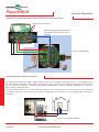
AquaHeat
Installation
Guide
Control System
A better
approach to
radiant Heating
systems
Radiant Heating and Snowmelting products
www.ComfortProSystems.com
AquaHeat
AquaHeat
Preface
System Design and Installation
The Mains
PEX pipe mains are recommended to reduce labor and architectural impact. For a slab-on-grade installation, the
mains can be buried below or within the slab. For below slab installation refer to insulated supply and returns like
ComfortPro Systems Microflex product range. For a wet or dry on plywood application, the mains can be installed
within the joist cavity. Always allow for the expansion and contraction of the mains, as the temperature fluctuates. It
is recommended that the pipe be allowed free movement and is not fastened directly to the floor joists.
Requirements of a hydronic control system
The intent of a hydronic heating control system is to achieve heating comfort, system protection, energy saving and
ease of use.
Heating comfort is achieved by:
• keeping proper system temperatures
• directing the right amount of heat when and where you want it
System protection is achieved by:
• protecting the primary heat source (e.g. boiler) from corrosion and thermal shock
• reducing equipment cycling
Energy saving is achieved by:
• running the system at the lowest water temperature possible
• turning off the system when no heat is demanded
• minimizing boiler short cycling.
Ease of use is achieved by:
• running automatic functions in lieu of manual settings
• providing easy and consistent wiring and installation procedures
AquaHeat Installation Guide Philosophy
A hydronic system can get quiet complicated and with the rapid introduction higher integrated solutions keeping
up is challenging more than ever. To keep the basic installation order we have build this guide to reflect the typical
steps in the implementation of a project:
Chapter 1 - Hydronic floor installation
2 Chapter 2 - Manifold installations
Chapter 3 - Boiler room installations
Chapter 4 - Control system installation
Chapter 5 - System start-up, warranty requirements and maintenance
www.ComfortProSystems.com
AquaHeat
Table of Contents
Chapter 4 - AquaHeat Control System
AquaHeat ProZone Control Systems
AquaHeat ProZone Control System components
4
4
Zone Definition
5
Recommended Control System per Loop count
5
Step - by - step Installation at a glance
6
General Installation Guidelines
Wiring
Component Locations
Pro Thermostat Installation Locations
7
7
7
8
AquaHeat Actuators
ProMix Manifold actuators
Actuator Operation
Mechanical Installation of ProZone Actuator
Connecting the ProZone Actuator
9
9
10
10
11
Combining the Pro Zone Master/Slave/Timer Control Box
Pro 4 and 6 Zone Master with Pump Relay Box
Pro 4 and 6 Zone Slave Box
12
13
14
15
15
16
17
18
19
21
Connecting the ProZone Transformer
23
Installing External Sensors
24
AquaHeat Thermostats
Pro Basic and “Dual Sensing” Pro Digital Dual Sensing
ProChronotherm Thermostat Features Overview
Thermostat Dimensions
Thermostat Wiring
Configuring Pro Series Thermostats for
dual sensor applications
3
www.ComfortProSystems.com
AquaHeat
AquaHeat ProZone Control System
AquaHeat ProZone Control Systems
AquaHeat ProZone control systems come in various
every application.
scalable building blocks which makes the systems suitable for
System Components are grouped into
- Actuators
- Control Box
- Timer Box
- Thermostats
- Sensors
The ComfortPro AquaHeat ProZone control system allows for various combinations of these individual components to
fit budget, size, and user convenience.
AquaHeat ProZone Control System components
4
Fig 1 - AquaHeat System Components
CHAPTER 4
www.ComfortProSystems.com
AquaHeat
AquaHeat ProZone Control System
Zone Definition
A Heating Zone is defined as an individual or grouped section of the whole heating system, which is controlled at
once.
In the simplest case a zone is characterized by a single floor loop of PEX pipe connected to a manifold. A Zone
can also comprise of several floor heating loops connected to a manifold and controlled by a single controller/thermostat. Ultimately, a Zone can comprise of a complete manifold which is controlled by a single zone valve in front
of the manifold injection loop.
Manifolds are typically operated by electro-mechanical servo motors to open and close individual floor loops water
circulation at the supply side loop valves which in turn are controlled through the ProZone control box and/or directly through thermostats.
Loop actuators can be
connected as single or
individual zones
Single loop actuator to control
a whole manifold
Fig 2 - Zone Definitions
Recommended Control System per Loop count
The ProZone heating control system can be scaled for every project. Key indicator for the requirements of a floor
heating system is the number of PEX pipe floor heating loops used in the project.
Examples are:
1. Simple, one zone system
A very basic system comprises of a manifold like the AquaHeat ProMix or ProLock manifold with one or more floor
PEX pipe loops combined to a single zone. In this case, the floor heating system can be controlled by a single thermostat like AquaHeat Pro Basic thermostat. One actuator is controlled by the thermostat and regulates the flow of
heat into the manifold loops through a zone valve in front of the manifold supply line.
2. Multiple Zone System
For a multiple zone system each zone is controlled by a thermostat and/or a ProZone control box. In this case, the
actuators mounted to the manifold are grouped to its individual zone and typically connected to a ProZone control
box. The ProZone control box allows for a clean installation without extensive wiring. The control box connects
again the Zone to the individual thermostat.
5
3. Multiple Zone system with multiple manifolds and timer control
In larger projects it is often required to use several manifolds for many floor loops. The following considerations
should be observed:
If more than one manifold is used (based on large living area coverage or higher than usual zone division) group
manifolds according to controlled zones. Make sure that control box and actuators receive enough power to support the operation (i.e. size the supply power transformer accordingly).
www.ComfortProSystems.com
CHAPTER 4
AquaHeat
Pro Thermostats
ProZone Control Box
ProZone Control System
Radiant Heating Floor Loops
Part # 1 - 3
450008
ProBasic
•
450009
Pro Basic Dual Sensor
×
450010
Pro Digital Dual Sensor
×
450011
Pro Chronotherm
×
Pro 4 Zone Master
450003
Pro 6 Zone Master
450004
Pro 4 Zone Slave
450005
Pro 6 Zone Slave
450006
Pro Clock Timer
450007
Pro Zone Power Supply
Pro Zone Transformer
(60 VA)
• Required/recommended components
× Alternative components
450014
4
•
×
×
×
•
6
•
×
×
×
•
•
×
•
×
•
10
•
×
×
×
×
•
•
×
•
•
12
•
×
×
×
18
•
×
×
×
•
•
•
•
•
•
•
•
Table 1 - Control System Recommendation per Floor loop count
Step - by - step Installation at a glance
1. Mount all components of the system, i.e. Control Boxes, Transformer, Timer boxes, thermostats,
actuators, external sensors
2. Connect the actuators to the control box or in a simple case to the thermostats directly
3. Connect the thermostats and sensors
4. Connect the pump power cable to the Master control module
5. Connect the transformer to either thermostat or AquaHeat ProZone master control box
6. After completed electrical wiring power-up the system
7. Check whether all zones are opening the actuators and the injection loop starts pumping
6
8. Program the ProZone Timer Box (if available) for desired duty cycles and night reduction.
9. Set thermostats minimum and maximum temperature range
10. Calibrate thermostats for exact temperature
CHAPTER 4
www.ComfortProSystems.com
AquaHeat
Installation Instructions
General Installation Guidelines
These step - by - step instructions explain the full installation for the ProZone Control System. Before an installation can occur the
following general guidelines and pre-requisites have to be maintained:
Wiring
Wiring of the system is divided into two groups of wires needed for the operation of the system. ComfortPro recommends using the
following minimum wire diameters as defined by the American Wire Guide (AWG):
Thermostat wiring
Table 2 - Wire Sizes
Thermostat
AWG
Diameter
Pro Basic (2 wire)
24
0.0201”
Pro Basic (4 wire)
18
0.0403”
Pro Digital (2 wire)
24
0.0201”
Pro Digital (4 wire)
18
0.0403”
Pro Chronotherm
15
0.0571”
Actuator Wiring
AquaHeat ProZone actuators come with a 3ft pre-sealed 2-pole cable. If the length of the cable needs to be extended use AWG size 18 or better 17 type wiring.
Control Box Power supply
For power line wiring the usual AWG sizes should be used. If the low voltage side after the transformer has to be extended to reach
the Control Box or thermostat, caution should be taken to use a strong copper cable in order to minimize power loss along a longer
wire.
Component Locations
All system components should be installed in the most reasonable distance to their connected modules. Caution
should be taken in small spaces so that the system components (like power transformers) are not overheating.
Control Boxes and Pro Clock Timer should be mounted on a DIN rail above the Manifold within 1-3ft of the manifold. There should be a power outlet to the left side of the DIN rail for most convenient installation. We recommend
the thermostat wiring sparing on top of the DIN rail. If a manifold cabinet is used it is recommended to size the
cabinet with respect to the Control boxes size.
www.ComfortProSystems.com
7
CHAPTER 4
AquaHeat
Pro Series Control System
Maximum DIN rail length or wall space used is approx. 25 inches.
4 Zone 6 1/2”
6 Zone 8 7/8”
4 Zone 6 1/2”
6 Zone 8 7/8”
6 1/2”
3 1/2”
24 1/4”
Fig 3 - ProZone Module Dimensions
Pro Series Thermostat Installation Locations
When installing thermostats in a new development the following aspects have to be taken in consideration.
Select the location of the thermostat conveniently for the user
Install thermostat on the inside walls of the building/dwelling
Install thermostat minimum 8 inches away from doors.
Thermostats should be mounted approximately 54 - 60 inches from the floor
Note: Avoid mounting thermostats close to windows, on outside walls, behind doors, close to the floor or ceiling
and other cooling or heating devices
54” - 60”
8
Minimum 8
inches
CHAPTER 4
Fig 4 - Thermostat Installation Location
www.ComfortProSystems.com
AquaHeat
ProZone Actuators
AquaHeat Actuators (P/N 450001, 2 - wire) or (P/N 450002, 4 - wire)
AquaHeat offers two kind of actuators for Promix and ProLock manifolds. AquaHeat actuators operate on 24VAC supply voltage and
can be controlled through the ProZone Control Box or directly through the thermostat. Actuators come as 2 and 4 wire models. 4
wire models include an additional end switch (black and grey cable) which can be used to control a pump. AquaHeat offers both
models to give optimal system versatility to the systems design.
Wiring Diagram - 4-wire
(Gray)
Wiring Diagram - 2-wire
Fig 5 - Actuator wiring diagrams
NC Actuators (Normally Closed)
AquaHeat actuators are operated as normally closed (NC) versions, i.e. during normal or stand-by operation the
manifold loop supply valve is closed and no water is pumped throught the loop. Upon request from either the ProZone Control box or the thermostat the actuator drives open the manifold loop supply valve and fresh heating water
is pumped through the floor loop. When the room temperature in the room or floor reaches the desired target temperature the thermostat or ProZone Control Box closes the loop supply valve through the drive of the actuator into
the NC position.
ProMix Manifold actuators
Actuator Operation
1 1/2” (38mm)
2” (51mm)
2” (51mm)
2” (50mm)
9
Fig 6 - ProZone Actuator Dimensions
www.ComfortProSystems.com
CHAPTER 4
AquaHeat
ProZone Actuators
When the thermostatic element expands, it supplies the thrust required for automatic movement of the valve. The
4-wire version is provided with an auxiliary contact for additional commands (metering, control of pump, fan or other
equipment). The actuator has a transparent window that allows to check the status of the actuator on the actuator
cover.
Mechanical Installation of the ProZone Actuator
Transparent Zone
Valve
Red
Closed
Black
Open
Fig 7 - Actuator Indicator
1. Remove handle or cap from the body valve.
2. Position the actuator and tighten the ring nut of the
actuator manually onto the body valve.
Do NOT use pipe wrenches, spanners or similar.
3. Connect electrical wiring.
Fig 8 - ProZone Actuator Mount
Important maintenance notes
Do not replace the connected cable. Opening the ProZone
actuator will cause irreparable damage to the device.
Faulty actuators must be replaced as complete units.
Warning
The actuator must not be installed below the body valve.
Technical Characteristics
10
Action Open/Close
Power supply 24 VAC (+10% / -15%)
Frequency 60 Hz
Power consumption (normal operation) 2.5 VA
Peak starting current 0.35 A x 30 sec (24V)
Initial opening (NC) or closing (NA) time (power ON) 24V
3 min
Final opening (NC) or closing (NA) time (power ON) 5 min
Actuator stroke max 3.5 mm
Valve stroke 2.5 mm
Protection class IP44 to EN60529
Electrical Protection class II
Safety (contamination level) 2
CHAPTER 4
Cable length 3ft
2-pole x 0.75 mm2
4-pole x 0.75 mm2
Operation temperature limit 32 - 122°F
Storage temperature limit -13 - 140°F
Fluid temperature limit Max 230°F
Nominal closing force (power OFF) (Closed type) 140 N
(±10%)
Auxiliary microswitch (4-wire model) max 700 mA
- 24Vac
Valve connection Threaded ring nut M30x1.5
www.ComfortProSystems.com
AquaHeat
ProZone Actuators
Connecting the ProZone Actuator
Actuators can either be connected directly to thermostats in a single zone environment or for multiple zones
we emphasize the use of the ProZone Master control box. By using a ProZone master control box one or more
actuators are being connected to a single zone at the zone connector bench. Each Zone connector bench can
connect up to 4 actuators, i.e. two cables per screw connector.
ProZone Master Module
Actuator 1
Actuator 2
brown
brown
blue
blue
Fig 9 - ProZone Actuator Connection
11
www.ComfortProSystems.com
CHAPTER 4
AquaHeat
Pro Zone Control Boxes
Combining the Pro Zone Master/Slave/Timer Control Box
Before connecting the thermostats and actuators the control boxes have to be properly connected. The following combinations and positions mounted on a DIN-rail are possible. The units snap into each other after the
Master cover is being removed.
Pro 6 Zone MASTER
+
Pro Clock TIMER
Fig 10 - ProZone Module combinations
Pro 6 Zone MASTER +
Pro 4 Zone SLAVE + Pro Clock TIMER
Pro 6 Zone MASTER +
Pro 6 Zone SLAVE
+ Pro Clock TIMER
Quick Installation Instructions for ProZone Module assemblies
1. Open ProZone Master module cover by unscrewing three screws from the
Master module cover front. Note that the fourth screw is delivered in a plastic
bag within the package.
2. Slide the male connector clips from either the Slave or the Timer box sideways
over the edge of the circuitboard. Note you can adjust the height of the male connector clamps by hand. See Fig 11.
3. Clip into the DIN rail or use screws to screw housings directly to the drywall (4
screws /module)
12
Fig 11 - ProZone Module
connectors
CHAPTER 4
www.ComfortProSystems.com
AquaHeat
Pro 4/6 Zone Master Control Box
Pro 4 and 6 Zone Master with Pump Relay Box
ProZone Master modules are the essential modules for any sophisticated control system. A Master module
provides power supply to multiple zones. On-board pump relay controls the circulator and or mixing pumps
directly. Activity in one zone is indicated by a green LED diode. The master module conveniently allows to
connect thermostats and actuators and assign zones to your projects. The Master Module comes as 4 (P/N
450003) and 6 Zone (P/N 450004) control box.
Technical Characteristics
Pro 4 Zone Master
Operating temperature
32°F - 122°F
Circuit Protection
Class I - IP20
Power supply
24 VAC +/- 10%
Output
Pump & accessories:
Relay => 2 free contact 8A 120Vac
Zones:
4 or 6independent zones => the maximum
output power of each zone depends
on thermostat connecting on this zone.
The maximum current for all connected
actuators is 2.5A
LED Zone Indicator
(green)
heating indicator shows water circulation
Pro 6 Zone Master
Fig 12 - ProZone Master Modules
LED Zone Indicator
13
Pump & Auxiliary
Connectors
Power Supply
Connector
1 Zone connection
bench
Fig 13 - ProZone Master Module PCB
www.ComfortProSystems.com
CHAPTER 4
AquaHeat
Pro 4/6 Zone Slave Control Box
Pro 4 and 6 Zone Slave Box
ProZone Slave modules allow for the Zone extension of the Master module functionality. The easy clip-in
extender provides a fast and reliable connection to the Master module. Two extension modules (P/N 450005
- 4 Zone, P/N 450006 - 6 Zone) are available if additional thermostats and actuators are needed for the system
design.
Pro 4 Zone Slave
Technical Characteristics
Operating temperature
32°F - 122°F
Protection
Clase I - IP20
Power supply
24 VAC +/- 10% 60Hz
Output
Zones:
4 or 6 independent zones => the
maximum output power of each zone
depends on the number of thermostats
connecting to this zone. The maximum
current for all connected actuators is 2.5A
LED Zone Indicator (green)
heating indicator shows water circulation
Pro 6 Zone Slave
Fig 14 - ProZone Slave Module
LED Zone indicator
Fig 15 - ProZone Slave Module PCB
14
1 Zone connection bench
Master Module
Connector
CHAPTER 4
www.ComfortProSystems.com
AquaHeat
Pro Clock Timer Box
Pro Clock Timer Box
ProZone timer box (PN 450007) features 7 day programing, 2 channels A and B, 1 user program per channel, 9 built in programs,
program graphics display, automatic or manual operation, key pad lock function for child safety, and in the event of a power
outage hours and parameters are saved . The easy clip-in extender provides a fast and reliable connection to the Master or slave
module.
Pro Clock Timer Box
Technical Characteristics
Operating temperature
Protection
IP30
Power supply
Master 4 or 6 zones
Pro Clock Timer Display
24 VAC +/- 10% 60Hz
Timer box
Mode description
Use the keys < & > in order to change the mode in the operating
menu.
1
5
32°F - 122°F
Set CLOCK Menu
Use this menu to adjust the Timer clock to the actual time.
2
3
4
1 : Operating mode menu
2 : Days of the week
3 : Time
4 : Program graphic
5 : Channel A or B
Use < / > to adjust the minutes Press
OK
Use < / > to adjust the hours Press
OK
Press
OK
Use < / > to adjust the day
IMPORTANT:
in order to control
your thermostats with the TIMER please put your thermostat in
position.
Manual REDUCED operating load
Force reduced temperature operation indefinately on
the 2 channel.
Manual COMFORT operating load
Force comfort temperature operation indefinately on
the 2 channel.
Manual AUTOMATIC operating load
The timer follows automatically the selected program according to the actual time.
www.ComfortProSystems.com
CHAPTER 4
15
AquaHeat
Pro Clock Timer Box
PROGRAM MENU :
By pressing + or - keys you select the channel ChA or ChB to the program then validate with OK button.
Use < & > to see the
other days in the program
Shows the daily program
Then press + or - to change the
program
If you select a built -in program P1 to P9 and press OK this program will be followed in the
BUILT IN PROGRAMS DESCRIPTION
P1: Morning, evening week-end
P2: Morning, midday, evening, week-end
P3: Day & week-end
P4: Evening & week-end
P5: Morning, evening (bathroom)
P6: Morning, afternoon, week-end
P7: 7h - 19h (office)
P8: 8h - 19h Saturday (shop)
P9: Week-end secondary house
mode.
Day
You can also select a user program U1 for channel A and U2 for channel B.
Hour of the curser
USER PROGRAM EDITION
The + key sets
temperature at the current blinking program hour.
The - key sets temperature at the current blinking program hour.
Use the < & > keys to slide the blinking curser position in the day and modify or
correct the program easily.
When the displayed day is correct press OK to save it and then you jump to the
following day. When you press OK on day 7 you return to the top menu.
Now once automatic operating mode
programs.
is selected, the timer will look for the channels A and B the desired
SPECIAL FUNCTION:
KEYPAD LOCK function :
Function to prevent any modifications or changes of the parameters.
16
In ,
,
, operating modes you should maintain the OK key pressed and simultaneously on the + or -
key to (Loc codE) or unlock (Un Loc) the key pad.
CHAPTER 4
www.ComfortProSystems.com
AquaHeat
Pro Series Thermostats
Selecting Thermostats
ComfortProSystems offers a wide range of Thermostat solutions which will fit your design. In order to easily
identify the combination of products for your complete Heating project please look at the following table (chpt
2-1)
Pro Basic (P/N 450008) and “Dual Sensing” (P/N 450009)
Thermostats contain a temperature dial which can be calibrated to reflect the correct room temperature. Pro
Basic Stats can drive an actuator directly through the on-board quiet triac. The Dual Sensing Thermostat PartNr. 450009 picks up the room and floor temperature to correctly control the manifold flow.
Fig 16 - ProBasic
Thermostat
Measured temperature
precision
Operating temperature
Setting temperature
range
Floor limiting temperature
range
Regulation
characteristics
Electrical Protection
Power Supply
Output
External Floor sensor
Soft version
0.2°F
32°F – 122°F (0°C - 50°C)
41°F - 86°F (5°C – 30°C)
50°F - 104°F (10°C – 40°C)
Proportional band 10min for 3.6°F
or Static differential 0.9°F
Class II - IP30
24 VAC +/- 10%
TRIAC output 24 VAC, 15 W max. ( 4 CPS ProZone
actuators)
NTC (10K Ohms) 9ft
V 1.4x
Pro Digital Dual Sensing (P/N 450010)
Pro Digital thermostats contain a display through which all interaction with the floor heating system is controlled. The functions are similar to Pro Basic thermostats and come with on-board sensor (part # 450010).
Measured temperature
precision
Operating temperature
Setting temperature range
Regulation
characteristics
Electrical Protection
Power Supply
Fig 17 - ProDigital
Thermostat
Output
External Floor sensor
0.2°F
32°F – 122°F (0°C - 50°C)
41°F - 99°F in 0.5°F increments (5°C - 37°C)
Proportional Integral regulation (adjustable, see
installation menu) Cycle: 15 minutes or
Static differential 0.5°F
Anti-short cycle: 3min in OFF, 2min in ON.
Class II - IP30
24 VAC +/- 10%
TRIAC output 24 VAC, 15 W max.
( 4 CPS ProZone actuators Part #450014 )
NTC (10K Ohms) 9ft
www.ComfortProSystems.com
17
CHAPTER 4
AquaHeat
Pro Series Thermostats
ProChronotherm (P/N 450011)
Pro Chronotherm thermostats contain an on-board clock to adjust temperature based on certain time of day.
The functions are similar to Pro Basic thermostats and come with on-board sensor.
Fig 18 - Pro Chronotherm
Thermostat
Operating temperature
Comfort / Reduction mode
setting temperature range
Daily clock programmable
32°F – 122°F (0°C - 50°C)
Weekly clock programmable
7 days with 1 hour step
Regulation
characteristics
Electrical Protection
Power Supply
Battery operated life
Output
41°F - 95°F (5°C – 35°C)
24H with 15 minutes step
Proportional band 2°K for 10min cycle
Class II - IP30
2 x AA LR06 1.5V
> 1 year (For Alkaline type)
Relay output => 1RT Free contact (8(3)A 24Vac )
18
CHAPTER 4
www.ComfortProSystems.com
AquaHeat
Pro Series Thermostats
Thermostat Features Overview
Features
Part #
On-Board
Sensor
External
Probe (Sensor)
Direct Drive
(Actuator)
Triac (24VAC)
Pro
Basic
Pro Basic
Dual Sensor
Pro Digital
Dual Sensor
Pro
Chronotherm
450008
450009
450010
450011
•
•
•
•
•
•
•
•
•
•
•
•
•
•
•
•
Relay
Day - Comfort
Mode
Selector
Night - Reduction
Duty Cycle
Heating/
Cooling
Control
Heating
•
•
Cooling
•
Clock Timer
•
Digital
Display
•
Proportional
Adjustment
(Hysteresis)
Temperature
Dial
•
•
•
•
Digital Button Control
•
Auxiliary Relay hockup (4
wire operation)
19
Table 3 - Pro Series Thermostat Features
www.ComfortProSystems.com
CHAPTER 4
AquaHeat
Thermostat Dimensions
Pro Basic (P/N 450008)/ Dual Sensor (P/N 450009)
3 1/8” (80mm)
2 3/8” (60mm)
1 1/4” (31mm)
Installation Steps (see also product
instructions in package)
1. Lift temperature dial from thermostat
2. Loosen visible screw to open thermostat
body
3. Pull connection wiring through appropriate
bottom hole (optional external sensor wiring
as well)
4. Use appropriate wall screws to afix thermostat body at desired location.
5. Connect wiring according to connector ID in
section “Thermostat Wiring”
6. Close thermostat cover by tightening screw
7. Push temperature dial on potentiometer half
moon stub
Pro Digital Dual Sensor (P/N 450010)
3 1/8” (80mm)
Installation Steps (see also product
instructions
in package)
1. Lift center rubber lid from thermostat
2. Loosen visible screw to open thermostat body
3. Pull connection wiring through appropriate bottom hole (optional external sensor wiring)
4. Use appropriate wall screws to afix thermostat
body at desired location.
5. Connect wiring according to connector ID’s in
section “Thermostat Wiring”
6. Close thermostat cover by tightening cover
screw
7. Push protective center rubber lid back onto
opening
2 3/8” (60mm)
1 1/4” (31mm)
Pro Chronotherm (P/N450011)
3 1/4” (83mm)
2 3/8” (60mm)
3 7/8” (98mm)
20
2 3/8” (60mm)
5 1/4” (135mm)
CHAPTER 4
1 1/2” (38mm)
Installation Steps (see also product
instructions
in package)
1. Open thermostat flip cover and remove battery
compartment lid
2. Loosen visible screws (2x) to open thermostat
body
3. Pull connection wiring through appropriate bottom hole (optional external sensor wiring)
4. Use appropriate wall screws to afix thermostat
body at desired location.
5. Connect wiring according to connector ID’s in
section “Thermostat Wiring”
6. Close thermostat cover by tightening cover
screw
7. Set batteries (right polarity) and close compartment cover
www.ComfortProSystems.com
AquaHeat
Pro Series Thermostats
Thermostat Wiring
All AquaHeat ProZone Control System thermostats are wired via two or four cables. Two cables are required for supply power and signaling to the thermostat and two wires are for driving the actuator directly to the actuator or through
the ProZone Box. For wiring of the thermostat the following AWG sizes are required:
Minimum AWG size 24 for thermostat signaling
Minimum AWG size 18 or lower for driving the actuators directly
For dual sensor thermostats the wiring is typically provided with the probe.
Connector #
Signal
1
Thermostat (24V)
2
Actuator (24V)
4
Grd
4
Grd
Table 4 - Pro Series Thermostat Wiring
Connecting Pro Basic Thermostats to the ProZone master/slave zone module
External Sensor Connector
21
Fig 19 - Pro Basic Wiring
www.ComfortProSystems.com
CHAPTER 4
AquaHeat
Pro Series Thermostats
Connecting Pro Digital Thermostats to the ProZone master/slave zone module
External Sensor Connector
A/B time zoning pilot wire(See ProClock
Timer Box for details). Connect either
zone A/B
Fig 20 - Pro Digital Wiring
Connecting Pro Chronotherm Thermostats
Pro Chronotherm thermostats differ slightly from Pro Basic and Pro Digital thermostat. This lies in the application for
Pro Chronotherm thermostats. These Stats are designed to give a timing feature into the application and thus allowing for a low cost alternative to ProZone Master/Timer combinations in. The Chronotherm thermostat can regulate a
boiler supply in a static boiler loop.
The timer function allows to set individual timing schemes for the thermostat to work. During the time the thermostat
is regulating the flow in the heating loop and thus manages the heat supplied to an area in which the thermostat is
controlling.
22
N
L
Fig 21 - Pro Chronotherm Wiring
CHAPTER 4
www.ComfortProSystems.com
AquaHeat
Pro Series Thermostats
Configuring Pro Series Thermostats for dual sensor applications
Dual sensor thermostats allow to regulate between two separate temperature measurements. For proper adjustment
of room and floor temperature it might become necessary to deviate from the pre-configured thermostat settings.
AquaHeat ProBasic and ProDigital Dual Sensor thermostat both are configurable for either only internal, only external
sensor or both, in which case the external (floor) sensor is used as a temperature limiter.
Pro Basic Configuration
Pro Basic Dual Sensor thermostats are configured by dip switches (configuration switch) located on the inside PC
board and are best adjusted during the installation of the thermostat. Basic adjustments as the actuator type, regulation mode (static differential/proportional, and the sensor modes).
Floor Sensor Temperature
Limitation setting screw
Configuration
Switch
Configuration Switch Selection Pro Basic
1. Select the actuator type (Choose between 2 - wire and 4 - wire
with end switch)
2. Select regulation method preferred
3. Select which sensors are to be used and whether the floor sensor should limit the measurement to the lower or higher temperature
Please see table below for available configurations
Fig 22 - Pro Basic Configuration
State
Configuration Switch
Function
1
Switch Position
2
3
4
1
Actuator NC
down
2
Actuator NO
up
3
Static Differential Regulation
down
4
Proportional Regulation
up
5
Internal (Room) Sensor only
down
down
6
External (Floor) Sensor only
down
up
7
Both Sensors - floor lower limit
up
down
8
Both Sensors - floor upper limit
up
up
Table 5 - Pro Basic Configuration Dip Switch
www.ComfortProSystems.com
CHAPTER 4
23
AquaHeat
Pro Series Thermostats
Pro Digital Configuration
Pro Digital dual sensing thermostats offer a wide variety of user configurable options. For details we refer to
the product specification sheet coming with the unit. To configure the ProDigital thermostat for multi sensor
applications the setup menu needs to be entered.
1. Press “OK” button for 5+ seconds. The setup menu occurs
2. With the + or - keys navigate to menu J6 - Regulation Options
3. Press OK button again to set or edit the preset value until the choice starts blinking
4. Set the desired value by navigating the + or - buttons
The following values are available
Air => Regulation with room sensor only (Floor limitations is activated if floor sensor connected)
Flr => Regulation with Floor (external) sensor only.(Without Floor limitations)
AF => Regulation with 2 sensors (room & External sensors). (Without Floor limitations)
5. Confirm your selection by pressing the “OK” button
6. Exit the setup menu by navigating with + or - keys to the menu item “end”. Pressing OK once more will exit the
setup menu.
Note: Please refer to the Menu options table for further menu option parameters.
Menu Option
24
Value description
J0
°C / °F temperature display selection
J1
“Hot” / “Cold” regulation mode. Select Hot for a Heater system, select Cold for a Cooling system
Cy
Proportional Integral regulation time cycle value in minutes (default: 15 minutes cycle)
bp
Proportional Integral regulation band amplitude value in degrees °C/°F (default: 2.0°C/3.6°F)
J4
“NC” or “NO” Normally closed or normally open actuators selection
J5
Select “PMP” to perform an 1 minute exercise everyday (if installation inactive during a day)
J6
choice of sensor for the regulation :
Air : Regulation with room sensor only (Floor limitations is activated if floor sensor connected)
Flr : Regulation with Floor (external) sensor only.(Without Floor limitations)
AF : Regulation with 2 sensors (room & External sensors). (Without Floor limitations)
J7
“rEG” (Proportional Integral) or “HYs” (0.3°K Hysteresis) regulation type selection
Cp
compensation value in °C/°F (default: 2.0°C/3.6°F) this parameter must be adjusted by a
professional
Ao
Air sensor offset adjustment (default: no offset). Display measured Air sensor value
Fo
Floor sensor offset adjustment (default: no offset). Display measured Floor sensor value
FL
Floor temperature LOW limitation (default: 5°C/41°F), effective only if floor sensor present
FH
Floor temperature HIGH limitation (default: 28°C/82°F) , effective only if floor sensor present
Clr
Press OK key during 5s to reset all the CPS LCD parameters to factory defaults
End
Press OK key to exit installation parameter menu and return to normal operation
Table 6 - Pro Digital Configuration Menu
CHAPTER 4
www.ComfortProSystems.com
AquaHeat
Pro Zone Transformer
Connecting the ProZone Transformer
The ProZone transformer (part # 450014) comes with 120VAC on the primary side and transforms power to 24VAC on the secondary side. The total Power output is 60VA. As a separate box it is connected to either a 4 or a 6 ProZone Master control box. In small
installations (up to 3 actuators) you might connect the transformer directly to the actuators and thermostats.
Technical Characteristics
Input Voltage
Output Voltage
Power output
120VAC
24VAC
60 VA
Fig 23 - ProZone Transformer
ProZone Transformer Limits
In a typical AquaHeat installation with Pro Zone control boxes and thermostats up to 18 AquaHeat Pro Zone actuators can be powered by a single Pro Zone Transformer. If more actuators are required for the control system either
use two or more Pro Zone Transformers in parallel or you might select an equivalent transformer with higher output
power.
Please note that any third party transformer used must cohere to the following requirements:
• Line (Input Voltage) 120VAC
• Load (Output Voltage) 24VAC
• Power Output 60 - 240 VA
• AC Frequency (output side) 60HZ
• Must be UL Class 2 or equivalent SA/CE/TUV approved not to void warranty
25
www.ComfortProSystems.com
CHAPTER 4
AquaHeat
ProStat External Sensors
Installing External Sensors
Pro Series thermostats come with or without external sensor (probe) for measuring the exact slab temperature or
floor temperature in addition to the room temperature. When installing a separate sensor it is important to maintain
a minimum separation of 18” from parallel run powerlines. When crossing powerlines cross at a 90° angle.
Technical Data
Cable Length
9 ft
Electr. Resistance
NTC 10K ohm
Warning: If sensor and cable is installed < 18” distance
to a power line signal distortions might lead to
inaccurate readings.
Fig 24 - ProZone External Sensor
Use only water-sealed sensors in in-slab installations since condensate can collect in the sensor’s slab conduit and
would otherwise corrode any unprotected sensor. A conduit is needed to install the sensor in concrete slabs. This
could be a piece of pex pipe with a closed end cap. The wall side end of the conduit must extend out of the slab.
Caution: Make sure there are no kinks or squeezes in the pipe conduit which would prevent the sensor to reach
the end of the conduit.
26
Fig 25 - External Sensor installed in concrete
slab
CHAPTER 4
Fig 26 - External Sensor installed with AquaHeat Heat transfer panels
www.ComfortProSystems.com
AquaHeat
27
www.ComfortProSystems.com
AquaHeat
ComfortPro Systems LLC
Phone: 1-800-968-8905
www.comfortprosystems.com
Radiant Heating and Snowmelting products
www.ComfortProSystems.com
AquaHeat
CPS_AQH0034____2011