1
COMDWL
Executecti
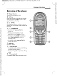
MODEL 616 AND 616B
ELECTRONIC
KEY SYSTEM
Committed to U.S. leadership in business communications
IMI 66-037
JULY, 1966
IMI 66-037
June,
1986
INSTALLATION
AND MAINTENANCE
INFORMATION
FOR THE Model 616 and 616B
ELECTRONIC KEY SYSTEMS
SERIAL
NUMBER_ _--..i .w..w...ip.+.'- i _ i i 'i.ic .~.i .e..d.dri'
iii
Introduction
IMI
66-037
CHAPTER 1
INTRODUCTION
SECTION 1
GENERAL INFORMATION
MANUAL SCOPE
This publication
contains
information
for the Model
associated
electronic
key
installation
and maintenance
616l3 and 616 electronic
key
telephone
sets.
systems
and
The installation
procedures
detailed
in this
manual,
for the most
should
be performed
by a trained
technician.
The following
part,
service
items may, however,
he performed
by any user at his or
her discretion.
All other
servicing
must be performed
by factory
authorized
personnel.
0 Place or
telephone.
l
Replace
0 Replace
Comdial
replace
the
any designation
telephone
line
or
strips
handset
on the
coiled
face
telephone
when
it
is
plugged
the
cord.
telephones
and handsets.
The handset
is
type.
Other handset
types will
not work
0 Relocate
the
system
jacks.
of
into
a special
properly.
the
proper
RELATED INFORMATION
0 IMI 01-001
Regulations
Compliance
Requirements
Part 68 and 15
0 IMI
Handling
01-005
0 GCA 70-011
User's
Of Electrostatically
To FCC Rules
and
Sensitive
Components
Guide
GENERAL DESCRIPTION
~o~f,~~,uration
---m-eThe Model 616B and 616 electronic
key systems
consist
electronic
electronic
Key Service
Unit
(KSU), dedicated
system telephone
sets
(stations),
and interconnecting
consisting
of small,
4-wire,
twisted-pair
cable.
of
an
key
wiring
This electronic
key system
is designed
to not only provide
the
economy and features
of a conventional
"lA2 type"
system but also
a much easier
installation
made possible
with
small
size wiring.
Advanced
operating
features
are made possible
by the electronic
technology
used in the KSU and the dedicated
key system telephone
set.
The system
is equipped
for a maximum of 6 lines
and 16
stations.
1
Introduction
IMI
66-037
yo+e,l, Variations
-------I-The Model 616 key system unit
has been produced
in two versions.
It is
The currently
produced
version
is designated
as 616B KSU.
an enhanced unit
which provides
standard
key system features,
adds station
pin upward compatibility
for growth,
and includes
advanced operating
features
such as expanded
toll
restriction
and
The earlier
produced
version
is
class
of service
printout
data.
designated
as 616 KSU and is currently
available
only as a
service
replacement.
Specifically,
the 616B provides
the
following
operation
enhancements:
serial
data printer
port
for
class
of service
printout;
all-call
and zone paging
through
all
system stations;
three
intercom
links;
and programmable
toll
restriction
tables.
KSU
--- Descriptipn
--------The KSU is a fully
electronic
key service
unit.
It is
essentially
a special
purpose
computer
system acting
as a
communications
controller
between TELCO or PABX supplied
lines
and proprietary
3-line
and 8-line
telephone
stations.
The KSU is contained
in a functional,
modern-style
metal housing
of contemporary
design
in keeping
with
the needs of the modern
office
enviroment.
It is engineered
to be wall or rack mounted.
Telephone
-'--w---
Set
m--
Descriptiqn
---m-m
s-s-
The telephone
set is an electronic,
microprocessor-controlled
It is designed
to allow
not only multiline
pickup
but
device:
also single
button
access to features
available
from the serving
All
stations
are equipped
with
standard
TELCO or PABX switch.
modular
jacks.
The telephone
sets are available
in 3-line
(s-button)
and 8-line
(lo-button)
handsfree
dialing
models;
3-line
and 8-line
full
speakerphone
models:
and an 8-line,
handsfree
model with a busy
lamp field.
KEY SYSTEM FEATJJRES
The electronic
key telephone
system provides
a broad range of
features.
Some of the features
are a permanent
part of the
system while
others
are programmable
as part of the system or
station
programming
procedure.
The following
paragraphs
describe
the features.
Access
-------
Denied
--MN'--
(Private
----ova--.-
Lines)
---we-
Access to particular
lines
can be denied
the system
through
system programming.
feature
is programmable
on a per line/per
2
to certain
stations
This access denied
station
basis.
in
IMI
Introduction
e{d_z!?Q Conference
I-s--.s--s-
66-037
LInternalL
--------
This system
feature
allows
the stations,
station
to
private
mode, to add another
multiline
call.
while
operating
an existing
call
in
a
or
to
a
All-call
and zone paging
allows
the system stations
to be used to
receive
or originate
one-way messages
in order
to find,
notify,
or summon someone.
A station
can be enabled
by programming
to
receive
all-call
and zone paging
messages
through
the station
speaker,
and to originate
them using
the station
handset.
A
'station
can be programmed
to only receive
messages or programmed
to originate
messages as well.
The programming
can enable
zone
paging
in up to four different
zones or system-wide,
all-call
paging.
Each station
can be programmed
to be in any or all
zones
The system defaults
for both receiving
and originating
messages.
to system-wide,
all-call
paging
in zone D with
all
stations
having
both receive
and originate
capability.
Area
---i
???ginq
Inter.face
-m-------
<.yi.,a Sp.2:~
Station
- -‘- - iv'-
Port)
- '2 - - '-
A station
port can be programmed
to interface
with
an external
It can be dial
accessed
from the other
paging
amplifier.
stations
in the system.
A line
port can also be programmed
to
This paging
interface
with an external
paging
amplifier.
amplifier
can be accessed
from the stations
in the system with
DTMF tones can be'dialed
through
the line
the line
select
key.
paging
port
to provide
zone selection
if dialed
zone selection
available
at the external
paging
amplifier.
Automatic
--'----i--
Abandoned
i---'-~i'---
Hold
i'i-i-
is
Release
-----L-i'-
If an on-hold
party
hangs up at the TELCO/PBX end of the
communications
link,
causing
an interruption
in the tip/ring
line
current,
the system will
drop the line
off of the hold condition
The line
select
indicator
will
turn
and return
i.t for service.
off to indicate
an idle
line
condition.
This feature
is
contingent
upon the availability
of a loop disconnect
feature
in
the TELCO/PBX, equipment.
Automatic
--'----s--'-
(Answer
- - - - -.-.ii' -i----'iHold
- 'i'w Transfer
- - - - - - 'd- To
-- -Intercom
If the intercom
line
active,
this
system
automatically
placed
is selected
feature
will
on hold.
while
cause
3
an outside
the outside
line
call
call
to
is
be
Introduction
IMI
66-037
A system feature
provides
automatic
privacy
on all
lines
at-every
Automatic
privacy
prevents
other
stations
from jolnlng
station.
a station
on an active
line
unless
that
station
user allows
it.
the
system
can
be
configured
so
that
certain
Through programming,
When the non-private
line
is in
lines
are normally
non-private.
m
users
of
other
stations
in
the
use at a particular
station,
This
system can join
that station
user on the non-private
line.
can be accomplished
by pressing
that
line
select
key on their
station.
An automatic
redial
of the last
dialed
number is available
at
A busy number or unanswered
call
is automatically
every station.
redialed
by this
feature.
Once automatic
redial
is selected,
the
automatically
dial
a number,
and wait
station
will
select
a line,
for a response.
It will
do this
once a minute
for approximately
10 minutes.
The user must lift
the handset
to complete
the call
voice
link.
Lifting
the handset
or pressing
any other
key will
cancel
further
automatic
redial
action.
Users of the optional
speakerphone
station
can complete
the call
voice
link
by pressing
the MONITOR
OFF key instead
of lifting
the handset.
The system will
detect
an A-lead
contact
closure
on certain
incoming
lines.
When the system detects
an A-lead
contact
closure
by an external
device
connected
to one of these lines,
it
causes a busy line
light
indication
for this
line
to appear
at
The system does not send any
all
the stations
in the system.
A-lead
signal
to the external
device
connected
to the line.
Pressing
the line
select
key on a system station
cannot
interrupt
an external
device
providing
the A-lead
closure
unless
the line
is programmed
to be non-private.
The system provides
basic,
lA2 type features.
Features
selective
line
pickup,
common line,
hold,
and multiline
and hold are available
at every station.
such as
pickup
Introduction
IMI
66-037
The system programming
is electronically
protected
during
an AC
The
power failure
by a battery-like
device
called
a "super-cap".
stored
program data will
remain
in memory for a minimum of 30
The system must
hours after
AC power fails
or is disconnected.
be powered continuously
for at least
30 minutes
prior
to the
power failure
or disconnection
for memory preservation
to occtir.
m_s.y
$_a~
-Field
- - - i
iiStation
- 'i - - - '-
:(@pt.ion)
--W-'-
There is an optionally
available
8-line
telephone
station
equipped
with
14 visual
indicators
adjacent
to the memory keys.
-This station
provides
all
of the available
features
in addition
The visual
indicators
of
to a Busy Lamp Field
(BLF) display.
this
station
display
the status
of the Direct
Station
Selection
(DSS) intercom
stations
provided
by the system at the key
locations.
Call
-..'-t
Announce
-'G~--'.G--- With
-'i'--
Handsfree
--;-i‘-'e-~.ei
Answerback
'--ii - -'-i'-'i
The internal
speaker
at each station
provides
call-announce
A handsfree
response
to a
capability
over the intercom
link.
call-announce
call
can be made. This response
is transmitted
by
the microphone
built
into
the handset.
Call
'- i - - Transfer
'A- - - i - 'i Call
transfer
allows
incoming
calls
to be transferred
from one
via
the
intercom
link,
in
one
of
two
ways.
station
to another,
If both stations
have access to the incoming
line,
a common line
If the other
station
does not
pickup
transfer
can be effected.
have access to the incoming
line,
transfer
can still
take place
Some transfer
considerations
using
the system transfer
feature.
are as follows:
If a transfer
is attempted
when there
is no call
on hold,
the station
being transferred
to will
receive
the
intercom
dial
tone,
and the transferring
station
will
he dropped
from the intercom
line.
If a transfer
is attempted
and the
station
being transferred
to does not answer the intercom
call,
the transferring
station
will
reconnect
to the call.
Common ----I-Audi,ble
-.i---Contact
closures
rings.
used to
station
contact
port
is
and Auxiliary
-c-k
mm."-'-'--'-
St.ation
-w-'-s--..
.-Interface
'~.;.- _ _ " _ ^i'
points
are available
which provide
dry relay
whenever
an incoming
line
rings
and whenever
The contact
closures
track
the ringing
pattern
When
control
an external
signalling
device.
ports
are programmed
to function
as PA ports,
They close
closures
become enable
contacts.
called
and can be used to enable
an external
5
contact
station
17
and can be
certain
these
when the PA
PA system.
Introduction
IMI
C,la_s_s_Qff_ Service
i--'--m-
?Y.ogr.amminq
--'-w--
All class
of service
10.
COS programming
maintain
the system,
Class
m---s
Of
-- Se.rv.ice
w-B----
.iFrom
--mm Main
----
66-037
StationL
--.s----
(COS) programming
is performed
from station
is used by the installer
to configure
and
line,
and station
operating
conditions.
Printout
-----i--
(Model
616R KSU)
Class of service
and toll
restriction
records
are made availableIt can be received
and
by the system as serial,
ASCII data.
printed
by any RS-232 compatible
serial
printer
which
is capable
of operating
at 110/300
baud.
Communications
are one-way to the
printer
only.
u
B_f_a,~i,_t 'ti-'-'i'-'4-i-i
Functional
Program
'ke,,;',,
At initial
power up of the system,
the operating
features
are set
to a specific
group of operating
conditions
(default
conditions).
The default
conditions
provide
a complete
operating
system
for
use.
It can be left
as a defaulted
system or reprogrammed
as
desired.
Default
conditions
can be restored,
if desired,
by
programming
action.
.~ia_linq
,,O For
-mm Att,end,ant
- - - m-v: - -i
The system
the 0 key
attendant
is dialed
station
on the
(station
intercom
10)
line.
can
be called
whenever
Di.stinctive
'i-9 - - -ii --"_ - .~,i,~.~.iis
The ringing
pattern
of an incoming
call
follows
the ringing
The ringing
pattern
of a
pattern
of the TELCO or PRX'system.
tone signalled
intercom
call
presents
two tone bursts
sounded
A voice
signalled
intercom
sounds two tone
every 4 seconds.
bursts
one time.
Do
-- 8~;
Disturb
--'-m-s.-
Any station
can be set to
key.
While
in this
mode,
incoming
call
nor will
it
a do-not-disturb
mode with
the PlOWITOR
the station
will
not ring on any
accept
an intercom
call.
Qss?/g+F_ Console
- - '- - '- i'm ,l&@b~.l
The DSS/RLF Console
is an optional
console
device
designed
to be
It is useful
with
high
a companion
to a regular
system station.
Caii
volume systems
which require
a dedicated
call
transfer
location.
The console
provides
24-key direct
station
selection
(DSS) intercom
and an associated
busy lamp field
(RLF).
It also
The
provides
one-key
access
to system-wide,
all-call
paging.
console
is designed
to be connected
to any station
port
and serve
as a companion
to the station
connected
to the adjacent
data-line
paired
port.
Installation
of this
option
to a system does not
affect
any features
currently
available
to the companion
station.
6
3
Introduction
I-MI 66-037
A faceplate
mounted volume control
on each station
can be
adjusted
to set the audio level
of the call
announce
speaker
A bottom
mounted volume control
on each station
can he
output.
adjusted
to set the audio level
of the tone ringer.
End
mi - zignal.ling
-----W-B ;Q End
-(Qff-?ook
- - - - i'i'-'-
Dia1.inq.r
------
The system can generate
DTMF tones from a dialing
station,
send
them through
the TELCO network,
and have them received
at the
distant
end for inward
call
completion
at the distant
system.
This conventional,
off-hook
dialing
mode can be performed
from
every station
in the system.
Exclusive
Hold
._
_.- ._.- ,-.-..-..-. i'i'
-i
Pressing
the HOLD key twice,
when placing
a call
on
an exclusive
hold condition.
Exclusive
hold links
to the timed hold recall
timeout
feature.
Exclusive
prohibits
the held call
from being picked
up at any
during
the programmed
timeout
period.
After
timeout,
visual
signalling
will
occur and the exclusive
hold
will
revert
to a normal
line
hold condition.
gi&.c3_ @r,eg:.t, Station
-i'a'---'- - se_@&
.~p~~~ Intercom
- -'i-is -i - with
- -'ii'
hold,
effects
the held call
hold
other
station
audible
and
condition
Answer
I, - i- m.s Hold
'-'w. ..i
Each station
comes equipped
with
a built-in
direct
station
select
intercom
for stations
12 through
25.
Access to these stations
is
effected
by pressing
the intercom
select
key and then pressing
one of the memory keys.
This action
completes
a voice
announced
Any active
outside
line
intercom
call
to the selected
station.
is automatically
placed
on hold when the intercom
select
key is
pressed.
,E,l.lsQ ,~pe.ratipn/D.ial
-.-------c---
Tone
-'i-i
Recall
-.6--'-..
When custom calling
features
are available
via a "flash"
signal,
the system can be programmed
so that
the RECALL key will
generate
a "flash"
signal
when it is pressed.
When custom calling
features
are not available,
the system can be programmed
to allow
the RECALL key to act as a positive
disconnect
or dial
tone
The
recall
key.
These two features
are mutually
exclusive.
system can be programmed
to provide
only one of these features
at
a time.
Introduction
Flexible.- -*%'-r'-ii
IMI
Rinq,ing
--- - -*
&s_.iqnment.s
S---i-
.lpel_a_yg&,
Qis_gQl;e&
66-037
S~b_&gdl
Flexible
ringing
assignments
are programmable
on a per line/per
The system can be configured
to provide
direct
station
basis.
direct
ringing
for prime
ringing
for every line
at every station;
line
with delayed
ringing
for all
other
lines;
and prime line
ringing
only.
Ringing
can be disabled
for each line
on an
Subdued ringing
is
individual
basis
at each station.
automatically
provided
to any station
that
is busy on an outside
line.
Hearing
- .-'I - w'-
512. .Co;patihl,e
---m-9
The station
handset
hearing
aids.
E Pold
w-w-
Handset
---'i-bis
compatible
with
magnetically-coupled
,a_na 5 IJ_s;e-Indic.a.t.ions
- - .m:- - - i'- i
The light
associated
with the line
indication
of the in-use
and hold
for use at a particular
station.
select
status
keys provide
of each line
a visual
available
Intercom
Tones
'A
- -'m-.- w'- Call
- - -'- Er_o_qr_e_s,s_
mm--Refer to the
(I.nte.rc.om)
,:,,,,,---L
Intercom
-i-'-'---i
Should
taking
return
Line
-'i"-
discussion
titled,
Tone
- - '- '... 0.5 y,oi,e
.Si,gna.l.linq
- - - - i'i‘
.~,i~.$e.~.~.
the intercom
line
be selected
the system will
timeout
place,
the station
to an idle
state.
with
the
no subsequent
active
status
action
and
Last
-----ms
'- -4'- i Number.
'- 'i's .s'm- R.ed.ia.1
Each station
feature
will
keypad.
It
newly dialed
number.
is equipped
with
a last
number redial
feature.
save the last
number manually
dialed
from the
will
redial
the saved number upon key command.
number will
automatically
replace
a currently
Line .P,resele,cti'o,n
-m-m
--'m--i--i---
This
A
saved
.(,Pri,m,e
.Line)
-ms---i-'-.-
If a station
is programmed
to include
a prime
line,
this
line
will
be automatically
selected
for a manual dialing
operation
when the handset
is taken off hook.
If the prime
line
is busy,
manual line
selection
must be made.
a
Auto dial
and speed dial
numbers can be programmed
to include
any
When this
is done, an auto dial
or
particular
line
desired.
speed dial
operation
automatically
selects
that
line
for dialing.
selection
must be made.
Should
that
line
be busy, manual line
(If a line
is selected
manually
for a speed dial
call,
either
station
or system,
press the HOLD/SHIFT
key before
pressing
the
8
Introduction
speed dial
key on the key
programmed
for selection
prime
line
(if programmed)
prime line
is unavailable
originate
a call
will
be
IMI
If a particular
pad.)
as part of the auto or
will
be automatically
or busy,
the last
line
chosen.
66-037
line
is not
speed dial,
the
If the
chosen.
used to
Other than the prime line
or the auto/speed
dial
line
selection,
automatic
preselection
of a line
is not part of the system.
A
line
can be manually
selected
before
lifting
the handset
(for
The key pad
handsfree
dialing)
or after
the handset
is lifted.
is automatically
set for manual dialing
when a manual line
selection
is made.
hanual
-./-'-'4'- Hold
-- -.m
A key activated
feature
at each station
will
place
a PBX or TELCO
line
on hold and provide
music to the held party
if an external
music source
is connected
to the system.
Pressing
the HOLD key once effects
a normal
timed hold condition.
Any station
which has access
to the line
can pick
up the held
call.
The normal
hold condition
will
hold a call
for a
programmed
length
of time.
At the end of the first
timeout
period,
the line
select
indicator
will
flutter
rapidly
at all
stations
and three
quick
tone bursts
will
sound at the holding
station.
At the end of each subsequent
timeout
period,
the
holding
station
receives
an additional
three
quick
tone bursts.
Each station
provides
programmable
memory dialing
features
available
in a 14-key configuration.
These memory keys can he
The
programmed
to store
numbers for automatic
dialing
purposes.
stored
numbers can he up to 15-digits
in length
and can include
line
or intercom
selection,
numbers,
f's,
*, pauses,
and flash
signals.
A pause is stored
each time the HOLD key is pressed,
and a flash
signal
is stored
each time the RECALL key is pressed.
The pause and flash
intervals
are programmable.
Alternately,
memory location
14 can provide
automatic,
repetitive
dialing
of
the last
number dialed
if a memory number is not stored
at that
location.
I
Each station
can be programmed
to provide
10 speed dial
numbers
Speed dial
numbers can be up to 15-digits
in
at the keypad keys.
length
and also can include
line
or intercom
selection,
numbers,
In addition
to the station
speed
#'s,
"'s,
pauses,
and flashes.
dial
numbers,
10 system-wide
speed dial
numbers are available
at
The
system
speed
dial
numbers
can
be
up
to
31
the keypad keys.
digits
in length,
and can include
the same information
as
described
above.
System speed dial
programming
can only be done
at station
10.
Introduction
!$&.a,
IMI
66-037
Station - - s&ac.i.ti.es
---.viw.'i'-r'i-'-
The system will
support
These stations
stations.
speakerphones.
a mixture
of 3-line
and S-line
can he standard
stations
or
Modu.lar
--mati---"- liriring
--m-S
a.nd
--- .Ja.cks/.?-Conduc.to.r
---------------sm
The system can
standard
50-pin
Station
wiring
throughout
the
be completely
interconnected
by employing
industry
connectors
and modular
plug/jack
combinations.
is small,
4-conductor,
twisted-pair
cable
Momentary
-'-'l's'- s- -.
wi;e
telephone
optional
Sy.z.s.$c
.
sytem.
,z_exs wi_tQ LED
Indicators
iv'- '-'..,i'i
- s's'- i-
The station
keys are momentary
contact,
press and release
types.
They provide
line
selection,
call
monitoring,
and other
feature
selection.
Visual
indication
of the feature
selection
is
provided
by built-in
light
emitting
diodes
(LEnsI.
Multiline
i‘--v - -i - -'- Conferencinq
.a--i-'- ----'i'This system
feature
will
allow
one or more stations
to access
two
outside
lines
at the same time resulting
in a multipath
conversation.
The voice
reception
at the distant
parties'
stations
is d.ependent
upon the quality
of the outside
lines.
If
more than one internal
station
is added to the conference,
the
voice
levels
will
be lower than when a single
internal
station
iS
involved.
Elusic-On-.Ho.ld~Mu.s.i.c
----m--m--s------
.In.t.erf.a.ce
---------
c(.E.xtern.al
- m- - - - - - Source).
m- 'i ii i:
A jack is provided
on the KSU for the connection
of a KX
This music source
places
music on TELCO
registered
music source.
and PRX lines
that are placed
on hold.
Mute
B'S"&4
Each station
transmitter
the user's
has a feature
key which will
mute the handset
or internal
microphone
(on speakerphones)
to prohibit
voic,e from being heard by the distant
party.
The night
transfer
mode automatically
transfers
the ringing
all
incoming
calls
to a particular
station
or stations
for
off-hour
or special
purpose
answering.
The night
transfer
can only be made active
from station
10.
10
of
mode
IMI
Introduction
66-037
A system can be programmed
to be a square system or a non-square
the line
1 select
key of
system
as desired.
In a square
system,
the telephone
station
selects
line
1, the line
2 key selects
line
each line
select
key selects
the
In a non-square
system,
2, etc.
available
line
specified
by COS programming.
In tenant
service,
the non-square
system provides
all
sharing
users with
the use -of
the same line
select
keys while
enabling
these keys to select
different
assigned
lines.
"Every station
can provide
on-hook
manual and automatic
dialing.
An internal
speaker
monitors
the placed
call
for completion.
handset
must be taken off-hook
to provide
the voice
link
on
nonspeakerphone
stations.
.g_r.&b-mt.ir?q
..-m-m’-
The
.@I;.$$.
The ability
to originate
calls
on certain
available
lines
can be
denied
at certain
stations
through
system programming.
The
originating
denied
feature
is programmed
on a per station/per
Originating
denied
does not prevent
a user from
line
basis.
answering
a ringing
line.
iPBX/Centrex/,Central
'i .-._.- i.i.i~ -..- _ _ _ ,-".- ,- .~_ gE.fic.e,
Comeatib.le
M-44 -m---s
The system
features
and programmable
options
are compatible
with
the requirements
of PBX, CENTREX, and Central
Office
operation.
Numbers,
#Is,
*Is,
and programmable
pauses can be made a part of
every stored
number for automatic
and speed dial.
Additionally,
a custom calling
features
access/dial
tone recall
feature
is
available
to provide
a programmable
time interval
"'flash"
signal
for custom calling
features
access or a line
disconnect
for dial
tone recall.
The station
hookswitch
also provides
a line
This feature
will
provide
dial
disconnect
when it is actuated.
tone recall
on stations
with
a programmed
prime
line.
A special
voice
pair
is available
for connecting
a non-electronic
This voice
telephone
such as an industry
standard
model 2500.
pair
is automatically
connected
directly
to line
1 whenever
there
is an AC power failure.
Call
out and incoming
ringing
on this
power failure
station
is possible
during
the power failure
The power failure
station
will
automatically
condition.
disconnect
as soon as power is restored.
The KSU has
and monitors
a red LED which provides
an AC power
the status
of the system.
11
on indication
IMI
Introduction
g:Jge
Line
-4-S
Refer
to
E&esy
the
discussion
titled,
Line
i-'i-
66-037
Preselect
.I;1.~.~&
ii.-'- - -i - - -ion
- - ,C?r.im.e
------
Rekase
---v---
When the automatic
privacy
feature
is active,
all
other
stations
are excluded
from joining
a station
on an active
line
unless
that
station
allows
it.
The privacy
release
feature
allows
a station
user to release
automatic
privacy
so that other
stations
can be
added to an active
call.
n2g.r m-3----ammable
.Kg.ys_
Refer
discussion
g&ggr
to
the
ammed
-i’-iY-
Di.r.ec.t
- - -
A station
number at
this
key
placed
on
automatically
.&~..
-
s
-
user can
a memory
is pressed,
hold and
made
Station
-‘-i-i-
titled,
M 9
5e;l.e.c.t.
-----i
Memory
- - m'm- - - 'i - -4. D,ialiqg
cFeatures.
t -"- - s 'b-ii'
(D.S.S.),
t--w.
store
an intercom
line
selection
and a station
key location
to create
a DSS memory key.
When
an active
outside
call
is automatically
a voice
signalled
intercom
call
is
to that previously
stored
station
number.
9y.s Directory
- .mi' - i '- '6.4
Each station
is equipped
with
a pull
directory
can be used for recording
station
speed dial
numbers.
out directory.
the system speed
This
dial
and
PulselTone
Switchable.
'ii'
-..--.&i.~.~.-~.- ..* _'i _.- .-.- -..The system can be programmed
on a per line
basis
to allow
the
stations
to switch
from pulse
to DTMF tone dialing
as needed.
Alternately,
the system can be programmed
to only allow
DTMF tone
dialing.
I&.g.J.~.g
Line
--mm .P.re.ference
..-m.--'----'i
The system can be programmed
on a per station
basis
to enable
When ringing
line
preference
is enabled
ringing
line
preference.
at a station,
taking
it off-hook
will
automatically
connect
it to
an outside
line
which has audible
ringing.
A line
select
key will
not have to be pressed.
This feature
enables
a key action
to save the last
number
The same key action
will
redial
manually
dialed
from the keypad.
the saved number when it is pressed
at a later
time.
The saved
number is permanently
available
for later
use until
it is
replaced
with
a new number.
12
IMI
Introduction
66-037
s,e.J.f.~~.gmxt
its- - - - i:’
Each
station
can
execute
a self
test
when so enabled.
The optional
speakerphone
provides
operation
of all
features
except
voice
signalled
intercom
calls
with the handset
on-hook.
The handset
must be lifted
for this
one purpose.
uRefer
to
the
discussion
~&.Q
f!Q.ia, .ZE,.C1.L
titled,
Memory
-
,Dialing
- - - - ii'
-Fe.atures
- ,'~;-ii-~l
The system programming
selects
the timeout
period
for a call
on
hold.
When a held call
exceeds
the timeout
period,
the system
audibly
signals
the condition
to the station
that placed
the call
The
on hold.
It also visually
signals
all other
stations.
audible
signal
is repeated
at the end of each time out period.
The visual
indication
continues
until
the held call
is picked
up.
Toll
Restriction
- '- i- '4 '--'-'-mu..--'---
-- 0- 'B'-'i
and i1
(Model
616 KSU)
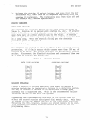
System programming
can be configured
to prohibit
some or all
any number prefixed
with
stations
from calling,
on certain
lines,
a 1 or a 0.
The feature
works as follows:
Each line
can be
programmed
to be either
a restricted
or a non-restricted
TELCO or
PBX line.
Each station
can he programmed
so that
it cannot
dial
This programming
does
a 1, a 0, or both on any restricted
line.
not prevent
that
station
from dialing
1 and/or
0 on a
non-restricted
line.
Numbers such as l-800-xxx-xxxx
are not
restricted
in any manner.
When the station
is restricted
from
dialing
1, it is also restricted
from dialing
411 on a TELCO line
or PBX line.
On PBX lines,
the 1 and 0 dialing
restriction
is
activated
after
the single
digit
access code has been dialed.
Dialing
a restricted
number on a restricted
line
will
cause the
line
to be automatically
disconnected
for 2 seconds.
'-Toll
- 's'4 -Restriction
.w'-'m- -'ii i'm'- 'i- -Exg,anded
- -*-'i - -
(Model
616B KSU)
System toll
call
restriction
can be configured,
by Class Of
to prohibit
some or all
stations
from
Service
programming,
calling
a wide range of number combinations.
The restricted
numbers are specified
on programmable
restricted
number tables
which are assigned
on a per station
and per line
basis.
toll
restriction
In general,
tables
of restricted
numbers
each.
Each table
of restricted
an "allowt'
table
or a "deny"
override
entries
in a "deny"
exceptions
to toll
restriction
works as follows:
The programmable
contain
entries
of up to 16 digits
numbers can be programmed
to be
table.
Entries
in an "allow"
table
This feature
allows,
table.
to be enabled.
For example,
the
13
Introduction
IMI
66-037
dialing
of all
l-xxx-xxx-xxxx
numbers can be denied
while
the
dialing
of l-800-xxx-xxxx
numbers
is enabled.
A "match anything"
The
symbol
(#) can be stored
to represent
any digit
from 1 to 0.
programmed
toll
restriction
tables
are individually
assigned
to
each station
and line
through
COS programming.
When a line
selection
is made and a station
is dialed,
the system
examines
the dialed
number and makes a comparison
between the
station
toll
restriction
tables
and the line
toll
restriction
tables.
Any tables
assigned
to BOTH the station
being used and
the selected
line
determine
the toll
restrictions
to be imposed.
Dialing
a restricted
number on a restricted
line
from a
restricted
station
will
cause the line
to be automatically
disconnected
for 2 seconds.
.~_o,nf ,o; ----w
Vo.ice
~&nal.ling
---r--i
-(.I.nt.ercom)
- -i i'mi i's'..
The intercom
feature
links
the stations
of the system
together.
Three intercom
paths
are available
on the Model 616B KSU, and two
paths are available
on the Model 616 KSU.
Intercom
calls
can be
tone signalled
or voice
announced
as desired,
and can be
responded
to in a handsfree
manner.
Intercom
call
progress
is
A visual
indication
is presented
marked by special
tone signals.
when all of the paths are busy.
A special
adapter
mounted on a wall.
is
Refer to the discussion
Station
.-..&..- .-..-..-..- z.Qe.a.kers)-..
i - '--- i 'v.- -
available
which
titled,
will
All.%.a.ll
i-.m-----
allow
a station
to
.;a~$ z.g$.s p~.$$$!.g .(.Yia
-w-s
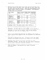
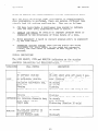
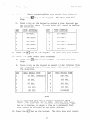
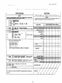
SPECIFICATIONS
The general
key system
specifications
of
are shown in Table
the
1.
14
Model
616B and 616 electronic
be
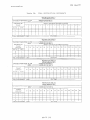
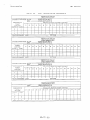
Introduction
Table
System
Capacity
Co Lines
Stations
Intercom
Paging
General
Specifications
6
16
2 (616)
3 (616B)
1 (616B)
Links
Link
Dimensions
and Weights
KSU width (inches)
height
depth
KSU pounds
Keyset
Keyset
1.
-
Power Dissipation
KSU and power supply
fully loaded system
u
66-037
IMI
footprint
pounds
@ 117VAC
nominal,
55 watts
15%
24
3%
22
7%x8%
2-10
(inches)
(lb-oz)
Cable Requirements
Station cable, 2-pair twisted, non-shielded
Maximum
cable length 1500 feet
24AWG
A-Lead Control
Loop Limits
Maximum
Resistance
of 1500 Ohms
Power Requirements
KSU and power supply
Input: 117 VAC f 10% 0.4 AMPS,
Switching
Principle
Solid state, space division,
60 Hz, single
analog
switching
phase
with
stored
program
control.
Operating
Environment
Temperature:
32-120°F
(O”-49°C)
Humidity
90% relative, noncondensing
Industry/Regulatory
Standards
FCC certified,
part 15a
FCC registered,
part 68
UL Listed (in process)
EIA RS478, Bell Pub 48002 guidance
Hearing
aid compatible
Termination
Individual,
for Outside
Lines 623 - type, four-conductor
Termination
for Stations
25-pair connector
for connection
Central Office Limits Maximum
1900 OHMS
CO/PBX
Line
REN 0.38
Ringer
loop,
Equivalence
FCC Registriation
Number
CVW7WC-12829-KF-E
minijacks:
to external
minimum
Number
15,000
USOC’s
distribution
OHMS
RJlIC
field.
cable
insulation
-
-
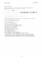
Printer Port (Model 616B KSU Only)
Format: Serial, pseudo RS-232C
(transmit
only)
Parity: None
Data Bits: 7
Stop Bits: 2
Baud Rate: 300/l 10 COS programmable
Handshaking
Requirements:
CTS (if available)
from printer to KSU
RTS (if needed)
from KSU to printer
Printer Cable Length: 50 feet maximum
from KSU to printer
15
(or RJl2C
leakage.
with A/Al leads
for lines 5 or 6).
Introduction
IMI
SECTION
66-037
2
INSTALLER/USER
INFORMATION
REGARDING FCC RULES AND REGULATIONS
This electronic
key system complies
Commission
(FCC) Rules,
Part 68.
with
Federal
Communications
The FCC registration
label
on the KSLJ contains
the FCC
registration
number,
the ringer
equivalence
number,
the
number,
and the serial
number or production
date of the
NOTIFICATION
model
system.
TO TELEPHONE COMPANY
Unless
the telephone
operating
company provides
and installs
the
system,
the telephone
operating
company must be notified
before
a
connection
is made.
The lines
(telephone
numbers)
involved,
the
and the ringer
equivalence
must be
FCC registration
number,
provided
to the telephone
company.
The FCC registration
number
and the ringer
equivalence
number of this
equipment
are provided
on the label
attached
to the KSU.
The user is
disconnection
occurs.
COMPATIBILITY
required
of this
to notify
equipment
the telephone
company when final
from the telephone
company line
WITH TELEPHONE NETWORK
the telephone
operating
company provides
When necessary,
information
on the maximum number of telephones
or ringers
that
as well
as any other
applicable
can be connected
to one line,
technical
information.
The telephone
operating
company can
temporarily
discontinue
service
and make changes which could
affect
the operation
of your equipment.
They must,
however,
provide
adequate
notice,
in writing,
of any future
equipment
changes that would make the system
incompatible.
INSTALLATION
REQUIREMENTS
Connection
of the electronic
key system to the telephone
lines
must be through
universal
service
order
code (USOC) outlet
jacks
supplied
by the telephone
operating
company.
If the installation
ask the telephone
company
site
does not have the proper
outlets,
business
office
to install
new outlets
or adapters
for the
present
ones.
The correct
outlet
jacks
for this
system are type
RJllC
or RJ12C jacks.
16
IMI
Introduction
PARTY LINES
66-037
AND COIN LINES
Local telephone
company regulations
may not
by anyone except
party
lines
and coin lines
company.
permit
connections
to
the telephone
operating
TROUBLESHOOTING
If a service
problem
occurs,
first
try to determine
if the trouble
is in the on-site
system or in the telephone
company equipment.
Disconnect
all
equipment
not owned by the telephone
company.
If
the faulty
equipment
must not be
this
corrects
the problem,
reconnected
to the telephone
line
until
the problem
has been
Any trouble
that causes
improper
operation
of the
corrected.
telephone
network
may require
the telephone
company
to
discontinue
service
to the trouble
site
after
they notify
the user of the
reason.
REPAIR AUTHORIZATION
FCC regulations
do not permit
repair
of customer
owned equipment
by
authorized
agent and by
anyone except
the manufacturer
or their
others
who might
be authorized
by the FCC.
However,
routine
repairs
can be made according
to the maintenance
instructions
in this
publication,
provided
that
all
FCC restrictions
are obeyed.
RADIO FREQUENCY INTERFERENCE
The electronic
key system contains
incidental
radio
frequency
and used properly,
may
generating
circuitry
and, if not installed
This
cause interference
to radio
and television
reception.
equipment
has been tested
and found to comply with
the limits
for a
Class A computing
device
pursuant
to Subpart
J of Part 15 of FCC
These limits
are designed
to provide
reasonable
protection
Rules.
against
such interference
when operated
in a commercial
environment.
Operation
of this
equipment
in a residential
interference
to radio
and television
reception;
user is encouraged
to take whatever
measures
correct
the interference.
If this
reception,
on, the
or both
radio's
telephone
area
may cause
in
which
case,
may be required
the
to
equipment
does cause interference
to radio
or television
which can be determined
by turning
the equipment
off and
user is encouraged
to try to correct
the interference
by one
of the following
measures:
Reorient
the television
or
receiving
antenna.
Relocate
the KSU, the individual
and the radio
or TV with respect
to each other.
stations,
17
IMI
Introduction
66-037
If necessary,
the user should
consult
the manufacturer
or an
experienced
radio/television
technician
for additional
suggestions.
The user may find
the following
booklet
prepared
by the Federal
"HOW to Identify
and Resolve
Communications
Commission
helpful:
Radio-TV
Interference
Problems."
This booklet
is available
from the
stock
No.
20402.
Government
Printing
Office,
Washington
D.C.
004-000-00345-4.
RINGER EQUIVALENCE
NUMBER
The REN of each line
of the KSU is 0.3B.
installer
to determine
the total
REN for
the equipment.
18
The FCC requires
the
each line,
and record
it
at
IMI
Installation
66-037
CHAPTER 2
INSTALLATION
MOUNTING CONSIDERATIONS
KSU
-'iC' Mountinq
-'--i"- -'i'
The KSU cabinet
should
be attached
vertically
to any sturdy,
surface.
It may be vertically
rack mounted if desired.
It
flat,
must be located
within
6 feet
of a properly
grounded,
three-wire,
117VAC, electrical
outlet.
The distance
between
the KSU and the
TELCO/PBX jacks
must be 25 feet or less as per FCC requirements.
A nominal
distance
of 7 feet
is recommended.
v
Choose a secure,
dry mounting
location
with
adequate
ventilation.
The temperature
range of the location
must be within
32-120
degrees
F (O-49 degrees
C).
If the mounting
surface
is damp or
if it is concrete
or masonry material,
a backboard
must be
attached
to the mounting
surface
to be used for KSU mounting.
Suitable
mounting
backboards
are available
commercially
or can be
constructed
out of l/2-inch
plywood
cut to size.
Tools
and hardware
required
for mounting
the KSU cabinet
include:
l/4 x l-inch
round head wood screws,
toggle
bolts,
or wall
anchors
and fasteners:
a screwdriver:
an electric
drill
if
prepared
holes
are required;
and a connecting
tool
for fastening
wires
to a type-66
connector
block.
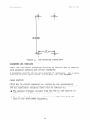
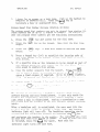
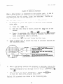
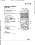
1.
A full
scale
mounting
template
is supplied
in the KSU packing
box.
Hold or tape this
template
to the mounting
surface,
and
mark the location
of the mounting
holes on the mounting
surface
as they are located
on the template.
The KSU
mounting
dimensions
are as shown on Figure
1.
2.
Drill
holes
accommodate
these holes
as dictated
3.
Attach
the KSU to the mounting
surface
with
four
(4) screws
installed,through
the KSU mounting
flange
and into
the
Note that
the flange
holes
are
mounting
surface
holes.
This
elongated
with
an enlargement
at one end of the hole.
feature
allows
the mounting
screws
to be partially
installed
in the mounting
surface
before
the KSU is hung on them.
in the mounting
surface
of a proper
size to
the hardware
being used.
If necessary,
prepare
with
inserts,
anchors
or other
attachment
devices
by the type of mounting
surface.
19
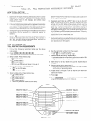
Installation
IMI
10
INCHES
I
I
Figure
66-037
1.
KSU Mounting
Dimensions
Tele&?h,o_n$
ge;t, Mount
.ti-i - -i b-q
i‘i
'* i
Place the individual
telephone
stations
as desired
with
accepted
industry
and office
standards.
and in
keeping
A telephone
station
can be wall
mounted if necessary.
Use a wall
mounting
bracket
(part
number 701032-056)
for this
purpose.
CABLE ROUTING
Cable may be routed
location
requires.
and all
applicable
concealed
or visible
as the installation
Good engineering
practices
must be observed
building
codes must be adhered
to.
@ The maximum distance
allowed
from the
1500 feet
using
#24 gauge,
twisted-pair
0 The allowed
jack to the
tip/ring
loop resistance
TELCO/PARX equipment.
20
KSU to the
cable.
is
station
1900 ohms from
is
the
Installation
IMI
66-037
CONNECTIONS
Line
-m-w iC.o.n.n.e.ct.ions
- - m- ..'v -'--k-G
Connection
four-wire
length
of
above.
A-Lead
between the KSU and the TELCO or PABX line
is via
The maximum
cable and modular
plug/jack
connection.
a line
cable
is determined
by the limitations
detailed
-
Control
The KSU inputs
of TELCO lines
5 and 6 are configured
to detect
an
A-lead
(A and Al) control
signal
when it is applied
at the TELCO
input
to the KSU.
A typical
use of A-lead
control
signal
detection
would find
a single-line,
non-key
system,
telephone
set,
modem, data terminal,
etc.
configured
for A-lead
control
and
connected
to the line
ahead of the KSU.
When the KSIJ detects
an
A-lead
control
signal
on line
5 or 6, it causes a busy indication
to be shown at all
key system stations
connected
to the line.
Pressing
the line
select
key on a station
cannot
interrupt
the
externally
connected
A-lead
device
unless
the system
is
programmed
to make the line
non-private.
The A-lead
loop
resistance
must not exceed 1500 ohms.
The A-lead
control
connections
- 43 (line
5) and 47 - 48 (line
that
is connected
to 52 of the
$a~.en,
are available
at clip
terminals
42
6) on the station
connector
block
KSU.
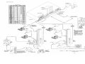
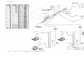
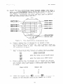
Connections
.i.- ._.-.- _'- ._.-".&.-.
Connections
between the KSU and the stations
are typically
via
two 66M-xx station
distribution
connector
blocks
per the
discussion
steps given below.
Refer to Figures
3 and 4 for
connection
details.
Various
types of station
distribution
connector
blocks
are available
and may be used in lieu
of the
type 66M-xx connector
if desired.
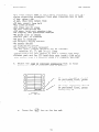
IMPORTANT NOTE
THE SYSTEM PROVIDES ONE TIP AND RING PAIR CONNECTED TO
LINE 1 AS AN EMERGENCY, POWER FAILURE CIRCIJIT.
THIS
POWER FAILURE PAIR IS LOCATED AS DETAILED ON FIGURE 3
AND 4.
THE POWER FAILURE PAIR IS ONLY ACTIVE DURING A
POWER FAILURE.
AN INDUSTRY STANDARD, SINGLE-LINE
TELEPHONE, SUCH AS A TYPE 2500, CAN BE CONNECTED TO
THIS PAIR AND USED TO PROVIDE COMMUNICATIONS CAPABILITY
SHOULD THE AC POWER TO THE SYSTEM BE INTERRUPTED.
1.
Connect
a cable
between
on the 66M-xx connecting
the KSU connector
block.
2.
Connect
four-wire,
twisted-pair
cables
from the
directly
to the station
or from the 66M-xx block
RJ14 configuration
station
jacks.
21
and the
connector
66M-xx block
to modular
IMI
Installation
66-037
The polarity
between
the individual
wires
in a
particular
voice
or data pair
is not critical;
however,
do not connect
the voice
circuits
to the data circuits.
Doing so will
make a pair
of stations
inoperative.
3.
After
making
the wiring
connections
discussed
above
illustrated
in Figures
2, 3 and 4, double
check all
connections
and cable
routing
to insure
accuracy.
.
and
Whena serial
data printer
is used for COS printout,
connect
it to
Transmitted
clips
41, 42 43, and 44 of station
connector
block
Jl.
request-to
send, and clear-to-send
terminations
data,
signal
ground,
Signal
levels
meet
are supplied
at the connector
block
by the KSU.
RS-232 specifications.
A typical
connection
configuration
is as
The maximum distance
between the printer
illustrated
in Figure
3.
When preparing
a cable
for
and the KSU must not exceed 50 feet.
connection
to the printer
interface
connector,
refer
to the
manufacturer's
manual applicable
to the printer
being
interfaced,
and make the following
wiring
connections:
0 Wire the TD line
printer
receive
0 Wire the SG line
ground pin.
e Wire
clip
the
43)
(data to printer
data input
pin.
(signal
from
ground
- clip
RTS line
(status
signal
from
to the printer
data-set-ready
0 Wire the CTS line
(status
from
printer
request-to-send
output
printer
pin.
KSU - clip
41)
42)
printer
to
the
the KSIJ to the
input
pin.
to
KSU
-
clip
to
the
signal
printer
44)
to
the
Configure
the printer,
per the manufacturer's
instructions,
to
receive
7-hit
serial
data with
2 stop bits
and no parity
bit.
Set
the baud rate
for the serial
data at 110 or 300 baud.
The printer
baud rate setting
must match the system baud rate set by COS
programming.
The system defaults
to a baud rate of 110.
22
Installation
IMI
66-037
To apply AC power to the KSU, connect
the AC power cord to a
properly
grounded,
three-wire,
117VAC electrical
outlet.
A
plug-in,
power line
surge protector
should
be installed
between
the KSU power cord and the AC outlet.
Many different
models of
surge protectors
are commercially
available
for this
purpose.
_
It is recommended
that
a grounding
wire,
separate
from the three
wire AC line
cord,
be used.
Some local
codes may require
this
use. A ground stud is located
at the lower
right
corner
of the
KSU for this
purpose.
Wire a #lO or #12, insulated,
solid
copper
wire between this
ground stud and a reliable
earth
ground such as
a metal
cold water pipe or a building
frame ground.
Two sets of connection
points
are available
which provide
relay
contact
closures
for external
use.
One set provides
a relay
contact
closure
whenever
any of the TELCO lines,
connected
to the
KSU, ring.
The other
set provides
a relay
contact
closure
whenever
system station
17 rings.
The provided
contact
closures
track
the ringing
pattern
in both cases.
The contacts
are closed
during
the ring on period
and are open during
the silent
period.
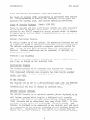
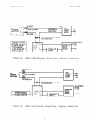
A typical
connection
to these terminals
is illustrated
in Figure
2a (model 616R) and Figure
2b (model 616).
The function
of these
control
terminals
can be changed by system programming.
Refer to
the paragraph
headed Dia.1 Access Puh1i.c ,A<$.~.~~ ;Cpfi-, Port
ii ^i i for a
discussion
of the alt~f~a~~"2unct.~6~19'
0 On Model 616B systems,
the contact
points
are clip
terminals
45 - 46 (common audible)
and 47 - 48 (station
17 audible)
located
on the station
connector
block
that
is connected
to
on the KSU.
Jl
0 On Model 616 systems,
the contact
points
- 2 (common audible)
and 3 - 4 (station
the KSU screw-type
terminal
strip.
1
on
are screw
17 audible)
terminals
located
Do not exceed a 0.4 amps at 24 volts
load on these
connection
points.
If the load requirements
exceed
this
limit,
connect
the load through
an external
relay.
DO NOT CONNECT THE CONTACTS DIRECTLY TO THE 117VAC
LINE.
23
IMI
Installation
CLIP TERM
l----1
+
\ t-l--
I
I :NST”ERNAL
‘.
24V@
0.4A
66-037
LOW
VOLTAGE
- -.. -POWfLK
SUPPLY
OUTPUT AS
REQUIRED BY
RELAY COIL
MAX
’
A
1 1
\ I
Y
AC
-----
1
P-t
VOLTAGE
CLAMPING
RECOMMENDED
DIODE
C INPUT
Figure
2a.
Model
EXT.TERM.l
KSU
INTERNAL
SWITCHING
616B External
S ignalling
- Typical
Connection
or3
1
t--H
VOLTAGE
CLAMPING
RECOMMENDED
DIODE
INPUT
Figure
2b.
Model
616 External
Signalling
24
- Typical
Connection
Installation
&$ial.
&g$.s,z
IMI
$&&
Ad.d.r.es.s+.
-cc---
.&-es
66-037
Em&
@% ~QG&
&&&QQ
QQJ&, can be programmed
to he a PA station
port
instead
of a telephone
station
(see Chapter
4, Section
2 for
programming
details).
When this
is done, the audio
input
of a PA
amplifier
can be connected
to this
station
connection
audio pair
as illustrated
in Figure
5.
The connection
must be isolated
with
a 600 ohm to 600 ohm audio matching
transformer.
Terminate
the
audio input
of the PA amplifier
with a 620 ohm (nominal
value)
resistor.
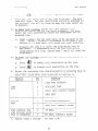
0 If station
23 is enabled
as a PA station,
the Common Audible
* connection
points
are automatically
reconfigured
as PA enable
terminals.
The relay
contact
closure
on these terminals
occurs
when PA station
23 is dialed.
The normal
common audible
function,
as discussed
previously,
is disabled
as long as
station
23 is a PA station.
l
If station
25 is enabled
as a PA station,
the Station
17
Audible
connection
points
are automatically
reconfigured
as PA
enable
terminals.
The relay
contact
closure
on these terminals
occurs
when PA station
25 is dialed.
The normal
station
17
audible
function,
as discussed
previously,
is disabled
as long
as station
25 is a PA station.
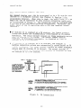
600~~ TO600n(i:i)
PA SYSTEl ml
h
AUDIO
TRANSFORMER
0
TO KSU STATION
PORT 23 OR 25 IF
ENABLE IS REQUIRED
OR TO ANY UNUSED
STATION
PORT IF
ENA-’
- .NO1 nL
FOR
MODEL
616B
FOR
KDEL
Figure
AUDIO INPUT
TO KSU EXTERNAL
CONTROL
CONNECTION
POINTS
ON 66M-XX CONNECTOR
BLOCK.
l
CLIPS 45 & 46 FOR STATION
PORT 23 PA ENABLE
l
CLIPS 47 & 48 FOR STATION
PORT 25 PA ENABLE
TO KSU EXTERNAL
CONTROL
CONNECTION
ON THE SCREW-TYPE
TERMINALS.
l
TERMINALS
1 & 2 FOR STATION
PORT 23
. TERMINALS
3 & 4 FOR STATION
PORT 25
5.
PA Connections
27
POINTS
Installation
IMI
66-037
A line
port can be configured
by Class Of Service
(COS)
programming
(see Chapter
4) to be an AUXILIARY
port.
As an
it can be used to couple
a station
voice
path to
AUXILIARY
port,
an external
device.
This is done from any allowed
station
by
pressing
the proper
line
select
key to select
the AUXILIARY
port.
DTMF tones or dial
pulses
can be sent through
the auxiliary
portas needed.
If direct
access area paging
is to be part of the system,
connect
the audio
input
of a paging
amplifier
to the KSU line
jack
programmed
to be an AUXILIARY
port.
The input
impedance
of this
The connection
must be isolated
port
is approximately
600 ohms.
with a 600-600 ohm audio matching
transformer.
Terminate
the
audio input
of the paging
amplifier
with a 620 ohm (nominal
value)
resistor.
A tone select,
zone-paging
amplifier
can be
employed
if desired.
If used, the zone-select
code must be
dialed
after
the AUXILIARY
port
line
key is pressed.
If music on hold is to be part of the system
connect
a KX
registered
music
source
to the KSTJ input
jack
(phono jack)
provided
for this
purpose.
The impedance
of this
input
is
Level
adjustment
of the music source
approximately
500 ohms.
be necessary.
This may be done during
system checkout.
An optional
station
is available
which is equipped
with
Up to eight
BLF stations
station
Rusy Lamp Field
(BLF).
connected
to the system.
A BLF station
can be connected
odd or even station
port
in the system per the following
guidelines.
@ The installed
distance
between the
be limited
to 1000 feet or less.
KSU and the
may
a 14
can be
to any
RLF station
must
@ The data-line
paired
station
port cannot
be used as a BLF
station
connection
or as a regular
station
connection.
Data-line
pa'iring
is: 10-11,
12-13,
14-15,
16-17,
18-19,
19-21,
22-24,
and 23-25.
0 The overload
paired
station
port cannot
be used
station
connection
but can be used as a regular
connection.
Overload
pairing
is:
10-12,
11-13,
18-20,
19-21,
22-24,
and 23-25.
A port,
paired
in either
as a PA port
if desired.
manner
with
28
a BLF station,
as a BLF
station
14-16,
15-17,
can
be used
IMI
Installation
.r$S~g&F
66-037
Console
- - -'-'-UC -
The optional
DSS/BLF console
may be installed
at any station
port
to work in conjunction
with a companion
system
station
connected
to the adjacent
port
(e.g.;
port
10 for station
and port
11 for
The
installed
distance
limit
between
the
KSU
and
the
console).
console
is the same as that
specified
for the companion
station.
Connect
all
four wires
(voice
pair
and data pair)
of the console
cable
to the station
connection
block.
The voice
pair
connections
of the console
can he used
simultaneously
to enable
a PA port
function.
Refer to the
paragraph
in this
chapter
headed Dial $c_$ie;g2 $&$
eddress. Port,
Per that ~-?~,~,s;~~~
and to the illustration
shown in F?Gcre 5.
wire a PA amplifier
input
to the DSS/BLF console
voice-pair
at
the station
connector
block
clip
terminals.
1Jse an audio
matching
transformer,
as discussed
in the referenced
paragraph
and illustration,
to provide
isolation.
If an enable
signal
is
required
with
the particular
PA equipment
being used, the console
and PA equipment
connections
are limited
to the station
ports
specified
in the above mentioned
reference.
The DSS/BLF console
port must be programmed
as a DSS/BLF port
(see Chapter
4 for programming
details)
before
console
operation
The console
port must be also programmed
as a PA
can take place.
port
if a PA amplifier
has been connected
to the voice
pair
as
part
of the system.
CHECKOUT
.xn.itial
- w- 'i i '- 'k '-Condition
'- 'd'-'4i i '- ‘d
The system operating
features
are set to the system default
These conditions
provide
a basic
conditions
at initial
power up.
operating
system.
They can be altered
as described
in the
Chapter
4 Class Of Service
programming
discussion;
however,
the
system should
be initially
checked
out with the default
conditions
in place.
The system
default
conditions
are
as follows.
-All
lines
are DTMF
-Voice
signalling
attempted
first
when intercom
-1 sec. pause time
-2 sec. dial
tone recall
time
-30 sec. recall
from hold
-All
lines
private
-All
lines
are CO lines
-300 msec. held call
abandon time
-No ringing
line
preference
enabled
-No prime line
is chosen
-DSS/BLF
port
is disabled
-PA port
is disabled
-No delayed
ringing
enabled
29
call
is
made
IMI
Installation
-No access denied
-No origination
denied
-No automatic
privacy
released
-Day and night
ringing
patterns
set as follows:
-station
10, 17, and 24 all
lines
-System-wide,
all
call
paging
in zone D (616B only)
-Printer
port
set for 110 baud data rate
(616B only)
-Line
select
buttons
l-n selects
lines
l-n
(squared
Whenever the
from station
system
10 per
1.
Press
the
2.
Press
the
3.
Press
the
Check the
performing
1.
-
pairing)
default
conditions
instructions.
can be reset
button.
following
keys:@)m@)@)@)@m@)
owo button.
0
KSU and telephone
installation
the following
actions.
for
proper
operation
by
Before
any AC power is applied
to the system,
measure the
resistance
across
each station
voice
and data pair.
Disconnect
the 25-pair
cables
from the KSU at the 66M-xx
Make the
connector
blocks
but leave the stations
connected.
measurements
from the blocks
(refer
to Figure
3 to identify
the connection
points
of the voice
and data pairs).
The
measured
resistance
must be as follows:
VOICE PAIR:
DATA PAIR:
Readings
possible
2.
is operating,
the following
66-037
Connect
KSU into
45 OHMS TYPICAL
45 OHMS TYPICAL
which
wiring
are
or
outside
station
(40 OHMS MIN.--150
(40 OHMS MIN.--l50
of the above
problem.
and plug
the 25-pair
cables,
the electrical
outlet.
30
the
range
OHMS MAX.)
OHMS MAX.)
indicate
AC power
plug
a
of
the
Installation
3.
IMI
66-037
Measure the voltage
across
one voice
line
and one data line
and then across
the other
voice
line
and the other
data line
Make the measurements
at the
for each even and odd station.
66M-xx blocks
(refer
to Figure
3 as needed).
The measured
voltage
must be as follows:
.
v
each
even
each
odd sta.
Readings
possible
sta.
other
wiring
I
I
than those shown
or KSU problem.
above
I
indicate
a
4.
Check the red light
emitting
diode
(LED) system status
indicator.
Be sure that
it is on steady.
If it is off or
flashing,
disconnect
and reconnect
the AC power plug.
If the
indicator
is still
not on steady,
refer
to the Failure
Analysis
Flow Chart
found in Chapter
5.
5.
Refer to the information
provided
user's
instructions
supplied
with
information.
6.
From each telephone
station,
initiate
and receive
an outside
line
and an intercom
line
call.
Be sure to set the ringer
volume to the medium or high volume setting
at each station.
7.
Exercise
every
feature
and option
individual
station.
Be sure that
and any other
indicators
function
8.
Once the basic
system
is verified
as completely
operational,
refer
to Chapter
4 and perform
the Class Of Service
programming.
31 - 32
in Chapter
3 and in the
the telephone
for operating
available
the line
properly.
at each
select
indicators
IMI
Operation
66-037
CHAPTER 3
SYSTEM OPERATION
DETAILED
SECTION
OPERATING
1
INSTRUCTIONS
This section
provides
detailed
operating
procedures
for all
station
features.
The illustration
shown in Figure
5 points
o"ut
Some
the operating
controls
and buttons
of the stations.
features
and options
illustrated
and described
herein
may not be
available
on every station
in the system.
FIXED DSS
STATION SELECTOR
LOCATIONS
do
00
--
STATION
00
00
STATTON
18 Y
19
t
MEMORY DIALING FEATURES
lling of Special Number
_. -tation Select (DSS) Intercom
l Feature Code Dialing
I
-“-
I
’
RECALL
l
Call Transfer
MEMORYKEY A14
SAVE
l Save Last Number Dialed
l Store Auto/Speed
Dial
Numbers
VOLUME CONTROL
l Adjusts Voice Volume
MUTE
l
Speed Dialing
. Last Number Redial
Pulse/Tone Switching
l
l
l
l
Speaker Off (Monitor)
End Handsfree Call
(Speakerphone Model)
DO Not Disturb
‘@KEY
l
System Speed Dial En; Ible
l
Intercom
\ITCM
HOLD
l Hold Active Calls
l Shift Pushbutton
and Key Pad Functions
l Pause storage
A 5-key telephorie set is shown for illustrative purposes.
The Executech’”
telephone set is also available as a IO-key model
for use with systems which provide 6 or 6.
linecapacity.
Both5-keyand
10.keyconfigurations are available as handsfree dialing
models and as full speakerphone
models.
Figure
5.
Full
Feature
Line Selector
RINGER CONTROL (ON BASE)
l Adjust Volume of Ringer Tone
LINE SELECTORS
l Select Line
l Enable Conferencing
. Enable Speaker For On-Hook
PULL OUT DIRECTORY
(underneath)
Dialing
NOTE:IJneSelectkeysare“Ymberedfromlefttoright.Key111b next
totheHOLOkey.Key~ilmro”gh8~whenBYaIIable)
OCC”pyan
Upper
rowwiti74tdng locatedd,reCllY
abole theHOLOkey.
Station
33
Controls
and Indicators
IMI
Operation
BASIC
ORIGINATE
A CALL
(OUTSIDE
66-037
OPERATION
LINE)
Press an unlighted
line
select
key.
When the dial
tone is heard,
The line
select
indicator
will
wink
dial
the desired
number.
slowly
at the calling
station
and be on steady
at all
other
The station
stations
when the line
select
key is pressed.
speaker
will
sound the dial
tone and the ring back or busy tone If the calling
station
is not a speakerphone,
the user
signals.
must lift
the handset
to complete
the call
when the called
party
received
or
no
answer
is
heard,
the
answers.
If a busy tone is
user must press
the ON,T,, key to end the call.
0
ANSWER A CALL (OUTSIDE LINE)
Press the line
the handset.
at the calling
stations.
select
key with
the flashing
indicator,
and lift
The indicator
changes
from flashing
to a wink off
station
and to a steady
bright
at all
other
MANUAL HOLD
Ho1.d
-w-q .A
- Cal.1
-m-d
(O,uts.ide
--i-a-~i-
Line),
-'d---m&
SHIFT
HOLD
Ask the outside
party
to wait,
and press
the L-J
key.
The
call
goes on hold and thgH,$dicator
changes to winking
at all
stations.
As soon the
key is pressed,
the user can hang
To return
to the
up or use any available
telephone
function.
Refer to the paragraph
held party,
press the line
select
key.
headed S.&A; TRANSFER
on transferring
a held
i.~i .~,-.-..i.-. for a discussion
call.
Automatic
.v--i - --d-ii
Abandpned
-i-i'U~iii"-C
Hold
..i -c
Re&ase
- - - - iii*4
If a held party
hangs up, the key system will:
wait a programmed
period
of time,
automatically
return
the holding
station
to an
This
idle condition,
and turn off the line
select
indicator.
feature
is contingent
upon the availability
of a loop disconnect
feature
in the TELCO/PRX equipment.
If the key system
is so programmed,
the line
select
indicator
will
flutter
rapidly
at all
stations
and three
quick
tones bursts
will
sound at the holding
station
when someone has been on hold
The holding
station
will
beyond a predetermined
time.
periodically
sound the three
quick
tone bursts
as long as the
call
remains
on hold.
Exclusive
'-'a-i-~-s-i-
Hold
-'s-B
SHIFT
HOLD
If the
cl
connected
to
key is pressed
the same line,
twice
and no other
stations
an exclusive
hold condition
34
a're
is
IMI
Operation
66-037
activated.
The line
select
indicator
will
be on steady
at all
other
stations
and will
wink off at the calling
station.
An
exclusive
hold will
prevent
any other
station
from accessing
the
Should
a
recall
from
hold
occur,
the
exclusive
hold
held line.
condition
will
revert
to a standard
hold condition
allowing
any
other
station
to access the line.
.
INTERCOM CALLING
Or
- - i"i - i-.-s'iginatin.g
fi .TQ.??$Zj&nalled
_ _.-,.-.,-:' Intercom
_ i.i .-.--.i -.- C&&A
1.
v
Press the
ITCM key.
the intercom
indicator
slowly.
The intercom
of the calling
dial
tone
station
will
will
sound,
wink
and
2.
Dial
the intercom
number of the desired
station.
If the
ITCM
This action
key again.
handset
is off-hook,
press the
places
the called
station
in a tone signalling
mode.
A
double
ringing
tone burst,
repeated
every 4 seconds,
will
be
Two bursts
of a ring back
heard at the station
being called.
tone will
be heard at your station
every 4 seconds.
0
3.
If handset
on the
it
party
answers,
link.
calling
station
must be lifted
is on-hook
to complete
when the called
the conversation
If the called
station
is busy on another
intercom
call,
the
If the called
station
is
system will
return
a busy tone.
the system will
return
a fast
ring
busy on an outside
call,
back tone.
The caller
may wait
for the called
party
to
answer or disconnect
by pressing
the ,,N,TO key.
e
Answering
A
Tone
s;&nalled
Intercom
$Xl,&
.~'-.'i.- .-'- .~.-_ - ';-~.-..- - '- -ii'- 'i'- .&.-4'4. ..-s4.
the user must lift
the handset
to
When the ringing
tone sounds,
answer the call.
If currently
engaged in a call
on an outside
line,
the user may disconnect
from it by pressing
the hookswitch,
or place
it on hold by pressing
the ,TCM key when the flashing
intercom
indicator
is observed.
0
.Qj.g.inat,ing
---v-v
1.
Lift
p,.v&,e
&ig.nalled
m:: -cc
Intercom
--i-c---l-i
the
handset
(even when using
and
listen
for the dial
ITCM
key,
number of the desired
station.
0
2.
The calling
station
will
user know that
the voice
speak their
message after
3.
If the called
station
is busy
will
revert
to a tone signalling
will
receive
a fast
ring back
.-Call
.i.m.&.
a speakerphone),
Dial
the
tone.
sound a single
tone burst
signalling
mode is active.
hearing
this
confirming
35
press the
intercom
to
let
They
tone.
on an outside
call,
the
mode and the calling
tone.
the
can
system
station
IMI
Operat ion
4.
If the
calling
&.gy~gi-gg
called
station
station
is busy on an intercom
receive
a busy tone.
A yo_ig$
g&.n.ab.le.d
-‘i-d--;
T.nte.rc0.m
mT--.sm--
call,
66-037
the
ga,&&
A user can respond
to a single
tone burst
followed
voice
without
lifting
the handset.
They need only
A
toward
the telephone
in a normal
tone of voice,
conversation
may continue
in this
handsfree
manner
can lift
the handset
for a private
conversation.
by
to
two
or
a caller's
speak
way
the user
-
CALL TRANSFER
$ppg
&&
Ri.c.kue
m--n-
If the incoming
line
is common to the calling
station
and to the
station
to which a transfer
is to be made, a common line
pick up
transfer
can be effected
by the station
user.
To do so, proceed
as follows:
1.
While
the call
automatically
is active,
places
the
2.
Make an intercom
call
desired,
announce
the
3.
That station
user
called
station
to
press the 0lTCM key.
call
on hold.
to the station
call,
identify
must
pick
to which
the line,
press the line
up the call.
If the called
station
does not have
line
to receive
a transferred
call,
below to transfer
a call.
select
direct
follow
This
action
a transfer
and hang
key
of
access
to the
the procedure
is
up.
the
active
detailed
0
1.
ITCM
While
the call
is active,
press the
key.
This action
Use the intercom
to
automatically
places
the call
on hold.
contact
the station
to which the transfer
is directed.
2.
The user of the called
station
must lift
the handset
to
Once the called
station
is ready
accept
a transferred
call.
key on
the caller
must press the
to receive.the
call,
RECALL
the calling
station.
The transfer
will
take place.
0
3.
If the called
the RECALL key
0
station
on the
party.
If the
The caller
up*
the held party.
MULTILINE
does
calling
not answer,
station
to
called
party
declines
can then press
the
the caller
return
to
can press
the held
the call,
they must hang
to
RECALL key to return
0
CONFERENCING
The key system will
allow
lines
at the same time.
one telephone
The resulting
36
set to access
two outside
three-way
conversation
is
IMI
Operation
referred
to as multiline
conferencing
feature,
conditions
transmission
multiline
conferencing,
following
procedure.
When using
this
conferencing.
should
be noted that
under certain
line
To enable
levels
may not be adequate.
the station
user must perform
the
it
1.
Answer
or
2.
Select
an idle
3.
Establish
the
a.
Press
and hold
the
b.
Press
the
select
C.
Release
Roth
call.
lines
are
make a call,
and place
conference
both
it
on hold.
and make a second
line,
line
66-037
line
now connected
per
line
the
following
select
key
key of
select
to
call.
the
steps:
of
first
the
second
call.
call.
keys.
the
same station
in
a conference
4.
The user can selectively
disconnect
one member of the
conference
call
while
saving
the other
by pressing
the line
select
key of the line
to be saved.
The other
line
will
automatically
be disconnected.
5.
The user may hold conferenced
The conference
call
features.
3, above.
6.
Other stations
may be added to the conference
call
by placing
the conferenced
line
on hold and then releasing
privacy.
Refer to the paragraph
titled
,&,IJP,Q.~ i.s-m.
CONFERENCINGLPRIVACY
a<.&.
.-.--.-.-,i>di--.d&..&.-..-"
&.<
REJEASE
_ _ i .- v4‘i^*efor details.
7.
End the
AUTOMATIC
conference
call
lines
can
by hanging
and use other
be re-established
telephone
per step
up.
PRIVACY
A station
can be programmed
to operate
in a normally
private
This feature
can he programmed
on a per
non-private
mode.
basis.
The system manager determines
station
features.
or
line
The private
mode, when programmed,
allows
exclusive
use of an
active
line.
No other
station
can connect
to an active
line
unless
the add-on conferencing
feature
described
below is used.
In the non-private
mode, when it is programmed,
several
stations
When
a
station
in the system can connect
to a line
at one time.
is connected
to a line,
other
stations
can also connect
to it.
Another
station
user may connect
to a line
by pressing
the line
select
key on their
station.
The resulting
conference
is
referred
to as common line
pick
up.
37
a
IMI
Operation
ADD-ON CONFERENCE/PRIVACY
RELEASE
Once a station
connects
to a line
in a private
stations
are excluded
from connecting
to it.
other
stations
to that
line
as follows:
1.
Place
invite
2.
Press and hold the
This makes the line
station
must press
3:
66-037
the call
on hold,
and use
an additional
station
to
the
join
mode,
A user
all
can
intercom
feature
the line.
other
add
to
line
select
key on the first
station.
The user of the second
non-secure.
the same line
select
key to join
the
Release
the line
select
key after
joined
the conversation
to return
condition
for both stations.
the
the
line.
other
station
has
Pine to a private
FEATURES OPERATION
LAST NUMBER REDIAL
A station
is equipped
with a last
number redial
feature,
be used to repeat
the last
number manually
dialed
from
pad.
A station
user may employ the feature
as follows:
1.
it
the
may
dial
Press the 0 F! key.
The station
will
automatically
turn on
the monitor
speaker,
select
the station
prime
line,
if
available,
or the last
active
line,
and will
dial
the last
number (up to 31 digits)
that
was dialed
from the keypad.
NOTE
2.
The keypad always
exists,
at idle,
as an automatic
line
select
speed dialer.
If a line
select
key is pressed
to select
a line,
the station
converts
the keypad to a
to avoid
the need to
manual dialing
mode.
Therefore,
manually
dial
a number after
manually
selecting
a line,
the user must convert
t2"yflkeypad
back into
a speed
dialer
by pressing
the
key.
HOLD
c3
Pick up the handset
Listen
for van answer or a busy tone.
complete
an answered
call.
terminate
a busy or unanswered
call.
to
SAVED NUMBER REDIAL
SAVE
The c3
key can be used to store
the last
number manually
dialed
from the keypad.
After
the number is dialed
and before
SAVE key
any other
numbers are dialed,
the user can press the
to cause the last
manually
dialed
number to be stored
for later
recall.
This number remains
stored
until
replaced
by another
one.
This action
can be taken while
the station
is either
on-hook
or off-hook.
To dial
using
the saved last
number
feature,
the user must do as follows:
38
IMI
Operation
66-037
SHIFT
key.
the
0SAVE
monitor
speaker;
or the last
1.
HOLD
Press the
key and immediately
press
cl
The station
will
automatically
turn on the
select
the station
prime
line,
if availahle,
active
line:
and dial
the saved number.
2.
Pick up the
Listen
for an answer or a busy tone.
Press the ONlTO key to
complete
an answered call.
e
terminate
a busy or unanswered
call.
AUTOMATIC
REDIAL
An automatic
station
user.
connected
to
resulting
in
automatically
programmed
at
the programmed
To use the
1.
2.
(OF BUSY NUMBERS)
automatic
will
-to
redial
of a busy number can be performed
by a
This feature
is available
when the station
is
a line
and a dialing
operation
has taken place
Automatic
redial
is
a busy signal
or no answer.
disabled
whenever
a memory dialing
feature
is
memory key 14 but is automatically
restored
when
feature
is cleared.
When the busy
(AUTO REDIAL).
light
active.
handset
redial
feature,
number signal
Banq up the
flash
rapidly
to
proceed
as follows:
is heard,
press
the memory
The
handset
if off hook.
indicate
that
key
0
redial
automatic
ITCM
After
a 1 minute
wait,
the system will
activate
the station
and redial
the number.
monitor
speaker,
reselect
the line,
If the handset
is not picked
up or the ONlTOkey is not
0
pressed
(because
of a continued
busy signal),
the line
will
be dropped
approximately
20 seconds
after
the number is
completely
dialed.
Automatic
redial
action
will
repeat
ten
times.
If the ringing
tone is heard,
the handset
must be
picked
up or the ON,TO key pressed
to take control
of the
e
call.
The indicator
will
stop flashing
when this
action
is
taken.
NOTE
On a speakerphone,
pressing
the
take control
of
key or by lifting
a call
either
the handset.
by
Although
a conversation
can he established
on a
speakerphone
without
taking
control
of the call
the
line
will
be disconnected
within
20 seconds
if kontrol
action
is not taken.
3.
Cancel
the automatic
redial
by lifting
and replacing
the
handset.
Any other
use of the station
while
the automatic
redial
feature
is active
will
cancel
further
automatic
redial
action.
The indicator
will
stop flashing
when automatic
redial
is cancelled.
39
14
is
Operation
IMI
AUTOMATIC AND SPEED DIALING
66-037
(STATION)
A station
is equipped
for both automatic
dialing
and speed
dialing.
These features
provide
methods by which numbers can be
retained
for easy retrieval.
Up to fourteen
15-digit
numbers in
the automatic
dial
portion
and up to ten 15-digit
numbers in the
speed dial
portion
can be stored
for retrieval.
An additional
ten 31-digit
numbers can be stored
at station
10 and used by all
stations
for system-wide
speed dialing.
In the following
paragraphs,
the method of storing
numbers for use is the same for
all
types of dialing
modes and is described
together;
however,
the way that
these
features
are used is somewhat different
and is
described
separately.
Storing
-----ms
@'J $?z~
A user
may store
'-D.ial
m-m
- 0.5 $ Speed
--li
a desired
Dial
-'d-i
Number
-ms'.e'.d--
number
as follows:
and listen
for
1.
Press
the
lTCM
c3
key,
2.
Press
the
(>SAVE
key.
3.
Press a memory key for the automatic
dial
number to be stored
or press a keypad key (1-O) for the location
code of the
A tone burst
will
sound to
speed dial
number to be stored.
confirm
this
action.
4.
If a specific
line
or intercom
is to be stored
as part of the
number,
press
the line
select
or intercom
key corresponding
to it.
A tone burst
will
confirm
this
selection.
This
action
is optional.
If a specific
line
or intercom
is not
stored,
the system will
automatically
select
the prime line
(if
available)
or the last
line
used to originate
a call
when
automatically
dialing
the number.
5.
Dial
the number sequence
as if it
A pause can be stored
by pressing
The
intercom
the
dial
dial
tone.
tone
will
stop.
were being dialed
on-line.
the SHIFT key, and a
HOLD
c3
hookswitch
flash
can be stored
by pressing
the RECALL key.
Up to 15 digits
including
the numbers,
Q'S, *Is,
pauses,
and
flashes
can be stored
at each location.
0
6.
7.
Repeat steps
2 through
5 for each desired
automatic
dial
If the memory key 14 is
number or speed dial
number.
programmed
as an automatic
dial
location,
the automatic
redial
feature
normally
controlled
by this
key is disabled.
To restore
the automatic
redial
feature,
repeat
steps
1 and
2, press key 14.
key
to
end the
procedure.
i
Operation
TM1 66-037
Automatic
.i..-..ii '&'&,&y Dia.;
,G_ _ _ C)eer.at,i.o.n
---.ev-1.
Press a memory key.
A station
monitor
speaker:
select
a line
number,
the station
prime
line,
dial
the number.
will
automatically
turn on the
(programmed
as part of the
or the last
active
line):
and
2.
Listen
for an answer or a busy
complete
an answered
call.
terminate
a busy or unanswered
tone.
1.
Pick
up the
handset
.
to
call.
Press the keypad key corresponding
to the desired
number.
station
will
automatically
turn on the monitor
speaker;
select
a line
(stored
as part of the number,
the station
or the last
active
line);
and dial
the number.
prime
line,
A
NOTE
2.
The keypad always
exists,
at idle,
as an automatic
line
select
speed dialer.
If a line
select
key is pressed
to select
a line,
the station
converts
the keypad to a
manual dialing
mode.
Therefore,
to avoid
the need to
manually
dial
a number after
manually
selecting
a line,
the user must convert
tSkflkeypad
back into a speed
dialer
by pressing
the HOLD key.
c3
Listen
for an answer or a busy tone.
Pick up the handset
complete
an answered call.
terminate
a busy or unanswered
call.
SPEED DIALING
to
(SYSTEM)
The system can have speed dial
numbers stored
which can be
accessed
by any station
in the system.
The system manager
determines
what numbers are available
with
this
feature.
The
user can employ this
feature
per the following
procedure.
1.
Press the 0*z
key on the keypad and immediately
press
the
keypad key, corresponding
to the desired
number.
A station
will
automatically
turn on the monitor
speaker;
select
a line
(stored
as part of the number,
the station
prime
line,
or the
last
active
line);
and dial
the number.
MOTE
The keypad always exists,
at idle,
as an automatic
line
select
speed dialer.
If a line
select
key is pressed
to select
a line,
the station
converts
the keypad to a
Therefore,
to avoid the need to
manual dialing
mode.
manually
dial
a number after
manually
selecting
a line,
the user must convert
the keypad back into
a speed
dialer
by pressing
the
41
Operation
2.
IMI
Pick up the
Listen
for an answer or a busy tone.
complete
an answered
call.
Press the ON,TO key to
63
terminate
a busy or unanswered
call.
~.yg_t.e.g s~,,e_e~ Di.al
-e-m
Nu.mber
-w-w
‘...q .Storag_e
-'-es-
(Station
q----l-B
2.”
Press
stops.
the
3.
Press
entry.
the
4.
Press a keypad key (1-O) to establish
the location
A tone will
sound
the first
number to be stored.
this
action.
5.
If a specific
line
or
press
the
the number,
will
sound to confirm
6.
Dial
the number sequence
from the keypad.
Press the HOLD
c3
key to store
a pause if needed,
and press theRECALL key to
1Jp to 31 digits
(numbers,
store
a flash
signal
if required.
#Is, *Is,
pauses,
and flashes)
can be stored
in this
manner.
7.
Repeat
8.
Press
key
on the
key.
SAVE
0
keypad.
A tone
the
line
this
will
intercom
select
action.
Note
sound
dial
10.
10
the
GE3x
the
from station
The station
instructions:
Press
ITCM
for
to
1.
a
and listen
handset
Only)
^i10 -at--...-
The system speed dial
numbers can only be stored
These numbers can be up to 31 digits
in length.
user can program
these numbers per the following
key
66-037
that
to
tone.
the
dial
confirm
tone
the
mode
code of
to confirm
is to he stored
as part of
A tone
keY for that line.
SHIFT
0
steps
the
ONITO
3 through
Q
OM-HOOK DIALING/LINE
key
to
6 for
each
end the
desired
speed
dial
number.
procedure.
MONITOR
The station
is essentially
a handsfree
station
which allows
A user only needs the
on-hook
dialing
and call
establishment.
handset
for originating
intercom
calls
and to complete
a voice
During
a conversation
a user
link
after
a call
is
established.
may switch
from the handset
to the call
monitor
speaker
and back
again.
After
a handsfree
call
is established,
the user must lift
the
The monitor
handset
from the cradle
to provide
a voice
link.
indicator
light
will
turn off.
The handsfree
operation
can he
reactivated
for monitoring
purposes
by pressing
the ON,TO key
e
The indicator
will
turn
and replacing
the handset
in the cradle.
To hang up when the call
on once more when this
action
is taken.
Note that
the
is finished,
press
the ON,TO key again.
Q
indicator
light
turns
off once more.
42
IF!1 66-037
Operation
DIAL
TONE RECALL/FLASH
OPERATION
It is sometimes
convenient
when making one call
right
features
are not available
can be programmed
to allow
disconnect
key.
to have a line
disconnect
key to use
When custom calling
after
another.
from the host system,
the key system
key
to
act
as
a positive
the aECALL
0
Dial
tone recall
and flash
system will
be programmed
'Flash
--'--i'-
operation
to provide
The
exclusive.
these features.
are mutually
only one of
gpe.ration
- - - - i- - i
When custom calling
features
are available
from the host system,
the instructions
for accessing
them indicate
that
the user should
first
execute
a "flash"
operation.
Each station
is equipped
with
a RECALL key which can he pressed
to cause a precisely
timed
flash
signal
to be electronically
generated.
Flash
operation
and dial
system will
be programmed
tone recall
to provide
The
exclusive.
these features.
are mutually
only one of
AREA PAGING INTERFACE
If the telephone
system
includes
the proper
external
paging
equipment,
and a station
is programmed
to enable
paging,
it can
be used to voice
address
an area of the site
in order
to find,
A user can access
this
paging
feature
notify,
or summon someone.
directly
by pressing
the proper
line
select
key and speaking
into
the handset.
If zone paging
is available,
dial
the proper
zone
code before
speaking.
Paging access may require
the use of the
intercom
and the dialing
of a 2-digit
code.
The system manager
can provide
complete
details.
ALL-CALL
AND ZONE PAGING - VIA
STATIONSPEAKERS
(MODEL 616~)
All Call
And Zone Paging
uses the station
monitor
speaker
and
handset
to receive
and originate
one-way messages.
Such messages
could
be used,to
find,
notify,
or summon someone.
With this
feature,
a station
may be programmed
to only receive
a message;
however,
it may be programmed
to originate
a message as well.
Also,
a station
may be a part of only one call
zone, a part of
The
several
call
zones,
or a part
of the system-wide
all
call.
system manager determines
the capabilities
of the stations.
Reception
of all
call
and zone paging
messages
are automatic.
If
a station
has message originating
capability,
it can be used to
announce messages to other
stations
in the system as follows:
1.
Determine
to which
zone
the
message
43
is
directed.
Operation
2. .
IMI
Lift
the handset,
keypad key which
Key@JJ) selects
Key
3:
69
Announce
press the
corresponds
zone
zone B
selects
zone C
the
and then press
zone to be called.
key
the
I
the
A
selects
R selects
system
ITCM
0
to
66-037
system-wide
all
call
(Unless
your telephone
is programmed
to provide
a zone D instead)
message,
and hang
up the
handset.
HINT: Store
the calling
location,
and use the
access to the all
call
KEY ) at a memory key
sequence
( alTCM
automatic
dial
feature
to provide
one-key
and zone paging
feature.
DIRECT
(DSS)
STATION
SELECT
INTERCOM
The system has a Fixed
DSS feature
built
into
it.
The feature
allows
a user to make a voice
signalled
intercom
call
to certain
stations
without
having
to first
store
the numbers.
With a Model
stations
12 through
25 can he called
using memory
616 system,
keys 1 through
14.
ITCM
To use Fixed
DSS, the user must press
the
and then
key,
c>
(The station
key locations
begin with the
press a memory key.
top left
location,
proceed
down that
column,
and continues
with
Any
currently
active
call
is
the top of the right
column.)
automatically
placed
on hold,
and an intercom
call
is placed
to
The type of signalling
first
attempted
is
the selected
station.
dependent
upon COS programming
but the handset
must be lifted
to
Otherwise,
enable
voice
signalling
(even with
a speakerphone).
tone signalling
is enabled.
Programmed
i's .m-'d-'-e i'-'-3 DSS
v's'<
When a user is,required
to answer and announce
a high volume of
calls,
Programmed
DSS may be advantageous
because a selection
need not be prefixed
by pressing
the ITCM
Store an intercom
key’
c3
line
selection
action
and a station
number at those memory key
to the paragraph
headed
locations
to be used for DSS. (Refer
STORING
AN.
AIJTO
DIAL,
OF,
2.
SPEED
JX5.k
2Jr_lg%.z
for
number
storing
v - -'-'es
in'..gy& tyEng,'"'"
.-- - Any
To use Programmed
DSS, simply
press a IXS memory key.
currently
active
outside
call
will
be automatically
placed
on
hold,
The type of
and an intercom
call
will
be placed.
signalling
first
attempted
is dependent
upon COS programming
but
the handset
must be lifted
to enable
a voice
signalling
(even
tone signalling
is enabled.
with a speakerphone).
Otherwise,
44
IMI
Operation
NIGHT TRAFJSFER (Station
66-037
10 Only)
The night
transfer
mode can only be set from station
10.
No
This
other
station
in the system can control
this
feature.
operating
mode is programmed
to automatically
transfer
the
ringing
of all
incoming
calls
to a particular
station
or stations
The station
10 user
for off-hour
or special
purpose
answering.
can set this
mode as follows:
ITCM
and listen
for
the
dial
tone.
1.
Press
the
3<.
Press
stops
Note that
the dial
the El F key on the keypad.
and the intercom
indicator
will
flash
rapidly.
c>
To deactivate
the
intercom
indicator
key,
night
will
transfer
turn off.
mode,
repeat
steps
tone
The
1 and 2.
DO NOT DISTURB
The user can disable
the station
ringer
by pressing
the 63NIT0
The indicator
will
remain
on steady
as a reminder
that
key once.
To re-enable
the ringer,
the user must
this
feature
is active.
press the ONITO key again.
This feature
can be activated
with
0
the handset
on or off hook.
MUTE
During
a conversation,
a user may press and hold the
Releasing
to prevent
the distant
party
from hearing.
key allows
a two-way
conversation
to resume.
PULSE/TOME
DIAL
MUTE
c3
the
key
SWITCHARLE
The method of dial
signalling
used is determined
by system
programming.
If the line
has been configured
to allow
pulse
dialing,
the initial
dialing
mode will
be pulse.
Pulse dialing
will
remain active
during
a dialing
operation
until
tone dialing
is selected
by pressing
the
key.
Once selected,
the tone
@I F
dialing
mode will
remain active
until
the station
is disconnected
from the line
(hang up occurs).
After
tone dialing
has been
selected,
the
key will
generate
a DTMF tone when pressed
@I c
again.
The cl#p
key can be pressed
during
the storing
of a
memory dialing
sequence
to cause the pulse/tone
switching
to
occur during
the automatic
dialing
of a number.
LINE
PRESELECTION
(PRIME
LINE)
The system programming
can assign
a particular
line
to a station
as a principle
or "prime"
line.
If a station
has been assigned
a
prime line,
this
line
is automatically
selected
by the station
for each call
originate
action
unless
it is already
busy.
Also
when a call
comes in on the prime line,
the user can answer it by
45
Operation
IMI
66-037
lifting
station
manually
the handset
without
pressing
the line
select
key.
If
does not have an assigned
prime line,
the user must
select
a line
before
making or receiving
a call.
RINGING
LINE
a
PREFERENCE
The system
programming
can be performed
to enable
a ringing
line
preference
feature
at a station.
an audibly
ringing
If enabled,
line
(either
outside
or intercom)
will
be automatically
answered
when the station
handset
is lifted
or the ,,N,TO key is pressed
0
on a speakerphone.
Neither
the line
select
key nor the c_)ITCM
key will
have to be pressed
to connect
to the ringing
line.
DIALING
0 FOR ATTENDANT
lTCM
When a user presses
the
cl
intercom
call
is automatically
allows
a station
user to call
dialing
familiar
method
(i.e.:
OPTIONAL
key and then presses
made to station
10.
the system attendant
0 for the operator).
the 0 key, an
This feature
using
a
FEATURES OPERATION
SPEAKERPHONE OPERATION
.C$&j.i.na.t.ing
-m-w--
4 Call
---r'-
To originate
line
and dial
a handsfree
N,T,-, key to
63
Answering.
- - P'iG - - d' 2
a speakerphone
call,
the user must select
an idle
When the called
party
answers
the desired
number.
conversation
can begin.
The user must press
the
end the call.
$Zi
To answer a speakerphone
call,
the user must press the line
select
key of the ringing
line
and speak in a normal
tone of
voice
toward
the station.
The audio volume level
is adjustable
The
with
the volume control
that
is located
on the faceplate.
user must press the ON,TOkey to end the call.
63
$t&:h_,jn_~. $er-mm.i..g3 t i.0.n se_&z-e,w~ ya,n_<s_e,t_+_I! ~paker&Q~s
m-s-from handset
a user may switch
and back again as follows:
During
a conversation
speakerphone
operation
Handset
operation
to
To Speakerphone
1.
return
the
key
handset
2.
Continue
the
speakerphone.
3.
Hang up when the
again
(note that
(note that
the
to the cradle.
conversation
call
the
in
indicator
a handsfree
turns
mode using
is finished
by pressing
indicator
turns
off).
46
the
on),
and
the
key
IMI
Operation
Speakerphone
66-037
To Handset
1.
During
a speakerphone
indicator
light
will
2.
Continue
handset.
3.
Reactivate
the speakerphone
operation
key and hanging
up the handset
(note
will
turn on once more).
xl.
Press
the
call,
lift
turn off).
conversation
in
handset
a private
the
ONITO
key again to end
Q
BUSY LAMP FIELD STATION OPERATION
An optionally
available
8-line
14 visual
indicators
adjacent
provides
all of the available
Busy Lamp Field
(BLF) display.
attendant's
station.
the
the
(note
mode using
that
the
the
*
by pressing
the 0 ONIT
that
the indicator
light
call.
telephone
station
is equipped
with
This station
to the memory keys.
system
features
in addition
to a
It is normally
connected
as the
The BLF indicators
always display
the status
which are reached via the Fixed
DSS feature
station.
No DSS programming
is required
to
indicators.
of the stations
built
into
the
activate
the BLF
BLF STATUS
The BLF indicators
use:
display
LIGHT
Station
idle
- can
Station
busy
on intercom
line
- cannot
Station
ringing
busy on outside
and the intercom
line
line
- receives
indicator
OFF
LIGHT
FLASHING
LIGHT
ON
STEADY
the
Station
in do not
but intercom
line
following
station
status
when
be signalled
disturb
indicator
47
mode - receives
flashes.
be signalled.
subdued
flashes.
no ringing
in
IMI
Operation
STATION
66-037
OPERATING CONDITIONS
VOLUME CONTROL (RINGER)
A station
user can adjust
the loudness
of the tone ringer
at a
The control
for doing
this
is located
on the bottom
of
station.
Adjust
the lever
control
toward
the center
of
the telephone
set.
the loudness
and toward
the
the telephone
housing
to increase
edge of the telephone
housing
to decrease
the loudness.
DISTINCTIVE
RINGING
(RINGING
There are four distinctive
are described
below.
PATTERNS)
ringing
Ring:
m'ii%' - The ring
patterns
pattern
in
provided
the
They
system.
1.
TELCO/PRX
---.-'G-i'4i-
3. .
Intercoy?
~"t~~'~o~~
The tone
Tone S.igna.1l.b-q:
6urstsiszunie8
every four
signalling
seconds.
ring
pattern
is
3.
Intercom.-..-.- Voice
A voice
.T*e.4.-icd
.-'-..=_ _ Sis~.al$,i.ns;,
two tone bursts
sounaea once.
signalling
ring
pattern
is
4.
Timed Hold Recall:.
The timed
-Ff-?'Fze 'CoEe 6G?%;-sounded
at
the station
that put the call
ring pattern
is
each recall
period
at
hold recall
the end of
on hold.
by the
host
system.
INTERCOM CALL PROGRESS TONES
There
are
five
intercom
tone
patterns
as follows:
1.
Inte,r,.cpm
'."---"--a
tone.
intercom
dial
tone
is
2.
Intercom
Ring
Ba,ck..:.
~~-c'-.il's'm.ks
-d*VT3
- -- The intercom
bursts
sounded every
4 seconds
ring
back
tone
3.
station
is busy on an
Intercom
Fa,st. li.in.g Back:
k&~~~~;-c~TT,
m-.-i-. When a called
cw6-tone
bursts
sounded every second is
These tone bursts
also
received
at the calling
station.
signify
that
the called
station
cannot
be voice
signalled.
4.
Voice
Ring pac.k:
signalling
is
'$pTaarkaSi.g.nallin.2.
,; ii:'*
- '- - i=i When voice
a singfg-Fone
burst
will
sound to indicate
the caller
should
proceed
with
the voice
announcement.
s.
Dial
.me-m Tpne.:.
mq--q The
a continuous
is
two
tone
that
is sounded every second
Inte.r.coorn Bus.~ .Ton.e.:
-W.--T One tone burst
.GEen-a-zai"?ed
station
is busy on an intercom
call
or does not
exist.
48
IMI
Operation
CLASS OF SERVICE
AND SPEED/AUTOMATIC
DIALING
COMFIRMATION
66-037
TONES
When the Class Of Service
(COS) programming
or speed/automatic
dial
programming
is performed,
there
are several
different
tone
They are as follows:
signals
used for program confirmation.
1.
.gp,S Base
i' - '- - &g.y.:.& $.g.g.:. A continuous
that the base level
programming
2.
An invalid
or improper
program
entry
Invalid.
COS. g$fx.:
~'?$i~?Iea"6y
one occurrence
of three
bursts
of a tone.
3.
"
E?-WJ &~~pa;.:.
gy"ijne
toneXurst.
4.
A_c.~.~~$~,_ng,D,ial.ing
.~Jg.&,~
When dialing
digits
are being
--r-k-programmed
for later
recall
by the speed and automatic
dialer,
one tone burst
is sounded as each keypad key is
pressed.
VISUAL
t
LINE
SELECT
or
correct
program
SELECT, ITCM and MONITOR indicators
the status
of a particular
line
or
indications
are described
below.
CALL STATUS
indicate
entry
is
_
is
signalled
station
channels
active
station
The
busy
Dark
On with short
wink off .every 2 sec.
Fast flash
with wink off every 2 sec.
Fast flashing
On with
long wink off every 2 sec.
On steady
On steady
Flashing
Flutter
with wink off every 2 sec.
Flashing
On with short
wink
On steady
Fast flashing
Fluttering
(Station
t
On line
and speaker
on
(microphone
also on if
speakerphone)
Do not disturb
mode
on the
feature.
INDICATION
Idle
In use-your
station
On hold-your
station
On hold-other
station
Exclusive
hold-your
station
Exclusive
hold-other
sta.
Busy line
Ringing
Recall
(held call
timeout)
Ringing
In use-your
INTERCOM All
intercom
Auto redial
Night mode
MONITOR
to
INDICATIONS
The LINE
indicate
possible
I INDICATOR
A valid
tone sounds
mode is active.
On steady
On-steady
49
off
every
10 only)
2 sec.
IMI
Operation
66-037
SECTION 2
CLASS OF SERVICE PRINTOUT
F?hen a data printer
commanded to print
configuration
for
complete
printouts
is connected
to the printer
port,
it can be
the class
of service
(COS) programming
Partial
or
the systeml
lines,
and stations.
can he obtained.
*
Use the
procedure
1.
following
At Station
10,
entry
mode.
to
place
the
lTCM
key.
obtain
system
the
in
the
COS printout.
base
level
program
0
2.
a.
Press
the
b.
Once the
keypad.
C.
Press,
kevs.
level
in sequence,
the a,the
@$,and
A tone burst
will
sound to indicate
programming
mode is entered.
d.
Press
the
a
dial
tone
is
key
Press a memory key to
the following
chart.
heard,
press
and listen
select
the
for
type
dial
of
3.
4.
KEYS
the m,keypad
that the base
tone.
printout
DRlNTnl
- KEYPAD
key on the
the
desired
IT FFATIIRE
per
I
PRINTOUT STOPS AT NEXT COS BREAKPOINT
COMPLETE
PRINTOUT
PRiNTS SYSTEM AND LINE COS PLUS TOLL
RESTRICTIONS -__-PRINTS SELECTED
STATION
COS
SELECTS STATION (10-25) FOR COS PRINTOUT
When a particular
station
COS printout
is desired,
follow
the
key operation
by pressing
k,ey.~.@ keys
memory dialing
feature
which correspond
to the desired
station
(e.g.,
press
keys
and
to select
station
12).
0 :
COS printout
will
begin immediately.
to exit
the base level
program
entry
mode.
Typical
COS printouts
are
shown
on the
50
following
page.
c
IMI
Operation
SYSTEM
COS
PWSE
1.8
SEC
PULSE
1.8 PeS
FLQSH
:36,8
MSEC
38 SEC
Tt-iR
LINE
LTNE
:l
2
3
4
ET
6
$13
TOLL
RES.
P. Q.
PRIME
C" 0.
c. cl.
c. 0.
c.0.
c. 0.
RUX
PULSE
HOLD
5QMSI
RING
RTNG
RING
kCCESS DENY
NITE
TOLL
TREiLE
ORIGIN
PRTVKY
?2'3
ia
1224
fiLL
4 56
X X X X **
x
x
X X X X X X
DENY
RLS
CALL
GROUP
x
--
Ii?:1
DELQY
TYPE
LINE
LINE
COS
PRV
RLS
STfiTION
66-037
BUTTON
LINE
NO.
RECEIVE
RBCD
x x x x
1 2 3 4 5
ORXGIN
FlbCD
x x x
x
6 7 a
i 2 3 4 5 E
L
TOLL
TQBLES
I
-!-FW-E
5
DENY
STFSTICN 1e
TCLL RES. 123
P. k.
PRIME
-‘RE:..E
E,
RING
RXNG
RING
DENY
DENY
RL-S
DELlr3Y
NXTE
F,CCESS
l2RIGIM
3 R 1 i’fiC’f
4.
DEXY
iritt
CRLL
GROUP
DENY
EilTTO!V
LINE
Figure
6.
Typical
51 -
X
X
x
x
RECEIVE
ORIGIN
f7ECD
x x x x
FlECC
x x x 1
1224
!‘d\rn. 1 2 3 4
COS Printouts
52
EI
ii?5456
LINE
1
.=t
‘.
3
LINE
5676
5 6
Programming
IF41 66-037
CHAPTER 4
SYSTEM PROGRAMMING
GENERAL INFORMATION
0
Class Of Service
(COS) programming
consists
Class Of Service
(COS) operating
conditions.
is divided
into
the following
three
major
System COS, Line COS, and Station
COS.
l
A11 COS programming
commands must originate
at station
10.
No
COS programming
commands can be accepted
from any other
station
connected
to the system.
COS programming
causes
station
10 to default
to a square condition
(line
select
key 1
selects
line
1, key 2 selects
line
2, etc.).
It is
recommended
that station
10 always
remain
in a square
condition
to avoid possible
programming
confusion.
0
COS programming
does not require
that
a sequential
process
followed
once the base level
program
entry
mode has been
established
except
where noted herein.
0
The system defaults
to preset
characteristics
when it is
initially
powered up or whenever
programmed
to do so.
If
default
characteristics,
or any other
previously
set
characteristics,
are satisfactory,
those portions
of the
programming
sequence
may be omitted.
Y
of
setting
the
COS programming
categories:
General
be
the
0
Prior
to taking
any programming
action,
record
the system,
line
and station
COS conditions
on Table 2a, 2b, and 2c
(included
at the end of this
chapter).
Also,
record
all
toll
restriction
requirements
on Table
2d.
0
THE PROGRAMMING STEPS MUST BE PERFORMED WITH LESS THAN 17
SECONDS OF DELAY TIME BETWEEN KEYSTROKE OPERATIONS.
A delay
of longer
that
17 seconds causes the KSU programming
mode to
time out.
BASE LEVEL PROGRAM ENTRY MODE
The first
step in
level
programming
desired.
1.
2.
3.
5.
Press
a COS programming
sequence
is to enter
the base
Once in this
mode, COS can be set as
mode.
the
ITCM
key.
The dial
tone will
sound.
c3
Press the following
keys in sequence: @JqJ@lB~
Note that the dial
tone stops
and a tone burst
sounds to
indicate
that
the base level
programming
mode is entered.
Press the
confirmation
Proceed
0*g
from
that
this
key.
the
point
The dial
tone will
base level
mode is
to
program
53
the
return
active.
COS.
as a
Programming
IMI
66-037
SYSTEM COS
The System COS programming
characteristics:
sets
the
following
system
-DTMF or pulse
tone dialing
-System
default
conditions
-Type of signalling
first
attempted
during
an intercom
call
-Time
interval
for a programmed
pause used with auto/speed
-Parameters
for pulse
dialing
-Hookswitch
flash
time/dial
tone recall
interval
-Time out time interval
for hold recall
-Toll
restriction
table
entries
1.
Perform
the base level
program
Press the following
keys
A dial
tone will
sound.
2.
Select
the PU,L.S.E~.TQN~Q; z,oN;F: ,:8&y
characteris.??csz
v--q
a.
Press the
stop to confirm
b.
Press
the
key
key
to setting
to default
procedure:
dialing
key on the keypad.
the selection.
dialing
condition.
the selection.
In addition
the system
follows:
entry
to select
the
1
A tone
on the
the dialing
to a fixed
dial
system
The dial
default
tone
will
the TONE ONLY dialing
key to select
the PULSE/TONE
burst
will
sound to confirm
keypad.
The dial
tone
will
mode, the above action
causes
set of operating
conditions
as
54
Programming
IMI
66-037
-All
lines
either
DTMF or Pulse/Tone
switchable
(per step 2b.)
-Voice
signalling
attempted
first
when intercom
call
is made
-1 sec. pause time
tone recall
time
-2 sec. dial
-30 sec. recall
from hold
-All
lines
private
-All
lines
are CO lines
-No toll
restriction
set
-300 msec. held call
abandon time
-No ringing
line
preference
enabled
-No prime line
is chosen
-DSS/BLF
port
is disabled
-PA port
is disabled
-No delayed
ringing
enabled
-No access denied
-No origination
denied
-No automatic
privacy
released
-Day and night
ringing
patterns
set as follows:
-station
10, 17, and 24 all
lines
-System-wide,
all
call
paging
in zone D (model 616B only)
-Printer
port set for 110 baud data rate
(model 616B only)
-Line
select
keys l-n selects
lines
l-n
(squared
pairing)
3.
Select
the t,y.g.s ,~,i i.nte.rcom +s.iqn,a.l,l.ing
performed
wfien an i~~~rc~~-c~il-;s'~.~aced.
0
0
0
0
0
0
0
C.
Press
the
*g
0
key on the
55
that
is
first
a.
If tone signalling
be performed
first,
memory key 13.
b.
If voice
signalling
be performed
first,
memory key 14.
key pad.
should
press
should
press
IMI
Programming
4.
Select
the
time
-s-v
interval
-is-.-i--
a.
Press
stop.
the @key
b.
Press a key
the following
to selection.
for
q-s
,a ,~;,~,9rammed
---3-c
on the
on the keypad to
A tone
chart.
p,a.$.se .
The dial
keypad.
select
burst
EWY
” -
tone
i
5.0
6.
Select
the
1.5
10.0
2.0
15.0
3.0
20.0
tone
pu.1.s.e
v-m3 .dial
-FL-e--.g.pe.r.ati.ng
mmsib theakey
on the
will
sound.
.-charac.t.eristicS...
'- .- _.s'g._ _ &..ias.d.w'"4
-"_
a.
Press
stop.
b.
Press a key on the keypad to select
an operating
A tone
characteristic
per the following
chart.
will
sound to confirm
the selection.
2
7.
7.5
(DEFAULT)
The dial
5.
keypad.
20 PPS
key
will
a time interval
from
will
sound to confirm
.5
1.0
66-037
on the
The dial
tone
will
burst
60/40
keypad.
56
The dial
tone
will
sound.
Programming
8.
Select
IMI
the
-f-i.g&. ~~erat..io.nJdia.l..
de?-:-a-i."isthe 67 8 key on the
$~n_e, recall
i i 3 - -' - t,&~e; i.n.te.r.v~~-h
-m-v-The dial
keypad.
a.
Press
stop.
b.
Press a key on the keypad to
A tone
the following
chart.
the selection.
select
burst
tone
a time interval
per
will
sound to confirm.
80 MSEC.
6
875 MSEC.
300 MSEC.
7
1.0
SEC.
3
500 MSEC
8
1.5
SEC.
4
600 MSEC.
9
2.0
SEC.
750 MSEC.
0
3.0
SEC.
Select
the
The dial
keypad.
key
Press
stop.
the
b.
Press a key
the following
the selection.
HPLD
--ii
on the
keypad.
on the keypad to
A tone
chart.
RFCAr;L
;J,,,,
select
burst
KFY
-.-$-.
.;,;NE
30 SEC.
(DEFAULT;
60 SEC.
,
tone
(DFFAULT
will
sound.
hold
time._,-. .-interval
._
.-..**-. -.recall
_ _ .-..-.-. .&.&
_--'i"4,-a;.&
a.
.gx
will
TIME
INTERVAL
_ ---.~ i';.d"~.-.-.-
Q2.Y
ITi
key on the
66-037
The dial
tone
will
a time interval
from
will
sound to confirm
HOLD
RECALL
TIME
_ _.-..- '-,._.ii.- 'd
6'4'4
6
240 SEC.
7
300 SEC.
90 SEC.
360 SEC.
120 SEC.
420 SEC.
180 SEC.
DISARLED
NOTE
It is suggested
that
the 0 program
selection
(Hold
Recall
Time Disabled)
Setting
this
value
not he made.
makes it possible
for an exclusive
hold condition,
when
set at a station,
to place
a line
on a permanent
hold0
that cannot
be released
at any other
station.
11.
Press
the
key
on the
keypad.
57
The dial
tone
will
sound.
IMI
Programming
12.
Select
the t.o-11 r-e.:
Refer to the"~30~3ammins-~ahi~-~~able
the chapter
to preselect
the entry
illustrates
the keys
shown below,
the toll
restriction
table
entries.
:
requirements.
and keys used
66-037
-.
Figure
I,
to perform
SELECTS
TABLE
1
SELECTS
TABLE
6
SELECTS
TABLE
2
SELECTS
ENTRY
1
SELECTS
TABLE
3
SELECTS
ENTRY
2
3
4
SELECTS
TABLE
4
SELECTS
ENTRY
SELECTS
TABLE
5
SELECTS
ENTRY
SELECTS
TABLE
6
SELECTS
TABLE
7
Figure
a.
h.
0
0
7.
Toll
Restriction
Press a memory key (1 through
restriction
table
(1 through
key 2 selects
table
2, etc.
the selection
is made.
Select
key.
the restriction
A tone burst
will
Programming
8) to select
a toll
8).
Key 1 selects
table
The dial
tone will
stop
mode of the table
sound to conform
pI3&~
C.
the
of
keypad keys
the desired
using
a keypad
the selection.
-SELECTION
i i - 'w'- 'i i-i
the
table
as an ALLOW table
sets
the
table
as a DENY table
Press a memory key (9 through
table
entry
per the following
any current
entry
and causes
to sound.
Press
digits
1,
when
sets
12) to choose the desired
This action
clears
chart.
a continuous
busy dial
tone
9
10
11
12
1
2
3
4
d.
Keys
through
(
ED $ ) to enter
restriction
number as a table
58
the
IMI
Programming
66-037
entry.
Press the keypad key @I F to enter
a "match
A tone burst
digit
if
such
an
item
is
desired.
an thing"
wi Iy1 sound after
each key is pressed.
A single
table
When the
entry
can contain
a maximum of 16 digits.
maximum number of digits
are entered,
the system sounds a
fast
ringback
dial
tone and steps
to the next entry
point
on a table
or to the next table.
m
e.
If less than the maximum number of digits
are required
as
part of a table
entry,
select
the next entry
location
with
the proper
memory key.
Select
each entry
location
even if no input
is required.
This action
insures
that
any previous
entry
is erased.
Erase a complete
table,
if
desired,
by selecting
the table
and then selecting
each
Do not dial
any numbers
entry
location
in sequence.
after
any of the entry
location
selections.
f.
Repeat
tables
"
13.
Press
14.
Program
printer
steps a. through
are programmed.
key
the
on the
until
e.
keypad.
LINE
Press
.Qy&&
the
MONITOR key
to
exit
toll
The dial
speed of 300 baud.
The system
data speed of 110 baud.
system data speed of 110 baud.
15.
all
the
restriction
tone
will
sound.
g.gg. m-4~~~ for the
key to szt'a
system data
key to set
default
condition
programming
a system
sets a
mode.
COS
The Line
COS programming
sets
the
fol low ing
line
characteristics:
-Privacy
status
-Line
toll
restriction
requirements
-Line
port type
-Dialing
mode
-Time
interval
for held call
abandon
1.
Enter
the base programming
The dial
tone will
sound.
2.
Set
a.
b.
mode:
Press
the
p,r.j.y_a,c.y status
steps.
--'W-W- of the
--- lines
--m.-- per the following
T
Press the @I i key on the keypad.
The dial
tone will
This action
initializes
all
lines
as private.
stop.
This condition
is the system default
value.
Press the
non-private.
selection
in effect
line
select
key
A tone burst
to confirm
it.
at every station
59
of each line
which is to be
will
sound after
each
The line
status
chosen will
be
in the system.
Programming
IMI
key on the
0xg
Press the line
select
key
tone will
stop.
Any toll
the selected
line
will
be
is pressed.
Press
3.
4.
5a.
u
6.
The dial
keypad.
tone
sound.
The dial
of the line
to be set.
restriction
currently
assigned
to
disabled
when the line
select
key
a.
Press a memory key for each table
to be assigned
to the
Tables
1
through
8
correspond
to
the
memory
keys
line.
through
8.
A tone burst
will
sound with
each selection.
Proceed with
step 6 if other
COS programming
must be
performed.
If programming
only the toll
restriction
repeat
step 5 until
all
lines
requirements
of a line,
programmed.
.Qn .F.s.$i
s-1 .5.:5 sy.&ggj L. a s s i 9 n the
toll
line.
a.
Press
b.
Press
GD ':
Select
the
the keypad
burst
will
to
enable
to
disable
toll
restriction
restriction
toll
restriction
on the
on the
PORT DISABLE
LINE
TYPE
PABX PORT
DIALING
MODE
TIME INTERVAL FOR
LINE RESTORE AFTER
300
Repeat
Steps
status
5 through
7 for
MSEC.
each
60
DEFAULT VALUE
line.
1
are
of
a
line.
line.
remaining
line
characteristics
by pressing
keys
A tone
to choose them per the following
chart.
sound after
each selection
to confirm
it.
LINE
7.
will
On Model 616B s _s.t.ems.
the line
specific
toll
T ..v,;J assign
?esE??EEiGn'EaJ? Yes per the following
procedure.
At this
all
toll
restriction
tables
are
unassigned
for the
point,
selected
line.
b.
5b.
the
66-037
on
IMI
Programming
key
a.
9.
on the
key
STATION
to
The dial
keypad.
exit
the
programming
tone
will
66-037
sound.
mode.
COS
The Station
characteristics:
COS programming
sets
the
following
station
DSS/BLF port enable
PA port enable
Prime line
selection
Ringing
line
preference
status
Station
toll
restriction
requirements
(616R only)
1.
2.
Ringing
assignments
Access denied
Call origination
denied
Automatic
privacy
release
Night
ringing
assignment
All-call
and zone paging
configuration
(616R only)
Line appearance/key
assignment
Enter
the base programming
mode:
Press
The dial
tone will
sound.
Press a two-key
sequence
on the keypad which corresponds
to
e.,to
choose
station
11
press
1
the station
to he set (i.
A
tone
burst
will
sound
to
confirm
a
proper
selection.
1 1.
An improper
selection
will
result
in the dial
tone Sound
indicating
a return
to the base level
mode.
NOTE
Each time the base programming
mode is followed
by a
station
select
number,
the following
features
are set
the IJSS/F3LF port enable,
the PA
to the default
values:
port enable,
the prime
line
selection,
and the ringing
the toll
restriction
Plus,
line
preference
enable.
table
assignments
are disabled.
3.
Set the Q,S_S/,.&~.
$Q.Q.~.c&
e.~.r,ken_ab_l;e_
( if Such
a Port is
A tone burst
required)
by
pressing
the
0
selection.
key.
RECALL
will
sound to confirm
the
DSS/RLF console
is not installed
at
currently
being programmed.
If this
not proceed
beyond this
step unless
programmed
as a PA port.
4.
Set the
pressing
confirm
desired.
selection
5.
Skip this
the station
feature
is
the port
is
step if a
port
enabled,
do
also to be
2.~ .p.or.t enaJa1.e (only
if a PA port
is desired)
by
'&? Ei?E-kgypad.
A tone burst
will
sound to
CD F
Skip this
step if a PA port
is not
this
selection.
Do not proceed
beyond this
step if a PA port
is made.
Set a .p.r ime .l.ine
for the station
the 1ine'selgcF'key
for the line
ITCM key to select
the intercom
sound to confirm
the selection.
the last
selection
key is pressed,
accepted
prime line.
61
being programmed
by pressing
desired
or by pressing
the
A
tone
burst
will
line.
If more than one line
one pressed
selects
the
IMI
Programming
6.
Enable
feature
is
for
the Jik!&i?aia% b&QG sGGG%aG
desired.
a.
QQ md.g~ &J,,@J+ggg&ggge press
b.
L&I $$~ds& &Ll& ,ggs&g~&
in memory key field).
press
the
01
memory
the
station
if
66-037
this
key on the keypad.
key
1 (top
left
key
the &&&G &J.&&ye&&;rig~ by
7a*
Q!?JIi!Q&A
-&.kus~~~&~~~ set
performing
the steps listed
below.
At this
point,
there
are no
toll
restriction
tables
assigned
to
this
station.
Press a memory key for each table
to be assigned
to the
u a.
Tables
1 through
8 correspond
to the memory keys 1
station.
through
8.
A tone burst
will
sound with each selection.
Proceed
b.
be performed.
requirements
with
If
of
step 8 if other
station
COS programming
only programming
the toll
restriction
a station,
proceed
with
step 16.
set the s&&&g A&J ~~&&.J&..
Thg system
it.
default
0
a.
Press
1
to
l-xXxX
and PBX calls
sound after
disables
station
restrict
outgoing
numbered
x-1-xxxx.
to restrict
Press
0:
b.
O-XxXx
and PBX calls
numbered
outgoing
0
C.
Press
a
and
(O
each
toll
selection
restriction-
to
must
as
confirm
TELCO calls
numbered
TELCO calls
numbered
x-O-xxxx.
to
restrict
both
tolls.
During
an initial
station
programming
sequence
erform
all of the
It is recommended
remaining
programming
steps given
herein
(8 - 147.
that they be performed
in the order
that
they are presented.
During
subsequent
reprogramming
of a station,
any step,
controlling
a
feature
that does not need to be reprogrammed,
can be skipped
over.
It is not necessary
to return
to the base programming
mode to shift
from one programming
step to another.
A default
value
is
automatically
programmed
for most of the following
characteristics
when the selection
key is pressed.
This default
value
is overridden
by subsequent
programming
action.
IMPORTANT NOTE
STEP 15, WHICH SETS THE LINE APPEARANCE TO KEY ASSIGNMENT,
MUST BE PERFORMED LAST.
THIS IS NECESSSARY BECAUSE THAT
PROGRAMMING ACTION MUST BE IMMEDIATEL, v FOLLOWED BY A RETURN
TO THE BASE PROGRAMMING MODE.
62
Programming
IMI
66-037
A line
may be programmed
for direct
ringing
(step
8) or delayed
ringing
(step
9) but not for both ringing
features.
If ste
8 is
rogrammed after
step 9 for some reason,
delayed
ringing
wi f 1 be
g isabled.
8.
9.
Set
the
a.
Press the El E key.
A tone burst
condition
of no ringing
enabled
b.
Press the line
select
ringing
is desired.
selection.
Set
the
a.
10.
11.
12.
~~~g,c_t -7-e
r.ing
selection
i%--r"wr-~%.
for
each
line.
will
will
key for each line
A tone burst
will
on which direct
sound after
each
dela2Te.d
'-.-..-.-.. ,__ ring
_,-.'_ s,e.lection
-.- - %-4c-bc+i
'- for each line.
Press the CD iiF key.
A tone burst
will
sound.
condition
of no delayed
ringing
enabled
will
all
lines.
b.
Press the line
select
ringing
is desired.
selection.
The time
Set
the
a.
Press the GD ': key.
condition
of access
b.
Press the line
select
key for each
is to be denied.
A tone burst
will
selection.
Set
the
a.
Press theakey.
condition
of call
all
lines.
b.
Press the
origination
after'each
Set
the
a.
Press the 0 8 key.
A tone burst
will
condition
of no access
to automatic
be set on all
lines.
b.
sound.
A default
be set on all
lines.
A default
be set on
key for each line
on which delayed
A tone burst
will
sound after
each
of this
delay
is 15 seconds.
access
- .i .-.-.&.&. ~.Q.Q..$Q.s,~.$t.~.
for
each
line
.
A tone burst
will
sound.
A default
not denied
will
he set on all
lines.
_c.~J.J ,,o,r&i_n_a,t.~~~ denied
--i-iA tone
origination
.s.t.a.tu.s
for
----r'ir
Q&Q.~.~
line.
A default
be set on
each line
on which call
A tone burst
will
sound
~@~$.g
for
sound.
privacy
Press the line
select
key for each line
to automatic
privacy
release
is desired.
will
sound after
each selection.
63
each
burst
will
sound.
not denied
will
line
select
key for
is to be denied.
selection.
acc.e.s.s
-‘-fit
- ww ._t,o g~$~.g~&g
line
on which access
sound after
each
each
line
.
A default
release
will
on which
A tone
access
burst
IMI
Programming
a.
b.
14.
Y
Press the
condition
66-037
A default
A tone burst
will
sound.
no night
ringing
will
be set on all
lines.
of
Press the line
select
ringing
is desired.
selection.
key for each line
on which night
A tone burst
will
sound after
each
.
Set
for
all
a.
clears
the
station
b.
If it
press
C.
To assign
reception
1.
2.
3.
4.
line
line
line
line
was
a.
is desired
the
ITCM
to clear
key.
0
Press
Press
Press
Press
(if
it
A tone burst
will
sound.
from zones A, B, and C.
the
from
all
action
call,
by zone:
select
select
select
select
cleared
key
key
key
key
in
1 for zone A
2 for zone R
3 for zone C.
4 for all
call
step b).
To enable
origination
by zone:
1.
2.
3.
4.
line
line
line
line
was
key
key
key
key
in
Press
Press
Press
Press
(if
it
station
This
select
select
select
select
cleared
5 for zone A
6 for zone B
7 for zone C
8 for all
call
step b).
NOTE
Step
15.
15 must
be performed
See previous
last.
Set the line gpg,e.g~.g~,e$9 &TZ ~.&g.pg&
important
note.
only if current
settings+s;G
not correct.
When power was initially
applied
to the KSU, the system
set
the line
appearance
to key
assignment
'so that
line
1 matched select
key 1, line
2
If this
matched
select
key 2, etc.
(squared
pairing).
squared pairing
is desired,
skip step 15a and b.
a.
Press the 0 R key on the keypad.
A tone burst
will
sound.
There is no default
condition
set by pressing
this
key.
h.
Assign
the pairing.
Any desired
pairing
can
line
select
keys can be programmed
to select
line
if such a condition
is desired.
(1)
Press
a line
select
key.
64
A tone
burst
will
be set.
All
the same
sound.
Programming
(2)
(3)
c.
16.
IMI
66-037
Press the keypad key that
represents
the line
to be paired.
Another
tone burst
will
sound.
Repeat this
sequence
for every line
select
key.
Disable
the line
any lines
which
(1)
(2)
Press
Press
(3)
Repeat
the
the
this
select
key and the indicator
are unassigned
to a particular
line
f
light
for
Station:
select
key for the unassigned
key on the keypad.
633
action
for
Press
each
"17.
the 0* ; key to return
to the
Repeat steps
1 through
16 for each
system.
18.
Press
the
65
unassigned
base
station
line;
line.
programming
connected
node.
to
the
Table
2a.
SYSTEM COS PROGRAMMING REFERENCE
Circle the desired value lo
(PULSE/TONE
DIALING)
OR
q
9. Press
(PULSE DIAL TIMES 10. Press one key
PPI & BREAK/MAKE)
13. Press one key
RESTRICTION
PROGRAMMING
REFERENCE
H
3
H
IMI
Programming
Table
2b.
LINE
COS
66-037
PROGRAMMING REFERENCE
RECORD
(Shading Denotes System Default Values)
PROCEDURE
NOTE
Inter the information
in the box at right before
,he programming
procedures
given below.
performing
l
1. Base level program
entry
a. Press 1 INTERCOM
1
b. Press
c. Press, in sequence,
lzlmam
d. Press
l
NOTE
Check each line number block for the line feature
Write in the calling number and location status.
that is set.
q
FEATURE
SETTING
q
2. Press
3. Press
4. Press
5. Press
6. Press
6.
6.
6.
q
1 LINE
(SET ALL LINES PRIVATE)
SELECT 1 1-6 (SET NON-PRIVATE
LINES)
NON-PRIVATE
1 LINE
q
q
H
q
1
DlSABLED
I I
SELECT 1
(DISABLED
LINE)
(AUXIL LINE)
(TELCO
LINE)
(PBX LINE)
Select
one feature
Press
that key
I
I
I
I
I
,
I
I
I
I
t
AUXlL
1
7. Select toll restriction
tables
-Press
memory
keys
01
02
03
a
selects
table
1
selects
table
2
TOLL
3
selects
table
3
RESTRICTION
I
4 1
through
a
selects
6. Press
Press
q
q
(PULSE/TONE
(TONE ONLY
9. Press
Press
q
q
(HOLD
(HOLD
IO. Repeat
Il. Press
steps
12. Press
tables
DIALING)
DIALING)
ABANDON
ABANDON
5 through
4 through
Select
9 for each
51 I
TABLES
one feature
Pressthatkey
I
50ms)
300ms)
6
3
Select
one feature
Press
that key
line
CALLING
1 MONITON
NOTE
If a time out occurs during the programming
sequence,
perform base level entry again and proceed at program step
2or4.
67
I
NO.
I
I
Programming
IMI
Table
66-037
S'PATION COS PROGfUUlMING REFERENCE
this
sheet as required)
2c.
(Copy
RECORD
PROGRAMMING
NOTE
I:ircl@ or enter Ihe record values al right before
,with the programming
procedure
given below.
1. Base level program
entry
a. press
[INTERCOM
]
b. Press
c. Press, in sequence.
El
d. Press
(Shading
Denotes
System
Default
Values)
NOTE
Enter information
or circle desired values below before
performlng
the programmlng
procedure
given on the left.
proceeding
station
Location:
Station
Intercom
q
EaelEl
q
2. Press
two keys
for station
3. Press (RECALLI
4. Press
5. Press
q
q
number
(DSSIBLF
q q
(I.@.
CONSOLE
12)
PORT)
DSS/BLF
(PA PORT)
(Model
or
Press memory key
6. Press one
[LINE
Console
PA Port
616 B)
(RINGING
LINE
PREFERENCE)
1 (Model
Ringing
Number:
Porf
m
IYES]
m
m
Line Preference
[YESl
rx?
616)
SELECT ]
(PRIME
LINE)
Press Or7. Select toll reslrlcllon
tables (Model 616 B)
-Press
memory
keys
aselects
table 1
~sel@cIs
table 2
~selects
table 3
a
through~selects
tables 4 Ihrough
6. Select 1-O 1011 restriction
(Model
-Press
,
or both
q
9. Press
q
q
(DIRECT
616)
Toll
RINGING)
10. Press
all desired
11. Press
12. Press
(DELAYED
RING)
all desired
[LINE SELECT1
(LINE
SELECT]
Restriction
q q
Ringing’
l3ElElaEllIl
IgFg
Orig.
Denied
ElElml3ElEl
lIw!El
Night
Ringing’
ElEll3ml3El
m
(1-6)
q
(l-6)
q
13. Press
14. Press
(ACCESS
DENIED)
all desired
ILINE SELECTI
15. Press
16. Press
(CALL ORlGlNATfON
all desired
[LINE SELECT]
17. Press
16. Press
(PRIVACY RELEASED)
all desired
[LINE SELECT]
19. Press
20. Press
6
q
(1-6)
DENIED)
(1-6)
q
(l-6)
q
(NIGHT
ANSWER RINGING)
all desired
[LINE SELECT]
(l-6)
q
q
21a. Press
2lb. Press
22. PWSS [LINE
(Clears
m
SELECT]
23. Press
SELECT1
[LINE
Zones A. B & C)
(Clears all call. if desired)
1-4 (R@c@~v@zone A. 8. c.
All Call)
5-6 (Originate
Zone A. B. C.
All Calf)
RECEIVE
Number
Zone
ALL CALL
IAl BIG IALL CALL
Line Select Number
123
ORIGINATE
Zone Number
Line Select Number
24.
25.
26.
27.
26.
29.
30.
31.
32.
Press
[Ii
(LINE APPEARANCEiBUTToN
ASSIGN.)
Press one
/LINE SELECT/
(key 1-6)
Press key for selected
llne
El-El
Repeat steps 25 and 26 for each assigned
line
Press
[LINE SELECTI
of unused line
Press
lo disable key and light
Repeal steps 26 and 29 for each unused line
Press
Press
1 MONITOR]
Line Select
Key
1
23
4
ALL CALL
IAl BIG [ALLCALL
567
4
5
0
6
7
q
6
SQUARE
. Keys 1-o
sekots
Lines 1-o
Line Assigned
(II unasslgnedso note here)
11 1 2 1 3 1
14
15 16 17 16 1
Line Select
1
q
NOTE
If a lime out occurs during the programming
sequence.
perform base level entry again and proceed at program step
2. Re-enter the station number that was active al lime out.
l
68
Ringing
stetlons
defdfe
to aff Hne8 on
10.17 & 24
I
' Proqramminq
IMI
Table
TOLL RESTRICTION
2d.
66-037
PROGRAMMTN(; REFERENCE
HOW TO FILL OUT THE
TOLL RESTRICTION
TABLES
1.
Determine
the types of dialing restrictions
which must be
imposed
on the system. Typically,
this includes
access
codes which result in toll charges,
and certain
local
numbers as desired.
2.
If the restricted dialing codes will be imposed consistently
on most or all stations in the system, list them on one or two
entry tables. If a wide variation
in the dialing restrictions
is
planned, spread the listings out across several tables.
3.
Strategically
restrictions
stations.
4.
Press
series
357,
3 # 7
group the listings
can be applied
q
1.
2.
3.
Fill out the following
instructions.
Press
-sets
all 3-digit
access codes with
5.
Designate
each table as a DENY table or as an ALLOW
table. All entries on a DENY table are dialing restricted
entries. All ALLOW table entries allows certain override
conditions
to prevail. A typical example follows:
A DENY
table may contain entries which
restrict: the dialing of
1 804 while an ALLOW table may contain entries which do
not restrict the dialing of 1 800. Another typical entry on an
ALLOW table is a PBX outside line access code. This entry
will allow a toll restricted
station to have access to an
outside line for an unrestricted
use.
6.
Once these tables are completely
filled out, enter this
restriction
planning on tables 2b and 2c so that the line and
station programming
reference records reflect the planned
toll restrictions
for the system.
6.
Dial the restricted
number from the keypad.
- maximum of 16 digits allowed.
- dial
for “match anything”
digit.
on the tables so that a list of
to a particular
station
or
a
key in place of a particular
digit to condense a
of restricted
codes into one listing. For example, if
387, and 397 are to be restricted digits, one entry of
can be listed to cover them all.
HOW TO PROGRAM
TOLL RESTRICTION
Enter # 1 #and # 0 #to restrict
a 1 or 0 as a middle digit.
THE
REQUIREMENTS
restriction
q
tables
per the
above
q q q
I[
a
base level programming
mode
Select a table: Press memory key.
- a
selects table 1
- a
selects table 2
- a
selects table 3
- athrough
aselects
tables
4:
Set the table mode: Press keypad
for ALLOW table.
for DENY table.
5.
Select a
- QI
- @
- a
- @
new
q
q
q
if not now active.
7.
4 through
Make entry
through 7.
9.
Select another table: repeat step 3.
- automatic table selection occurs after 16th digit is dialed
in 4th entry of preceding
table.
IO
Repeat steps 3 through
tables are created.
key.
11 Press
12
for all four
table
entry
8 until
points:
repeat
all desired
q
Press [MONITOR)
or proceed to next system
programming
step as found on Table 2a.
TABLE
1
SELECTS
TABLE
8
SELECTS
TABLE
2
SELECTS
ENTRY
1
SELECTS
TABLE
3
SELECTS
ENTRY
2
SELECTS
TABLE
4
SELECTS
ENTRY
3
SELECTS
TABLE
5
SELECTS
ENTRY
4
SELECTS
TABLE
6
SELECTS
TABLE
7
(a)
steps 5
toll restriction
SELECTS
69-70
after 16th
8.
8
table entry: Press memory key.
selects entry 1
selects entry 2
selects entry 3
selects entry 4
entry selection clears current entry.
Select another table entry: repeat step 5.
-automatic
selection of next entry point occurs
digit is dialed in preceding
entry.
SETS
ALLOW
SETS
DENY
TABLE
TABLE
COS
IMI
Programming
CHOOSE
EITHER
MODE:
RESTRICTION
TABLE
1
(PRESS
MEMORY
KEY)
(PRESS
KEYPAD
KEY 2)
(PRESS
KEYPAD
KEY 3)
ALLOW
DENY
MANUALLY
PRESS MEMORY KEY
TO SELECT
I
TABLE
I
I
I
ASSIGNMENT
LINES
66-037
NUMBER (16 Ib4AXIM”Ml
DIAL RESTRICTED
I
I
I
I
STATIONS
-
RESTRICTION
TABLE
2
(PRESS
MEMORY
KEY)
KEYPAD
KEY 2)
-(PRESS
IPRFSS
KFYPAn
KFY
31
MBER (16 MAXIMUM)
1
11
3
12
4
TABLE
ASSIGNMENT:
CHOOSE
EITHER
I
I
I
I
I
BUTTON
a
2
11
3
TABLE
D3
04
D5
D6
DIAL RESTRICTED
D7
DB
D9
1
10
12
MANUALLY
D2
DIAL RESTRICTED
ENTRY
I
4
ASSIGNMENT.
I-
I
I
I
I
I D16
I
NUMBER (16 MAXIMUM)
RESTRICTION
TABLE
4
(PRESS
MEMORY
KEY)
(PRESS
KEYPAD
KEY 2)
(PRESS
KEYPAD
KEY 3)
ALLOW
DENY
Dl
I
RESTRICTION
TABLE
3
(PRESS
MEMORY
KEY)
(PRESS
KEYPAD
KEY 2)
(PRESS
KEYPAD
KEY 3)
ALLOW
DENY
MODE:
PRESS MEMORY KEY
TO SELECT
ENTRY POINT
I
STATIONS
LINES
MODE:
EITHER
I
1
MANUALLY
CHOOSE
I
STATIONS
LINES
69-70
(b)
NUMBER
DlO
(16 MAXIMUM)
Dll
D12
D13
D14
D15
D16
Programming
IMI
Table
CHOOSE
EITHER
MODE:
2d.
TOLL RESTRICTION
ALLOW
DENY
DIAL RESTRICTED
NUMBER (16 MAXIMUM)
3
4
12
1 TABLE
REFl?RENCE
RESTRICTION
TABLE
5
(PRESS
MEMORY
KEY)
(PRESS
KEYPAD
KEY 2)
(PRESS
KEYPAD
KEY 3)
MANUALLY
11
66-037
ASSIGNMENT:
LINES
STATIONS
Y
CHOOSE
EITHER
MODE:
PRESS MEMORY KEY
TO SELECT
ENTRY POINT
BUTTON
ALLOW
DENY
02
Dl
D3
D4
1
9
11
3
1”
05
ASSIGNMENT:
TABLE
I
D15
I
D16
EITHER
MODE:
RESTRICTION
TABLE
7
(PRESS
MEMORY
KEY)
(PRESS
KEYPAD
KEY 2)
(PRESS
KEYPAD
KEY 3)
ALLOW
ICTED NUMBER
12
I
D14
STATIONS
LINES
I
11
I
4
12
CHOOSE
MANUALL
_ m-Y DIAL RESTRICTED NUMBER (16 MAXIMUM)
I
I
I
I
I
I
I
06
D7
D8
D9
DlO
D12
D13
Dll
ENTRY
9
,A
TABLE
RESTRICTION
TABLE
6
(PRESS
MEMORY
KEY)
(PRESS
KEYPAD
KEY 2)
(PRESS
KEYPAD
KEY 3)
I
3
1
I
1
I
I
I
I
I
I
I
I
I
I
4
ASSIGNMENT:
STATIONS
LINES
69-70
(16 MAXIMUM)
I _^ I __^ I ^__ I ^_^ I ^_^ I ^_, I ^._ I _.r
(c)
I
I
I
I
,
Maintenance
IMI
66-037
CHAPTER 5
MAINTENANCE
TECHNICAL
Technical
_.__ -----
SECTICN 1
ASSISTANCE AND REPAIR
SERVICE
Assistance
- .-..---
Should you experence
difficulty
with
installation,
checkout,
or
programming,
and have made an attempt
to isolate
the problem
using
information
provided
herein;
or should
you encounter
problems
at a
later
date which cannot
be resolved
by refering
to this
manual,
call
the Comdial
Technical
Service
staff.
They can be reached
at
800-654-3345)
between
the hours of 8:00 AM
800-431-4345
(in Virginia:
and 8:00 PM Eastern
time,
Monday through
Friday.
When calling
for technical
assistance,
you should
be at the job site
and you should
have in your possession,
as a minimum,
an accurate
volt-ohm
meter and a copy of this
manual.
Repair
Service
If your KSU or an individual
station
needs repair,
subsequent
to the
Comdial
will,
at
it may be returned
to Comdial.
warranty
period,
their
option,
either
repair
the defective
equipment
or replace
it with
This
repair
will
be done for a.fixed
charge.
a remanufactured
unit.
please
call
or write
to the address
For information
on this
charge,
given
below.
Comdial
Corporation
1180 Seminole
Trail
P.O. Box 7266
Charlottesville,
VA 22906-7266
Repair
Department
Attention:
Telephone:
(804) 978-2400
When returning
equipment
for repair,
pack it carefully
to prevent
damage.
Any damages during
shipment
will
be the responsibility
of
purchaser.
The equipment
should
be shipped
freight
or postage
prepaid.
the
SECTION 2
TROUBLESHOOTING
FUSE LOCATION
The KSU is protected
against
short
circuit
damage by a fuse located
in
Fuse FS-1 is a 1 amp,
the primary
of the AC transformer
winding.
25OV, SLO-BLO type fuse.
The fuse holder
is located
near the top of
Always
replace
this
fuse with
one
the right
side of the KSU cabinet.
of the same value
and type,
otherwise,
equipment
damage could
result.
71
IMI
Maintenance
FAILURE
66-037
ISOLATION
The red LED located
near the fuse holder
is the system status
This
indicator
should
turn on steady
when AC power is
indicator.
applied
to the KSIJ.
If the indicator
flashes
after
power up, it
Unplug and reconnect
W
could
be indicating
a processor
failure.
the AC power to the KSU and observe
the LED indication.
S.tatiqn
Self
--'wi'- m-w w
e m- Test
4.6i'T
Exercise
1.
the
station
Disconnect
the
self
line
test
cord
feature
at
the
as follows:
station
base.
IMPORTAMT NOTE
THE ADJACENT ODD OR EVEM STATIOM WILL BE DISABLED
DURING THE TIME THAT THE STATION LINE CORD IS BEIMG
DISCONNECTED OR RECONNECTED.
2.
Press and hold the
MUTE button,
and reconnect
the line
cord
The station
will
automatically
to the station
connector.
MUTE button
perform
a self
test
routine.
Release
the
as
The sequence
of the test
is as
soon as the test
begins.
follows:
a.
b.
C.
d.
e.
3.
The line
select
indicators
will
light
in sequence
from
to 8.
The intercom
select
indicator
will
light.
The speaker
indicator
will
light.
All
indicators
will
turn off
in the same sequence.
Be
sure
that
the ringer
volume
The ringer
will
sound control
is set to the medium or high volume setting.
Replace
Test the
following
any station
DSS/BLF Console
procedure.
that
does
for
proper
1.
Disconnect
2.
Press and hold the station
reconnecting
the line
cord
the
console
not
line
cord
pass
lamp
plug
the
self
operation
from
10 select
button
to the line.
test.
per
the
the
line.
while
plug
IMPORTANT NOTE
THE COMPANIOM STATION WILL BE DISABLED DURING THE TIME
THAT THE CONSOLE IS BEING DISCONNECTED AND RECONNECTED.
72
1
Maintenance
3.
66-037
Release
the station
10 select
button,
and note that the BLF
indicators
will
each turn on in sequence
beginning
with
the
The
indicators
will
then
turn
off
and
station
10 indicator.
the console
will
become operational.
&xe_Q.
Pata
IMI
St9t.iws
,_ ** ii .+i’-.
Line
_
Pairing
All stations
are even/odd
paired
on the data lines
as shown in
If erratic
Station
10 is paired
with
station
11, etc.
Table
3.
light
indications
or ring
signals
occur at a paired
station,
an
A station
open data pair
at either
station
may be the fault.
with an open data line
may work properly
on a short
loop but fail
Test the station
wiring
per the checkout
on a long loop.
procedure
given
in Chapter
2.
Overload
Pairing
All stations
are paired
as shown in Table 3 for overload
current
protection.
If a fault
occurs
which causes more than 300 ma. of
current
to be drawn,
the paired
stations
are disabled
by circuit
action.
Disconnect
the disabled
stations
and reconnect
them one
at a time to isolate
the faulty
one.
Table
DATA LINE
3.
Station
PAIRING
Pairing
OVERLOAD PAIRING
lo--12
ll--13
14--16
15--17
18--20
19--21
22--24
23--25
lo--11
12--13
14--15
16--17
18--19
20--21
22--23
24--25
Figure
8 details
a failure
analysis
flow chart
to assist
a
service
technician
in isolating
a failure
in a defective
system.
One way to isolate
a failure
is to substitute
a known good
This
is the recommended
failure
assembly
for a suspected
one.
isolation
method to use with
the system.
Connecting
and disconnecting
stations
to the system does not
affect
the stored
station
auto/speed
dial
memory data.
This data
is stored
in the KSU memory and not at the individual
stations.
Replacing
the KSU, however,
causes all
stored
memory to be lost.
This
includes
all
memory dialing
numbers as well
as all COS
programming
data.
73
IMI
Maintenance
Default
conditions
per the
operating,
can be reset,
whenever
following
instructions.
1.
Press
the
2.
Press
the
following
3.
Press
the
MONITOR button.
The
following
the
system
is
button.
system
keys:@)m@)(@)@)@(@@
default
conditions
are
set:
-All
lines
are DTMF
call
is made
-Voice. signalling
attempted
fi rst when intercom
-1 sec. pause time
-2 sec. dial
tone recall
time
-30 sec. recall
from hold
-All
lines
private
-All
lines
are CO lines
-No toll
restriction
set
abandon time
-300 msec. held call
-No ringing
line
preference
enabled
-No prime
line
is chosen
-DSS/RLF port
is disabled
-PA port
is disabled
-No delayed
ringing
enabled
-No access denied
-No origination
denied
-No automatic
privacy
released
-Day and night
ringing
patterns
set as follows:
-station
10, 17, and 24 all
lines
-System-wide,
all
call
paging
in zone D (model 616B only)
-Printer
port
set for 110 baud data rate
(model 616R only)
-Line
select
buttons
l-n selects
lines
l-n
(squared
pairing)
74
66-037
7
FAILURE
REPLACE
FAILING
TELEPHONE
WITH KNOWN
GOOD
TELEPHONE
TELEPHONE
PERFORM
SELLNTEST
FAILED
TELEPHONE
YES
A+
YES
YES
HAVE
SERVICE AGENT
REPLACE DEFECTIVE
TELEPHONE
I
9
RETEST
PLUG TELCOlPBX
INPUT FOR FAILED
LINE INTO
PREVIOUSLY
UNUSED TELCOlPBX
JACK ON PBX
REPROGRAM
COS LINE
ASSIGNMENT
2
HAVE SERVICE AGENT
REPLACE KSU AND
PERFORM COS
PROGRAMMING
Figure
8.
Failure
Analysis
H
cn
m
I
Flow
Char%
0
W
4
IMI 66-037
Maintenance
SECTION 3
REPLACEMENTPARTS
ORDER CODE
-.---
DESCRIPTION
OF PART
-.---_---
616B KSU
Key Service
3503-xx-CT-9OOM
3593-xx-CT-9OOM
3508-xx-CT-900M
3598-xx-CT-9OOM
3508-xx-CT-935M
Electronic
Key Telephone,
3-Line
Same as 3503 with Speakerphone option
Electronic
Key Telephone,
8-Line
Same as 3508 with Speakerphone option
8-Line Key Telephone with 14-Station
BLF
DSS-BLF-24-xx
DSS/BLF Console,
703500-990
Fuse,
300001-911
303944-518
703508-343
703508-388
703500-604
703500-560
703508-343
703508-390
703802-337
Number Card, Station
ID
Number Card Cover, Station
ID
Index Card, Memory Key Location
Index Card Cover, Memory Key Location
Index Card, Pull Out Reference Strip
Lens Assembly, Pull Out Reference Strip
Line Select Buttons
Designation
Strip,
Designation
Strip Cover
Designation
Strip Package, includes
50 number cards
50 memory key index cards/design.
strips
50 pull-out
reference
index cards
5 number card covers
5 memory key index covers
5 pull-out
reference
covers
5 designation
strip
covers
KA-M-xx
Handset
Handset Cord
6-foot
length
g-foot
length
12-foot
length
H4DU-~-M-XX
H4DU-9-:4-xX
H4DU-12-M-xx
Line
703805-185
D4BU-7
D4BU-14
D4BU-25
Unit,
Cord, 4-Wire,
lo-Inch
7-Foot
14-Foot
25-Foot
Cable Assembly,
701032-056
Wall
Mounting
catalog
for
16 Stations
24-Key DSS, 24-LED BLF
KSU Power Supply,
703500-550
XX = COLOR (See parts
6 Lines,
lA,
25OV, SLO-BLO
Flat
Data Printer
Bracket,
details)
76
Telephone
IMI
Index
PUBLICATION
66-037
INDEX
A-Lead Control
.............................................
4, ;;
......................................................
AC Power
2, 63
Access Denied
(Private
Lines) ..............................
3,
3%
...............................
Add-On Conference
(Internal)
3, 43, 64
All-Call
And Zone Paging ...............................
-34
Answer A Call
(Outside
Line) ..................................
Answering
A Call
(Speakerphone
Operation).....................4
6
Answering
A Tone Signalled
Intercom
Call......................3
5
Answering
A Voice Signalled
Intercom
Call.....................3
6
3i 43
......................................
Area Paging
Interface
41
...........................................
Auto Dial
Operation
3
Automatic
Abandoned Hold Release ...............................
Automatic
Redial
(Of Busy Numbers).........................4.
39
...3
Automatic
Hold Transfer
To Intercom
(Answer Hold) ...........
Automatic
Privacy
(Programmable).......................4.
38, 63
3, 34
Automatic
Abandoned Hold Release ...........................
Auxiliary
Line Port
(Direct
Access Paging
Port)...............2
8
Auxiliary
Equipment
Interface
(A-Lead Control).............4.
21
4
.............................
Auxiliary
Station
Ringer
Interface
47
BLF Status ....................................................
53
Base Level
Program Entry ......................................
4
Basic
Key Service
(lA2) ........................................
5
Battery
Backup .................................................
Busy Lamp Field
Station
(Option).......................5.
28, 47
20
Cable Routing .................................................
...5
Call
Announce With Handsfree
Answerback .....................
63
Call Origination
Denied .......................................
5,
36
..............................................
Call
Transfer
29
Checkout ......................................................
6, 50
..................................
Class Of Service
Printout
Class Of Service
And Speed/Auto
Dialing
Confirmation
Tones....4
9
...6
Class Of Service
Programming
(From Main Station)
............
...5
Common Audible
and Auxiliary
Station
Interface
..............
36
Common Line Pickup ............................................
1
Configuration
..................................................
21
Connections
...................................................
...........................
DSS/BLF Console
(Option)
6, 29, 61, 72
73
.............................................
Data Line Pairing
59
Data Speed Baud Rate ..........................................
Default
Functional
Program.........................6.
29, 55, 74
Delayed
Ring Selection
........................................
63
Detailed
Station
Operating
Instructions.......................3
3
27
Dial Access Public
Address
(PA) Port ..........................
7, 43, 57
Dial
Tone Recall .......................................
continued
77
IMI
Index
Index
66-037
- continued
Dialing
0 For Attendant
....................................
.........................................
Direct
Ring Selection
..........................
Direct
Station
Select
(DSS) Intercom
Distinctive
Ringing ........................................
Do Not Disturb
.............................................
...........................................
Dual Volume Controls
End To End Signalling
(Off-Hook
Dialing)
....................
Exclusive
Hold .............................................
External
Signalling
...........................................
.....................................
FCC Rules And Regulations
Failure
Analysis
Flow Chart ...................................
Failure
Analysis
..............................................
Failure
Isolation
.............................................
............................................
Features
Operation
Fixed
Direct
Station
Select
(DSS) ..........................
Flash Operation/Dial
Tone Recall...............*.......7.
...................................
Flexible
Ringing
Assignments
Fuse Location
.................................................
............................................
General
Description
............................................
General
Information
..............................
General
Information,
Programming
.......................................
Handset
To Speakerphone
Hearing
Aid Compatible
Handset .................................
Hold A Call
(Outside
Line) ....................................
.....................................
Hold Recall
Time Interval
...................................
I Hold and I Use Indications
Installation
..................................................
.....................................
Installation
Requirements
Intercom
Call
Progress
Tones ...............................
..............................................
Intercom
Calling
Intercom
Line Timeout ..........................................
..............................
Intercom
Signalling,
Programming
...................................................
Introduction
................................................
KSU Description
KSU Mounting ..................................................
............................................
Key System Features
Last Number Redial .........................................
.............................
Line Appearance
To Key Assignment
Line COS Programming
......................................
..............................................
Line Connections
Line Preselection
(Prime
Line) .............................
...................................................
Maintenance
Manual Hold ................................................
Manual Scope ...................................................
6,
46
63
44
6, 48
6, 45
7
...7
7, 34
23
16
75
73
72
38
7, 43
43, 57
8
71
1
1
53
46
8
34
57
8
19
16
8, 48
35
8
55
1
2
19
2
8, 38
64
59, 67
21
8, 45
71
9, 34
1
continued
78
IMI
^_ Index
Index
66-037
- continued
Memory Dialing
Features ........................................
......................................
Mixed Station
Capacities
..............................
Model 616 System Interconnection
.................................
Model 616 External
Signalling
.............................
Model 616B System Interconnection
................................
Model 616B External
Signalling
...............................................
Model Variations
Modular
Wiring
and Jacks/4-Conductor
Wire System..............1
............................
Momentary
Keys with LED Indicators
.......................................
Mounting
Considerations
....................................
Multiline
Conferencing
Music On Hold .............................................
Mute ......................................................
.........................................
Network
Compatibility
Night
Ringing .........................................
11,
Non-Square
System/Tenant
Service ..............................
Notification
To Telephone
Company .............................
..............................
On-Hook Dialing/Call
Monitor
Originate
A Call
(Outside
Line) ...........................
...................................
Originate
A Call
(Intercom)
...............................
Originate
A Call
(Speakerphone)
Originating
Denied ............................................
Operating
Conditions,
Station
.................................
...................................
Optional
Features
Operation
Overload
Pairing
..............................................
PA Connections
............................................
PBX/Centrex/Central
Office
Compatible
.......................
...............................................
Paired
Stations
Party
Lines And Coin Lines ....................................
........................................
Power Failure
Transfer
Power On Visual
Indication
....................................
Prime Line ................................................
Printer
Connection
............................................
Privacy
Release ...............................................
Privacy
Status ................................................
Programmable
Keys .............................................
Programmed
Direct
Station
Select
(DSS)....................l2.
............................................
Pull
Out Directory
Pulse Dial
Operating
Characteristics
..........................
12,
Pulse/Tone
Switchable
.................................
Radio Frequency
Interference
..................................
............................................
Related
Information
Repair
Authorization
..........................................
Repair
Service ................................................
Replacement
Parts .............................................
Ringer
Equivalence
Number .....................................
1:
26
24
25
-24
2
0
10
19
10, 36
10, 28
10, 45
16
45, 63
11
16
11, 42
34, 46
35
46
11
48
46
73
27, 61
..ll
73
17
11
11
12, 61
22
12
59
12
44
12
56
45, 54
17
1
17
71
76
18
continued
79
IMI
Index
Index
66-037
- continued
Ringing
Line Preference
...............................
12,
12,
Saved Number Redial ...................................
Self Test,
DSS/BLF Console ....................................
............................................
Self
Test,
Station
Speakerphone
To Handset .......................................
.........................................
Speakerphone
(Option)
Speakerphone
Operation
........................................
.............................................
Specifications
13,
Speed Dial ............................................
Station
COS Programming ...................................
Station
Connections
...........................................
..................................
Station
Operating
Conditions
Station
Pairing
...............................................
Station
Self Test .............................................
Storing
An Auto Dial
Or Speed Dial Number.....................4
Switching
Operation
Between Handset
And Speakerphone..........4
....................................
System COS Programming
.....................................
6,
29,
System Default
System Grounding ..............................................
System Operation
..............................................
System Programming
............................................
System Status
Indicator
.......................................
System Transfer
...............................................
Technical
Assistance
..........................................
Telephone
Set Mounting ........................................
......................................
Telephone
Set Description
Time Interval
For A Programmed
Pause ..........................
.........................................
Timed Hold Recall
Toll
Restriction
- Expanded ...................................
Toll
Restriction
- 0 and 1 ....................................
Toll
Restriction,
Station
.....................................
Toll
Restriction,
Line ........................................
Toll
Restriction
Table Entries
............................
...........................
Tone or Voice Signalling
(Intercom)
Troubleshooting
...........................................
............................................
Visual
Indications
Volume Control
(Ringer)
.......................................
...............................
Wall Mounting
Adapter
(Station)
Zone Paging ...................................................
80
46,
13,
62
39
72
72
47
13
46
14,15
41, 42
61, 68
21
48
73
72
0
6
54, 66
54, 74
23
33
53
72
36
71
20
2
56
13, 34
13
13
62
60
58, 69
14
17, 71
49
48
14
14
READERS
Publication
COMMENT
No.
FORM
Issue No.
Addendum
Title
How did you use this publication?
Cl Product familiarization
0 Installation
Other
0 Training
0 Maintenance
Please check specific criticism(s), give page number(s),
0 Clarification
on page(s)
0 Addition on p;ge(s)
Thank you for your cooperation.
Name
Your
and explain below:
Cl Error on page(s)
0 Deletion on page(s)
If a reply is required,
please check: c7
Date
Function
City, State
LIMITED WARRANTY
Comdial
Corporation
(Comdial)
warrants
that under
normal
operating
conditions,
this Equipment
(except
for fuses,
lamps,
and other
consumables)
will be free from defects
in material
and workmanship
for a period of twenty-four
(24) months
from the manufacturing
date
stamped
on the Equipment.
Comdial’s
sole obligation
under this warranty
or under any other legal obligation
with respect
to the Equipment
is
to repair or replace,
at its option,
the Equipment
if it is deemed
defective
by Comdial
during the warranty
period free of charge
with new or
refurbished
equipment
or parts,
at Comdial’s
option,
when the Equipment
is returned
to Comdial,
freight
or postage
prepaid,
during
the
warranty
period.
This warranty
does not apply if, in the sole judgement
of Comdial,
the Equipment
has been installed
or used in combination
or in assembly
with products
not supplied
by Comdial
and which are not compatible
or inferior quality, design or performance,
or the Equipment
has been otherwise
misused,
abused,
accidentally
damaged,,
or damaged
or malfunctions
or fails to function
as a result of acts of God such as
fire,,flood,
or lightning
or other incidence
of excessive
or msufficent
voltage
or failure to follow instructions.
Repair
or alteration
of this
Equipment
other than as specifically
authorized
by Comdial
or its authorized
repair agent is prohibited
and will void this warranty.
This
warranty
does not cover costs associated
with installation,
removal,
or reinstallation
of the Equipment.
Comdial
does not warrant
that the
Equipment
is compatible
with all telephone
or switching
systems.
THIS WARRANTY
IS EXCLUSIVE,
BEING
IN LIEU OF ALL OTHER
WARRANTIES,
EXPRESS
OR IMPLIED,
INCLUDING,
BUT NOT LIMITED
TO, ANY IMPLIED
WARRANTY
OF MERCHANTABILITY
OR
FITNESS
FOR A PARTICULAR
PURPOSE.
WITHOUT
EXPANDING
UPON THE FOREGOING
WARRANTY,
THE MAXIMUM
LIABILITY
OF
COMDIAL
UNDER
ANY
WARRANTY,
STATUTORY,
EXPRESS
OR IMPLIED,
IS LIMITED
TO THE
PURCHASE
PRICE
OF THE
EQUIPMENT.
COMDIAL
SHALL
HAVE
NO RESPONSIBILITY
FOR DAMAGE
TO PROPERTY
OR ANY OTHER
LOSS OR INJURY,
INCLUDING
CONSEQUENTIALANDIOR
INCIDENTAL
DAMAGES,
RESULTING
FROM THE POSSESSION,
OPERATION
OR USE OF THE
EQUIPMENT,
ALL SUCH CLAIMS
BEING
HEREBY
EXPRESSLY
WAIVED.
THE PURCHASER’S
EXCLUSIVE
WARRANTY
AND REMEDY
SHALL BE ONLY AS STATED
HEREIN.
This warranty
gives you specific
legal rights
limitations
on how long an implied warranty
may not apply to you.
and you may also have other rights which may vary from state
lasts or the exclusion
or limitation
of incidental
or consequential
to state.
damages,
If the Magnuson-Moss
fitness for a particular
to apply to the sale of the Equipment
by a court
for one year from the date of manufacture.
jurisdiction,
Act should
be held
purpose
shall extend
No Comdial
dealer
nor any other person
or entity
extension
shall be effective
unless it is in writing.
other
than
Comdial
may
extend
of competent
or modify
This manual has been developed
by Comdial
Corporation
(the “Company”)
and is intended
The information
in this manual
is subject
to change
without
notice.
While every effort
disclaims
liability for any difficulties
arising for the interpretation
of the information
contained
this
warranty,
and
for the use of its customers
has been made to eliminate
herein.
Some states do not allow
so the above limitations
the implied
no such
warranty
modification
of
or
and service
personnel.
errors,
the Company
The information
contained
herein does not pruport
to cover all details or variations
in equipment
nor to provide
for every possible
contingency
to be met in connection
with installation,
operation,
or maintenance.
Should further
information
be desired,
or should particular
problems
arise
which
are not covered
sufficiently
for the purchaser’s
purposes,
contact,
Comdial,
Customer
Service
Department,
P.O.
Box 7266,
Charlottesville,
Virginia 22906.
Copyright
1988
by Comdial
Corporation.
All rights
reserved.
COMDWL
1180 Seminole
Trail
P. 0. Box 7266
Charlottesville,
Virginia
(800) 431-4345
(in Virginia 800-654-3345)
22906-7266
716603-700.01
Printed in U.S.A.