1
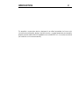
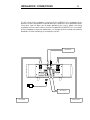
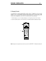
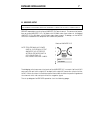
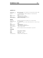
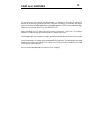
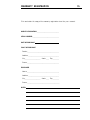
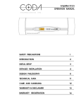
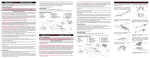
AMPLIFIER 10.5
OPERATION MANUAL
T
E
C
H
N
O
L
O
G
I
E
S
I
N
C
.
SAFETY PRECAUTIONS
1
INTRODUCTION
2
INSTALLATION CONNECTIONS
3
DETAILED INSTALLATION
4
DESIGN PHILOSOPHY
9
TECHNICAL DATA
12
CARE and HANDLING
13
WARRANTY
14
WARRANTY REGISTRATION
15
ADDRESS
16
SAFETY PRECAUTIONS
1
CAUTION
WARNING
!
CAUTION: TO PREVENT ELECTRIC SHOCK,
DO NOT REMOVE COVER. NO USER
SERVICEABLE PARTS INSIDE, REFER
SERVICING TO QUALIFIED SERVICE
PERSONNEL.
THIS SYMBOL IS TO ALERT YOU OF THE
PRESENCE OF UNINSULATED DANGEROUS VOLTAGE WITHIN THE UNIT'S
ENCLOSURE THAT MAY BE OF SUFFICIENT MAGNITUDE TO CONSTITUTE A
RISK OF ELECTRIC SHOCK.
!
THIS SYMBOL IS INTENDED TO ALERT
YOU OF THE PRESENCE OF IMPORTANT
OPERATING AND MAINTENANCE
INSTRUCTIONS IN THE LITERATURE
ACCOMPANYING THE UNIT.
WARNING: TO PREVENT FIRE OR SHOCK HAZARD, DO NOT
EXPOSE THIS UNIT TO RAIN OR MOISTURE. TO
AVOID ELECTRICAL SHOCK, DO NOT OPEN THE
UNIT. REFER SERVICING TO QUALIFIED PERSONNEL.
CAUTION -
Never install or remove the power cord from the chassis
unless it has been disconnected from the AC power source
first.
Never pull on the power cord when removing it from an AC
power source. Grasp it by the plug.
Do not leave the power cord connected to an AC power
source unless it is connected to the unit.
It is recommend that during extended periods of nonuse
that the units power cord be unpluged from its AC power
source.
Route the AC power cord so that it will not be damaged or
walked on.
INTRODUCTION
2
This amplifier is a precision device, designed in an effort to provide the listener with
unmatched sound quality, design, and construction. In order to operate your amplifier
properly and to realize all of the capabilites of the AMPLIFIER 10.5, we recommend that
you read this entire manual carefully.
INSTALLATION CONNECTIONS
3
The first section of the installation instructions for the AMPLIFIER 10.5 is a diagram of the
default ( stereo ) configuration required to bring this amplifier into an operating mode.
These brief steps will allow you to begin operating your system. Make sure during
installation that the main AC power switch on the back of the AMPLIFIER 10.5 is turned off.
While the diagram may be self explanatory, we strongly recommend that you read the
detailed instructions following this introductory section.
PREAMPLIFIER
LEFT CHANNEL
OUTPUT
INPUTS
INPUTS
UNBALANCED
RIGHT CHANNEL
OUTPUT
UNBALANCED
BALANCED
BALANCED
MODE
STEREO
BRIDGED
FOR CONTINUED PROTECTION
AGAINST SHOCK OR FIRE:
1. REPLACE FUSE WITH SAME
T
E
C
H
N
O
L
O
G
I
E
S
I
N
C
.
VOLTAGE REQUIREMENT
HZ
POWER REQUIREMENT
VA
MANUFACTURED IN THE USA
TO RAIN OR MOISTURE
!
AC LINE FUSE CHART
VOLTAGE
WARNING
SERIAL NUMBER
TYPE AND RATING
2. DO NOT EXPOSE THIS UNIT
CAUTION
MODEL
~
AC LINE INPUT
NOTE
MAIN POWER
FUSE AND VOLTAGE SELECTOR
FUSE TYPE
100V
10 AMP
SLOW BLOW 5 x 20mm
120V
10 AMP
SLOW BLOW 5 x 20mm
!
TO PREVENT ELECTRIC SHOCK, DO NOT
REMOVE COVER. NO USER SERVICEABLE
PARTS INSIDE. REFER SERVICING TO
QUALIFIED SERVICE PERSONNEL.
!
DO NOT ALLOW AMPLIFIER OUTPUTS
TO COMMON BETWEEN CHANNELS,
OR CONTACT CHASSIS OR INPUT
220V
5 AMP
SLOW BLOW 5 x 20mm
240V
5 AMP
SLOW BLOW 5 x 20mm
12
0
GROUNDS, OR TO BE CONNECTED
TO ANY ACTIVE CURRENT SOURCE.
SEE SERIAL TAG FOR POWER
REQUIREMENTS, REMOVE POWER
CORD BEFORE CHANGING
FUSE OR LINE VOLTAGE
FUSE VALUE -SEE FUSE CHART
VOLTAGE SELECTIONSEE OPERATION MANUAL
OFF
ON
PREAMPLIFIER
LEFT SPEAKER
RIGHT SPEAKER
DETAILED INSTALLATION
4
I. Source-Output, Power Connections and Controls
The connectors and controls are clearly marked on the back panel of the AMPLIFIER 10.5.
Note the correct left or right channel orientation. The function and channel markings on
the rear panel correspond to the front panel controls and their signal paths.
1.The UNBALANCE and BALANCED inputs should be attached to the appropriate
unbalanced and balanced outputs of a preamplifier either directly or through a
crossover or processor, as appropriate to the application.
2.The LEFT OUTPUT, RIGHT OUTPUT should be attached to the left and right speakers.
NOTE: THERE ARE NO OUTPUT FUSES SO AS TO INSURE A LOW OUTPUT IMPEDANCE.
SPEAKER PROTECTION IS LEFT TO THE SPEAKER MANUFACTER AS THEY WOULD BEST
KNOW HOW TO PROTECT THEIR SPEAKER.
3. The MAIN POWER switch, once all appropriate connectsions are made, may be left on
as the AMPLIFIER 10.5 draws a negligible amount of current when the BIAS is turned off.
4.The FUSE AND VOLTAGE SELECTOR houses a 5 X 20 slow blow fuse and voltage selector
cartridge. Should the fuse blow, contact a Coda dealer or call Coda directly. When
changing the fuse, or altering the voltage selection be sure this unit is disconected from
its AC power source.
5.The AC LINE INPUT should be attached to the power cable provided with the amplifier.
After making the appropriate connections insert the three prong safety plug into an
appropriate AC power source. Once the AMPLIFIER 10.5 is properly connected, the
power switch may be turned on and the led on the front panel will light indicating a ready
state.
1
2
2
LEFT CHANNEL
RIGHT CHANNEL
OUTPUT
INPUTS
INPUTS
UNBALANCED
OUTPUT
UNBALANCED
BALANCED
PUSH
PUSH
BALANCED
FOR CONTINUED PROTECTION
DO NOT ALLOW AMPLIFIER
OUTPUTS TO COMMON
AGAINST SHOCK OR FIRE:
MODEL
1. REPLACE FUSE WITH SAME
SERIAL NUMBER
TYPE AND RATING
VOLTAGE REQUIREMENT
BETWEEN CHANNELS, OR
CONTACT CHASSIS OR
T
E
C
H
N
O
L
O
G
I
E
S
I
N
C
50/60 HZ
VA
.
MANUFACTURED IN THE USA
2. DO NOT EXPOSE THIS UNIT
CURRENT SOURCE.
CAUTION
WARNING
!
AC LINE FUSE CHART
INPUT GROUNDS, OR TO BE
CONNECTED TO ANY ACTIVE
TO RAIN OR MOISTURE
~
AC LINE INPUT
!
TO PREVENT ELECTRIC SHOCK, DO NOT
REMOVE COVER. NO USER SERVICEABLE
PARTS INSIDE. REFER SERVICING TO
QUALIFIED SERVICE PERSONNEL.
FUSE AND VOLTAGE SELECTOR
USE CLASS 1 WIRING
NOTE
MAIN POWER
!
DO NOT ATTACH BOTH
CODA CURRENT AMPLIFIER 20
BALANCED AND UNBALANCED
VOLTAGE
FUSE TYPE
CONNECTORS AT THE SAME TIME
100V
10 AMP
SLOW BLOW 5 x 20mm
120V
10 AMP
SLOW BLOW 5 x 20mm
220V
5 AMP
SLOW BLOW 5 x 20mm
240V
5 AMP
SLOW BLOW 5 x 20mm
120
SEE SERIAL TAG FOR
POWER REQUIREMENTS ,
REMOVE POWER CORD
BEFORE CHANGING FUSE
OR LINE VOLTAGE
5
FUSE VALUE -SEE FUSE CHART
VOLTAGE SELECTIONSEE OPERATION MANUAL
4
OFF
ON
3
DETAILED INSTALLATION
5
II. Front Panel Control Functions and Indicators
1. The BIAS button turns on the bias and opens shunting relays that mute the input.
2. The INPUT SELECTOR button switches between the balanced and unbalanced inputs.
3. These LEDs when lit, indicate that the bias is activated in the AMPLIFIER 10.5.
4. This two color LED indicates that the main power is on. When it is red the balanced
inputs are in use. When it is yellow the unbalanced inputs are in use.
PRECISION BIAS CLASS A/AB AMPLIFIER 10.5
BIAS
INPUT
SELECTOR
1 2
LEFT
RIGHT
3
POWER
RED BAL/YELLOW UNBAL
4
Note: If a power interruption occurs to the system the AMPLIFIER 10.5 defaults to bias off.
DETAILED INSTALLATION
6
III. Remote Control
The AMPLIFIER 10.5 may be operated by remote control. To operate, set the universal
remote to AUX. The provided universal remote can be used to control other Coda
products as well as many other audio and video components. For instructions on the
remotes other capabilities, refer to the Universal Remote Control Manual.
1. The BIAS button turns on the bias and opens shunting relays that mute the input.
2. The BAL«»UNBAL button switches between the balanced and unbalanced inputs.
BIAS
1
PWR
TV
VCR
CTV
AUX
CH+
VOL–
VOL+
CH–
VOL«»BAL
MUTE
DISP
A/B
MONO
MONITOR
PROCESSOR
1
2
3
4
5
6
7
8
9
RCL
0
ENT
BAL«»UNBAL
2
TV/VCR
Note: If a power interruption occurs to the system the AMPLIFIER 10.5 defaults to bias off.
DETAILED INSTALLATION
7
III. BRIDGED SETUP
WARNING: DO NOT OPERATE THIS AMPLIFIER WITH THE TOP COVER REMOVED. NEVER MAKE
ANY INTERNAL ADJUSTMENTS WHILE THIS AMPLIFIER IS CONNECTED TO AN AC POWER SOURCE.
BRIDGED operation consists of one AMPLIFIER 10.5 per channel. The amount of power
from a stereo AMPLIFIER 10.5 is 100 Watts with 25 Watts class A per channel. A bridged
AMPLIFIER 10.5 is 400 Watts with 25 Watts class A per chassis. To bridge, set the MODE
switch on the back of the amplifier to the BRIDGED position.
Back of AMPLIFIER 10.5
NOTE: TURN THE MAIN AC POWER
SWITCH ON THE BACK OF THE
AMPLIFIER 10.5 OFF BEFORE
ALTERING THE MODE SWITCH
OR CONNECTING OR
DISCONNECTING ANY CABLES.
MODE
STEREO
BRIDGED
MODEL
SERIAL NUMBER
The bridging switch commons the inputs of the AMPLIFIER 10.5, were pin 2 of the left XLR
commons with pin 3 of the right XLR, and pin 2 of the right XLR commons with pin 3 of the
left XLR. Whichever input is used the output of that channel will be the positive signal and
the channel which has no input will be the negative signal.
The set up diagram for BRIDGED operation is on the following page.
DETAILED INSTALLATION
8
BRIDGED set up diagram
Before setting up the BRIDGED AMPLIFIER 10.5, read the entire DETAILED INSTALLATION
section of this manual.
_
_
+
LEFT CHANNEL
OUTPUT
INPUTS
INPUTS
UNBALANCED
RIGHT CHANNEL
+
OUTPUT
LEFT CHANNEL
OUTPUT
INPUTS
BALANCED
INPUTS
UNBALANCED
UNBALANCED
BALANCED
BALANCED
MODE
STEREO
STEREO
BRIDGED
FOR CONTINUED PROTECTION
MODEL
CAUTION
SERIAL NUMBER
WARNING
TYPE AND RATING
!
HZ
VOLTAGE REQUIREMENT
T
E
C
H
N
O
L
O
G
I
E
S
I
N
C
AC LINE FUSE CHART
VA
POWER REQUIREMENT
.
MANUFACTURED IN THE USA
TO RAIN OR MOISTURE
VOLTAGE
~
AC LINE INPUT
100V
10 AMP
SLOW BLOW 5 x 20mm
10 AMP
SLOW BLOW 5 x 20mm
!
CAUTION
AGAINST SHOCK OR FIRE:
MODEL
1. REPLACE FUSE WITH SAME
SERIAL NUMBER
TYPE AND RATING
TO PREVENT ELECTRIC SHOCK, DO NOT
REMOVE COVER. NO USER SERVICEABLE
PARTS INSIDE. REFER SERVICING TO
QUALIFIED SERVICE PERSONNEL.
NOTE
MAIN POWER
FUSE AND VOLTAGE SELECTOR
FUSE TYPE
120V
!
AC LINE FUSE CHART
VOLTAGE
TO COMMON BETWEEN CHANNELS,
WARNING
HZ
VOLTAGE REQUIREMENT
2. DO NOT EXPOSE THIS UNIT
T
E
C
H
N
O
L
O
G
I
E
S
I
N
C
VA
POWER REQUIREMENT
.
MANUFACTURED IN THE USA
TO RAIN OR MOISTURE
!
DO NOT ALLOW AMPLIFIER OUTPUTS
~
AC LINE INPUT
220V
5 AMP
SLOW BLOW 5 x 20mm
5 AMP
SLOW BLOW 5 x 20mm
12
0
100V
10 AMP
SLOW BLOW 5 x 20mm
120V
10 AMP
SLOW BLOW 5 x 20mm
FUSE VALUE -SEE FUSE CHART
VOLTAGE SELECTIONSEE OPERATION MANUAL
OFF
!
DO NOT ALLOW AMPLIFIER OUTPUTS
TO COMMON BETWEEN CHANNELS,
OR CONTACT CHASSIS OR INPUT
12
0
GROUNDS, OR TO BE CONNECTED
TO ANY ACTIVE CURRENT SOURCE.
SEE SERIAL TAG FOR POWER
REQUIREMENTS, REMOVE POWER
CORD BEFORE CHANGING
FUSE OR LINE VOLTAGE
!
TO PREVENT ELECTRIC SHOCK, DO NOT
REMOVE COVER. NO USER SERVICEABLE
PARTS INSIDE. REFER SERVICING TO
QUALIFIED SERVICE PERSONNEL.
NOTE
MAIN POWER
FUSE AND VOLTAGE SELECTOR
FUSE TYPE
OR CONTACT CHASSIS OR INPUT
240V
OUTPUT
BALANCED
MODE
BRIDGED
FOR CONTINUED PROTECTION
AGAINST SHOCK OR FIRE:
1. REPLACE FUSE WITH SAME
2. DO NOT EXPOSE THIS UNIT
RIGHT CHANNEL
UNBALANCED
ON
220V
5 AMP
SLOW BLOW 5 x 20mm
240V
5 AMP
SLOW BLOW 5 x 20mm
TO ANY ACTIVE CURRENT SOURCE.
SEE SERIAL TAG FOR POWER
REQUIREMENTS, REMOVE POWER
CORD BEFORE CHANGING
FUSE OR LINE VOLTAGE
RIGHT SPEAKER
PREAMPLIFIER
GROUNDS, OR TO BE CONNECTED
FUSE VALUE -SEE FUSE CHART
VOLTAGE SELECTIONSEE OPERATION MANUAL
OFF
ON
LEFT SPEAKER
DESIGN PHILOSOPHY
9
I. Design Philosophy and Approach
The subtlety of the design process at this level of performance makes it impossible to
easily explain all of the advantages inherent in the Amplifier 11.5. However, we present
here an overview to give you an understanding of some of its unique features and an
idea of the listening experience you can expect. Often a particular technique has
numerous unrelated advantages and possibilities. We make every effort to exploit these
advantages with the final result being an amplifier that is greater than the sum of its
individual features
The topology and component selection is built on the foundation established by the
Amplifier System 100. Balanced interconnections are provided to take advantage of
their greater noise rejection as in the 100. Differential voltage gain throughout provides
exceptional rejection of external noise and contributes to the inherent DC stability of the
circuit. This allows direct coupling without servo circuitry. The unit also uses output
followers operating without feedback.
The front end of the Amplifier 11.5 is designed to operate without ever entering Class B
operation as is common in many other designs. This combined with excellent high
frequency design insures linear operation at high speed, and translates into a sonic
reproduction which is extremely transparent in character. The supplie take a very direct
approach to high performance. First, a top quality toroid transformer and over 200,000
uf of capacitance with very low ESR and inductance is used. For optimum performance
and reliability all circuity remains continuosly powered.
The specifications are consistent with what would be expected in a high current Class A
amplifier design. In this design , however , an unusual degree of attention has been paid
to sonically meaningful parameters.
For example, the current stage is capable of producing peak currents in excess of 100
Amperes with a degree of linearity and speed which is not matched by other designs
when producing only a fraction of of this current. This is achieved by the implementation
of several distinct circuit features.
In the Amplifier 11.5 extremely wide bandwidth output transistors are used instead of the
usual TO3 devices which are used in other transistor designs. Each channel uses 24
individual output transistors with a combined power rating of 4800 Watts and 180
Amperes with a bandwidth of 10 Mhz.
The manner in which the Amplifier 11.5 accomplishes Class A operation is also different
than that employed in conventional designs. All Class A designs leave Class A operation
when they are operated into loads of sufficiently low impedance or power levels.
Generally, this transition will produce a large and abrupt distortion increase.
The Amplifier 11.5 uses bias voltages and component values which have been specifically selected to produce a precision transition with no abrupt changes in distortion or
output impedance. This “Precision Bias” technique yields seemless performance regardless of the complexity of the load impedance and is particularly effective at eliminating
a form of IM distortion which often occurs in these instances.
DESIGN PHILOSOPHY
10
To maintain “Precision Bias” requires an advanced bias circuit that must have a very high
degree of stability under a wide range of temperatures and load conditions. The usual
bias network is of such high impedance and poor thermal regulation that at the extremes
of operation, bias currents are ineffectively controlled. Advanced tracking techniques
results in absolute control of bias curents under all conditions in the Amplifier 11.5.
The main power supply of the amplifier consists of a 2000VA toroidal power transformer
with independent rectifiers to isolate the channels from one another. One hundred
thousand microfarads of total capacitance provide effective filtering.
The above attributes result in a amplifier of such extreme linearity and bandwidth that no
overall feedback correction is required or used. One advantage of this is a high degree
of immunity from interactions with loads or cables and a superior transient response. An
extremely low nonreactive output impedance is maintained well beyond 20,000 hz. The
resulting uniform damping factor is not usually found in other designs.
The Amplifier 11.5 has all structural parts made of machined aluminum which are milled
to very close tolerances yielding the seemless appearance characteristic of previous
products from Coda. As with all Class A amplifiers, heat dissipation is important. The
Amplifier 11.5 uses six massive heat sinks for efficient, noiseless, and clean thermal relief.
The thermal coefficient of the heat sinks is one of the lowest and most effective in the
audio industry.
DESIGN PHILOSOPHY
11
II. Parts' Quality
1. Finishes - All exterior metal parts are anodized or powder coated. Anodizing for its
multiple finishing and powder coating for durability.
2. Circuit Boards - Circuit boards are fiberglass epoxy with gold plating over a tin/nickel
barrier. This gold layer will not corrode, while the barrier plate prevents the gold from
migrating to the lower copper layer and detracting from its appearance.
3. Resistors - All are high reliability metal film 1% resistors for 1/4 watt and 5% for 1 watt.
4. Capacitors - All capacitors have been eliminated where possible on the premise that
“no cap is better than the best cap.” The only electrolytics used are in the power supply
where large numbers provide enormous filtering capacitance for the supply.
5. Semiconductors - There are no integrated circuits (IC) in the signal path. Very high
quality dual FETs were selected for their superb noise performance and precision
matching. The remaining semiconductors are also of very high quality, each possessing
parameters ideally suited for the specific application.
6. Connectors - Coda employs a standard RCA configuration with a gold plated case.
The XLR input and output connectors are manufactured by Neutrik of Switzerland.
Speaker connecters are also gold plated.
7. Wire - All signal wire has been eliminated whenever possible. Where wire is used,
Coda employs solid silver and silver plated copper, 141 strand, 18 guage wire with a
silicone insulation.
TECHNICAL DATA
12
AMPLIFIER 10.5
Rated Power:
Frequency Response:
Distortion:
Gain:
Maximum Current:
Noise:
input Impedance:
Output Impedance:
100 Watts with 25 Watts class A @ 8 Ohms both channels driven from 20Hz to 20kHz
DC to -3dB @ 100kHz
< .1 percent from 10Hz to 20kHz @ 100 Watts both channels driven into
2 Ohm through 8 Ohms
26dB
>80 Amperes peak per channel
-100dB referenced to rated output
50k Ohms unbalanced/1k Ohms balanced
.05 Ohms from 20Hz to 20kHz
BRIDGED
Rated Power:
Frequency Response:
Distortion:
Gain:
Maximum Current:
Noise:
Input Impedance:
Output Impedance:
400 Watts with 25 Watts class A @ 8 Ohms mono from 20Hz to 20kHz
DC to -3dB @ 100kHz
< .1 percent from 10 Hz to 20kHz @ 400 Watts driven into 2 Ohms through
8 Ohms
32dB
>80 Amperes peak
-100dB referenced to rated output
1k Ohms unbalanced/1k Ohms balanced
.1 Ohms from 20Hz to 20kHz
SUPPLY
1000 VA toroidal power transformer and 120,000 uF of capacitance
DIMENSIONS
Height:
Width:
Depth:
Weight:
Power requirement:
5.25" Faceplate, 6.0" Overall
19.0" Faceplate, 17.0" Chassis
12.5" Overall
45 lbs., 50 lbs., Shipping
450 Watts maximum at rated power
CARE and HANDLING
13
The interior of the unit requires no special care. If it becomes necessary to clean the
exterior, a simple dusting may be all that is required. If a cleaner is necessary, any dilute
commercial ammonia based product will be appropriate. NEVER use any abrasive rags,
cleaners or chemical solvents on the AMPLIFIER 10.5.
When handling the unit, take care not to mar the aluminum. Aluminum is a medium
hardness metal and can be scratched by the harder tool steels.
Avoid exposing the unit to direct sunlight, and keep it away from sources of intense heat.
Do not throw away the carton or associated packing material. They are ideal if you need
to pack the unit for moving and in the unlikely event that servicing is needed, they will be
necessary for safe shipment.
Be sure to provide adequate insurance when shipping.
WARRANTY
14
I. Warranty- Any failure of the Amplifier 10.5 to operate or to meet specifications,
applicable at time of manufacture, due to a manufacturing defect or component
failure, will be corrected by Coda Technologies, Inc. without charge for parts, or labor
for a period of ten years from date of original purchase. Coda Technologies, Inc. will
provide for surface transportation to and from the factory from an authorized Coda
Technologies, Inc. dealer for a period of one year from date of purchase.
II. Procedure- If the Amplifier 10.5 should require service under warranty, take it with proof
of purchase date, with its carton and packing material, to a Coda Technologies, Inc.
dealer. The dealer will arrange for service. Direct shipments to the factory will be
accepted at the discretion of the company. Coda Technologies, Inc. products
purchased outside of the U.S. will be covered by those warranty conditions extended by
the importing distributor which may differ in some respects from those given above.
Warranty service, if required, is the responsibility of the importing distributor. If a Coda
Technologies, Inc. product is removed from the country of original purchase, Coda
Technologies, Inc. distributors or dealers are not obligated by the conditions of this
warranty and repairs will be affected at their discretion.
III. Exclusion of Coverage- At the sole opinion of Coda Technologies, Inc. the following
situations are specifically excluded from coverage:
1. Any Amplifier 10.5 not operated in accordance with the instructions contained in this
manual, or otherwise subjected to abuse, tampering, modification, accidental damage,
or serial number defacement.
2. Damage to other property caused by any defects in this product, damages based
upon inconvenience, loss of use of the product, loss of time, commercial loss, or any other
damage whether incidental, consequential, or otherwise.
3. It is Coda Technologies, Inc. policy to extend coverage when reasonable doubt exist;
however, freight charges will be billed for any units returned under warranty and found
by the company to be operating according to specification.
This warranty gives you specific legal rights, and you may also have other rights which
vary from state to state.
Coda Technologies, Inc. continually researches new techniques, designs, and construction
methods and so reserves the right to introduce refinements into current product lines
without notice or obligation. The company may offer product modifications to make
these refinements available to earlier production units.
WARRANTY REGISTRATION
Fill in and retain this copy of the warranty registration sheet for your records .
MODEL DESIGNATION:__________________________________
SERIAL NUMBER:______________________________________
DATE OF PURCHASE:
PLACE OF PURCHASE
Dealer:___________________________________________
Address:__________________________________________
City:_____________________ State:____ Zip:__________
Phone:____________________________________________
PURCHASER
Name:_____________________________________________
Address:__________________________________________
City:_____________________ State:____ Zip:__________
Phone:____________________________________________
NOTES:
15
WARRANTY REGISTRATION
15.5
Please fill in and send this copy of the warranty registration sheet to Coda Technologies,
Inc. Include copy of proof of purchase.
MODEL DESIGNATION:__________________________________
SERIAL NUMBER:______________________________________
DATE OF PURCHASE:
PLACE OF PURCHASE
Dealer:___________________________________________
Address:__________________________________________
City:_____________________ State:____ Zip:__________
Phone:____________________________________________
PURCHASER
Name:_____________________________________________
Address:__________________________________________
City:_____________________ State:____ Zip:__________
Phone:____________________________________________
NOTES:
ADDRESS
Coda Technologies, Inc.
9941 Horn Road Suite A
Sacramento, CA 95827
Phone: (916) 363-4653
Fax:
(916) 363-4627
16