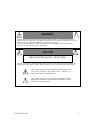
1
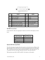
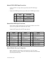
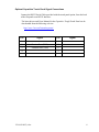
PROFORMANCE Rugged COTS 4418 Flat Panel Display User’s Guide for Rack and Panel Mount W/DVC CONTROLLER (4418R3C/R4C/P4C) Document No. 150-4418-002 Rev. (–), APRIL 2005 NOTICE This manual is subject to change without notice and should not be construed to be a commitment in any form by Aydin Displays. Aydin Displays reserves the right to make improvements to the product at any time. It is understood that the delivered product will be of the latest possible design and that it may not be exactly as stated herein. This manual may contain descriptions of functions not implemented at time of distribution, unless prior contractual arrangements have been made. Aydin Displays reserves the right to modify or revise the content of this manual. It is further understood that in consideration of the receipt or purchase of this manual, the recipient or purchaser agrees not to reproduce, disseminate the information herein, or copy it by any means whatsoever, nor to permit such actions by others, for any purpose, without the written permission of Aydin Displays. All trademarks and registered trademarks are recognized as the property of their respective owners. Doc. No. 150-4418-002 Rev. (–), APRIL 2005 150-4418-002(-).doc ii FEDERAL COMMUNICATIONS COMMISSION REQUIREMENTS This device complies with part 15 of the FCC Rules. Operation is subject to the following two conditions: (1) This device may not cause harmful interference, and (2) this device must accept any interference received, including interference that may cause undesired operation. Use the specified cables with the 4418 display so as not to interfere with radio and television reception: Use the shielded video cable. Series 4418 products have been tested and found to comply with the limits for Class A, pursuant to part 15 of FCC rules. These limits are designed to provide reasonable protection against harmful interference in a residential installation. This equipment generates, uses and can radiate radio frequency energy and, if not installed and used in strict accordance with the instructions, may cause harmful interference to radio communications. However, there is no guarantee that interference will not occur in a particular installation. If this equipment does cause harmful interference to radio or television reception, which can be determined by turning the equipment off and on, the user is encouraged to try to correct the interference by one or more of the following measures: Reorient or relocate the receiving antenna. Increase the separation between the equipment and the receiver. Connect the equipment into an outlet on a circuit different from that to which the receiver is connected. Consult the dealer or an experienced radio/TV technician for help. 150-4418-002(-).doc iii WARNING ! TO PREVENT FIRE OR SHOCK HAZARDS, DO NOT EXPOSE THIS UNIT TO RAIN OR MOISTURE. ALSO DO NOT USE THIS UNIT’S POLARIZED PLUG WITH AN EXTENSION CORD RECEPTACLE OR OTHER OUTLETS UNLESS THE PRONGS CAN BE FULLY INSERTED. DO NOT OPEN THE CABINET. THERE ARE HIGH VOLTAGE COMPONENTS INSIDE. REFER SERVICING TO QUALIFIED SERVICE PERSONNEL. CAUTION ! RISK OF ELECTRIC SHOCK. DO NOT OPEN. CAUTION: TO REDUCE THE RISK OF ELECTRIC SHOCK, DO NOT REMOVE COVER OR BACK, NO USER-SERVICEABLE PARTS INSIDE. REFER SERVICING TO QUALIFIED SERVICE PERSONNEL. This symbol warns the user that uninsulated voltage within the unit may be large enough to cause electric shock. Therefore, it is dangerous to touch any part inside the unit. ! 150-4418-002(-).doc This symbol alerts the user that important literature about the operation and maintenance of this unit has been included. Read it carefully to avoid any problems. iv PRODUCT SAFETY PRECAUTIONS The socket-outlet of external power supply shall be installed near the equipment and shall be easily accessible. Follow all warnings and instructions marked on the display. Do not attempt to service this display yourself. Removing the display cover or back may expose you to dangerous voltage or other risks. Refer all servicing to qualified service personnel. Adequate ventilation must be maintained to ensure reliable and continued operation and to protect the display from overheating. Do not block ventilation slots and openings or install the display in a place where ventilation may be hindered. To protect from electrical shock, unplug the displays power supply from the wall outlet before relocating. Do not expose this display to direct sunlight or heat. Hot air may cause damage to the cabinet and other parts. This display should be operated from the type of power source indicated on the displays rating label. Do not allow metal pieces or objects of any kind to fall into the display through the ventilation holes. Do not use this display near water. Do not place any heavy objects on the power cord. Damage to the cord may cause shock or fire. Unplug this displays power supply from the wall outlet and refer servicing to qualified service personnel in the event that: Power cord or plug is damaged or frayed. Liquid is spilled into the display or the display is exposed to rain or water. The display does not operate normally when the operating instructions are followed. The display has been dropped or the cabinet damaged. The display exhibits a distinct change in performance, indicating a need for service. 150-4418-002(-).doc v Thank you for purchasing this Aydin Displays PROFORMANCE display. ♦ 4418 LCD Display ♦ Power cord (except for DC Input versions) ♦ HD15 VGA Video Cable or DVI Video Cable depending on selected video option ♦ Mounting Hardware (if applicable) ♦ Product CD containing: – – – This User’s Guide Warranty Guide Touch Accessories (if applicable) ♦ Various accessories based on configuration Please check the carton and its contents for damage that may have occurred during shipment. Report any damage to the shipping agent immediately and do not operate the display if it appears to have been damaged. All warranty returns must use the original shipping carton and packaging materials to prevent damage. 150-4418-002(-).doc vi Table of Contents 1.0 CONNECTIONS AND SETUP ........................................................................ 3 Power Connections .............................................................................................................. 3 AC Power (standard) ....................................................................................................... 3 DC Power (optional) ........................................................................................................ 3 Signal Connections .............................................................................................................. 3 VGA Video Signal Connections ...................................................................................... 3 VGA BNC Connections .................................................................................................. 4 Optional A/B Video Input Select ..................................................................................... 4 Optional NTSC/S VIDEO Signal Connections ............................................................... 5 Optional DVI-D VIDEO Signal Connections ................................................................. 5 Optional Multiple Video Input Configuration ................................................................. 5 Optional Capacitive Touch Panel Signal Connections .................................................... 6 2.0 DISPLAY ADJUSTMENT ............................................................................... 7 6.3 Control Panel Function Buttons............................................................................... 7 LCD Adjustment Pushbuttons ......................................................................................... 7 Power Management ......................................................................................................... 8 On-Screen Control Function Items ...................................................................................... 9 OSD Operating Instructions and Menus ............................................................................ 10 Control Function Items ...................................................................................................... 12 Optional Full Dimming.................................................................................................. 12 Optional Active Contrast Enhancement ........................................................................ 12 Optional A/B Video Input Select ................................................................................... 12 Optional Brightness and Contrast Operation ..................................................................... 12 System Daytime Color Setting ...................................................................................... 12 System Dusk Color Setting............................................................................................ 12 System Night-Time Color Setting ................................................................................. 12 3.0 Optional Equipment .................................................................................... 13 4.0 4418 SPECIFICATIONS ............................................................................... 14 LCD Module ...................................................................................................................... 14 Input Signal ........................................................................................................................ 14 Synchronization Range ...................................................................................................... 14 Dimming Range ................................................................................................................. 14 Brightness .......................................................................................................................... 14 Resolutions Supported ....................................................................................................... 15 Power Consumption........................................................................................................... 15 Dimensions ........................................................................................................................ 16 Weights .............................................................................................................................. 16 Operating Environment ..................................................................................................... 16 5.0 TROUBLESHOOTING TIPS ......................................................................... 17 6.0 Rugged COTS 4418 DISPLAY DIMENSIONS ............................................. 18 6.1 4418R3C/R4C Rack Mount Dimensions............................................................... 19 6.2 4418P4C Panel Mount Dimensions ....................................................................... 21 150-4418-002(-).doc 1 4418 DISPLAY FEATURES • Capable of displaying 16,777,216 colors: Colors displayed in a continuous spectrum, providing a truer representation of color. The display’s highcontrast LCD enhances color vibrancy and improves focus with no geometric distortion. • Multiple Frequency Technology: Automatically adjusts the display to the video card’s scanning frequency, thus displaying the resolution required within the preset formats. • Industrial Packages: Available in Rack Mount and Panel Mount configurations. • Touch Systems: Optional Capacitive Tough Touch Panel with RS232 interface. • Anti-Reflective Screen: All industrial non-touch models are supplied with Anti-reflective protective safety glass. • Power Supply: All units are supplied with an internal power supply. 150-4418-002(-).doc 2 1.0 CONNECTIONS AND SETUP To connect the LCD display to your system, follow these instructions: CAUTION: Turn power off to both the computer and display before making any connections and unplug power supply. The power ON/OFF switch designations are as follows: ON OFF Power Connections AC Power (standard) AC operating input voltage is 115/230 VAC Auto-ranging, 47-440 Hz. Connect the AC line power cord to a grounded outlet. For maximum protection, use a good surge protector between the outlet and the power supply to avoid damage to the display due to electrical service abnormalities. DC Power (optional) Connect DC Power, 24VDC (-3Vdc, +8Vdc), to the DC Input Connector using a MIL connector P/N MS3476W8-33S (not supplied). Pin assignments are as follows: Pin A B C Signal +VDC +VDC Return Safety Ground Signal Connections VGA Video Signal Connections The LCD is supplied with a 15-pin, D-sub to 15-pin, D-sub cable. Pin assignments for the 15-pin connector are shown below. 150-4418-002(-).doc 3 Pin Signal Pin Signal 1 Red Video Signal 9 No Connection 2 Green Video Signal 10 Ground 3 Blue Video Signal 11 Ground 4 Ground 12 No Connection 5 No Connection 13 Horizontal Sync Signal 6 Ground for Red Video Signal 14 Vertical Sync Signal 7 Ground for Green Video Signal 15 No Connection 8 Ground for Blue Video Signal VGA BNC Connections Connect the BNC cables to the appropriate connectors on the back of the display as shown below: Cable Connector Red Green/Sync Blue H/Composite Sync Vertical Sync Display Rear Panel Connector R G/Sync B H/CS V Optional A/B Video Input Select The A/B video input select option allows the operator to select between two different video inputs through use of an A/B video select switch mounted on the bottom of the front panel. The ‘A’ position selects the video input connected to the HD15 video input connector. The ‘B’ position selects the video input connected to the BNC video input connectors. When option not provided, the HD15 and BNC video inputs are tied together. 150-4418-002(-).doc 4 Optional NTSC/S VIDEO Signal Connections – Connect the NTSC coax input cable (not provided) to the NTSC BNC input connector. – Connect the S VIDEO input cable (not provided) to the S VIDEO input connector. Pin Name Description 1 GND Ground (Y) 2 GND Ground (C) 3 Y Intensity (Luminance) 4 C Color (Chrominance) Optional DVI-D VIDEO Signal Connections The DVI input is Digital Video input only. The DVI input connector uses a DVI-I connector to accept both DVI-I and DVI-D video cables. Connect the DVI input cable to the DVI input connector. Pin Signal Pin Signal Pin Signal 1 T.M.D.S. DATA 2- 9 T.M.D.S. DATA 1- 17 T.M.D.S. DATA 0- 2 10 12 T.M.D.S. DATA 1+ T.M.D.S. DATA 1/3 SHIELD T.M.D.S. DATA 3- 18 4 T.M.D.S. DATA 2+ T.M.D.S. DATA 2/4 SHIELD T.M.D.S. DATA 4- 20 T.M.D.S. DATA 0+ T.M.D.S. DATA 0/5 SHIELD T.M.D.S. DATA 5- 5 T.M.D.S. DATA 4+ 13 T.M.D.S. DATA 3+ 21 T.M.D.S. DATA 5+ 6 DDC CLOCK 14 +5 POWER 22 T.M.D.S. CLOCK SHIELD 7 DDC DATA 15 GND 23 T.M.D.S. CLOCK+ 8 NO CONNECT 16 HOT PLUG DETECT 24 T.M.D.S. CLOCK- 3 11 19 Optional Multiple Video Input Configuration When a combination of more than one Video input type (VGA, DVI, and/or NTSC/S-Video) is provided, a Video select switch is provided on the Front Panel to select the desired Video source. 150-4418-002(-).doc 5 Optional Capacitive Touch Panel Signal Connections Connect the RS232 Serial Cable provided with the touch panel option, from the back of the flat panel to an RS232 Interface. The latest drivers and Users Manual for the Capacitive Tough Touch Panel can be downloaded from the following web site: http://www.3m.com/3mtouchsystems/ Pin Signal 1 Pin 6 2 Receive Data (RXD) 7 3 Transmit Data (TXD) 8 4 5 150-4418-002(-).doc Signal 9 GND 6 2.0 DISPLAY ADJUSTMENT If you have any problems connecting, setting up or operating the display, please refer to the Troubleshooting section of this guide. Plug the LCD power cord into an AC power source. The green ON LED should light. When the display has power applied, and either the computer or video card is in power save mode, the amber SAVE LED will be on. A typical adjustment sequence is: Width, Horizontal Position, repeat Width, Focus and then Vertical Position. Display height is preset and not adjustable. 6.3 Control Panel Function Buttons LCD Adjustment Pushbuttons When necessary, the unit is adjusted using an On-Screen Display (OSD) and the following pushbuttons: OSD and SELECT MODE Enables the Main Menu, Sub Menu, and parameter to be adjusted. ADJUST & SELECT The pushbuttons are used to select a main or sub menu and are then used to make the adjustments once a function is selected using the OSD and SELECT MODE key. EXIT The EXIT pushbutton is the complement of SELECT MODE and allows you to exit menu selections by returning the user to the previous menu or exiting the OSD. The EXIT pushbutton is also a Hot Button for the Auto Adjust Function when the OSD is not enabled. 150-4418-002(-).doc 7 Power Management When Horizontal or Vertical Sync is not detected, the green POWER status indicator will extinguish and the amber SAVE indicator will light and the No Sync symbol will appear (see below). When the Horizontal or Vertical Synchronization frequencies being supplied to the unit are not within the range of the AMLCD monitor, or when No Signal is applied, the No Sync symbol will appear. No Sync! 150-4418-002(-).doc 8 On-Screen Control Function Items DISPLAY IMAGE Scaling Brightness Contrast Hue Saturation Black Level Sets Display Aspect Ratio Luminance of backlight control White-level of video signal control Color Balance Color Intensity Black-level of video signal Auto Adjust Automatically adjusts Phase, Clock, Horz., and Vert. to produce the optimal picture. (Note: May require some minor adjustments on nonstandard formats) Auto gain control for the amplitude on the video input signal Adjust the phase of the sampling clock to produce a sharp image. Adjust the width of the display by changing the sampling rate of the incoming video. Used to center the image left to right Used to center the image up & down Auto Gain Phase Clock Horizontal Vertical sRGB Color Temp RED GREEN BLUE Used to display TV type color image with RGB Signal Sets Color Temp. to either of 2 standards or can be User adjusted using the R,G,B controls below. Adjust Red color video level highlights Adjust Green color video level highlights Adjust Blue color video level highlights LANGUAGE English Chinese Korean Japanese French Spanish Set OSD language to ENGLISH Not Available Not Available Not Available Not Available Not Available OSD/RESET Factory Reset Horizontal Vertical Blend Timeout Reset to factory-default value Horizontal position adjust Vertical position adjust Adjust background of OSD from opaque to transparent Set the auto timeout for OSD COLOR Each selected value is stored in LCD memory after EXIT button is depressed or time out occurs. The stored values are not affected even if the power is turned off. However, the selected value is not stored if power is turned off before time out or pressing the EXIT button. 150-4418-002(-).doc 9 OSD Operating Instructions and Menus 1. Apply power to the LCD Display. 2. Depressing the button once will bring up the On- Screen Display. The first menu that comes up is the DISPLAY MENU as show below. As you press either the or key the selected MENU (as indicated by a blue background) on the top of the main menu will change. The five main menus are shown below. DISPLAY IMAGE COLOR LANGUAGE OSD/RESET 150-4418-002(-).doc 10 3. Once you have selected the main menu that you want to use, you must then press the Select Key to activate that menu. When the menu has been activated, the first selection on the menu will become highlighted as indicated by a BLUE DOT to the left of the selection and a raised background. Only those selections with WHITE letters are available for selection. By using the [ + ] or [ - ] keys, each selection on the menu will become highlighted. To activate the selected function, press the Mode Select Key, this will then highlight the adjustment indicator bar. By pressing the [ + ] or [ - ] keys the value of the function can be adjusted. 4. To save this setting, use the Exit Key to move up one level in the menu. Note, each time you press the exit key you will move up one level until you exit the OSD all together. 5. Each selected value is stored in the LCD’s memory after the Exit button is depressed or time out occurs. The stored values are not affected even if the power is turned off. However, the selected value is not stored if power is turned off before time out or pressing the Exit button has occurred.. 6. When FACTORY RESET is selected under the OSD/RESET MENU a warning will appear as shown below. Select YES or NO by pressing the [ + ] or [ - ] key and then press the Mode Select Key to enter your choice. Notes: 1. There is an automatic timeout (set by the operator) for the OSD. If no pushbuttons are depressed for five to sixty seconds, the OSD will turn off and any adjustments made to that point will be stored. If the Timeout is set to zero, the OSD will stay enabled until disabled by the EXIT button or power is turned off. 2. The Auto Gain and Auto Adjust functions take approximately 4 seconds to be performed. 150-4418-002(-).doc 11 Control Function Items Optional Full Dimming This option allows the operator to adjust the brightness of the display from full Brightness to full OFF depending on the time of day or ambient lighting conditions. The Brightness potentiometer is located at the bottom of the front panel. Optional Active Contrast Enhancement This option allows the operator to adjust the contrast of the display to an optimal level depending on the time of day or ambient lighting conditions. The Contrast potentiometer is located at the bottom of the front panel. Optional A/B Video Input Select The A/B video input select option allows the operator to select between two different video inputs through use of an A/B video select switch mounted on the bottom of the front panel. The ‘A’ position selects the video input connected to the HD15 video input connector. The ‘B’ position selects the video input connected to the BNC video input connectors. When option not provided, the HD15 and BNC video inputs are tied together. Optional Brightness and Contrast Operation The Brightness and Contrast potentiometers when present are located at the bottom of the front panel. System Daytime Color Setting Contrast: Brightness: Minimum Maximum System Dusk Color Setting Contrast: Brightness: Increase contrast until picture distorts and turn back slightly until distortion disappears. Decrease brightness to suit desired level for system dusk color setting. System Night-Time Color Setting Contrast: Brightness: Increase contrast until picture distorts and turn back slightly until distortion disappears. Decrease brightness to suit desired level for system night time color setting. 150-4418-002(-).doc 12 3.0 ♦ ♦ ♦ ♦ ♦ ♦ ♦ ♦ ♦ Optional Equipment NTSC/S VIDEO input DVI Video input A/B Video Input Select Full Dimming Brightness enhancement Contrast enhancements Remote dimming control (4418R3C) Sunlight readable (4418R4C)/ (4418P4C) Touch Screens: Capacitive 150-4418-002(-).doc 13 4.0 4418 SPECIFICATIONS NOTE Technical specifications are subject to change without notice. LCD Module ♦ ♦ ♦ ♦ ♦ ♦ ♦ ♦ ♦ Active matrix; thin film transistor (TFT) liquid crystal display (LCD) Luminance: 200cd/m2 (typical) Contrast ratio: 300:1 (typical) Display colors: 16,777,216 Diagonal: 18.1 inches Viewable Image Size: 359.04 (H) x 287.232 (V) mm Native Resolution (Pixel Count): 1280 x 1024 Pixel pitch: 0.2805 (H) x 0.2805 (V) mm Viewing Angle: 85° (typical) Left, Right, Up, Down with more than 10:1 contrast ratio Input Signal ♦ Video: Analog 0.7 Vp-p/75 Ohms ♦ Sync: Separate Sync TTL Level; Horizontal Sync Position/Negative; Vertical Sync Positive/Negative; Composite Sync Positive/Negative, TTL Level; Sync on Green Video (Positive) 0.7 Vp-p and sync Negative 0.3 Vp-p Synchronization Range Both Horizontal and Vertical sync are performed automatically. ♦ Horizontal: 24.8 kHz to 91 kHz ♦ Vertical: 47.2 Hz to 89 Hz Dimming Range ♦ Front Panel control dim to zero ♦ 450:1 usable dimming range Brightness ♦ 200 cd/m2 (typical) ♦ 180 cd/m2 (typ. W/EMI faceplate) ♦ 158 cd/m2 (typ. W/EMI faceplate and AR Capacitive Tough Touch Panel) 150-4418-002(-).doc 14 Resolutions Supported NOTE Resolution is based on horizontal and vertical frequencies only. Some systems may not support all modes listed. ♦ ♦ ♦ ♦ ♦ ♦ ♦ ♦ 720 x 400* VGA text at 70 Hz to 85 Hz 640 x 480 at 60 Hz to 85 Hz 800 x 600* at 60 Hz to 85 Hz 1152 x 750* at 80 Hz 1152 x 864* at 70 Hz to 85 Hz 1152 x 900* at 66 Hz to 76 Hz 1024 x 768* at 60 Hz to 85Hz 1280 x 1024 at 47 Hz to 76 Hz; for optimal display performance at this resolution, operation at 60 Hz is recommended. * Interpolated Resolutions: when resolutions are displayed that are lower than the pixel count (native resolution) of the LCD module, text may appear choppy or lines may appear to be bold. This is normal and necessary for all current flat panel technologies when displaying none-native resolutions full screen. In flat panel technologies, each dot on the screen is one pixel, so to expand resolutions to fill the screen, an interpolation of the resolution must be done. When the interpolated resolution is not an exact multiple of the native resolution, some lines may appear thicker than others. Power Consumption Input 120 V AC: 120 V AC 60Hz @ 0.84 Amps 68 Watts typical 150-4418-002(-).doc 15 Dimensions See the dimension drawings at the back of this Users Guide. Weights ♦ Rack Mount: 21.0 lbs. (R3C), 21.5 lbs. (R4C) ♦ Panel Mount: 22.5 lbs. (P4C) ♦ With Capacitive Tough Touch – Rack Mount: 31.5 lbs. (R4C) – Panel Mount: 32.5 lbs. (P4C) Operating Environment ♦ Shock: MIL-S-901D, Grade A, Class I, Type A (4418R4C)/(4418P4C) MIL-S-901D, Grade B, Class I, Type A (4418R3C) ♦ Vibration: MIL-STD-167-1, Type 1 (4418R4C)/ (4418P4C) IEC-60945 3rd Edition, 1996 (4418R3C) ♦ EMI: MIL-STD-461D (4418R4C)/ (4418P4C) CE101 pass with exception CE102 pass RE101 pass with exception RE102 pass FCC class A (4418R3C) IEC-60945 3rd Edition, 1996 (4418R3C) ♦ Drip Proof: MIL-STD-810E, Method 506.3 Procedure II; Front Panel Only (4418R4C)/ (4418P4C) ♦ Sand/Dust: MIL-STD-810E, Method 510.3 Front Panel Only (4418R4C)/ (4418P4C) ♦ Temperature: 32°F to 122°F (0°C to +50°C) ♦ Humidity: 5% to 95% R.H. non-condensing ♦ Altitude: 0 to 42,000 feet ASL ♦ Storage Temperature: -30°C to +71°C (-40° storage is available as an option) ♦ Storage Humidity: 5% to 95% R.H. ♦ Storage Altitude: 0 to 54,000 feet ASL 150-4418-002(-).doc 16 5.0 TROUBLESHOOTING TIPS If you experience trouble with your 4418 display, check the following items before contacting Aydin Displays or your dealer. Trouble Troubleshooting Tip No picture • The signal cable should be completely connected to the display card/computer. • The display card should be completely seated in the slot. • Display power connector should be plugged in and computer power switch should be in the ON position. Make sure that a supported mode has been selected on the display card. Please check your display card or system manual to change graphics mode. • Check the monitor and your display card for compatibility and recommended settings. • Check the signal cable connector for bent or pushed-in pins. Image persistence. • Image persistence occurs when a ghost of an image remains on the screen even after the monitor has been turned off. Unlike a CRT monitor, a LCD monitors image persistence is not permanent. To erase an image ghost, turn the monitor off for as long as the image was displayed. If an image was on the monitor for an hour and a ghost of that image remains, the monitor should be turned off for an hour to erase the image. To avoid this problem, use a screen saver whenever the screen is idle. Image is unstable, unfocused or swimming Is apparent. • Signal cable should be completely attached to the computer. • Use the controls to focus and readjust the display for optimum operation. When the display mode is changed, settings may need to be readjusted. • Check the monitor and your display card for compatibility and recommended signal timings. Power LED on monitor is not lit. • Power cable should be connected and power supply plugged into an AC power source. • Make certain the computer is not in a power-saving mode (touch the keyboard or mouse.) Display image is not sized properly. • Use the width control to adjust horizontal size. • Ensure that a supported mode is selected on the display card or system being used. Consult the display card or system manual to change graphics mode. If these troubleshooting tips do not solve your problem, contact Aydin Displays Customer Support at 610-404-5370 or fax us at 610-404-8186. 150-4418-002(-).doc 17 6.0 Rugged COTS 4418 DISPLAY DIMENSIONS 6.1 4418R3C/R4C Rack Mount Dimensions See page 19 & 20 6.2 4418P4C Panel Mount Dimensions See pages 21 & 22 150-4418-002(-).doc 18 4418R3C/R4C Rack Mount Dimensions 150-4418-002(-).doc 19 6.1 4418R3C/R4C Rack Mount Dimensions (Cont.) 150-4418-002(-).doc 20 6.2 4418P4C Panel Mount Dimensions 150-4418-002(-).doc 21 6.2 4418P4C Panel Mount Dimensions (Cont.) 150-4418-002(-).doc 22 A complete Line of Flat Panel Displays and Rugged/Military Workstations from AYDIN DISPLAYS Our display products are packaged to meet the demands of industrial, Ruggedized and military environments. AYDIN displays are used on factory floors, especially in process control industries (chemicals, food and beverage, electric utilities); in shipboard information centers; in military Command and Control Systems; in air traffic control centers and at NASA Mission Controls. Flat Panel Products • 20-inch to 14-inch Flat Panel Displays Ruggedized Display Products • Ruggedized Displays • Rugged Workstations • Rugged Workstation Chassis and Peripherals 150-4418-002(-).doc 23