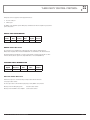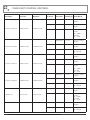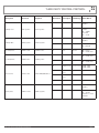
1
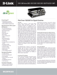
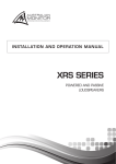
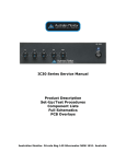
INSTALLATION AND OPERATION MANUAL
AMD SERIES
POWER AMPLIFIER
AMD2100P
AMD2200P
AMD4100P
AMD4200P
IMPORTANT SAFETY INFORMATION
PRÉCAUTIONS DURANT UTILISATION
1. Read these instructions.
1. LISEZ ces instructions.
2. Keep these instructions.
2. Tenez ces instructions.
3. Heed all warnings.
3. Notez tous les avertissements.
4. Follow all instructions.
4. Suivez toutes les avertissements.
5. Do not use this apparatus near water.
5. N’utilisez pas ce produit près de l’eau (la piscine, la plage, le lac, etc.).
6. Clean only with dry cloth.
6. Nettoyez seulement avec une étoffe sèche.
7. Do not block any ventilation openings. Install in accordance with the
manufacturer’s instructions.
7. Ne bloquez aucuns troux de ventilation. Installez en accord avec
les instructions du manufacturier.
8. Do not install near any heat sources such as radiators, heat registers,
stoves, or other apparatus (including amplifiers) that produce heat.
8. N’installez près aucunes sources de chaleur comme radiateurs, registres
de chaleur, fours ou les autres équipements (y compris amplificateurs)
qui produisent la chaleur.
9. Do not defeat the safety purpose of the grounding-type plug.
A grounding type plug has two blades and a third grounding prong.
The wide blade or the third prong are provided for your safety. If the
provided plug does not fit into your outlet, consult an electrician for
replacement of the obsolete outlet.
10. Protect the power cord from being walked on or pinched particularly
at plugs, convenience receptacles, and the point where they exit from
the apparatus.
11. Only use attachments/accessories specified by the manufacturer.
12. Refer all servicing to qualified service personnel. Servicing is required
when the apparatus has been damaged in any way, such as power-supply
cord or plug is damaged, liquid has been spilled or objects have fallen into
the apparatus, the apparatus has been exposed to rain or moisture, does
not operate normally, or has been dropped.
13. This appliance shall not be exposed to dripping or splashing water and
that no object filled with liquid such as vases shall be placed on the
apparatus.
14. Connect the equipment to an appropriate wall outlet that is readily
accessible.
15. The mains plug is used as the disconnect device and shall remain
readily accessible. If the mains plug is not readily accessible due to
mounting in a 19” rack, then the mains plug for the entire rack must
be readily accessible.
16. WARNING: To reduce the risk of fire or electric shock, do not expose this
apparatus to rain or moisture.
17. An appliance with a protective earth terminal should be connected to a
mains outlet with a protective earth connection.
PAGE 2
9. Ne pas tenter de modifier la prise de terre. Une fiche de base type a deux
a deux tranchants et une troisième pointe de base, le tranchant large ou la
troisième pointe est fourni pour votre sécurité. Si la fiche donnée ne
conforme pas votre prise de contact, consultez un électricien pour
remplacement de la prise de contact obsolète.
10. Protegez le cordon de secteur contre être marchée dessus ou pincez
en particulier aux fiches, aux douilles de convenance, et au point où ils
sortent de l’appareil.
11. Seulement utilisez attachements/accessoires spécifiés par le
manufacturier.
12. Référez au personnel qualifié de service pour toutes réparations. La
réparation est donnée quand le système a été endommagé à n’importe
façon, par exemple un fil ou une fiche endommagé(e) de la source
d’alimentation. Avoir été exposé à pluie ou humidité, n’opère pas
normalement, ou avoir été tombé.
13. L’appareil ne doit pas être exposé aux écoulements ou aux éclaboussures
et aucun objet ne contenant de liquide, tel qu’un vase, ne doit être placé
sur l’objet.
14. Branchez l’appareil à une source appropriée et faire que la prise à
débrancher soit facilement accessible.
15. La prise du secteur ne doit pas être obstruée ou doit être facilement
accessible pendant son utilisation. Pour être complètement déconnecté
de l’alimentation d’entrée, la prise doit être débranchée du secteur.
16. AVERTISSEMENT: Pour éviter le risque d’incendie ou de chocs électriques,
ne pas exposer cet appareil à la pluie ou à l’humidité.
17. Un appareil avec la borne de terre de protection doit être connecté au
secteur avec la connexiion de terre de protection.
AMD SERIES INSTALLATION AND OPERATION MANUAL
INTRODUCTION AND CONTENTS
AMD SERIES
INTRODUCTION3
The AMD P series of power amplifiers from Australian Monitor
represent a quantum leap forward in connectivity, controllability &
flexibility in the constant voltage amplifier market. The AMD series
allows contractors to integrate the power amplifier to third party
control systems for remote control and status reporting. The AMD
series amplifiers also offer the flexibility of comprehensive on board
DSP processing and 24VDC back up power.
Australian Monitor AMD P series is the future of constant
voltage amplification.
FRONT PANEL
4
REAR PANEL
5
INSTALLATION6
SOFTWARE APPLICATION
7
THIRD PARTY CONTROL PROTOCOL
11
DIMENSIONS18
SPECIFICATIONS19
Revision 1.2 May 2012
WARNING!
TO PREVENT FIRE OR SHOCK HAZARD, DO NOT USE THE PLUG WITH
AN EXTENSION CORD, RECEPTACLE OR OTHER OUTLET UNLESS THE BLADES
CAN BE FULLY INSERTED TO PREVENT BLADE EXPOSURE.
TO REDUCE THE RISK OF FIRE OR ELECTRIC SHOCK, DO NOT EXPOSE
THIS APPLIANCE TO RAIN OR MOISTURE.
TO PREVENT ELECTRICAL SHOCK, MATCH WIDE BLADE PLUG TO WIDE SLOT, FULLY INSERT.
CAUTION
RISK OF ELECTRIC SHOCK
DO NOT OPEN
The lightning flash with arrowhead symbol,
within an equilateral triangle, is intended
to alert the user to the presence of
uninsulated “dangerous voltage” within
the product’s enclosure that may be of
sufficient magnitude to constitute a risk
of electric shock to persons.
WARNING: TO REDUCE THE RISK
OF ELECTRIC SHOCK, DO NOT
REMOVE COVER (OR BACK).
NO USER SERVICEABLE PARTS INSIDE.
REFER SERVICING TO QUALIFIED
SERVICE PERSONNEL.
The exclamation point within an equilateral
triangle is intended to alert the user to
the presence of important operating and
maintenance (servicing) instructions in the
literature accompanying the appliance.
Rating plate and caution marking are marked on the back enclosure of the apparatus
AMD SERIES INSTALLATION AND OPERATION MANUAL
PAGE 3
FRONT PANEL
1
4 channel model shown here
AMD4100P
SIGNAL
FAULT
CLIP
CHANNEL 1
2
SIGNAL
FAULT
CLIP
CHANNEL 2
SIGNAL
FAULT
CLIP
SIGNAL
FAULT
CHANNEL 3
3
CLIP
CONTROL
CHANNEL 4
4
1 Signal Indicator
The signal indicators (blue) illuminates when audio is present on the relevant
amplifier channel.
2 Fault Indicator
The fault indicators (red) illuminate when a fault is detected on the relevant
amplifier channel.
A fault may be detected due to short circuit conditions or internal failure.
3 Clip Indicator
The clip indicators (red) illuminate when an amplifier channel is approaching full
power or clipping.
If this occurs often, the input source or amplifier gain should be reduced
accordingly. Alternately the compressor block for the effected channel could be
set to avoid the clipping condition.
4 Control Indicator
The control indicator (blue) blinks whenever a third party control system
accesses the amplifier or adjusts an operating parameter.
The control indicator also blink briefly when the amplifier is in the low power
standby mode.
PAGE 4
AMD SERIES INSTALLATION AND OPERATION MANUAL
REAR PANEL
CLASS 2 WIRING
POWER
1
OUTPUT 2
OUTPUT 3
2
VCA 1
CLASS 2 WIRING
0VDC
OUTPUT 4
VCA 2
+24VDC
VCA 3
VCA 4
4 channel model shown here
Made in The Philippines
OUTPUT 1
INPUT 4
LEVEL 4
LEVEL 3
3
1 Mains Input
Mains input is via a 3-pin IEC socket. A mains cable to suit your region is
provided with your Australian Monitor amplifier.
The amplifier may be isolated from the mains supply with the mains switch
provided. All models are internally fused.
The AMD2100P model operates from a wide range supply of 90 to 264VAC
while all remaining models are internally configured for either 115V or 230VAC
operation.
Please contact Australian Monitor should your amplifier need to be changed
from its shipped voltage configuration.
2 Battery Input
24 VDC input for emergency power systems.
INPUT 3
INPUT 2
LEVEL 2
LEVEL 1
INPUT 1
4
ETHERNET
5
6
5 Ethernet Port
The Ethernet port provides PC connectivity for use with the supplied software
application and also remote control and status monitoring for use with third
party control systems.
A pair of LED indicators provide link activity and link speed status feedback.
Modules for both Crestron and AMX control systems are available from the
Australian Monitor web site.
For users of other control systems, please refer to the Third Party Control
Protocol section later in this document for a detailed description of the protocol.
6 Logic Controls
VCA: Remote VCA level controls per channel. An Australian Monitor RC1
remote panel or any 500 kohm potentiometer may be connected between
the GND pin and a VCA pin.
GRN: Low Power Standby Mode. The amplifier will enter low power standby
mode when the GRN pin is connected to the GND pin.
3 Amplifier Outputs
Amplifier outputs are terminated on 5.08” pitch removable connectors.
Mating connectors are provided with your Australian Monitor amplifier.
Each amplifier channel output provides 4 Ohm (voice coil), 70V and 100V
(constant voltage) outputs.
RS232: Serial port for third party control.
Modules for both Crestron and AMX control systems are available from
the Australian Monitor web site.
Refer to the Third Party Control Protocol section later in this document
for detailed description of the protocol.
For each amplifier channel, only one output type should be used. You may use
a different output type for each channel ie. 4 Ohms on Channel 1, 100V on
Channel 2.
Ethernet
Female XLR
4 Amplifier Inputs
Balanced line level XLR inputs. The pin configurations are as per the diagram
to the right.
Input level controls are provided for each input channel.
AMD SERIES INSTALLATION AND OPERATION MANUAL
LINK/ACTIVITY
ON: Link Activity
FLASH: Activity
SPEED
OFF: 10Mbps
ON: 100Mbps
PIN 2
HOT
(+)
PIN 1
GND
PIN 3
COLD
(–)
PAGE 5
INSTALLATION
Unpacking
Every Australian Monitor product is tested and inspected before leaving our factory
and should arrive in perfect condition.
When opening the carton check for any noticeable damage to your Australian
Monitor product. Please notify your Australian Monitor reseller immediately should
any damage be discovered.
Should you ever need to re-ship the amplifier, always use the original packaging
carton and materials.
Mounting
The AMD Series power amplifiers are one rack unit high (1RU) and will fit a standard
EIA 19” rack. A rack rear support bracket is supplied and must be must be installed
when rack mounting the amplifier. The rear support bracket should be installed to
the rack (rear rails) prior to mounting the amplifier. Failure to mount or support the
amplifier correctly may lead to chassis damage which is not covered by warranty.
Typically amplifiers may be stacked directly on top of each other with no need for
spacing between units, unless installed in high ambient temperature environments
were a single rack unit space between amplifiers will assist cooling further.
Cooling
The AMD series power amplifiers utilise fan forced air cooling, with air flowing from
right to left (viewed from the front).
Ensure adequate ventilation and/or heat extraction is provided when rack mounting
the amplifier. Installations with multiple AMD P series amplifiers or other heat
generating equipment with in the same rack will benefit from full rack cooling, using
conventional ducted cool-air fed through the rack base.
For smaller installations or were rack cooling is not possible, ensure the rack
provides free air flow above and below the rack. Also avoid the use of rear doors on
the equipment rack.
Please consider the thermal dissipation figures provided later in this manual when
installing your AMD series amplifier.
Grounding
In the interests of safety, ensure the amplifier is connected to a suitable grounded
mains outlet and NEVER disconnect the earth pin on the AC power cord.
PAGE 6
AMD SERIES INSTALLATION AND OPERATION MANUAL
SOFTWARE APPLICATION
Main Screen
The Main Screen provides an audio matrix for setting up the amplifier input
and output relationship, signal level meters and various amplifier status
indicators.
The audio matrix provides amplifier inputs on each row and amplifier
outputs on each column. A 2x2 matrix is presented when connected to
2 channel amplifiers and a 4x4 matrix is presented when connected to
4 channel amplifiers. By default all models are configured 1:1 with input
1 routed to output 1, and so on.
The Master Output section provides real time graduated level meters for
each amplifier channel. The meters display the DSP output level in dBFS
(dB below Full Scale).
The current VCA attenuation level is displayed for each amplifier channel in
real time in the VCA Levels section.
The Amplifier Status section provides fault and thermal status indications
for each amplifier channel, plus an amplifier standby (low power) status
indicator.
The Audio Setup button opens the Audio Setup page, providing access to
the various DSP functions and settings.
Audio Setup
The Audio Setup page provides a block diagram of the amplifier audio
chain, with inputs on the left hand side, VCA and DSP functions in the
centre and amplifier outputs on the right hand side.
The amplifier inputs and outputs may be renamed as desired by clicking
on the input or output name (see below).
Each external VCA may be individually enabled or disabled using the VCA
Enable buttons.
Input / Output Names
The amplifier inputs and outputs may be renamed as desired by clicking
on the input or output name. Input/Output names may be freely defined
with a maximum of 15 characters permitted.
AMD SERIES INSTALLATION AND OPERATION MANUAL
PAGE 7
SOFTWARE APPLICATION
Crossover / EQ
The Crossover / EQ block allows the user to enable and adjust crossover
and EQ functions for each amplifier output channel.
The crossover block provides High Pass, All Pass and Low Pass filters
with adjustable frequency and filter types.
The EQ section provides Low Shelf, High Shelf and 4 Bell (parametric)
filters with adjustable Frequency, Gain and Quality Factor (Bell only).
Delay
The Delay block allows the user to apply a fixed delay to an amplifier
output.
The delay period may be defined as Milliseconds, Samples or Distance
in Meters or Feet.
The maximum delay time provided is 124.00mS (42.90 meters).
Dynamics
The Dynamics block allows the user to adjust a compressor for each
amplifier output.
The compressor provides adjustment of Threshold, Ratio, Make Up Gain,
Attack and Release parameters.
Input level and Gain Reduction meters provide real time feedback
of the compressor function.
An input/output graph provides a visual representation of the configured
compressor threshold and compression slope.
PAGE 8
AMD SERIES INSTALLATION AND OPERATION MANUAL
SOFTWARE APPLICATION
Output
The output block allows the user to trim the output level of each amplifier
channel.
Mute and Phase Invert controls are also provided.
A signal level meter provides real time indication of the audio output for
the relevant output channel, displayed in dBFS.
Choose Device Type
The device chooser dialog is presented when the software application is
first launched, or when defining a new configuration (File/New on the main
menu).
When presented, select the amplifier model you wish to connect to or
create a new configuration for. The GUI will adapt accordingly presenting
a 2 channel or 4 channel layout.
Choose Network
Before connecting to a AMD P series amplifier, open the Choose Network
Adapter dialog by selecting Device/Network Interface from the main menu
and select the connected physical network adapter from the presented list
of discovered network interfaces.
The Local Area Connection is typically used for wired connections to your
P series amplifier.
AMD SERIES INSTALLATION AND OPERATION MANUAL
PAGE 9
SOFTWARE APPLICATION
Go Online
The Go Online dialog is presented when selecting Device/Go Online from
the main menu, or when selecting the Go Online button at the bottom left
of the main page.
Once initiated, the auto discovery mechanism will search for AMD P Series
amplifiers connected to the wired network.
The user may connect to a discovered device by selecting the device in
the Discovered Devices window followed by pressing the Connect button.
Note: The PC network interface and amplifiers must be on the same
network subnet for discovery and connections with the GUI to function.
The user may simply enter a known amplifier IP address in the IP Address
field and connect without performing a discovery first.
The IP address details for selected device may be edited by pressing the
Edit Dev IP button.
Edit Dev IP
The IP address details for a connected amplifier may be edited by
selecting the Edit Dev IP button on the Go Online connection dialog.
The user may edit the device IP Address, Subnet Mask and Default
Gateway.
When defining a Default Gateway address, be sure the Gateway Address
is on the same subnet as the new Device IP Address.
PAGE 10
AMD SERIES INSTALLATION AND OPERATION MANUAL
THIRD PARTY CONTROL PROTOCOL
Third party control is supported via two physical interfaces:
1. RS-232 serial port
2. Ethernet port
The AMD P Series amplifiers provide third party communications when the amplifier is placed in the
power saving mode.
RS-232 PORT INFORMATION
Baud
Rate
Data
Bits
Parity
Stop
Bits
Duplex
Flow
Control
19,200
8
None
1
Full
None
RS-232 Packet Structure
The serial protocol is an ASCII protocol. All characters in the string are ASCII characters.
Binary values ranging between hexadecimal 00 and FF are transmitted as two ASCII characters.
All command strings start with the % character and end with a carriage return (shown as <CR>
in this document) and are equal to the single ASCII value of 13 decimal (0x0D hex).
ETHERNET PORT INFORMATION
Port
Speed
Protocol
Receive
Port
Transmit
Port
Duplex
10/100Mbps
UDP
11223
11224
Full
Ethernet Packet Structure
Ethernet messages are constructed using a simple header and data structure:
<message header><data>
The message header is either a Master (3rd party) or Slave (AMD P series) Header.
Messages from the third party system: <master header><data>
Messages from the AMD P series amplifier: <slave header><data>
AMD SERIES INSTALLATION AND OPERATION MANUAL
PAGE 11
THIRD PARTY CONTROL PROTOCOL
Packet Header
The header for each packet is 10 bytes in length and consists of the following:
UInt16 ProtocolId = 0x5E03;
UInt16 SubType = 0x0001;
UInt16 SequenceNumber = 0x0001 to 0xFFFF;
UInt16 Reserved = 0x0000;
UInt16 ChunkLength = Length (in bytes) of data after this header
The Protocol field differentiates this packet from others with a similar format for other products.
The value is specific to the AMD P Series amplifier.
The SubType field should be set to 0x0001 for all packets originating from a controller (or master).
The amplifier, in its reply packets, will have this field set to 0x0100.
The SequenceNumber is a field that can be used by masters to place a unique ID on the packet.
The amplifier will reply to a particular command with a matching SequenceNumber such that a
master could ensure that a reply was for a specific request.
The Reserved field should be set to 0x0000.
Lastly, the ChunkLength field contains the length of ALL SUBSEQUENT data in the packet (in bytes).
Data chunks following the header are restricted to 272 bytes.
NOTE: Due to the lossy nature of UDP and the fact that the amplifier can support communication
with multiple masters at the same time; masters should continually poll for changes in hardware
state.
Message Protocol
The following amplifier parameters may be set and read from the unit:
➢
Channel input cross-mix level
➢
Channel input cross-mix mute
➢
Channel output mute
➢
Channel output level
➢
Standby mode
The following status information may be requested:
➢
Version information
➢
Amplifier status
NOTE: For two channel amplifier, commands received with reference to channel 3 or 4
will be ignored.
PAGE 12
AMD SERIES INSTALLATION AND OPERATION MANUAL
THIRD PARTY CONTROL PROTOCOL
Command: Channel Input Cross Mix Level (PCML)
This command is used to get/set the level of an input to an amplifier channel.
%PCML:xyzz<CR>
Where x is output channel to select (between 1 and 4) and y is the input channel (between 1 and 4).
For volume parameters, the zz section of the command can range between 0x00 (muted) and 0xE1
(225 = +12dB of gain). This allows half dB steps, where 1 = -100dB, C9 (201) = 0dB and E1 (225)
= 12dB.
e.g. %PCML:11C9<CR> sets the level routed from input 1 to output channel 1 to unity.
e.g. %PCML:42BD<CR> sets the level routed from input 2 to output channel 4 to -6dB.
When the value has been changed (from either GUI or external comms), or the current value has
been requested, the amplifier will send:
%PCML=xyzz<CR> where x, y and zz are as per above.
To request the current value of a cross-mix level, use:
%PCML:xy??<CR>
Command: Channel Input Cross Mix Mute (PCMM)
This command is used to get/set the mute state of an input to an amplifier channel.
%PCMM:xyzz<CR>
Where x is output channel to select (between 1 and 4) and y is the input channel (between 1 and 4).
For mute parameters, the zz section of the command can range between 00 (mute off) and 01
(mute on).
e.g. %PCMM:1100<CR> sets the mute state of input 1 to output channel 1 to unmuted.
e.g. %PCMM:4201<CR> sets the mute state of input 2 to output channel 4 to muted.
When the value has been changed (from either GUI or external comms), or the current value has
been requested, the amplifier will send:
%PCMM=xyzz<CR> where x, y and zz are as per above.
To request the current value of a cross-mix mute state, use:
%PCMM:xy??<CR>
AMD SERIES INSTALLATION AND OPERATION MANUAL
PAGE 13
THIRD PARTY CONTROL PROTOCOL
Command: Channel Output Level (PLVL)
This command is used to get/set the level of an amplifier output channel.
%PLVL:xyy<CR>
Where x is output channel to select (between 1 and 4).
For volume parameters, the yy section of the command can range between 0x00 (muted) and 0xE1
(225 = +12dB of gain). This allows half dB steps, where 1 = -100dB, C9 (201) = 0dB and E1 (225)
= 12dB.
e.g. %PLVL:1C9<CR> sets the level of amplifier channel 1 to unity.
e.g. %PLVL:2BD<CR> sets the level of amplifier channel 2 to -6dB.
When the value has been changed (from either GUI or external comms), or the current value has
been requested, the amplifier will send:
%PLVL=xyy<CR> where x and yy are as per above.
To request the current value of an output level, use:
%PLVL:x??<CR>
Command: Channel Output Mute (PMUT)
This command is used to get/set the mute state of an amplifier output channel.
%PMUT:xyy<CR>
Where x is output channel to select (between 1 and 4).
For mute parameters, the yy section of the command can range between 00 (mute off) and 01
(mute on).
e.g. %PMUT:100<CR> sets the mute state of output channel 1 to unmuted.
e.g. %PMUT:201<CR> sets the mute state of output channel 2 to muted.
When the value has been changed (from either GUI or external comms), or the current value has
been requested, the amplifier will send:
%PMUT=xyy<CR> where x and yy are as per above.
To request the current value of the output mute state, use:
%PMUT:x??<CR>
PAGE 14
AMD SERIES INSTALLATION AND OPERATION MANUAL
THIRD PARTY CONTROL PROTOCOL
Command: Standby Mode (PGRN)
This command is used to get/set whether or not the amplifier is in Standby (power-saving) mode.
In this mode, the amplifier is shutdown. This parameter operates in a logic OR fashion with the rear
panel Standby input. If either the rear panel input is active or this parameter is active, Standby mode
is active.
%PGRN:xx<CR>
If xx = 00, then Standby mode is de-activated and the amplifier operates as normal. If xx = 01,
then Standby mode is activated.
When Standby mode has been changed (from either GUI or external comms), or the current
value has been requested, the amplifier will send:
%PGRN=xx<CR>
Where the return values are:
➢
00 = Normal mode
➢
01 = Standby mode
To request the current value, use:
%PGRN:??<CR>
Command: Amp Status (PAMP)
This command is used to get the status of an amplifier.
%PAMP:x??<CR>
Where x is the amplifier to select (between 1 and 4). The AMDXY00P will reply with:
%PAMP=xyy<CR>
When the AMDXY00P replies, the yy section of the command can range between 00 and 02.
These values should be interpreted as:
➢
0x00 = Amplifier OK
➢
0x01 = Amplifier in thermal shutdown
➢
0x02 = Amplifier in fault shutdown
NOTE: that this command must be polled; the amplifier will not send out amplifier status
information on the RS232 port unless explicitly requested by sending the command.
Command: Version Info (PVER)
This command is used to get the device and firmware information.
%PVER:??<CR>
The amplifier will reply with:
%PVER=AMDXY00P,aabbcccc<CR>
Where XY can be 21, 22, 41 or 42 and represents the device model.
aa is the firmware major version number (can range from 0x00 to 0xFF).
bb is the firmware minor version number (can range from 0x00 to 0xFF).
cccc is the firmware revision version number (can range from 0x0000 to 0xFFFF).
AMD SERIES INSTALLATION AND OPERATION MANUAL
PAGE 15
THIRD PARTY CONTROL PROTOCOL
Description
Get Input Cross-Mix Level
Command
%PCML:xy??<CR>
Response
%PCML=xyzz<CR>
Parameter
Description
Valid Range
Value Detail
x
Output Channel
1, 2, 3 or 4
1 or 2 for 2 channel
amplifiers
y
Input Channel
1, 2, 3 or 4
1 or 2 for 2 channel
amplifiers
zz
Mix Level
00 to E1 hex
0.5dB steps where for
example
01 = -100dB
C9 = 0dB
E1 = +12dB
Get Input Cross-Mix Mute
Set Input Cross-Mix Level
%PCMM:xy??<CR>
%PCML:xyzz<CR>
%PCMM=xyzz<CR>
%PCML=xyzz<CR>
x
Output Channel
1, 2, 3 or 4
1 or 2 for 2 channel
amplifiers
y
Input Channel
1, 2, 3 or 4
1 or 2 for 2 channel
amplifiers
zz
Mute on/off
00 or 01
00 = Mute OFF
01 = Mute ON
x
Output Channel
1, 2, 3 or 4
1 or 2 for 2 channel
amplifiers
y
Input Channel
1, 2, 3 or 4
1 or 2 for 2 channel
amplifiers
zz
Mix Level
00 to E1 hex
0.5dB steps where for
example
01 = -100dB
C9 = 0dB
E1 = +12dB
Set Input Cross-Mix Mute
%PCMM:xyzz<CR>
%PCMM=xyzz<CR>
Get Output Level
%PLVL:x??<CR>
%PLVL=xyy<CR>
Get Output Mute
%PMUT:x??<CR>
%PMUT=xyy<CR>
PAGE 16
x
Output Channel
1, 2, 3 or 4
1 or 2 for 2 channel
amplifiers
y
Input Channel
1, 2, 3 or 4
1 or 2 for 2 channel
amplifiers
zz
Mute on/off
00 or 01
00 = Mute OFF
01 = Mute ON
x
Output Channel
1, 2, 3 or 4
1 or 2 for 2 channel
amplifiers
yy
Output Level
00 to E1 hex
0.5dB steps where for
example
01 = -100dB
C9 = 0dB
E1 = +12dB
x
Output Channel
1, 2, 3 or 4
1 or 2 for 2 channel
amplifiers
yy
Mute on/off
00 or 01
00 = Mute OFF
01 = Mute ON
AMD SERIES INSTALLATION AND OPERATION MANUAL
THIRD PARTY CONTROL PROTOCOL
Description
Set Output Level
Command
%PLVL:xyy<CR>
Response
%PLVL=xyy<CR>
Set Output Mute
%PMUT:xyy<CR>
%PMUT=xyy<CR>
Get Standby Mode %PGRN:??<CR> %PGRN=xx<CR>
Set Standby Mode
Get Version Info
Get Amp Status
%PGRN:xx<CR>
%PVER:??<CR>
%PAMP:x??<CR>
AMD SERIES INSTALLATION AND OPERATION MANUAL
%PGRN=yy<CR>
%PVER=AMDxy00P,aabbcccc
%PAMP=xyy<CR>
Parameter
Description
Valid Range
Value Detail
x
Output Channel
1, 2, 3 or 4
1 or 2 for 2 channel
amplifiers
yy
Output Level
00 to E1 hex
0.5dB steps where for
example:
01 = -100dB
C9 = 0dB
E1 = +12dB
x
Output Channel
1, 2, 3 or 4
1 or 2 for 2 channel
amplifiers
yy
Mute on/off
00 or 01
00 = Mute OFF
01 = Mute ON
xx
Mode
00 or 01
xx
Mode
00 or 01
00 = Normal
01 = Standby mode
yy
Mode
00 or 01
00 = Normal
01 = Standby mode
xy
Amplifier model
21, 22, 41 or 42 2100P, 2200P,
4100P, 4200P
aa
FW Version
major
bb
FW Version
minor
cccc
FW Revision
x
Output Channel
1, 2, 3 or 4
1 or 2 for 2 channel
amplifiers
yy
Status byte
00, 01 or 02
00 = Ok
01 = Thermal
Shutdown 2 = Fault
Shutdown
00 = Normal
01 = Standby mode
PAGE 17
DIMENSIONS
43.60 mm
(1.71”)
32.00 mm
(1.25”)
482.00 mm (19.0”)
465.00 mm (18.3”)
AMD4100P
SIGNAL
FAULT
CLIP
SIGNAL
FAULT
CHANNEL 1
CLIP
SIGNAL
FAULT
CHANNEL 2
CLIP
SIGNAL
FAULT
CHANNEL 3
CLIP
CONTROL
CHANNEL 4
CLASS 2 WIRING
POWER
OUTPUT 3
VCA 1
CLASS 2 WIRING
0VDC
OUTPUT 4
VCA 2
+24VDC
VCA 3
Made in The Philippines
VCA 4
433.00 mm (17.0”)
OUTPUT 2
OUTPUT 1
INPUT 4
LEVEL 4
LEVEL 3
INPUT 3
INPUT 2
LEVEL 2
LEVEL 1
INPUT 1
ETHERNET
442.00 mm (17.40”)
PAGE 18
AMD SERIES INSTALLATION AND OPERATION MANUAL
SPECIFICATIONS
AMD2100P
AMD2200P
AMD4100P
AMD4200P
Power Output
4 ohm
100W (20 Vrms)
200W (28.3 Vrms)
100W (20 Vrms)
200W (28.3 Vrms)
70 V
100W (49 Ohms)
200W (25 Ohms)
100W (49 Ohms)
200W (25 Ohms)
100 V
100W (100 Ohms)
200W (50 Ohms)
100W (100 Ohms)
200W (50 Ohms)
Power Consumption
Standby
7 W
12 W
12 W
13 W
Idle
11 W
20 W
20 W
30 W
1/8 power
48 W
92 W
92 W
160 W
1/3 power
107 W
204 W
204 W
364 W
Thermal Dissipation
Standby
7W (23.88 Btu/Hr)
12W (40.94 Btu/Hr)
12W (40.94 Btu/Hr)
13W (44.36 Btu/Hr)
Idle
11W (38.53 Btu/Hr)
20W (68.24 Btu/Hr)
20W (68.24 Btu/Hr)
30W (102.36 Btu/Hr)
1/8 power
23W (78.48BTu/Hr)
67W (228.60 BTu/Hr)
67W (228.60 BTu/Hr)
135W (460.62 BTu/Hr)
1/3 power
40W (137.62 Btu/Hr)
137W (468.58 Btu/Hr)
137W (468.58 Btu/Hr)
297W (1014.50 Btu/Hr)
Net Weight
10kg (22.0lb)
11kg (24.2lb)
13kg (28.6lb)
16kg (35.2lb)
Shipping Weight
13kg (28.6lb)
15kg (33.0lb)
16kg (35.2lb)
19kg (41.8lb)
Frequency Response
Total Harmonic Distortion
Input Impedance
SpecificationConditions
70Hz - 20kHz, ±3 dB
Signal Input 2 dB below clip
< 0.6dB
Signal Input 2 dB below clip
11 kOhms
Nominal Input
+1 dBu
Rear panel level controls at maximum,
DSP bypassed
Crosstalk
> 60dB
1 kHz, maximum output
S/N Ratio
> 100dB
A-weighted, 20 Hz to 20 kHz
Power Source
Recommended Operating Temp
Recommended Operating Humidity
AC Mains (110-120 V 60Hz / 220-240 V 50Hz)
Factory Configured
24VDC Battery Backup
10° C to 45° C (50° F to 113° F)
5 % to 95 % non-condensing
Dimensions (w x d x h)
433 mm x 442 mm x 43.6 mm
(17.0” x 17.4” x 1.7”)
Shipping Dimmensions (w x d x h)
555 mm x 555 mm x 170 mm
(22” x 22” x 6.7”)
AMD SERIES INSTALLATION AND OPERATION MANUAL
Not including rack ears or
rear panel connectors
PAGE 19
AUSTRALIAN MONITOR
Address: 1 Clyde Street, Silverwater, Sydney NSW 2128 Australia. Private Bag 149, Silverwater NSW 1811 ACN 007 573 417
Website: www.australianmonitor.com.au International enquiries email: [email protected]
DISTRIBUTED IN AUSTRALIA AND NEW ZEALAND BY HILLS SVL www.hillssvl.com.au
NSW P: 02 9647 1411
E: [email protected]
QLD
ACT
P: 07 3852 1312
P: 02 6260 4544
E: [email protected] E: [email protected]
WA
P: 08 9204 0200
E: [email protected]
VIC
P: 03 9890 7477
E: [email protected]
SA
NZ
P: 08 8408 8300
P: 09 415 9426
E: [email protected] E: [email protected]