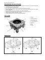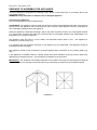
1
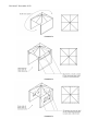
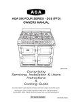
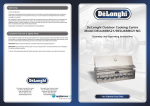
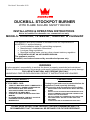
Revision 2 November 2012 DUCKBILL STOCKPOT BURNER WITH FLAME FAILURE SAFETY DEVICE INSTALLATION & OPERATING INSTRUCTIONS Not to be installed for domestic use, commercial use only MODELS: Y018LPWF, Y018NGWF, Y028LPWF & Y028NGWF The appliance should be installed in accordance with the requirements of AS/NZS5601.1 and the following: Local installation codes for gas building equipment; Manufacturer’s installation instructions; Local gas fitting regulations; Municipal building codes; and any other relevant statutory regulation. TO BE INSTALLED BY AN AUTHORIZED PERSON The appliance must be: Installed, serviced and removed by an authorised person only. WARNING It is the operator’s responsibility to see that the burner is properly assembled and maintained. Failure to follow instructions in this manual could result in physical injury and/or property damage. FOR USE WITH NATURAL AND PROPANE GAS ONLY HAZARDOUS FIRE OR EXPLOSION MAY RESULT IF INSTRUCTIONS ARE IGNORED. PRECAUTIONS FOR YOUR SAFETY IF YOU SMELL GAS: TURN OFF MAIN GAS SUPPLY IMMEDIATELY EXTINGUISH ALL NAKED FLAMES AND DO NOT OPERATE ANY ELECTRICAL APPLIANCES NEAR THIS APPLIANCE VENTILATE THE AREA WELL CHECK FOR LEAKS AS DETAILED IN THIS MANUAL IF ODOUR PERSISTS, CONTACT PLACE OF PURCHASE OR GAS SUPPLIER IMMEDIATELY Testing for gas leaks must be checked before the appliance is used especially following disconnection and reconnection of the cylinder NEVER CHECK FOR LEAKS WITH A MATCH OR OPEN FLAME DO NOT STORE OR USE PETROLEUM PRODUCTS OR OTHER FLAMMABLE VAPOURS AND LIQUIDS IN THE VICINITY OF THIS APPLIANCE AN LP CYLINDER NOT CONNECTED FOR USE IN THIS APPLIANCE SHALL NOT BE STORED NEAR THIS APPLIANCE TO BE INSTALLED ON A FIREPROOF BASE ONLY PLEASE READ INSTRUCTIONS CAREFULLY BEFORE ASSEMBLING AND IT IS RECOMMENDED THAT THIS MANUAL BE RETAINED FOR FUTURE REFERENCE. Revision 2 November 2012 IMPORTANT Read the following instructions carefully and be sure your appliance is properly installed, assembled and cared for. Failure to follow these instructions may result in serious bodily injury and/or property damage. This appliance is intended for commercial use only. This appliance is adjusted to operate on the gas specified on the gas type label and on the data label. The gas type label is located front of the appliance and data label RH side front of the appliance. If in doubt as to the type of gas available contact the network operator or gas supplier for confirmation of gas type. It is the operator’s responsibility to check the appliance is properly assembled and maintained The heat shield located beneath the burner must always be in place during burner operation. Do not lay the gas cylinder down – cylinder should be stored / used in the upright position Hazardous fire or explosion may result if instructions are ignored. Leak test all connections before use and after each cylinder refill Never check for leaks with a match or naked flame DO NOT PLACE ARTICLES ON OR AGAINST THIS APPLIANCE. DO NOT USE OR STORE FLAMMABLE MATERIALS NEAR THIS APPLIANCE. DO NOT SPRAY AEROSOLS IN THE VICINITY OF THIS APPLIANCE WHILE IT IS IN OPERATION. Use only in well ventilated areas, but not facing against any draught. WARNING! Carbon monoxide hazard – this appliance can produce carbon monoxide which has no odour. Using the appliance in an enclosed space (for example, boats, caravan, tent, car, and mobile home) may cause death. Do not move the appliance during operation Avoid twisting or kinking of the flexible gas hose Do not use the appliance near any air opening(s) into buildings (i.e. windows, doorways, ventilation ducts etc.) Leak test all connections before use and after each cylinder refill – refer “How to Check for Gas Leaks” in this manual. An LP gas cylinder not connected for use in this appliance shall not be stored near this appliance. Ensure the gas hose is not placed under the appliance or allowed to contact any hot surfaces of the appliance This appliance must not be modified or changed in any way. Disconnect the gas cylinder from the burner prior to storage. It is also recommended that the gas cylinder be stored outdoors in a well-ventilated area. Do not use any other gas type except the one specified on the label/data plate. Use only the gas regulator and hose supplied with this appliance. An inferior or a damaged regulator could cause an incomplete combustion or other troubles with the burner. Do not leave the burner unattended when in use. Always turn off the burner and the main gas valve after each use. Do not use the burner as a space heater under any circumstance. Do not cover or blow off the flames. This could cause gas leaking. Always keep inflammable materials away from the burner. Make sure that you use cooking woks, pots or pans that sit firmly on the trivet. Do not use pots that are too small / large for the burner size, as they could be unstable on the trivet. If abnormal combustion is observed when in use, turn off the main gas valve and examine the burner (Refer to Trouble-Shooting Guide). Do not attempt to repair the burner yourself. Do not install into a marine environment. This appliance is suitably protected while it is on its way to you. All materials used for packaging are suitable for recycling. Please make a contribution to protecting the environment by disposing of the packaging appropriately HOW TO CHECK FOR GAS LEAKS To check for leaks, turn on gas supply with the appliance gas valves in the OFF position (DO NOT IGNIGHT) Check for leakage by brushing a solution of soapy detergent and water onto the connection points at the bottle and the appliance. If bubbling is evident (it may take more than 30 seconds to appear) this indicates a gas leak is present. If disassembling, cleaning, reassembling and tightening the connection does not rectify the leak you should close the gas cylinder valve and consult the place of purchase for assistance. Revision 2 November 2012 PROCEDURES FOR GAS LEAKAGE The strong and distinctive odour of gas may make you aware of a gas leak. If you suspect a gas leak: Immediately turn off the main gas supply. Turn off all appliances and pilot lights; Do not allow gas to build up in the area. Open all the windows and doors. Do not use any naked flame or other ignition source (such as light switches, power points, mobile phones and pagers); Do not operate any electrical equipment in the vicinity of a gas leak; Contact your licensed gas fitter to repair the leak and re-light the appliance. NEVER attempt to repair the appliance yourself. IT MUST BE SERVICED BY AN AUTHORIZED PERSON. PART INDEX 1. Burner 2. Safety Switch ‘A’ 3. Piezo Igniter ‘B’ 4. Control Handle ‘C’ 5. Gas Inlet 6. Body 7. Trivet DIMENSIONS Y018 Series Y028 Series Revision 2 November 2012 PREPARE TO ASSEMBLE THE APPLIANCE Check for damage on the appliance. If damage occurs, please contact Austcrown or your dealer. Do not use a damaged appliance. WARNING! It may hazardous to attempt to use a damaged appliance. Positioning the Appliance Only use the appliance in well ventilated areas. CLEARANCE: The appliance must be sited with at least a 1000 mm gap between both sides, from the front and the rear of the appliance and at least 2700 mm from the trivet of the appliance and any combustible or non-combustible materials above the appliance. When the appliance is assembled abutting a side or rear wall, the wall must be of non-combustible material, e.g. ceramic tiles. If surrounding walls are constructed with a combustible material, refer AS/NZS5601.1 for information on the clearance required. The appliance must be used on a level, stable, non-flammable surface when in use. This appliance is intended for commercial use only. It is important that the ventilation openings of the appliance are not obstructed. The appliance should be protected from direct draughts. The appliance should not be positioned or protected against direct penetration by any trickling water (e.g. rain). If the appliance is installed outdoors, a proper shelter with good ventilation should be used to protect the appliance from draughts and rain. Some examples of shelters are shown below, IMPORTANT: The dimension and building materials of the shelter must meet the requirements mentioned above, or contact your gas filter / local Gas Authority for information on clearances and material required EXAMPLE 1 Revision 2 November 2012 EXAMPLE 2 EXAMPLE 3 EXAMPLE 4 Revision 2 November 2012 Gas Type and Gas Pressure Do not use any other gas type except the one specified on the data label. For LP Gas Model (Supplied with regulator type 73-1-8 AGA 3884 and Hose TPA type APH801 6356) This model of appliance is suitable for use with propane gas and are set to operate under gas pressure of 2.75kPa. *The LP gas regulator and hose supplied are for outdoor installations only. Indoor installations must be installed in accordance with the requirements of AS/NZS5601.1, Local State and Territory regulations, municipal building codes, and any other relevant statutory regulations. For Natural Gas Model (Supplied with Bromic type 980L regulator AGA 5862) This model of appliance is only suitable for use with natural gas and are set to operate under gas pressure of .90kPa. WARNING! It is hazardous to attempt to use other types of gas with this appliance. The Gas Inlet is located for model Y028NGWF/Y028LPWF 300mm up from the base and 25mm in from the RH side leg. For model Y018NGWF/Y018LPWF the gas inlet is located 260mm up from the base and in line with the RH leg side. Gas Cylinder (For LP Gas Model only) Only cylinders which comply with AS2030.1 should be used. The appliance is suitable for use with gas cylinders of 3.9 kg or greater. The gas cylinder should not be dropped or handled roughly! If the appliance is not in use, the cylinder must be disconnected. Replace the protective cap on the cylinder after disconnecting the cylinder from the stove. WARNING! It may hazardous to use a damaged or dented gas cylinder. Cylinders must be stored outdoors in an upright position and out of the reach of children. The cylinder must never be stored under direct sunlight or where temperatures can reach over 50C. Do not store the cylinder near flames, pilot lights or other sources of ignition. DO NOT SMOKE around the cylinders. WARNING! It may hazardous to store gas cylinder in an enclosed place. Exchanging of the gas cylinder Ensure the valve on the cylinder is closed. Remove the hose assembly. Connect in reverse order and check for gas leakage at all joints with soapy water. Gas Hose Assembly Use only the hose assembly supplied with the appliance. Use only a gas hose that complies with AS/NZS1869. The appliance requires a ‘Class B’ Gas hose. The hose should be secured to the regulator and the appliance with spanner. Use the hose with the right threads, DO NOT use adaptors. Inspect the hose assembly before each use of the appliance. The life expectancy of the hose is estimated at 5 years. It is recommended that the hose is changed every 5 years. The use of the wrong hose is unsafe. Always check that you have the correct items before operating the appliance. WARNING! It may hazardous to use the wrong type of hose. The length of the hose must not excess 1.8 metres (maximum). Worn or damaged hose must be replaced if there is evidence of excessive abrasion or wear. A replacement hose is supplied by Austcrown, refer to contact detail. Ensure that the hose is not obstructed, kinked, or in contact with any part of the appliance other than at its connection. WARNING! It may hazardous to use a damaged hose. Regulator Use only the gas regulator supplied with the appliance which complies with AS4618. The appliance must be used with a LOW pressure regulator with output pressure of 2.75kPa for LP gas and 0.90kPa for Natural Gas. Use a regulator with the right threads. For Propane Gas Model: 73-1-8, AGA 3884 Outlet Pressure: 2.75kPa Flow Capacity: 3kg/hr (For Y018LPWF) Flow Capacity: 10kg/hr (For Y028LPWF) Inlet Fitting: CGA-510 POL with Soft Nose Outlet Fitting: 3/8” BSPF Thread For Natural Gas Model: Bromic 980L, AGA 5862 Outlet Pressure: 0.90kPa Flow Capacity: 2 M3/hr (For Y018NGWF) Flow Capacity: 3 M3/hr (For Y028NGWF) Inlet Fitting: ½” BSPF Thread Outlet Fitting: ½” BSPF Thread Revision 2 November 2012 WARNING! It may hazardous to use the wrong type of regulator. Storage of Appliance Always wait for the appliance to cool down before attempting to transport or store. Storage of an appliance for transport or indoors is only permissible if the cylinder is disconnected and removed from the appliance. When the appliance is not being used for a period of time it should be stored in a dry dust free environment. INSTALLATION 1. Open carton and take out the appliance (CAUTION: VERY HEAVY! SHOULD BE LIFTED BY TWO PEOPLE). Check carefully for any damage on the appliance; call your dealer if damage occurred. DO NOT install damaged appliance. 2. Find a well ventilated and level place to install the appliance. The appliance is fitted with 4 adjustable legs. Place the appliance on a flat base and adjust legs to maintain a level cooking surface. 3. A LOW PRESSURE regulator MUST BE used with this the appliance. (Details refer to Regulator in the “PREPARE TO ASSEMBLE THE APPLIANCE” section) 4. The gas inlet is located at the rear right hand side of the appliance. The gas inlet fitting is ½” BSPF for Natural Gas Model and CGA-510 POL with Soft Nose for LPG Model. 5. Connect the gas inlet to the main gas supply in accordance to Australia Standard. If a flexible hose is to be used, DO NOT assemble beneath the appliance, under direct sunlight or close to other sources of heat. 6. The length of connection between the appliance and the main gas supply should not exceed 1.8m. 7. Check for gas leakage at all joints with soapy water or other approved methods. UNDER NO CIRCUMSTANCES SHOULD A NAKED FLAME BE USED IN CHECKING FOR GAS LEAKS. OPERATING INSTRUCTIONS Ignite the Burner 1. Ensure the Control Handle (C) is at ‘OFF’ position. 2. Turn on the main gas supply. 3. Press and Hold Switch (A) down. 4. Press Switch (B) down, to ignite the pilot flame. Release Switch (B) 5. Repeat Step 4 until the pilot flame is alight. 6. Continue to hold down Switch (A) for 10 second, and then release. 7. Repeat Step 1 – 6 if pilot fails to stay alight. 8. Turn Handle (C) to ‘ON’ position. Turn off Burner 1. Turn Control Handle (B) to ‘OFF’ position. 2. Turn off main gas supply. ABNORMAL OPERATION You should cease using the appliance and seek service from an authorised agent if any of the following are observed during operation of the appliance: Carbon Build up on the appliance or pans, Excessive yellow tipping of the burner flame, Flame lifting off the burner ports or flashing back. Flame abnormality may be due to gas supply restriction or blockage of burner ports or venturi. Gas spillage may occur if the burner inlet is partially blocked. The gas may ignite around the burner inlet. It is recommended that an authorised person/service agent perform all maintenance. Revision 2 November 2012 If the burner fails to operate correctly, contact place of purchase or authorised agent for advice and service. RECOMMENDED POT SIZE Y018 Series — Minimum: Ø44cm, Maximum: Ø49cm Y028 Series — Minimum: Ø44cm, Maximum: Ø61cm CAUTION Revision 2 November 2012 MAINTENANCE Do not touch hot surfaces. Do not attempt any cleaning or maintenance within 30 minutes of the appliance being used. Periodic maintenance should be performed at intervals not exceeding 6 months or when evident such as with flame abnormality or burner discolouration. Flame abnormality or burner discolouration is generally a sign of gas supply restriction or blocked burner ports. The pilot provides a flame to light the main burner. If the pilot is blocked by debris, spider webs, etc., the pilot flame may be too small resulting in erratic ignition of the main burner. If this occurs, it will be necessary to clean the pilot with compressed air. It is recommended that an authorised person perform all maintenance. If the appliance fails to operate normally, contact the place of purchase, or their authorised agent for advice and service. DO NOT ATTEMPT REPAIRS YOURSELF. It is also recommended that the hose assembly and regulator inlet fitting seals be checked for damage, abrasion, cracking or displacement before each use. PVC hose assemblies may harden with age and should be replaced if this occurs. If a replacement part or assembly is required please contact place of purchase or authorized service agent for advice. TROUBLESHOOTING . DO NOT MODIFY THIS APPLIANCE. If the appliance cannot be adjusted to perform correctly contact after sales service contact details this page. Problem No Ignition Possible Cause Main Gas Valve is not turned on. Solution Turn off the gas valve once and then turn it on fully. Air trapped in the gas hose. Repeat the ignition process until all air in the hose is purged completely. The safety valve is not open. Follow the procedures from 1 to 6 in the section of “Ignite the burner”. Contact your dealer for a service/repair. DO NOT ATTEMPT TO REPAIR IT YOURSELF. Clean the injector. Gas Leaking Failure of the gas valve. Incomplete Combustion (Yellow Flame) Injector is clogged. SPECIFICATIONS Product Name 18 Jet Duckbill Burner Cooker 28 Jet Duckbill Burner Cooker Model No. Y018LPWF Y018NGWF Y028LPWF Y028NGWF Gas Type Propane Natural Propane Natural Gas Pressure 2.75kPa 0.90kPa 2.75kPa 0.90kPa Injector Size Ø0.58mm Ø0.98mm Ø0.58mm Ø0.98mm Gas Consumption 1.34kg/hr 1.76m³/hr 2.08kg/hr 2.74m³/hr CGA-510 POL with Soft Nose ½” BSPF CGA-510 POL with Soft Nose ½” BSPF Inlet Fitting Heat Capacity Dimensions Pot Size (Min/Max) Approval No.: 73MJ/hr 104MJ/hr W55cm x D56cm x H44.5-49.5cm W68cm x D70cm x H52-57cm Ø44cm/Ø49cm Ø44cm/Ø61cm IAPMO Gas Mark GMK10005 Austcrown Pty Ltd and their appointed agents will not be liable in respect of any misuse, which is not in accordance with the instructions and precautions specified in this booklet. Revision 2 November 2012 AUSTCROWN PTY LTD 18 / 634 Mitcham Road, VERMONT VIC 3133, AUSTRALIA Fax: +61 3 9873 5311 Email: [email protected] Website: www.auscrown.com SERVICE AGENTS For services and repairs, contact our service agent or any other authorised gas fitter and plumber. Progress Plumbing and Gas Maintenance 16 Raymond Street, BLACKBURN VIC 3130 Ph: 9878 5845 Mobile: 0418 379 252 SERVICE INSTRUCTIONS DO NOT MODIFY THIS APPLIANCE SERVICE AND MAINTENANCE MUST ONLY BE CARRIED OUT BY AN AUTHORIZED PERSON. Disconnect gas supply and ensure appliance is cold before servicing. Burner removal The gas control needs to be removed to allow removal of the burner. Remove gas control handle by unscrewing centrally located 10mm hex screw. Remove gas control cover by unscrewing centrally located upper and lower 10mm hex screws. Unscrew pilot and thermocouple connections from gas control. Loosen and remove the gas control by rotating until the burner galvanised supply pipe is disengaged from the galvanised elbow. Remove the burner galvanised supply pipe. Remove the burner by unscrewing centrally located 10mm hex screws. Note the pilot and thermocouple assembly is secured independently via a bracket onto the burner locating frame. This can also be removed to prevent damage to the assembly. Replace in reverse order ensuring all connections are gas tight. Pilot and flame safeguard (thermocouple) removal The gas control needs to be removed to allow removal of the pilot and thermocouple assembly. Remove gas control handle by unscrewing centrally located 10mm hex screw. Remove gas control cover by unscrewing centrally located upper and lower 10mm hex screws. Unscrew pilot and thermocouple connections from gas control. Assembly is located adjacent to the second duckbill injector. Remove from bracket or loosen 8mm hex screws and remove pilot and thermocouple. Replace in reverse order ensuring all connections are gas tight. Adjustment to pilot If the pilot flame has reduced in size or if the flame is not enveloping the top of the thermocouple the pilot aeration may need cleaning. Loosen 8mm hex screws and remove pilot head. The aeration slide should be fully open and the 3mm diameter aeration hole free of debris. When assembled the gap between the pilot head and thermocouple is 10mm and between pilot head and duckbill injector is 20mm. Revision 2 November 2012