1
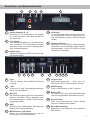
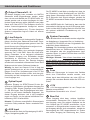
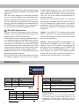
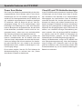
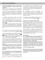
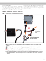
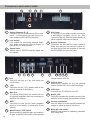
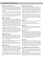
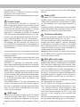
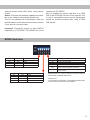
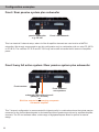
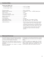
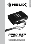
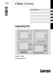
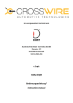
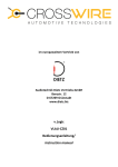
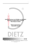
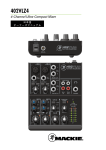
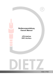
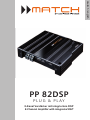
deutsch / english
PP 82DSP
P LU G & P L AY
8-Kanal Verstärker mit integriertem DSP
8-Channel Amplifier with integrated DSP
Herzlichen Glückwunsch!
Sehr geehrter Kunde,
wir gratulieren Ihnen zum Kauf dieses hochwertigen
MATCH Verstärkers mit integriertem DSP.
MATCH setzt mit der PP 82DSP neue Maßstäbe im
aufstrebenden Plug & Play Markt. Dabei profitieren
Sie als Kunde direkt von unserer nahezu 30 jährigen Erfahrung in der Forschung und Entwicklung
von Audiokomponenten.
Dieser Plug & Play Verstärker wurde von uns nach
neuesten technischen Erkenntnissen entwickelt
und zeichnet sich durch hervorragende Verarbeitung und eine überzeugende Anwendung ausgereifter Technologien aus.
Viel Freude an diesem Produkt wünscht Ihnen das
Team von
AUDIOTEC FISCHER
Allgemeine Hinweise
Allgemeines zum Einbau von MATCH-Komponenten
ten Sie bitte darauf, dass sich solche Teile auch in
der doppelten Wandverkleidung verbergen können.
Um alle Möglichkeiten des Produktes optimal ausschöpfen zu können, lesen Sie bitte sorgfältig die
nachfolgenden Installationshinweise. Wir garantieren, dass jedes Gerät vor Versand auf seinen einwandfreien Zustand überprüft wurde.
Allgemeines zum Anschluss des PP 82DSP Verstärkers
Vor Beginn der Installation unterbrechen Sie
den Minusanschluss der Autobatterie. Wir empfehlen Ihnen, die Installation von einem Einbauspezialisten vornehmen zu lassen, da der Nachweis
eines fachgerechten Einbaus und Anschlusses des
Gerätes Voraussetzung für die Garantieleistungen
sind.
Installieren Sie Ihren PP 82DSP Verstärker an einer
trockenen Stelle im Auto und vergewissern Sie sich,
dass der Verstärker am Montageort genügend Kühlung erhält. Montieren Sie das Gerät nicht in zu kleine, abgeschlossene Gehäuse ohne Luftzirkulation
oder in der Nähe von wärmeabstrahlenden Teilen
oder elektronischen Steuerungen des Fahrzeuges.
Im Sinne der Unfallsicherheit muss der Verstärker
professionell befestigt werden. Dieses geschieht
über Schrauben, die in eine Montagefläche eingeschraubt werden, die wiederum genügend Halt
bieten muss.
Bevor Sie die Schrauben im Montagefeld befestigen, vergewissern Sie sich, dass keine elektrischen
Kabel und Komponenten, hydraulische Bremsleitungen, der Benzintank etc. dahinter verborgen
sind. Diese könnten sonst beschädigt werden. Ach2
Der PP 82DSP Verstärker darf nur in Kraftfahrzeuge eingebaut werden, die den 12V-Minuspol
an Masse haben. Bei anderen Systemen kann der
MATCH PP 82DSP und die elektrische Anlage des
Kfz beschädigt werden.
Verwenden Sie zur Verbindung des MATCH PP
82DSP mit dem Autoradio ausschließlich das
beiliegende MATCH-Anschlusskabel! Die Verwendung eines anderen Kabels kann zu Schäden an ihrer Anlage führen. Die Sicherungen im
Verstärker dürfen nur mit den gleichen Werten
(2 x 25A) ersetzt werden, um eine Beschädigung
des Gerätes zu verhindern. Höhere Werte können zu gefährlichen Folgeschäden führen.
Die Kabelverbindungen müssen so verlegt sein,
dass keine Klemm-, Quetsch- oder Bruchgefahr
besteht. Bei scharfen Kanten (Blechdurchführungen) müssen alle Kabel gegen Durchscheuern
gepolstert sein. Ferner darf das Versorgungskabel
niemals mit Zuleitungen zu Vorrichtungen des Kfz
(Lüftermotoren, Brandkontrollmodulen, Benzinleitungen etc.) verlegt werden.
Anschluss- und Bedienelemente
1
2
3
4
1
Output Channels E - H
Anschluss für die Lautsprecher der Kanäle
E - H oder alternativ einen passiven MATCH
PP Subwoofer.
2
Line Output
Vorverstärkerausgänge zum Anschluss weiterer Verstärker. Zur Einschaltung weiterer
Verstärker muss der Remote Ausgang (Rem
Out) verwendet werden.
3
Optical Input
Optischer Eingang im SPDIF-Format für digitale Stereosignale
6
7
8
9
10
5
4
AUX Input
3,5 mm Klinkenbuchse zum Anschluss externer Signalquellen. Dieser Eingang kann sowohl automatisch als auch manuell aktiviert
werden.
5
System Connector
Anschluss für das MATCH Anschlusskabel.
Verwenden Sie ausschließlich das OriginalAnschlusskabel, um die PP 82DSP mit dem
Autoradio zu verbinden.
11
12 13 14 15
6
Fuse
LED zur Anzeige einer defekten Sicherung
im Gerät.
11
Control Input
Multifunktionsanschluss - dient zum Anschluss der URC 2A und weiterem Zubehör
7
+12V
Anschluss für das Versorgungsspannungskabel +12V der Batterie.
12
USB Eingang
Dient zum Anschluss an den Computer.
8
Rem Out
Der Remote Ausgang dient zum Einschalten
weiterer Verstärker. Dieser Ausgang muss
bei Verwendung der LineOut Cinch-Ausgänge genutzt werden
13
Status LED
Die Status LED zeigt den Betriebszustand
und den ausgewählten Speicherbereich an.
14
Control Taster
Dient zum Umschalten der Sound Setups
oder zum Resetten des Gerätes
15
MicroSD Kartenleser
Kartenleser zum Aufspielen von kompletten
DSP-Setups
9
GND
Anschluss des Massekabels (Minuspol der
Batterie oder Fahrzeugchassis.
10
MODE Switch / DIP Switch
Dienen zur Lautstärkeanpassung und zur
Konfiguration der Fernbedienung
3
Inbetriebnahme und Funktionen
1 Output Channels E - H
An diesen Ausgang kann entweder ein MATCH
Subwoofer direkt angeschlossen werden, wobei
dann vier der acht Kanäle der PP 82DSP dafür verwendet werden und an allen Ausgängen ein identisches Signal anliegen sollte. Alternativ kann jeder
Kanal auch über die PC-Tool Software einzeln für
andere Anwendungszwecke konfiguriert werden
(z.B. als Center-Speaker etc.). Für den Anschluss
anderer Lautsprecher liegt ein Kabel mit offenen
Enden bei.
2 Line Outputs
Die Line Outputs G und H sind spezielle Signalausgänge, die durch den „Balanced Dual Audio Transformer“ von der Eingangsmasse getrennt sind. Dadurch können keine Störgeräusche aufgrund von
Masseverschleifungen auftreten.
Diese Ausgänge liefern eine maximale Ausgangsspannung von 3 Volt RMS. Wenn Sie diese Ausgänge verwenden, ist es zwingend erforderlich,
den Remote Ausgang zum Einschalten des/der
Verstärker/s zu verwenden, da ansonsten Störsignale auftreten können. Der Remote Ausgang
schaltet sich automatisch während des Power Save
Modus sowie bei einem Software-Update ab.
Wichtig: An den Line Outputs G und H liegt das
gleiche Audiosignal wie an den Lautsprecherausgängen G und H an. Veränderungen in der PC-Tool
Software an diesen Kanälen wirken sich also gleichermaßen auf die Lautsprecher- wie auch auf die
Line-Ausgänge aus.
3 Optical Input
Optischer Eingang im SPDIF-Format für den Anschluss an Signalquellen mit digitalem Ausgang.Die
„Sampling Rate“ dieses Eingangs muss zwischen
6 - 192 kHz liegen. Das Eingangssignal wird automatisch an die interne Abtastrate angepasst. Um
diesen Eingang aktivieren und in der Lautstärke
regeln zu können, ist die optional erhältliche Fernbedienung URC 2A erforderlich.
Hinweis: Es können ausschließlich Stereosignale
und keine Dolby-codierten Daten verarbeitet werden!
4 AUX Input
Dieser Anschluss dient als Signaleingang für MP3Player, Navigationsgeräte, etc.
4
Die PP 82DSP ist ab Werk so konfiguriert, dass sie
bei Erkennung eines Musiksignals am AUX-Eingang diesen automatisch aktiviert. Sollte für mehr
als 2 Sekunden kein Signal anliegen, schaltet die
PP 82DSP automatisch wieder auf das Radiosignal
um.
Wenn MODE Switch Nr. 5 aktiviert ist, dann wird die
automatische Aktivierung des AUX Eingangs deaktiviert und der AUX Eingang lässt sich manuell über
die optional erhältliche Fernbedienung ein- und
ausschalten.
5 System Connector
Diese Buchse dient zum Anschluss des mitgelieferten Kabelbaums. Verwenden Sie zur Verbindung
der MATCH PP 82DSP mit dem Originalradio ausschließlich diesen Kabelbaum.
Achtung: Die Verwendung anderer oder ähnlicher
Kabelbäume kann zur Zerstörung des Verstärkers,
des Autoradios oder der angeschlossenen Lautsprecher führen. In jedem Fall führt dies zum Erlöschen der Garantie.
Wichtiger Hinweis: Über diesen Anschluss wird
die PP 82DSP nicht mit Spannung versorgt. Es ist
daher zwingend erforderlich, dafür die nachfolgend
mit (7) und (9) gekennzeichneten Klemmen zu verwenden.
6 Fuse
Sollten die Sicherungen im Inneren des Gerätes
durch eine Fehlfunktion zerstört werden, wird
dieses durch das Aufleuchten der roten LED angezeigt. Bei normalem Betrieb bleibt die LED erloschen.
7 +12V
Das +12V-Versorgungskabel ist am Pluspol der
Batterie anzuschließen.
Empfohlener Querschnitt: min. 10 mm².
8 Rem Out
Dieser Ausgang dient dazu, weitere Verstärker
einzuschalten. Verwenden Sie in jedem Fall diesen Ausgang, wenn Sie weitere Verstärker an die
Line Outputs der PP 82DSP anschließen, da es
ansonsten zu Störgeräuschen kommen kann. Dieser Ausgang aktiviert sich automatisch, sobald der
Bootvorgang des DSP abgeschlossen ist. Zudem
wird dieser Ausgang bei Aktivierung des „Power
Save Modes“ und bei Betriebssoftware-Updates
abgeschaltet.
9 GND
Das Massekabel sollte am zentralen Massepunkt
(dieser befindet sich dort wo der Minuspol der Batterie zum Metallchassis des Kfz geerdet ist) oder an
einer blanken, von Lackresten befreiten Stelle des
Kfz-Chassis angeschlossen werden.
10 MODE Switches / DIP Schalter
Die sechs einzelnen MODE Switches dienen zur
Anpassung der Lautstärke und zur Konfiguration
der Fernbedienung, wenn deren Funktion nicht
über die PC-Tool Software definiert wird.
MODE Switch 1 und 2 dienen zur Lautstärkeanpassung aller acht Ausgangskanäle!
MODE Switch 3 und 4 dienen zur Lautstärkeanpassung aller Kanäle, die als Subwooferausgang definiert wurden.
MODE Switch 5 legt die Funktion des Mode Schalters auf der Fernbedienung fest.
MODE Switch 6 aktiviert die Funktionen der Fernbedienung.
11 Control Input
Dieser Multifunktionsanschluss dient zum Anschluss von MATCH Zubehörprodukten, wie beispielsweise der Fernbedienung MATCH URC 2A.
Mit Hilfe dieser Fernbedienung können diverse
Funktionen des DSP-Verstärkers gesteuert werden.
Die Fernbedienung besitzt zwei Regler und einen
Schalter, dessen Funktionalität sich in der PC-Tool
Software frei konfigurieren lässt.
Nach dem Anschließen der Fernbedienung an die
PP 82DSP muss der MODE Switch Nr. 6 oder in
der PC-Tool Software die Fernbedienung im Device
Configuration Menü aktiviert werden.
Hinweis: Wenn die Fernbedienung in der PC-Tool
Software aktiviert wird, dann werden automatisch
die MODE Switch Schalter Nr. 5 und Nr. 6 am Gerät
deaktiviert. Diese werden erst wieder aktiviert,
wenn die Option im PC-Tool wieder abgeschaltet
wird. Sofern im PC-Tool die Fernbedienungseigenschaften nicht anderweitig definiert wurde, ergeben
sich folgende Funktionen:
CONTROL I: Einstellen der Lautstärke des AUX
Eingangs - die Lautstärke muss nicht mehr direkt
an der Signalquelle eingestellt werden.
CONTROL II: Einstellen der Subwoofer Lautstärke.
Jeder Ausgang, der in der PC-Software als Subwooferausgang definiert worden ist, kann darüber
in der Lautstärke verändert werden.
MODE Schalter: Deaktivierung der Klangverbesserungseigenschaften des internen DSPs zu Vorführzwecken. Mit Hilfe dieser Funktion kann man
schnell und einfach zwischen dem Original-Sound
ohne jegliche DSP-Beeinflussung und dem von Ihnen erstellten Setup hin- und herschalten. Bei gedrücktem Schalter ist der DSP abgeschaltet und die
Kanäle E - H deaktiviert.
Wenn der MODE Switch Nr. 5 am Gerät aktiviert
wird, ändert sich die Funktionalität des Schalters
auf der Fernbedienung dahingehend, dass dieser
zur manuellen Steuerung des AUX-Eingangs genutzt werden kann. Bei gedrücktem Schalter ist der
AUX Eingang aktiv.
12 USB Eingang
Mit Hilfe dieses Eingangs wird die PP 82DSP über
das beiliegende Kabel mit dem Computer verbunden und kann anschließend über das PC-Tool konfiguriert werden.
Hinweis: Es können keine USB Speichermedien
angeschlossen werden.
13 Status LED
Die Status LED zeigt den Betriebszustand des Verstärkers an. Leuchtet die LED grün, so ist der erste
Speicherplatz (af1) im DSP geladen. Leuchtet die
LED orange, so ist der zweite Speicherbereich (af2)
geladen. Sofern die LED rot leuchtet, ist die Sicherheitsschaltung für Unterspannung aktiv.
Sollte die LED rot blinken, so ist der interne Speicher des DSP leer. Sofern letzteres der Fall ist,
muss über die PC-Tool Software oder über den
MicroSD Kartenleser ein neues DSP Setup eingespielt werden.
14 Control Taster
Mit Hilfe des Control Tasters lässt sich zwischen
den Speicherbereichen eins und zwei umschalten.
Sound Setups, die die Dateiendung „af1“ haben,
werden automatisch in den ersten Speicherbereich
geschrieben, Sound Setups mit der Dateiendung
„af2“ werden automatisch in den zweiten Speicherbereich geschrieben. Zum manuellen Umschalten
der zwei Setups muss der Control Taster eine Se5
kunde lang gedrückt werden. Der Umschaltvorgang
wird durch einmaliges rotes Blinken der Status LED
angezeigt.
Wird der Taster länger als 5 Sekunden gedrückt,
so wird das Gerät resettet und der gesamte interne
Speicher gelöscht! Anschließend wird dies durch
ein rotes Dauerblinken der Status LED angezeigt.
Achtung: Nach dem Resetten des Gerätes kann die
PP 82DSP keine Audiosignale mehr wiedergeben,
bis ein neues Sound Setup eingespielt wurde.
15 MicroSD Kartenleser
Über den MicroSD Kartenleser können SoftwareUpdates sowie komplette DSP-Setup-Dateien eingespielt werden, die alle Einstellungen
für den DSP beinhalten. Nachdem die MicroSD Karte eingesteckt wurde, wird die Setup-Datei automatisch in die PP 82DSP kopiert. Der Kopiervorgang
wird durch ein rotes Blinken der Status-LED angezeigt und ist beendet, wenn diese wieder grün bzw.
orange leuchtet. Nachdem die Datei kopiert wurde,
muss die MicroSD Karte wieder entfernt werden.
Achtung: Entfernen Sie die MicroSD Karte nicht
während des Kopiervorgangs!
Die PP 82DSP kann zwei verschiedene Sound Setup Dateien verwalten. Zum einen Sound Setups
mit der Dateiendung „af1 / ac1“, die in den ersten
Speicherbereich geschrieben werden und zum anderen Sound Setup Dateien mit der Dateiendung
„af2 / ac2“, die in den zweiten Speicherbereich geschrieben werden.
Mit Hilfe des Control-Tasters kann man zwischen
den Setups umschalten. Alternativ kann man in der
PC-Tool Software den „Mode Switch“ der optional
erhältlichen Kabelfernbedienung so konfigurieren,
dass damit ebenfalls ein Umschalten der Setups
möglich ist.
Hinweis: Das DSP PC-Tool installiert beim ersten
Öffnen automatisch die neueste Betriebssoftware
auf dem Speicherplatz 1 sofern noch nicht die aktuelle Version installiert ist.
Wichtig: Fahrzeugspezifische Setup-Dateien anderer MATCH Verstärker (z.B. PP 50DSP / PP
52DSP) sind in der PP 82DSP nicht spielfähig! Es
gibt jedoch für die afp-Dateien der PP 50DSP und
PP 52DSP einen Kompatibilitätsmodus, so dass
diese Dateien über das PC-Tool geladen werden
können. Es wird jedoch dringend empfohlen anschließend die Einstellungen zu kontrollieren.
MODE Switches
Switch Nr. 1 Switch Nr. 2
OFF
OFF
ON
OFF
OFF
ON
ON
ON
Lautstärkeanpassung
0 dB
- 4 dB
+ 2 dB
- 2 dB
Diese Lautstärkeanpassung wirkt sich auf alle 8
Ausgangskanäle aus!
Switch Nr. 3 Switch Nr. 4
OFF
OFF
ON
OFF
OFF
ON
ON
ON
6
Lautstärkeanpassung
0 dB
- 4 dB
+ 2 dB
- 2 dB
Diese Lautstärkeanpassung wirkt sich auf alle
Subwooferkanäle aus!
Switch Nr. 6 Fernbedienung URC 2A
OFF
Fernbedienung deaktiviert
ON
Fernbedienung aktiviert
Switch Nr. 5 Mode Schalter URC 2A
Mode Schalter der Fernbedienung schaltet zwiOFF
schen Original und MATCH Soundupgrade hin
und her
Mode Schalter der Fernbedienung schaltet zwiON
schen Radiosignal und AUX Eingang um.
MODE Switch Nr. 5 hat nur bei aktivierter Fernbedienung eine Funktion.
Hinweis: Wenn in der PC-Tool Software die Fernbedienung aktiviert wurde, werden MODE Switch Nr. 5 und
6 deaktiviert. Um diese wieder zu aktivieren, muss die
Fernbedienung in der Software wieder deaktiviert werden.
Spezielle Features der PP 82DSP
Power Save Modus
Der Power Save Modus ist standardmäßig in allen fahrzeugspezifischen Sound Setups sowie in den Grundeinstellungen der PC-Tool Software implementiert. Er
erlaubt es, die Leistungsaufnahme der PP 82DSP (und
ggf. zusätzlich angeschlossener Verstärker) drastisch
zu reduzieren, wenn für länger als 60 sec. kein Eingangssignal anliegt. Es ist zu berücksichtigen, dass
heutzutage viele Fahrzeuge mit „CAN“ oder ähnlichen
internen Bussystemen ausgestattet sind, die das Radio
für den Anwender „unsichtbar“ noch bis zu 45 min. eingeschaltet lassen, selbst wenn man zwischenzeitlich
das Fahrzeug verlassen und abgeschlossen hat.
Sobald der „Power Save Mode“ aktiv ist, werden die
internen Verstärkerstufen der PP 82DSP sowie der
„Remote Output“ abgeschaltet und damit die Stromaufnahme auf weniger als 250 mA reduziert. Der Verstärker geht innerhalb von 2 sec. wieder in den normalen
Betriebszustand über, sobald ein Musiksignal an seinem Eingang anliegt.
Es ist zudem möglich, über die PC-Tool Software die
Abschaltverzögerung zu variieren bzw. den „Power
Save Mode“ komplett zu deaktivieren.
Class HD und P³S-Netzteiltechnologie
In der PP 82DSP werden erstmals die Vorteile der Class
H-Technologie mit dem Prinzip eines Class D Verstärkers kombiniert. Das Resultat ist ein unübertroffener
Wirkungsgrad, der herkömmliche Class D-Verstärker
nochmals übertrifft. Die Vorteile spielt das Class HDKonzept bei kleiner und mittlerer Aussteuerung aus,
da das neuartige P³S-Netzteil die interne Versorgungsspannung der Leistungsstufen in Abhängigkeit von der
Amplitude des Eingangssignals regelt. Damit wird die
mittlere, vom Verstärker erzeugte Verlustleistung drastisch reduziert. Wie alle anderen MATCH-Verstärker
ist natürlich auch die PP 82DSP für Fahrzeuge mit
Start-/Stop-Funktion geeignet, da das P³S-Netzteil
Schwankungen der Bordnetzspannung ausgleicht.
Wichtig: Nichtsdestotrotz verfügt die PP 82DSP über
eine Unterspannungserkennung. Wenn die Bordspannung für länger als 5 Sekunden unter 9,6 Volt fällt,
geht der Verstärker in den „Protect Mode“ (Status LED
leuchtet dauerhaft rot), um eine weitere Entladung der
Batterie zu verhindern.
7
Einbau und Installation
Der MATCH PP 82DSP Verstärker wird wie nachfolgend beschrieben an das Autoradio angeschlossen.
Achtung: Für die Durchführung der nachfolgenden
Schritte werden Spezialwerkzeuge und Fachwissen benötigt. Um Anschlussfehler und Beschädigungen zu vermeiden, fragen Sie im Zweifelsfall
Ihren Fachhändler und beachten Sie zwingend die
allgemeinen Anschluss- und Einbauhinweise (siehe
Seite 2).
einer Hauptsicherung (50 A) abgesichert werden.
Verwenden Sie bei kurzen Leitungen (< 1m) einen
Querschnitt von mindestens 6 mm². Bei längeren
Leitungen empfehlen wir einen Querschnitt von 10
mm² bis 16mm².
Das Massekabel (gleicher Querschnitt wie
das +12V-Kabel) muss an einem blanken, von
Lackresten befreiten Massepunkt des Kfz-Chassis
oder direkt an dem Minuspol der Autobatterie angeschlossen werden.
1. Nachdem das Radio mit Hilfe der entsprechenden Werkzeuge ausgebaut ist, trennen Sie
den Fahrzeugkabelbaum vom Autoradio. Verbinden Sie den Fahrzeugkabelbaum anschließend mit
der Kupplung des MATCH-Anschlusskabels, siehe
Abb. 3 1 .
Je nach Fahrzeugtyp benötigen Sie hierfür gegebenenfalls einen fahrzeugspezifischen ISO-Adapter.
Eine Liste aller Fahrzeuge und der eventuell benötigten Adapter finden Sie auf www.audiotec-fischer.
com.
4. Verbinden Sie das MATCH-Anschlusskabel mit
der MATCH PP 82DSP, siehe Abb. 3 3 .
2. Verbinden Sie die Stecker des MATCH-Anschlusskabels mit dem Autoradio, siehe Abb. 3 2 .
3. Die Stromversorgung der PP 82DSP erfolgt niemals über das MATCH-Anschlusskabel, sondern
ausschließlich über die dafür vorhandenen massiven Schraubklemmen sowie ein separates Stromversorgungskabel direkt zur Batterie.
Nutzen Sie niemals die Spannungsversorgung direkt vom Radio. Die PP 82DSP hat zwar einen geringen durchschnittlichen Strombedarf, kann aber
bedingt durch die dynamische Netzteilregelung für
Sekundenbruchteile sehr hohe Ströme (bis zu 50A)
ziehen.
Wichtig: Beim direkten Anschluss der PP 82DSP
an die Spannungsversorgung des Radios riskieren Sie massive Schäden an der Bordnetzelektrik Ihres Fahrzeuges bis hin zu einem Kabelbrand!
Vor dem Anschluss des +12V-Versorgungskabels an das Bordnetz muss die Autobatterie abgeklemmt werden.
Das +12V-Stromkabel ist am Pluspol der Batterie anzuschließen. Die Plusleitung sollte in einem
Abstand von max. 30 cm von der Batterie mit
8
Optimierung der Lautstärkeeinstellung:
Schalten Sie das Radio ein und drehen Sie die
Lautstärke langsam auf. Sobald Sie ein Verzerren
der Lautsprecher wahrnehmen, sind Sie bei der
maximalen Lautstärke angekommen. Um den Regelbereich zu vergrößern, können Sie mit Hilfe der
MODE Switches Nr. 1 und 2 die Ausgangslautstärke der PP 82DSP verringern (siehe Seite 6). Sofern
ihr Autoradio bis zur maximalen Lautstärke aufgedreht ist und es zu keinem Verzerren kommt, können Sie mit Hilfe der MODE Switches Nr. 1 und 2
die Ausgangslautstärke erhöhen. Nutzen Sie diese
Funktion jedoch nur mit Vorsicht.
Warnhinweis:
Der PP 82DSP-Verstärker hat eine deutlich höhere Leistung als das Original-Autoradio. Viele
werksseitigen Lautsprecher können die zusätzliche Leistung evtl. nicht dauerhaft verkraften.
Soweit Sie nicht die vorhandenen
Lautsprecher gegen leistungsfähigere Ausführungen tauschen sollten, seien Sie bitte sehr
vorsichtig mit der Einstellung der Lautstärke. Zu hohe Lautstärken, die die Lautsprecher
schädigen können, machen sich durch einen
verzerrten Klang bemerkbar.
Wichtig: Audiotec Fischer übernimmt keinerlei
Garantie für das Zusammenspiel der PP 82DSP
in Verbindung mit werksseitig verbauten Lautsprechern!
Hinweis: MOST-Bus
Bei einigen Fahrzeugen kann es notwendig
sein, die Lichtleiterverbindung aus dem Original-Radioanschlussstecker auszulösen und
stattdessen in den Radio-Stecker eines ISOAdapters einzustecken. Hierfür ist extra eine
Aussparung im ISO-Adapter vorhanden. Dies
ist zwingend bei allen Fahrzeugen notwendig,
die einen Lichtleiteranschluss im Originalradiokabelbaum haben.
Abb. 3 Anschluss des Verstärkers an das Autoradio
4
3
5
Kupplung für
Originalkabelbaum
2
1
Kupplung und Stecker
für Originalkabelbaum
oder ISO-Adapter
1 ISO-Kupplung - hier wird der Kabelbaum des Originalradios oder ein ISO-Adapter einge-
steckt.
2 ISO-Stecker - Diese werden in das Originalradio oder in den ISO-Adapter eingesteckt.
3 Dieser 20-polige Stecker wird in den MATCH PP 82DSP Verstärker eingesteckt.
4 Optional: ISO-Adapter - sollten die ISO-Stecker des mitgelieferten Kabelbaums nicht zum
Originalradio passen, muss ein ISO-Adapter verwendet werden.
5 Der Stromanschluss der PP 82DSP wird mit Hilfe eines geeigneten Kabels direkt an die Bat-
terie angeschlossen - die Plus-Leitung muss kurz vor der Batterie noch einmal abgesichert
werden
9
Anschluss an den Computer
Die PP 82DSP kann mit Hilfe der DSP PC-Tool Software frei konfiguriert werden. Die Software stellt
alle Funktionen übersichtlich und bedienerfreundlich zur Verfügung, so dass Sie diese individuell einstellen können. Dabei können alle acht DSP Kanäle
separat eingestellt werden.
Bevor Sie den Verstärker das erste Mal an einen
Computer anschließen, gehen Sie auf unsere
Homepage und laden Sie sich die aktuelle Software
Version herunter. Es wird dringend empfohlen, regelmäßig nach Updates der Software zu schauen,
damit das Gerät immer auf dem aktuellsten Stand
ist.
Die Software sowie die dazu gehörige Bedienungsanleitung finden Sie auf www.audiotec-fischer.com.
Es wird dringend empfohlen, die Bedienungsanleitung der Software vor der ersten Benutzung durchzulesen, um Komplikationen und Fehler zu vermeiden.
Stellen Sie vor der Installation der Software sicher,
dass das Gerät nicht an den Computer angeschlos-
sen ist. Schließen Sie das Gerät erst nach der Installation an.
Um die Software zu installieren, müssen folgende
Schritte durchgeführt werden:
1. Laden Sie die DSP PC-Tool Software unter
www.audiotec-fischer.com herunter.
2. Installieren Sie die Software auf ihrem Computer. Während der Installation wird automatisch
auch der USB-Treiber für das Gerät installiert.
3. Nach der Installation können Sie den Verstärker
mit dem beiliegenden USB-Kabel an den Computer anschließen.
4. Schalten Sie den Verstärker ein und starten Sie
die Software. Wenn die Betriebssoftware des
Verstärkers nicht mehr aktuell ist, wird diese automatisch in dem angewählten Speicherbereich
1 aktualisiert.
5. Sie können nun den internen DSP des Verstärkers mit der PC-Tool Software frei konfigurieren.
ATF DSP PC-Tool
erweiterte
Einstellungen
Kanalkonfiguration
Hochpassfilter
Tiefpassfilter
Frequenzgraph
Equalizer
10
Kanalanwahl
Laufzeitkorrektur
Ausgangspegel
EQ Feineinstellung
Konfigurationsbeispiele
Front / Rear plus Subwoofer
passiver Subwoofer
bspw. PP 10E
Front / Rear Kanäle
Dies ist ein klassisches 5-Kanal-Setup, bei dem vier der acht Verstärkerkanäle dazu genutzt werden,
einen MATCH-Subwoofer anzusteuern. Wir empfehlen diese Kombination nur in Verbindung mit unseren
Subwoofern PP 8E-Q oder PP 10E-D.
Front 2-Wege Vollaktiv / Rear passiv plus Subwoofer
Front Hochtöner
Front Tieftöner /
Rear Kanäle
Subwoofer mit Doppelschwingspule
(optimal 2 x 2 Ohm)
oder
Cinch-Ausgang zum Anschluss eines
separaten Subwoofer Verstärkers
Diese 7-Kanal-Konfiguration ist für höchste Qualitätsansprüche empfehlenswert, bei der die typischen
passiven Frequenzweichen für die vorderen Tieftöner/Hochtöner entfallen und jeder Lautsprecher von
einem einzelnen Verstärkerkanal angesteuert wird.
Die PC Tool Software bietet mit ihren verschiedenen Varianten an Hoch- und Tiefpassfiltern die Möglichkeit, sehr präzise eine passende aktive Frequenzweiche zu definieren.
11
Technische Daten
Ausgangsleistung RMS / Max:
• Alle Kanäle an 4 Ohm: ................................................8 x 55 / 110 Watt
• Alle Kanäle an 2 Ohm: ................................................8 x 70 / 140 Watt
Frequenzbereich..............................................................20 Hz - 22.000 Hz
Anzahl der Eingänge........................................................4 x Highlevel, 1 x Aux, 1 x SPDIF (optisch)
DSP Auflösung.................................................................56 Bit
DSP Rechenleistung .......................................................172 MIPS
Klirrfaktor (THD)...............................................................< 0,03%
Signal-/Rauschabstand....................................................> 103 dB
Dämpfungsfaktor..............................................................> 50
Eingangsimpedanz...........................................................30 Ohm
Unterspannungserkennung:.............................................9,6 Volt (max. 5 Sek. bis hinab zu 6 Volt)
Abmessungen (H x B x T)................................................44 x 185 x 164 mm
zusätzliche Features�������������������������������������������������������Class HD-Technologie mit dynamisch geregeltem
Netzteil, Start-Stop-Fähigkeit, interner 56 Bit
DSP, interner Speicher für 2 Sound Setups, USB
Anschluss, AUX-Eingang, optischer Eingang,
Fernbedienungseingang, 2 galvanisch getrennte
LineOuts
Garantiehinweis
Die Garantieleistung entspricht der gesetzlichen
Regelung. Von der Garantieleistung ausgeschlossen sind Defekte und Schäden, die durch Überlastung oder unsachgemäße Behandlung entstanden
sind. Eine Rücksendung kann nur nach vorheriger
Absprache in der Originalverpackung, einer detaillierten Fehlerbeschreibung und einem gültigen
Kaufbeleg erfolgen.
12
Technische Änderungen und Irrtümer vorbehalten!
Für Schäden am Fahrzeug oder Gerätedefekte,
hervorgerufen
durch
Bedienungsfehler
des
Gerätes, können wir keine Haftung übernehmen.
Alle MATCH Verstärker sind sowohl mit einer
E-Kennzeichnung als auch einer CE-Kennzeichnung versehen. Damit sind die Geräte für den Betrieb in Fahrzeugen innerhalb der Europäischen
Union (EU) zertifiziert.
Congratulations!
Dear Customer,
Congratulations on your purchase of this high-quality MATCH product.
With the PP 82DSP, MATCH is setting new standards in the evolving plug & play market.
We wish you many hours of enjoyment with your
new MATCH PP 82DSP.
Yours,
AUDIOTEC FISCHER
General instructions
General installation instructions for MATCH
components
General instruction for connecting the PP
82DSP amplifier
To prevent damage to the unit and possible injury,
read this manual carefully and follow all installation instructions. This product has been checked for
proper function prior to shipping and is guaranteed
against manufacturing defects.
The PP 82DSP may only be installed in vehicles
which have a negative ground electrical system.
Any other system may cause damage to the
amplifier and the electrical system of the vehicle.
Before starting your installation, disconnect
the battery’s negative terminal to prevent
damage to the unit, fire and/or risk of injury. For
a proper performance and to ensure full warranty
coverage, we strongly recommend to get this product installed by an authorized MATCH dealer.
Install your PP 82DSP in a dry location with sufficient air circulation for proper cooling of the
equipment. The amplifier should be secured to
a solid mounting surface using proper mounting
hardware. Before mounting, carefully examine the
area around and behind the proposed installation location to insure that there are no electrical
cables or components, hydraulic brake lines or any
part of the fuel tank located behind the mounting
surface. Failure to do so may result in unpredictable
damage to these components and possible costly
repairs to the vehicle.
Use only the provided MATCH cable for connection of the PP 82DSP. The use of other
cables can result in damage of the amplifier, the head unit / radio or the connected
loudspeakers!
Prior to installation, plan the wire routing to
avoid any possible damage to the wire harness.
All cabling should be protected against possible
crushing or pinching hazards. Also avoid routing
cables close to potential noise sources such as
electric motors, high power accessories and other
vehicle harnesses.
The fuse may only be replaced by an
identically rated fuse (2 x 25 A) to avoid damage
of the amplifier.
13
Connectors and control units
1
3
4
1
Output Channels E - H
Connector for the loudspeakers of the channels E – H. Alternatively you can directly connect a passive MATCH PP subwoofer.
2
Line Output
Line outputs for connecting external amplifiers. Make sure that the „Remote Output” is
used to turn on these devices.
3
6
7
5
4
AUX Input
3,5 mm jack for an external audio source like
a MP3-player, navigation device, etc.. This
input can either be activated automatically or
via an optional cable remote control.
5
System Connector
Connector for the MATCH cable harness.
Make sure that you only use the original cable that comes with the amplifier to connect
the PP 82DSP with your car radio.
Optical Input
Optical input in SPDIF format for digital stereo signals
6
14
2
7
8
9
10
11
12 13 14 15
remote control URC 2A.
Fuse
This LED will light up if the fuse inside the
unit is blown.
11
+12V
Connector for the +12 V power cable to the
positive terminal of the battery.
Control Input
Multifunction interface for e.g. the optional
remote control URC 2A or other accessory.
12
USB Input
Connects the PP 82DSP to your PC.
13
Status LED
This LED indicates the operating mode of the
amplifier and the setup that has been chosen
14
Control pushbutton
Use this button to either switch between the
setups or initiate a reset of the device.
15
MicroSD card reader
MicroSD card reader for uploading complete
DSP setup files.
8
Rem Out
The remote output has to be used to turn on/
off external amplifiers that are connected to
the RCA line outputs.
9
GND
Connector for the ground cable (negative
terminal of the battery or metal body of the
vehicle).
10
MODE Switch / DIP Switch
Allows modifying amplifier gain and subwoofer gain as well as functionality of the optional
Initial start-up and functions
1 Output channels E - H
You can directly connect a MATCH subwoofer to
this output, by using four of the eight amplifier channels of the PP 82DSP. Please make sure that in this
case the output signal of all these four channels is
identical.
Alternatively you can configure each channel individually for other purposes via the PC tool software
(e.g. center speaker or fully active configurations).
For the latter case a connector with flying leads is
included in delivery of the PP 82DSP.
2 Line Output
The two Line Outputs A and B are floating-ground
low-level outputs (max 3 Vrms) for connecting additional power amplifiers. Specially designed „Balanced Dual Audio Transformers” avoid any groundloops that may cause undesired alternator noise.
Please make sure that you always turn on/off external amplifiers using the “Remote Output” of the PP
82DSP. Never directly control the external amps by
a signal from the ignition switch of your car!
Important: The outputs G and H deliver the same
audio signal as the speaker outputs G and H. Any
changes in the setup via the PC-Tool software will
always have the same effect on the speaker outputs
and line outputs of the channels G and H!
3 Optical Input
Optical input in SPDIF format for connection to signal sources with a digital audio output. The sampling rate of this input must be between 6 and 192
kHz. The input signal is automatically adjusted to
the internal sample rate.
In order to activate this input the optional cable remote control URC 2A is necessary.
Notice: This amplifier can only handle stereo input
signals and no Dolby-coded digital audio stream.
4 AUX Input
This input automatically detects signals of external
devices like MP3-players, navigation devices, etc.
and switches to “AUX mode”. If there is no signal for
more than 2 seconds on the AUX input, the amplifier
automatically switches back to the radio signal.
If the MODE switch no. 5 is set to “on” position, the
automatic input detection will be deactivated. In this
case it is possible to manually switch to AUX input
using the optionally available remote control URC
2A.
5 System Connector
Please use this terminal only in combination with
the cable harness that is included in the delivery of
the amplifier. Never ever use any other harnesses
to connect the MATCH PP 82DSP to your car radio.
Caution: The use of other harnesses than the one
that is supplied with the amplifier may cause severe
harm to the amplifier, your car radio and your loudspeakers. In any case the warranty will be void!
Important: This connector does not allow connecting the amplifier to the car’s battery. It is mandatory
to use the terminals (7) and (9) which are described
in the following.
6 Fuse
If a severe malfunction inside the amplifier will blow
the internal fuses the LED lights up red.
During normal operation this LED will remain off.
7 +12V
Connect the +12 V power cable to the positive terminal of the battery. Recommended wire gauge: at
least AWG 8 or 10 mm².
8 Rem Out
We strongly recommend to use this output for turning on/off additional amplifiers that are connected
to the line outputs of the PP 82DSP. This is essential
to avoid any undesired pop noises during DSP boot
or software update process. Additionally this output
will be turned off when the “Power Save Mode” (see
page 17) of the amplifier is active.
9 GND
The ground cable should be connected to a common ground reference point (this is located where
the negative terminal of the battery is grounded
to the metal body of the vehicle), or to a prepared
metal location on the vehicle chassis, i.e. an area
which has been cleaned of all paint residues.
10 MODE Switches / DIP Switches
The six MODE switches allow adjusting the amplifier gain and the functionality of the optional remote
control when the PC-tool software is not used for
setting up the amplifier.
MODE switch nos. 1 and 2 are to adjust the overall
gain of all amplifier channels including line outputs.
MODE switch nos. 3 and 4 are to adjust the gain of
15
the subwoofer channels
MODE switch no. 5 defines the function of the toggle switch on the remote control
MODE switch no. 6 activates/deactivates the remote control.
11 Control Input
This multi-functional connector is designed for
MATCH accessory products like the cable remote
control URC 2A. With this remote it is possible to
control several features of the amplifier. It consists
of two rotary controls and one toggle switch.
Note that it is necessary to activate a connected
URC 2A either by setting MODE switch no.6 to “ON”
position or by the appropriate command in the Device Configuration Menu” of the PC tool software.
Notice: If you activate the remote control in the PC
tool software, the DIP switches no.5 and no.6 on
the PP 82DSP will automatically be disengaged. To
reactivate them you have to cancel this option in the
PC tool software.
As long as the functions of the remote control have
not been changed in the PC tool software these are
defined as follows:
CONTROL I: Adjusting the volume of the AUX input
– eliminates the need to adjust the volume on the
external source
CONTROL II: Adjusting the subwoofer volume.
Each output that has been defined as a subwoofer
channel in the PC tool software will then be affected
by this control.
MODE switch: Toggling between the original sound
system without any DSP processing and your optimized car specific DSP sound setup for demonstration purposes. The DSP and the output channels
E - H will be deactivated when the switch on the
remote is pressed.
If the MODE switch no. 5 is set to „ON” position, the
function of the switch on the URC 2A will change. In
this case it is possible to manually activate the AUX
input. The AUX input is activated when the switch
on the remote is pressed.
12 USB Input
Connect your personal computer to the PP 82DSP
using the provided USB cable. The required PC
software to configure this amplifier can be downloaded from the Audiotec Fischer website. Please
16
note: It is not possible to connect any USB storage
devices.
13 Status LED
The status LED indicates the operation mode of the
amplifier. Green means that setup 1 (af1) is loaded,
orange means that setup 2 (af2) is loaded. If it lights
up red constantly, the undervoltage protection is
active.
A flashing red light indicates that no setup is loaded.
In that case please load a new setup via the PC tool
software or the internal microSD card reader.
14 Control pushbutton
The control pushbutton allows the user to toggle
between two loaded setups „af1“ and „af2“.
To switch between the setups, the button has to be
pressed and held for approx. 1 second. Switching
is indicated by a singular red flash of the Status
LED. Pressing the button for 5 seconds completely
erases the internal memory. This is indicated by a
constant flashing of the Status LED.
Attention: After erasing the setups from memory
the PP 82DSP will not reproduce any audio output
until a new setup is loaded.
15 MicroSD card reader
The Micro SD card reader can be used to download
firmware and software updates as well as complete
DSP setup files containing all DSP settings. After
having inserted the MicroSD card into the card slot
of the PP 82DSP, the file will be automatically copied to the internal memory of the amplifier. While
the copy is in progress, the status LED flashes red.
It changes to green or orange once the process is
finished. Now the microSD card can be safely removed.
Attention: Never remove the MicroSD Card while
the copy process is in progress.
The PP 82DSP can manage two different setup
files. They are marked with the file extensions „.af1“
/ „ac1“ (stored in memory 1 of the amplifier) or „.af2“
/ „ac2“ (stored in memory 2 of the amplifier). Please
note: Do not store more than one “af1” or „ac1“ and
one “af2” or „ac2“ setup file on the microSD card
at a time.
With the control pushbutton you can toggle between
the two setups. Alternatively you can configure in
the PC tool software the mode switch function of the
optional remote control URC 2A as “setup switch”
as well.
Notice: Firmware and software updates are available on our website www.audiotec-fischer.com
The PC tool software will automatically install the
latest firmware on the last selected memory location
if your device is not up-to-date.
used for the PP 82DSP!
But it is possible to upload “.afp“-files of a PP50
DSP to the PP 82DSP via the PC tool software. This
is only a compatibility mode and all adjustments
should be checked carefully after using a PP50
DSP afp-file.
Important: Car-specific setups of other MATCH
amplifiers (e.g. PP 50DSP / PP 52DSP) can not be
MODE Switches
Switch no. 1
OFF
ON
OFF
ON
Switch no. 2
OFF
OFF
ON
ON
Amplifier overall gain
0 dB
- 4 dB
+ 2 dB
- 2 dB
Affects all eight output channels!
Switch no. 3 Switch no. 4
OFF
OFF
ON
OFF
OFF
ON
ON
ON
Subwoofer gain
0 dB
- 4 dB
+ 2 dB
- 2 dB
Only affects subwoofer channels!
Switch no. 6 remote control URC 2A
OFF
remote control deactivated
ON
remote control activated
Switch no. 5 Mode switch URC 2A
Mode switch on remote control bypasses
OFF
MATCH sound optimization if pressed
Mode switch on tremote control activates AUX
ON
input if pressed
MODE Switch no. 5 has no function if remote control is
deactivated via MODE switch no.6
Please note:
It is possible to deactivate / reactivate both Mode switches no.5 and 6 via the PC-tool software.
17
Unique Features of the PP 82DSP
Power Save Mode
The Power Save Mode is incorporated in the basic setup. It allows to significantly reduce the power
consumption of the PP 82DSP (or any additional
connected amplifier) once there’s no input signal for
more than 60 seconds. Please note that in many
up-to-date cars with “CAN” or any other internal bus
structures it may happen that the radio (and therefore the PP 82DSP as well) remains “invisibly” turned
on for up to 45 min. after leaving the car!
Once the “Power Save Mode is active the output
stages of the PP 82DSP and its “Remote Output”
will be turned off, thus reducing current draw to less
than 250 mA. The amp will turn again to full operation within 2 sec. if a music signal is applied.
It is possible to either modify the turn-off time of
60 sec. or completely deactivate the “Power Save
made” via the PC-tool
18
Class HD and P³S power supply technology
For the first time the PP 82DSP combines the advantages of a Class H technology with the principle
of a class D amplifier. The result is an unsurpassed
efficiency, which easily outperforms any conventional class D amplifier.
The new P³S power supply technology controls the
internal supply voltage for the output stages as a
function of the amplitude of the input signal. Thus
the average power dissipation of the amplifier is
dramatically reduced.
Like all other MATCH amplifiers the PP 82DSP is
perfectly prepared for cars with start-/stop feature.
Please note:
Nevertheless the PP 82DSP has an undervoltage
protection. If the supply voltage drops below 9.6
volts for more than 5 seconds the amplifier goes to
“Protect mode” (Status LED lights up red) in order
to avoid any further discharge of the car’s battery.
Installation
The MATCH PP 82DSP must be connected to
the head unit (radio) as follows:
Caution: Carrying out the following steps will
require special tools and technical knowledge. In
order to avoid connection mistakes and/or damage, ask your dealer for assistance if you have any
questions and follow all instructions in this manual
(see page 13).
1. After removing the radio from the dash using
appropriate tools, disconnect the vehicle harness
from the radio. Next, connect the vehicle harness
to the male connector of the MATCH cable harness,
see fig. 3 1
Depending on your car an additional car-specific
adaptor may be required.
A list of all cars and the respective adaptors can be
found on www.audiotec-fischer.com.
2. Connect the female connector of the MATCH
cable harness or the car-specific adaptor to the radio, see fig. 3 2 .
3. In case of the PP 82DSP the included MATCH
cable harness cannot and must not be used for the
power supply. Always directly connect the massive
screw terminals of this amplifier to your car’s battery
using appropriate wires (AWG 8 / 10 mm² or better).
Never use the power leads of the car radio itself!
Though the PP 82DSP only has a limited average
power consumption, it may draw very high currents
(up to 50A) for the fraction of a second due to its
dynamically controlled internal power supply.
Important: You may risk a severe damage of
your car radio and other electronic components
inside your vehicle or even a cable fire if you
use the car radio harness for the power supply
of the PP 82DSP!
Make sure to disconnect the battery before installing the PP 82DSP!
Connect the +12V power cable to the positive terminal of the battery. The positive wire from the battery
to the PP 82DSP power terminals needs to have
an inline fuse (50 A) at a distance of no more than
12 inches (30 cm) from the battery. If your power
wires are short (less than 1 m / 40”) then a wire gauge of 6 mm² / AWG 10 will be sufficient. In all other
cases we strongly recommend gauges of 10 - 16
mm² / AWG 6 – 8! The ground cable (same gauge
as the +12V wire) should be connected to a common ground reference point (this is located where
the negative terminal of the battery is grounded
to the metal body of the vehicle), or to a prepared
metal location on the vehicle chassis, i.e. an area
which has been cleaned of all paint residues.
4. Connect the MATCH harness to the MATCH PP
82DSP, see fig. 3 3 .
Optimizing the amplifier gain setting:
Turn on the car radio and the volume up gradually.
Maximum volume has been reached when loudspeaker distortion becomes audible. To increase
volume range of the radio use the MODE switches
nos. 1 and 2 (refer to page 17) to reduce the overall
gain of the PP 82DSP. If your radio is at maximum
volume without any distortion being audible, you
can use the MODE switches to increase the amplifier overall gain by +2 dB. Be careful when using
this function.
Caution:
The PP 82DSP amplifier has a significantly higher power output than the car radio itself. Most
of the OE speakers in the car will not be able to
handle this extra power permanently. As long as
you do not replace the original speakers by loudspeakers with higher power handling please
be very careful when you crank up the volume.
If you hear strong distortion, please reduce the
volume to an appropriate level in order to avoid
damaging your speakers.
Note: Audiotec Fischer is not responsible for
any damages to OE speakers that are used in
combination with the PP 82DSP!
Note - Cars equipped with MOST bus:
In cars equipped with MOST bus structure it is
mandatory to unplug the fiber-optic cable from
the original radio connector and insert it into the
radio connector of the MATCH cable harness,
which has a dedicated recess for this.
19
Abb. 3 Connection of the amplifier to the car radio
5
4
3
Female
connector for
original cable
harness
2
1
Male and female connector for original cable
harness or car-specific
adaptor
1 The ISO female connector will either be plugged into the vehicle harness that has been dis-
connected from the car radio or a car-specific adaptor.
2 The ISO male connector will either be plugged into the car radio or into a car-specific adaptor.
3 The 20-pole connector will be plugged into the MATCH PP 82DSP amplifier.
4 The power supply terminal has to be connected directly with the battery - use only adequate
cables and fuse the +12V wire close to the battery.
5 Optional: car-specific adaptor – such an adaptor may be required if the ISO connectors of
the provided PP 82DSP cable harness does not fit into your car radio.
20
Connection to a PC
It is possible to freely configure the PP 82DSP with
our DSP PC-tool software. The user interface is designed for easy handling of all functions and allows
to individually adjust all eight DSP channels.
Prior to connecting the amplifier to your PC, visit our
website and download the latest version of the PCtool software. Check from time to time for software
updates in order so that your amplifier is always upto-date.
You will find the software and the respective user
manual on www.audiotec-fischer.com.
We strongly recommend to carefully read the user
manual before using the software for the first time in
order to avoid any complications and failures.
Make sure that the amplifier is not connected to
your computer before the software and USB driver
is installed!
To install the software follow the next steps:
1. Download the PC-tool software from the website www.audiotec-fischer.com
2. Install the software on your computer. During
that process the required USB driver will be automatically installed as well.
3. After the software installation processed is
completed you can now connect the amplifier to
your PC using the provided USB cable.
4. Turn the amplifier on and then start the software. If the firmware of the amplifier is not the
latest version it will automatically be updated on
the currently selected memory position.
5. You are now ready to configure the PP 82DSP
according to your demands.
ATF DSP PC-Tool
Device
configuration
Channel
configuration
Highpass filter
Lowpass filter
Frequency
graph
Equalizer
Channel
selection
Time
alignment
Output
level
EQ fine
adjustment
21
Configuration examples
Front / Rear passive system plus subwoofer
passive subwoofer
e.g. PP 10E
Front / rear channels
This is a classical 5-channel setup, where 4 of the 8 amplifier channels are used to drive a MATCH
subwoofer. We strongly recommend to use this configuration only in combination with our subs PP 10E-D
or PP 8E-Q. The versions PP 7E-D and PP 7S-D may not be able to handle the full amount of amplifier
power.
Front 2-way full active system / Rear passive system plus subwoofer
Front tweeters
Front midbass /
rear speakers
subwoofer with dual voice-coil
(ideally 2 x 2 Ohms)
or
RCA line outputs for connecting a separate
subwoofer amplifier
This 7-channel configuration is recommended for highest quality in combination where the typical passive
crossover for the front midbass/tweeter is eliminated and those speakers are driven by separate amplifier
channels. The PC tool software offers a wide range of highpass/lowpass filters for precise crossover
design.
22
Technical Data
Output power RMS / max:
• All channels @ 4 Ohms: .............................................8 x 55 / 110 Watts
• All channels @ 2 Ohms: .............................................4 x 70 / 140 Watts
Frequency range..............................................................20 Hz - 22.000 Hz
Number of input channels................................................4 x highlevel, 1 x Aux, 1 x SPDIF optical input
DSP resolution..................................................................56 Bit
DSP processing power.....................................................172 MIPS
Total harmonic distortion (THD)........................................< 0,03%
Signal-to-noise ratio.........................................................> 103 dB
Damping factor.................................................................> 50
Input impedance...............................................................30 Ohms
Undervoltage detection....................................................9,6 Volts (max. 5 sec. down to 6 Volts)
Dimensions (H x W x D)...................................................44 x 185 x 164 mm / 1,73 x 7,28 x 6,46“
Additional features�����������������������������������������������������������HD technology with dynamically controlled power
supply, ready for start-/ stop, 56 bit digital signal
processing, internal memory for 2 different sound
setups, USB input, AUX input, optical input, input
for optional remote control, stereo line outputs
with balanced output transformers (floating
ground).
Warranty Disclaimer
The limited warranty comply with legal regulations.
Failures or damages caused by overload or improper use are not covered by the warranty.
Please return the defective product only with a
valid proof of purchase and a detailed malfunction
description.
Technical specifications are subject to change!
Errors are reserved!
For damages on the vehicle and the device, caused
by handling errors of the device, we can’t assume
liability.
All MATCH amplifiers are tagged with a E-Certification number and also a CE-Certification mark.
Thereby these devices are ceritified for a use
inside vehicles inside the European Union (EU).
23
Audiotec Fischer GmbH
Gewerbegebiet Lake II · Hünegräben 26 · D-57392 Schmallenberg
Tel.: +49 2972 9788 0 · Fax: +49 2972 9788 88
E-mail: [email protected] · Internet: www.audiotec-fischer.com