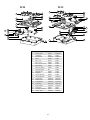
1
September 2003 INTRODUCTION The 2004 edition of the Atwood Range Service Manual is a resource created to help service technicians identify Atwood product by serial number, diagnose service problems and efficiently and effectively process warranty claims. Several changes to Atwood product offerings occurred in 2002/2003. • The RV series manifold was changed from a ‘square tube’ manifold to a ‘round tube’ manifold. • The Atwood series (RA) had several components revised including: the manifold, burner valves, burner tubes and stovetop. • For 2003 the Drop-Ins were completely redesigned with a more residential look. Each of the manuals within this series offers a general overview of the product as well as more specific product information. For each product within the manual, you will find model identification, recommended tools and equipment, a sequence of operation, warnings, annual maintenance procedures, parts and troubleshooting guides, warranty procedures, flat rate schedules, and replacement part reference charts. Due to the rapidly changing personal computer revolution we have placed troubleshooting information in a variety of places to make sure that the most accurate information is available. The best place to find the current information about Atwood products is our website: www.atwoodmobile.com. At our website brochures may be downloaded, trouble shooting guides reviewed and the latest information bulletins can be read. In addition all Atwood Authorized Service Centers are listed on our site, accessible via an easy-to-use search system. Service for all Atwood products is handled out of our Rockford location. Should you have any questions regarding our products or the information contained in this manual simply dial 1-800-825-4328. Be sure to have the Model and Serial Number when you call. Atwood Service Department Disclaimer: The data presented in this publication is obtained from the most reliable sources, and is believed to be accurate as of the date of publication. Responsibility for typographical errors or omission of data cannot be assumed by the publishers. 1 TABLE OF CONTENTS Atwood & Wedgewood Ranges, Slide-In’s, and Drop-In’s Atwood Letter ..............................................................................................................................................................................................................................1 Questions ..........................................................................................................................................................................................................................................3 Model Identification ........................................................................................................................................................................................................4-5 Range & Oven Gas Components Robertshaw / Harper Wyman ................................................................................................................................................................................6 Combination - Harper Wyman/Robertshaw / Harper Wyman ............................................................................................7 Regulators ................................................................................................................................................................................................................................8 Sequence of Operation ....................................................................................................................................................................................................9 Common Top Burner Problems / Oven Burner & Pilot Problems ..............................................................................10 Trouble Shooting Guide ......................................................................................................................................................................................11-12 Identification of Older Wedgewood Systems......................................................................................................................................13 Cooking Appliance Terminology ........................................................................................................................................................................14 Flat Rate Schedule ............................................................................................................................................................................................................ Return Goods Policy (RETURN 15 ADDRESS) ........................................................................................................................................................16 Warranty ..........................................................................................................................................................................................................................................17 Warranty Procedures ......................................................................................................................................................................................................17 Replacement Part Reference RA-1731, RA-1730, RA-2131, RA 2130, CA-30..............................................................................................................................................18-19 RV-1732 & 1731, RV-2132 & 2131, CV-32, CV-30 ..................................................................................................................................................20-21 RW-1731 & 1730, RW-2131 & 2130, CW-30 ............................................................................................................................................................22-23 Cut out and Wiring Diagrams ..............................................................................................................................................................................................24-25 C-37 & 38, R-1737, R-1738, R-1746, R-2137, R-2138, R-2146 26-27 .................................................................................................................. R-1730, R-1735, R-1736, R-2136, R-2140, R-2145, C-30, C-35, C-36, C-40, C-45 ......................................................................28-30 DV20, DV30 31 .............................................................................................................................................................................................................................................. D-21 & 26, D-26SV, D-26SG, D-31 & 36, DA-20, DA-21, DA-30, DA-31, DA-31PE, DAS-20 & 20E, DAS-30, DAS-32E ..........................................................................................................................................................................................................32-35 Atwood Training Tapes and Manuals ORDER BLANK 2 After reviewing this manual, you should be able to answer the following questions: · Are the Harper Wyman and Robertshaw valves, burners and manifolds interchangeable? · Can a Wedgewood range/oven be converted from LP to natural gas? · What is the difference between the standby pilot and heater pilot? · What are the three functions of the oven thermostat? · What is the function of the oven safety valve? · What is the difference between High BTU and High Pressure? · How do you adjust the flame on the top burner and what should the flame look like after that adjustment? · What is the temperature tolerance range on the oven thermostat? · What is recommended to clean the oven with? · How long is it recommended to preheat the oven before placing food in it? · How many inches should the edge of a pan be from any oven surface? · After the thermostat is turned to the desired temperature, approximately how long should it take for the oven burner to come on? · Will the oven burner cycle ‘on’ and ‘off’ in the broil mode? · Can piezo ignition be added to a match lit range? 3 Model Number Identification NARROW DOOR R 17 - OLD WEDGEWOOD - Range, Cooktop and Slide-In cooktop 3 6 - A B P TOP BURNER IGNITION · P = Piezo DOOR COLOR · A = almond, B = black, G = black glass, S = stainless, W = black glass w/window, 1 = white steel door, 2 = white glass, 3 = white glass w/window TOP COLOR · A = almond, B = black, S = stainless, W = white GRATE STYLE OR OUTPUT · 0 = round, 5 = designer, 6 = high output, 7 = Harper Wyman manifold & burner top linear valves & high output 8 = high output Harper Wyman top burner & oven gas system NUMBER OF BURNERS · 2, 3, 4 OVEN HEIGHT · 17˝, 21˝ TYPE OF APPLIANCE · C = cooktop, R = range WIDE DOOR - WEDGEWOOD - Range, Cooktop and Slide-In cooktop RW 21 3 0 - A B P TOP BURNER IGNITION · P = Piezo DOOR COLOR · A = almond, B = black, 1 = white, 2 = white glass, G = black glass TOP COLOR · A = almond, B = black, W = white REVISION NUMBER · 0 = original version / 1 = First version NUMBER OF BURNERS ·3 OVEN HEIGHT · 17˝, 21˝ TYPE OF APPLIANCE · R W = Wedgewood w/wide door range, C W = Wedgewood cooktop OLD WEDGEWOOD - Drop-In cooktop D - 2 5 HP SPECIAL FEATURE · H P = high performance, S T = stainless top & taupe frame, S V = stainless top on Volkswagen, S G = stainless top & gray frame GRATE STYLE · O = round, 5 = designer, 6 = high output NUMBER OF BURNERS · 2, 3,4 TYPE OF APPLIANCE · D = drop-in 4 4 Model Number Identification ATWOOD - Range (Oven and Cooktop with Sealed Burners) and Slide-In cooktops RA 21 3 0 - B B E TOP BURNER IGNITION · P = Rotary Piezo, E = Electronic DOOR COLOR · B = black glass, 2 = white glass, S = stainless TOP COLOR · B = black, W = white REVISION NUMBER · 0 = original version, 1 = version, 2 = version NUMBER OF BURNERS ·3 OVEN HEIGHT · 17˝, 21˝ TYPE OF APPLIANCE · R A = Atwood range, C A = Atwood cooktop (slide-in) WEDGEWOOD VISION - Range and Cooktops RV 21 3 1 - B B P X N R UPS · · · · U P S = Shippable by UPS R = Returnable package N = Flush control panel X = Extended gas tube TOP BURNER IGNITION · P = Rotary Piezo, E = Electronic DOOR COLOR · B = black, G = black glass, S = stainless, 1 = white, 2 = white glass, 3 = white panel/handle, 4 = stainless panel/white handle TOP COLOR · B = black, W = white, Q = bisque, S = stainless REVISION NUMBER · 1 = original version, 2 = effective 8/1/01, 3 = white panel/white handle NUMBER OF BURNERS ·3 OVEN HEIGHT · 17˝, 21˝ TYPE OF APPLIANCE · R V = Wedgewood Vision, C V = Wedgewood Vision cooktop ATWOOD - Drop-In (Cooktop with Open Burners) DA - 2 0 B S E TOP BURNER IGNITION · E = Electronic Ignition BURNER · S = sealed P = porcelain TOP · B = black, W = white, S = stainless, C = chrome REVISION · 0 1 2 version NUMBER OF BURNERS · 2, 3 TYPE OF APPLIANCE · D A Atwood drop-in, D V Atwood drop-in 5 5 Range & Oven Gas Components Robertshaw Oven Control / Thermostat Burner Valve Safety Pilot Valve • The top burner components mounted on a silver square manifold. • Ranges in the serial number sequence WT30000 through W840000 used either this system or the Harper Wyman System. • On a Robertshaw system the following exists: a. the face of the oven control says R.C.C. (Robertshaw Control Company) b. the lowest temperature on oven knob is 170° c. the face plate of oven control and burner valves have silver torx head screws. Harper Wyman Oven Control / Thermostat Maxi Burner Valve Safety Pilot Valve • The top burner components mounted on a silver square manifold. • Ranges in the serial number sequence WT30000 through W840000 used either this system or the Robertshaw System. • On a Harper Wyman the following pertains: a. the face of the oven control says H.W. (Harper Wyman) b. the lowest temperature on oven knob is 140° c. the face plate screws on the burner and oven valves are black and have octagonal heads. 6 Range & Oven Gas Components Combination - Harper Wyman/Robertshaw Robertshaw Oven Control / Thermostat Harper Wyman Mini Burner Valve Robertshaw Safety Pilot Valve • Products whose model number is R or C ___7-___ have combined system (R2137-ABP). • Top burner system is Harper Wyman • Lowest temperature on oven knob is 170° • Oven control system is Robertshaw Harper Wyman Harper Wyman Oven Control / Thermostat Harper Wyman Mini Burner Valve Safety Pilot Valve • Range/Ovens whose model number is R ___ 8- ___ to current model have a complete Harper Wyman oven and range valve system • Cooktops whose model number is C ___ 8- ___ to current model have a complete Harper Wyman range valve system • Top burners are Harper Wyman and linear. • Lowest temperature on oven knob is 170° • Oven control and safety pilot valve are also Harper Wyman. 7 Regulators SCP Maxitrol Standard Pressure Regulator • Used on all of our standard drop-ins, cooktops and ranges • Regulate pressure at 10” W.C. High Pressure Regulator • Product Serial # begins with HP. • Pressure is 16 psi • Special cooking appliances designated for outdoor use only 8 Harper Wyman Sequence of Operation Standard Pressure Regulator - this valve receives up to 13˝ W.C. pressure gas from LP bottles, and reduces it to 10˝ W.C. for the manifold. Manifold - a continually pressurized pipe distributing gas to top burner valves and oven valve. Oven Thermostat - supplies gas to the oven pilot, the safety pilot valve, and regulates the oven temperature. PILOT ASSEMBLY Standby Pilot - with the oven knob placed in the pilot position, the oven valve will supply gas to the pilot assembly. This standby pilot will stay lit until the oven knob is turned to the OFF position. It also supplies the gas for the heater pilot. Heater Pilot - on initial start-up, when the oven thermostat knob is turned to the desired temperature, the volume of gas increases from the thermostat and the smaller standby pilot increases to a larger heater pilot flame. This higher pilot flame heats the thermocouple thereby opening the safety pilot valve to allow gas to flow to the oven burner. The heater pilot thereafter only comes on when the thermostat calls for heat. Safety Pilot Valve - controls the gas flow to the oven burner. The valve is operated by a thermal bulb located over the heater pilot. When this bulb is heated, it opens the safety pilot valve which then supplies gas to the oven burner. Oven Thermostat - senses oven temperature by means of a thermal bulb located in the top of the oven. The oven control knob is set to the desired temperature calling for heat, the fluid expands in this bulb, opens a seat in the thermostat and supplies gas to the safety pilot for the higher heater pilot. This heater pilot initiates the process for starting the oven burner as described above. When the oven temperature is satisfied, the fluid in this bulb decreases which closes a seat in the oven valve and throttles the pilot size down to the standby pilot mode thereby shutting the oven burner OFF. This cycle will continue until the range is turned off. Component Identification Orifice Oven burner Air shutter Pilot flame cover Oven pilot assembly Pilot thermal bulb The temperature tolerance of the thermostat is ± 25°F. Safety pilot valve The oven burner will come on approximately 1-1/2 minutes from a cold start and 10 seconds from a hot start. Oven temperature bulb The oven burner may cycle during the broil mode. Oven thermostat Standard pressure regulator 9 Oven knob Common Top Burner Problems • burners won’t light or stay lit • piezo doesn’t ignite burner • top burner lights, but flame too small • burner flame lifts off burner Refer to Trouble-shooting Guide for causes and solutions. Oven Burner and Pilot Problems Refer to Trouble-shooting Guide for causes and solutions. Orifice Oven burner Air shutter • oven pilot outage Pilot flame cover • small oven flame heating slowly Oven pilot assembly Pilot thermal bulb • oven pilot will not go to high flame Safety pilot valve • oven flame lifts off burner, cycling too frequently Oven temperature bulb • oven burner will not come on with high pilot Oven thermostat Standard pressure regulator 10 Oven knob Cooking Appliance TROUBLE SHOOTING GUIDE Effective: 8/27/01 Guides are only intended for use on Atwood products by service technicians who have successfully completed Atwood® training. This guide should be used in conjunction with the appropriate Instruction Manual provided with the product and any applicable Industry Standards. This is not intended to be a complete list. Please direct questions concerning service of Atwood® products to 800-825-4328 before proceeding. ® CAUSE SOLUTION RANGE PILOT WON’T LIGHT OR STAY LIT Insufficient gas pressure --------------------------------------1. Check for gas leaks and have regulator checked by qualified LP gas technician 2. Check gas supply 3. Set pressure to 11˝ W.C. with two or more gas appliances running Supply valve closed ----------------------------------------------Turn valve on Blocked pilot orifice, or ----------------------------------------Clean pilot orifice with toothpick; clean flash tubes blocked flash tubes Pilot flame cover out of position, --------------------------Reposition pilot flame cover, and/or remove carbon and/or coated with carbon build up. BURNER(S) WON’T LIGHT OR STAY LIT Insufficient gas pressure --------------------------------------Check for gas leaks, have regulator checked by qualified LP gas technician Incorrect air/gas mixture --------------------------------------Adjust air shutter if applicable Blocked orifice ------------------------------------------------------Clean with toothpick BURNER LIGHTS, BUT FLAME IS TOO SMALL Improper gas pressure ------------------------------------------Check for gas leaks, have regulator checked by qualified LP gas technician Improper air/gas mixture --------------------------------------Adjust air shutter if applicable Problem burner valve --------------------------------------------Replace burner valve Blocked orifice ------------------------------------------------------Clean with toothpick BURNER FLAME LIFTS OFF BURNER HEAD Gas pressure too high ------------------------------------------Have regulator check by a qualified LP gas technician OVEN BURNER LIGHTS, BUT FLAME REMAINS VERY SMALL AND OVEN HEATS VERY SLOWLY Improper gas pressure ------------------------------------------Check for gas leaks, have regulator checked by qualified LP gas technician Blocked orifice ------------------------------------------------------Clean with alcohol and cotton swab OVEN BURNER FLAME LIFTS OFF BURNER AND OVEN CYCLES TOO FREQUENTLY Gas pressure too high ------------------------------------------Have regulator checked by qualified LP gas technician, or improper gas mixture OVEN COOKS UNEVENLY AND/OR FOOD BURNS ON THE BOTTOM Poor oven ventilation --------------------------------------------Oven too full for proper circulation - must have 1” clearance in all directions. Ventilation holes in oven bottom (shelf above burner) are covered. Check the top vent (on back of range) it must be clear of all insulation, etc. Problem thermostat ----------------------------------------------Replace thermostat. Oven not preheated ----------------------------------------------Oven must be preheated at least 10 minutes. Thermo bulb out of position ----------------------------------Thermobulb must be in clip on back of oven - pans cannot touch thermo bulb. 11 COOKING APPLIANCE - (continued) Effective: 8/27/01 OVEN PILOT OUTAGE Safety Thermal Bulb out of position ----------------------Re-position the safety thermal bulb. Problem thermostat ----------------------------------------------Replace thermostat Blocked oven vent ------------------------------------------------Remove obstruction from vent Incorrect oven burner gas/air mixture--------------------Readjust air YELLOW FLAME TIPS Improper gas-air mixture --------------------------------------Adjust air shutter if applicable Low gas pressure--------------------------------------------------Check gas supply Check for leaks and have the regulator checked Set pressure to 11” water column RA Ranges and Cooktops Improper orifice to burner alignment --------------------Realign burner head and orifice tube assembly Replace orifice IDENTIFICATION OF OLDER WEDGEWOOD SYSTEMS Robertshaw Gas System - Regular Ovens and Cooktop Models: Serial #’s begin with a W and consist of 6 digits. (example W840000). Robertshaw Gas System - High BTU 3 burner Range and Cooktop Models: Serial #’s begin with a SB and consist of 4 to 9 digits. PART DIFFERENCES FOR ALL HIGH BTU RANGES AND MAINTOPS• Same oven control, regulator, safety-pilot & oven burner as regular ovens & cooktops. You can identify the system by one of the following: 1. Look at the oven control face plate (behind the knob) H.W. = Harper Wyman R.C.C. = Robertshaw Control Co. 2. By looking at the first temperature on the oven knob 140 degrees = Harper Wyman system 170 degrees = Robertshaw system 3. Manifold (shape and color) Both Robertshaw and Harper Wyman use a dull grey square manifold pipe. • Earlier models used 2-52123 burner valves on rear burners. WARNING PERSONAL INJURY & PROPERTY DAMAGE • Manifolds, top burners and maintops are different from standard ranges. • Robertshaw and Harper Wyman gas systems cannot be interchanged. 12 HARPER WYMAN SYSTEMS EARLY WEDGEWOOD MODELS WITH OLDER SYSTEMS Between the years of 1991 to 1993 our gas systems were divided between Harper Wyman and Robertshaw. The serial numbers that involve a Harper Wyman and Robertshaw system would be in serial number series W73000 to W839999. The burner maintops and all cosmetic parts are the same. The gas system will be the only difference: DURING 1978 TO 1980 we used all black square manifolds with the above burner valve, but we used a different oven control/thermostat 3902262 which did not offer a constant burning pilot in oven. They light the pilot on LOW TEMP AND THEN MOVE TO DESIRED TEMPERATURE. When done cooking they simply turn to off. The pilot had to light each time they got ready to use the oven. This control is NO LONGER AVAILABLE, however, you can sub it with the following: 51095 - - -Oven control/thermostat looks just like the 3902262 but, this will have a pilot on position where they don’t have to light pilot before each use. This control when subbing for the 3902262 must change the oven knob to 51059 (also, known as 52286) even though the controls look alike, the knobs must be changed to provide correct substitution. Rest of the gas system is as follow: 51096 - - -Burner Valve NO LONGER AVAILABLE (same as 51224) 51063 - - -Safety Valve (same as 51177) 51062 - - -Regulator (same as 52154) All these parts are still available, no substitutes DURING 1981 TO 1983 we used the black square manifold systems, along with a different Harper Wyman system, different from the one in 1991 to 1993. DURING THE MIDDLE YEARS 1960’S TO 1972 Wedgewood used a gas system that used a black round manifold, with the oven control mounting to the front of the stove and does not mount to a manifold. This system is no longer available and no substitutions are available for that system. Part numbers and listed, Johnstone Supply Co. was the supplier. The obsolete part numbers were as follow: DURING THE YEARS OF 1972 TO 1978 the following systems were used. We’ve noted the replacements for these no longer available controls. Serial numbers started with a J, K, G, H and consisted of 5 to 6 digits; 3901183 Oven control mounted to a black square manifold this control used two screws to mount it and the screws went completely through the oven control. NO LONGER AVAILABLE. USE: 51095 Oven controL/thermostat (old 52281) looks different, takes shorter screws for mounting. MUST CHANGE KNOB FOR 51095 TO WORK. Order oven knob #51059, (old 52286) It is designed for the calibration of the control. 3901175 Oven control mounted to a black square manifold. This control installs the same as above, however, it had 3 ports on back; one for center gas pilot. NO LONGER AVAILABLE. USE: 51095 Oven control/thermostat (old 52281). It looks different, and will DISCONTINUE the center pilot between burners on top. To continue this feature you need to purchase new manifold pipe with ON and OFF valve for center pilot. Knob also needs to be replaced with 51059 (old 52286) 3901184 Oven control mounted to a black square manifold for eye level ranges only. NO LONGER AVAILABLE FOR SUBSTITUTE 3901224 Burner valve used with above controls same as 51224 or use blister pack number 51096. Still available from Atwood. They only mount to BLACK SQUARE MANIFOLDS. DROP-INS - Wedgewood also, makes drop-in models (D20, D25, D30, D35). We have used this system approximately from the END OF 1992 TO 1995, however, February and March of 1995 we changed one burner valve on D30, D35 models. The front burner has been changed to a Hi BTU burner 6500 BTU valve on both burners for models D20 and D25. Burner valves that are regular 5200 BTU have a black face plate, 6500 BTU valves have a gold face plate. Maintops are ordered by Model number and color. Before Atwood purchased Wedgewood in 1986 the model numbers were different. Below is a cross reference chart. WEDGEWOOD T212 T214 T2122 T2130 T2150 T2142 Serial numbers on these ranges would start with the letters C, E, F, and consist of 5 to 6 digits. Atwood will not be able to supply any parts. Contact Leisure Time in New Hampshire at 1-800-258-3078 when your customer has the above gas system. They can refer you to the nearest location. During the Wedgewood years the part numbers consisted of 7 digits. When Atwood took over they needed the part numbers to consist of 5 digits only, so Wedgewood took existing part numbers and dropped the 390 keeping the last four digits and added a 5 to the front (example: 3902281 became 52281) ATWOOD C30 C40 R1730 R1740 R2140 DISCONTINUED T312 T314 T3122 T3130 T3150 C35 C45 R1735 R1745 R2145 D20 D20 D25 D25 D35 D25SV D25ST S=25WHP If you have a Wedgewood Model number you can use the parts list for Atwood model numbers for cosmetic parts. Depending on the age of the range, the gas system may not be the same. Gas system parts are ordered by either Model or Serial number. Wedgewood Models numbers discontinued are as follow: W7102 T2172LL W2172C W7103 W2172LL C7200 C7300 13 COOKING APPLIANCE TERMINOLOGY Terminology Terminology Definition Definition AGA American Gas Association Pilot Orifice Calibration The condition that determines whether the thermostat is registering temperatures properly. A precision drilled thimble shaped component that meters gas flow to the pilot. Regulator Device that reduces the high pressure from the LP bottles to a lower pressure for the appliances. CGA Canadian Gas Association Electronic Ignition 12v DC module activated by switch to ignite top burners. Sealed Burner Heater Pilot An extension of the standby pilot that opens the oven safety valve to enable gas to flow to the oven burner. A burner head attached directly to the porcelain main top which prevents spilling to the burner box. Standby Pilot The oven pilot that burns constantly and provides the base for the heater pilot. Thermal Bulb The bulb located in the oven and connected to the thermostat that contains thermal fluid and causes the thermostat to close and open based on the set cooking temperature. Main Burner Orifice A precision drilled thimble shaped component that meters gas flow to the main burner. Manifold The constantly pressurized tube or pipe that supplies gas to the burner valves. Oven Safety Valve The valve that controls the gas flow to the main burner. Top Burner Lighter Pilot The pilot used to light the top burners on older ranges. Oven Thermostat It is the component that regulates the temperature of the oven at the desired cooking temperature and supplies gas for both the standby and heater pilots. UL Underwriters Laboratories Yellow Tipping A burner flame with yellow tips caused by improper gas/air mixture. Caused by improper gas pressure, improper alignment or restriction of orifice and venturi tube. Piezo Igniter An electro-mechanical device that can be used to ignite a top burner. 14 Recreation Vehicle Flat Rate Schedule Ranges March 4, 2003 TIME ALLOWANCE SCHEDULE in hours RA 17 & 21 RV1732, RV1731, RW1731, RW1730, RV2132 RV2131 RW2131 RW2130 CW 30 CV 30 CA 31 CV 32 D-21/26/31/36 D-26 SV & SG DA-20/21/30/31 DA-31PE DAS-20/20E/30/32E Complete Unit........................................................................1.0 ..................................................1.0 .......................................................7 .........................................................5 ............................ Bifold Cover .....................................................................................2 .......................................................2 .......................................................................................................................................................... Burner Head ...................................................................................3 .......................................................3 .......................................................3 .........................................................3 ............................ Burner, Oven...................................................................................3 .......................................................3 .......................................................................................................................................................... Cover, Manifold.........................................................................6* .....................................................6* .....................................................4* .....................................................4* ........................ Handle .........................................................................................................2 .......................................................2 .......................................................................................................................................................... Hinge, Door .......................................................................................5 .......................................................5 .......................................................................................................................................................... Ignition Module .........................................................................7 .......................................................................................................................7 ............................................................................................ Ignition Switch ...........................................................................7 .......................................................................................................................7 ............................................................................................ Oven Control (Thermostat) ........................1.0* ..............................................1.0* ........................................................................................................................................................ Oven Door ...........................................................................................3 .......................................................3 .......................................................................................................................................................... Maintop .....................................................................................................2 .......................................................2 .......................................................2 .........................................................2 ............................ Manifold, Pipe .............................................................................5 .......................................................5 .......................................................5 .........................................................5 ............................ Piezo Igniter .....................................................................................5 .......................................................5 .......................................................5 ............................................................................................ Regulator ...............................................................................................5* .....................................................5* .....................................................5 .........................................................5 ............................ Safety Valve/Pilot Assembly .......................5 .......................................................5 .......................................................................................................................................................... Seal ...................................................................................................................3 .......................................................3 .......................................................................................................................................................... Spring, Hinge ...............................................................................3 .......................................................5 .......................................................................................................................................................... Trim, Bottom ...................................................................................6* .....................................................6* ........................................................................................................................................................ Trim, Maintop, LH/RH .................................................9* .....................................................9* .....................................................6* ........................................................................................ Trim, Vent Top .............................................................................7* .....................................................7* .....................................................5* ........................................................................................ Valve, Burner .................................................................................6 .......................................................6 .......................................................6 .........................................................6 ............................ All Other Parts .............................................................................5* .....................................................5* .....................................................5 .........................................................5 ............................ * indicates 0.5 hours will be allowed to remove and install the appliance. If two or more parts are replaced on the same appliance during the repair, the R & R allowance to remove the appliance will be applied to only one part. NO LABOR IS ALLOWED TO CHANGE KNOBS Above time allowances include all operations involved in the diagnosis, location and replacement of part. Also, included is the time required to remove and replace any part or assembly that is in the path of a part being replaced and gas leak test when applicable. 15 FOR EFFICIENT PROCESSING OF CLAIM FURNACE/LP DETECTORS Atwood Mobile Products Salt Lake City Operations 1874 South Pioneer Road Salt Lake City, UT 84104 1. Call for a RGN number. 2. Fill Warranty Service Report form out completely. 3. Using tape or a tag mark the returning part with the RGN #. 4. Package part including the Warranty Service Report in the box. 5. On the outside of the package clearly mark the RGN number. 6. Return part to the correct Division of Atwood Mobile Products. CO DETECTOR KIDDE Safety (1-800-880-6788) 1394 South Third Street Mebane, NC 27302 RANGE/COOK TOPS/DROP-INS/SOL-A-VENTS Atwood Mobile Products Wedgewood Operations 6320 Kelly Willis Road Greenbrier, TN 37073 Return Goods Policy Effective August 7, 1995, all Atwood defective returns will no longer be repaired at the warehouses and returned to customers. Defective returns will be shipped back to the respective manufacturing facility for problem cause analysis within 30 days of sales. Full credit will be issued if the cause analysis determines Atwood is responsible. If the cause analysis determines the customer is responsible, partial or no credit will be issued. Warranty Returns - the warranty policy, must return policy and approved labor rates provide the framework for warranty returns by product line. Non-Defective Returns - A restocking fee of 20% will be charged for handling of overstock returns or standard stock items ordered incorrectly by the customer providing the product is received in resalable condition. Product that has been specifically designed at a customers request is non-returnable. Obsolete or out dated product will not be accepted for credit. Shipping Damage - Once the product has been accepted at its final destination it is the customers responsibility to file a damage claim with the carrier. Follow Warranty Procedures for Atwood returns. Return Parts When returning parts, there are three divisions responsible for specific product and their claims. Prior to returning parts, a Return Goods Number (RGN) must be obtained by calling the Atwood Mobile Product Service Department at 800-825-4328. Shipping - Reasonable shipping charges are reimbursed on defective and warranty parts if the analysis determines Atwood is responsible for the disposition. All products not shipped via Atwood trucks should be shipped prepaid via UPS ground unless negotiated at the time the RGN is given. No collect shipments will be accepted. Packaging - The RGN must be identified on each container & all packing information. Product returned must be properly packaged to prevent shipping damage. Full credit will not be issued on product sent back on an open skid or improperly packaged. Additional product boxes are available upon request. Submit claims to the correct division. Failure to do so makes claim processing a more difficult and lengthy process delaying payment of your claims. Together we can maintain a speedy and efficient warranty program. WATER HEATERS//HARDWARE (jacks, couplers, 5th wheel & braking systems) Atwood Mobile Products 4750 Hiawatha Drive Rockford, IL 60013 16 Must Return Parts List Under Atwood’s Warranty Administration Program we require, with the return of warranty claims, the specific parts noted below. Failure to accompany your claims with these parts will result in the non-shipment of a replacement part, or the non-processing of the appropriate credit until such time as the part is received by Atwood. Before returning the part, a RGN (Return Goods Number) must be obtained. This number can be acquired for all products except seating, by calling the Atwood Mobile Products Service Department at 1-800-825-4328. To obtain RGN’s for seating components, please call 1-219-522-7891. Without this RGN appearing on the outside of the shipping carton, the shipment will be refused at our receiving department. FURNACE All parts HARDWARE Couplers Jacks Actuators Master cylinders Shock absorbers Foundation brakes Power jacks Power jack motors All 5th Wheel items RANGE & OVENS Regulators Oven thermostats Safety pilot valves Burner valves Manifolds Top pilot valves 12v ignition module Burners w/ignition electrode Complete ranges (BY APPROVAL ONLY) SEATING COMPONENTS All parts WATER HEATER Complete water heaters Inner tanks Gas thermostat valves Circuit boards Gas solenoid valves Electric thermostats Heating elements Pilot assemblies Spark probe assemblies E.C.O. & T-stat kits Thermal cut-offs Pressure-Temperature Relief Valves COOKING APPLIANCE LIMITED WARRANTY Warranty Procedures Atwood Mobile Products warrants to the original owner and subject to the below mentioned conditions, that this product will be free of defects in material or workmanship for a period of two years from the original date of purchase. Atwood’s liability hereunder is limited to the replacement of the product, repair of the product, or replacement of the product with a reconditioned product at the discretion of the manufacturer. This warranty is void if the product has been damaged by accident, unreasonable use, neglect, tampering or other causes not arising from defects in material workmanship. This warranty extends to the original owner of the product only and is subject to the following conditions: 1. For two years from the date of the original owner Atwood warrants that this product will be free of defects in material and workmanship with the exceptions noted below. This warranty includes reasonable labor charges required to remove and replace the part. Service calls to the customer’s location are not considered part of these charges and are therefore the responsibility of the owner. 2. This warranty does not cover the following items classified as normal maintenance and/or customer damage. a. Damage, discoloration or scratches to porcelain enamel or other finishes from improper use and care. b. adjustment of gas pressure c. cleaning or adjustment of any burners d. cleaning or replacement of burner orifices e. cleaning or adjustment of pilot and thermal bulbs f. damage to glass g. products purchased for commercial, industrial or rental use. 3. In the event of warranty claim the owner must contact in advance either an authorized Atwood Service Station or the Atwood Service Department. Warranty claim service must be performed at an authorized Atwood Service Station (a list will be provided at no charge) or as approved by the Atwood Service Department Atwood Mobile Products, 4750 Hiawatha Drive Rockford, IL 61103-12998 USA. Phone 815-877-5700. 4. Return parts must be shipped to Atwood Mobile Products “prepaid”. Credit for shipping costs will be included with the warranty claim. The defective parts become the property of Atwood Mobile Products and must be returned to the Consumer Service Department, Atwood Mobile Products, Greenbrier Operations, 6320 Kelly Willis Road, Greenbrier, TN 37073 USA. 5. This warranty applies only if the unit is installed according to the installation instructions provided and complies with local and state codes. 6. The warranty on replacement parts is the unused portion of the original warranty period. 7. Damage or failure resulting from misuse (including failure to seek proper repair service) misapplication, alterations, water damage or freezing are owner’s responsibility. 8. Atwood does not assume responsibility for any loss of use of vehicle, loss of time, inconvenience, expense for gasoline, telephone, travel, lodging, loss or damage to personal property or revenues. Some States do not allow the exclusion or limitation of incidental or consequential damages, so the above limitations or exclusions may not apply to you. 9. Any implied warranties are limited to two (2) years. Some States do not allow limitations on how long an implied warranty lasts, so the above limitation may not apply to you. This warranty gives you specific legal rights and you may also have other rights, which may vary, from State to State. 10. Replacement parts purchased outside the original cooking warranty carry a 90 day warranty. This includes the part at no charge and reasonable labor charges to replace it. This Atwood product is designed for use in recreation vehicles for the purpose as stated in the ‘data plate’. Any other use, unless authorized in writing by the Atwood Engineering Department, voids the warranty. Atwood/Wedgewood Vision Products include 9/03 range/oven, drop-in, slide-in and high pressure stoves. Atwood water heater, furnace, range, hardware or detector warranties can be submitted in one of two ways. If you are already set up with an owner care program with an OEM, you should submit the faulty part and claim through their system. To submit a claim directly through Atwood the following information is required: 1. Owner’s Name and Address. 2. Date of Purchase - obtain from copy of original bill of sale. 3. Model and Serial Number - The model and serial number, which is located on every water heater, furnace and range is required on all Atwood appliance claims. 4. Manufacturer, Model, Year and VIN # of RV. 5. Work Performed - Describe in detail findings of existing problem and corrective measure taken. 6. Return Parts - A “MUST RETURN” parts list is attached. Failure to return parts listed will result in denial of your warranty claim. 7. Return Good Number - a Return Goods Number (RGN) must accompany all returned parts. This number may be obtained by calling the Atwood Mobile Products Service Department at 1-800-825-4328. The RGN must be clearly marked on the outside of each carton. Failure to do so will result in your shipment being refused at our receiving department. 8. Return Freight - Atwood does not accept C.O.D. shipments. Freight to return parts to Atwood should be indicated on your claim or repair order and you will be reimbursed. 9. Travel Time - Because our warranty is based on the customers ability to present the unit for service, and in an attempt to maintain our low cost products, reimbursement for mileage, service calls and travel time WILL NOT BE ALLOWED. 10. Payment for Warranty Service - All parts are replaced at no charge, freight prepaid upon our inspection. Labor, on net 30 accounts is paid by credit memo within 30 days of receipt of parts. 11. Flat Rate Schedule - A reasonable flat rate schedule for warranty repairs has been set for each Atwood product and/or parts. Should unusual circumstances take you beyond the standard time allowance, you must have prior approval by contacting the Atwood Mobile Products Service Department at 1-800-825-4328, and press option 5 after the recording. 17 RA SERIES RANGE & SLIDE-IN Piezo and Electronic Ignition 30 DOOR CHART BLACK PANEL/BLACK HANDLE WHITE PANEL/BLACK HANDLE WHITE GLASS-WHITE FRAME/BLACK HANDLE BLACK GLASS-BLACK FRAME/BLACK HANDLE WHITE GLASS-BLACK FRAME/BLACK HANDLE STAINLESS PANEL/WHITE HANDLE DOOR-Glass Insert - Sm BLACK DOOR-Glass Insert - Lg BLACK DOOR-Glass Insert - Sm WHITE DOOR-Glass Insert - Lg WHITE DOOR-Panel Sm BLACK door style w/frame (NLA use 51581) Lg BLACK door style w/frame (NLA use 51583) Sm WHITE door style w/frame (NLA use 51582) Lg WHITE door style w/frame (NLA use 51584) Sm BLACK new solid door style no trim Lg BLACK new solid door style no trim Sm WHITE new solid door style no trim Lg WHITE new solid door style no trim Sm STAINLESS new solid door style no trim RA-1732 RA-1731 51977 51978 51982 51980 51981 51951 51881 51977 51978 51982 51980 51981 51951 51881 51883 51883 RA-1730 RA-2132 51873 51892 51851 51872 51881 51882 51883 51884 RA-2131 RA-2130 51983 51984 51988 51986 51987 51983 51984 51988 51986 51987 51882 51882 51884 51884 51871 51850 51849 51870 51885 51886 51581 51581 51582 51582 51578 51578 51887 51888 ` 51583 51583 51584 51584 1 2B 5D 4 RA1732 8 9 9 11 10 RA 1730 & 1731 2-A 8 7 6 11 10 15E 15B 12 19 13 15C 17 19 15A 17 12 23 15F 14 23 14 18 16 16 20 20 24 21 22 3 26 30 26 26 25 31 24 21 22 25 29 36 27 29 27 28 35 34 33 32 18 18 15D 28 18 ATWOOD - Oven & Slide-In Cooktop Parts Identification ITEM 1 2 2B 3 4 5 6 7 8 9 10 10 11 12 13 14 15A 15B 15C 15 15D 15E 15F N/C 16 17 18 19 20 20 21 21 22 22 23 24 N/S 25 26 27 28 29 30 31 31 32 33 34 35 36 N/S N/S N/S N/S N/S N/S DESCRIPTION RA-1732 RA-1731 RA-1730 RA-2132 RA-2131 RA-2130 Grate - BLACK Grommet (4) Sealed Grate U-Channel Top Spring Clip (2) Range Top Assy - WHITE Range Top Assy - BLACK Burner, Piezo/Electronic Ignition Burner, Piezo/Electronic Ignition BLACK Bushing, Burner (3) Hex Nut Brass Fitting Pressure Regulator 3-Burner Manifold old 3-Burner Manifold - round Bolt thru Valve Bolt Oven Thermostat thru Bolt (3) Valve, Burner - Mini 9000 BTU (1) Valve, Burner - Mini 65000 BTU (2) Burner Tube Assy -RR Burner Tube Assy - LR Burner Tube Assy - CF Valve, Orifice Tube Assy-Mini 6500 - RR Valve, Orifice Tube Assy-Mini 6500 - LR Valve, Orifice Tube Assy-Mini 9000 - CF Valve, Orifice Tube Assy-Mini 6500 - RR rd mfd Valve, Orifice Tube Assy-Mini 6500 - LR rd mfd Valve, Orifice Tube Assy-Mini 9000 - CF rd mfd Straight Tube (old design) Thermostat, oven control Piezo Ignitor 12V Ignition Module Valve Ignition Switch Piezo Knob -BLACK Piezo Knob -WHITE Burner Knob - BLACK Burner Knob - WHITE Oven Thermostat Knob - BLACK Oven Thermostat Knob - WHITE Control Panel - black Control Panel -Electric-white LABEL - Piezo - black LABEL - Piezo - white LABEL - Electric-black LABEL - Electric-white Wiring Harness - Electronic Ignition Switches Wiring Harness - Electronic Ignition Electrodes Wiring Harness - Electronic Ignition Ground Wiring Lead - Piezo Burner Box Burner Clips Oven Can Oven rack Oven shelf DOOR asmbly - see DOOR CHART (left) Oven Door Handle - BLACK Oven Door Handle - WHITE Safety Valve Pilot Assembly Burner, oven Oven Can Trim Safety Valve Plate KIT - Door Seal KIT - Gas Tube Kit Door Spring - 17” Door Spring - 21” Hinge Assy Towel Bar 57190 57190 53009 57194 57114 57113 57180 53443 53443 53443 53443 52634 52633 56207 56325 52634 52633 56207 56325 52634 52633 56207 56325 52634 52633 56207 57190 57190 53009 57194 57114 57113 57180 51004 52294 51062 51004 52294 51062 53011 51004 52294 51062 53198 56088 52125 53199 56088 52125 53011 51004 51004 52294 52294 51062 51062 NLA 53198 53198 53207 56088 53208 52125 53201 53200 57110 57109 57108 NLA USE 53206 NLA USE 53203 NLA USE 53202 53206 53203 53202 51004 52294 51062 53198 56088 52125 53206 53203 53202 52271 56116 56096 56162 56163 51344 57190 57190 53009 57194 57114 57113 57180 53011 51004 52294 51062 53198 53207 53208 53201 53200 57110 57109 57108 56116 56096 56162 56163 51344 53223 56148 53221 53907 53222 52621 52606 56177 56181 56176 56180 56164 56165 56184 56061 51687 57107 (3) 51969 51069 51670 56116 56096 56162 56163 51344 53223 56148 56148 53221 53221 53907 53907 53222 53222 52621 52621 52606 52606 56177 56177 56181 56181 56176 56178 56180 56182 56164 56164 56165 56165 56184 56184 56061 56061 51687 51684 51111 (2) 51111 (2) 51969 51902 51069 51069 51670 51670 56116 56096 56162 56163 51344 53223 56148 53221 53907 53222 52621 52606 56177 56181 56176 56180 56164 56165 56184 56061 51687 57107 (3) 51970 51069 51670 56116 56096 56162 56163 51344 56148 53221 53907 53222 52621 52606 56177 56181 56176 56180 56164 56165 56184 56061 51687 51111 (2) 51970 51069 51670 56148 53221 53907 53222 52621 52606 56177 56181 56178 56182 56164 56165 56184 56061 51684 51111 (2) 51901 51069 51670 51124 51126 56120 56121 56123 51975 56139 51060 51067 51124 51126 56120 56121 56123 51975 56139 51060 51067 51124 51126 56120 56121 56123 51976 56139 51060 51068 51124 51126 56120 56121 56123 51976 56139 51061 51068 51124 51126 56120 56121 56123 51976 56139 51061 51068 51972 53205 51972 53205 51991 53205 51991 53205 53206 53203 53202 51405 N/S Not shown in illustration 19 19 53205 53199 53207 CA-30 53443 52634 52633 56207 56325 51004 52294 51062 53199 53201 53200 57110 57109 57108 53206 53203 53202 52271 56116 56096 56162 56163 51344 51124 51126 56120 56121 56123 51975 56139 51060 51067 51404 CA-31 53205 53206 53203 53202 56096 56162 56163 51344 53223 56148 53221 56096 56162 56163 51344 52621 52621 56179 56183 56178 56182 56164 56165 56184 56061 51687 57107 (3) 56179 56183 56178 56182 56164 56165 56184 56061 51684 51111 (2) 56148 53221 RV Series Range & Slide-In Match Light and Piezo 1 3A 2 3B 4 30 6 8 5C 5A 9 5B 10 11 14 17 12 13 23 16 20 24 21 29A 22 29B 25 26 33 32 38 30 31 37 36 35 34 order by color ◆ not shown in illustration N/S 20 20 WEDGEWOOD VISION - Oven & Slide-In Cooktop Parts Identification ITEM 1 2 3A 3B 4 5-A 5-A 5-B 5-B 5-C 5-C 6 8 9 10 NS 11 12 13 14 NS NS 16 17 20 20 21 21 22 22 23 24 25 26 27 29A 29B 30 31 30 33 33 34 35 36 37 38 N/S N/S N/S N/S N/S DESCRIPTION Grate - BLACK Grommet (total 4-1 each corner) Top Bracket - left Top Bracket - right Range Top Assy - WHITE Range Top Assy - BLACK Range Top Assy - BISQUE Range Top Assy - STAINLESS STEEL Burner, Piezo - LR Burner, Matchlit - LR Burner, Piezo - CF Burner, Matchlit - CF Burner, Piezo - RR Burner, Matchlit - RR Bushing, Burner Brass Fitting Pressure Regulator 3-Burner Manifold 3-Burner Manifold - round Bolt thru Valve Bolt Oven Thermostat thru Bolt (2) Valve, Burner-Mini 9000 BTU (1) NLA Valve, Burner-Mini 6500 BTU (2) NLA Valve, Burner-Mini 9000 BTU (1) Valve, Burner-Mini 6500 BTU (2) Thermostat, oven control Piezo Ignitor Piezo Knob -BLACK Piezo Knob -WHITE Burner Knob - BLACK Burner Knob - WHITE Oven Thermostat Knob - BLACK Oven Thermostat Knob - WHITE Control Panel Assy - BLACK Control Panel Assy - WHITE LABEL - Piezo - BLACK LABEL - Piezo - WHITE LABEL - Matchlit - BLACK Burner Box Oven shelf Oven Can Top Spring Clip Top Locating Clips (4) Top Hold Down Clip Oven rack DOOR asmbly w/handle - BLACK STEEL-BLACK PANEL/BLACK HANDLE DOOR asmbly w/handle - WHITE STEEL-WHITE PANEL/BLACK HANDLE DOOR asmbly w/handle - BLACK GLASS-BLACK FRAME/BLACK HANDLE DOOR asmbly w/handle - WHITE GLASS-BLACK FRAME/BLACK HANDLE DOOR asmbly w/handle - WHITE GLASS-WHITE FRAME/BLACK HANDLE DOOR asmbly w/handle - WHITE STEEL-WHITE PANEL/WHITE HANDLE DOOR asmbly w/handle - ?-STAINLESS ?/BLACK HANDLE DOOR-Glass Insert - Sm BLACK DOOR-Glass Insert - Lg BLACK DOOR-Glass Insert - Sm WHITE DOOR-Glass Insert - Lg WHITE DOOR-Panel - Sm BLACK door style with frame (NLA use 51581) DOOR-Panel - Lg BLACK door style with frame (NLA use 51583) DOOR-Panel - Sm WHITE door style with frame (NLA use 51582) DOOR-Panel - Lg WHITE door style with frame (NLA use 51584) DOOR-Panel - Sm BLACK new solid door style no frame DOOR-Panel - Lg BLACK new solid door style no frame DOOR-Panel - Sm WHITE new solid door style no frame DOOR-Panel - Lg WHITE new solid door style no frame DOOR-Panel - Sm STAINLESS new solid door style no frame Oven Door Handle - BLACK Oven Door Handle - WHITE Safety Valve Pilot Assembly Burner, oven Oven Can Trim Safety Valve Plate Wiring Lead - Piezo KIT - Door Seal KIT - Gas Tube Kit Hinge Assy U Channel Edge Guard RV-1732 RV-1731 RV-2132 RV-2131 CV-32 CV-30 56272 53009 5672 53009 51131 51130 52635 52636 52638 56272 53009 56272 53009 51131 51130 52635 52636 52638 56272 53009 56272 53009 51131 51130 52685 52636 52638 52007 52008 52009 56742 56156 56159 56155 56158 56154 56157 53011 52294 51062 50158 53198 56088 56125 53201 53200 56116 56096 51344 53223 56148 53221 53097 53222 52621 52606 56219 56224 56218 51687 51670 51969 51035 51069 51977 51978 51980 51981 51982 51957 51958 51881 56156 56159 56155 56158 56154 56157 53011 52294 51062 50158 56088 56125 53201 53200 56116 56096 51344 56148 53097 52621 52606 56219 56224 56218 51687 51969 51111 53057 51069 51977 51978 51980 51981 51851 52007 52008 52009 56742 56156 56159 56155 56158 56154 56157 53011 52294 51062 50158 53198 56088 56125 53201 53200 56116 56096 51344 53223 56148 53221 53097 53222 52621 52606 56219 56224 56218 51687 51670 51970 51035 52007 52008 52009 56742 56156 56159 56155 56158 56154 56157 53011 52294 51062 50159 53199 56088 56156 56159 56155 56158 56154 56157 53011 52294 51062 50159 53199 56088 53201 53200 56116 56096 51344 53201 53200 53201 53200 56096 51344 56096 51344 56148 56148 56148 52621 52606 56223 52621 52606 56223 56220 51687 56220 51687 56156 56159 56155 56158 56154 56157 53011 52294 51062 50158 56088 56125 53097 52621 52606 56219 56224 56218 51687 51970 51035 51069 51983 51984 51986 51987 51988 51111 53057 51069 51983 51984 51986 51987 51849 51882 51882 51884 51884 51886 51886 51888 51888 51111 53057 51881 51883 51883 51885 51885 51887 51887 51581 51583 51582 51584 21 21 51578 51124 51126 56120 56121 56123 51975 56139 56097 51060 51067 51972 53218 51124 56120 56121 56123 51975 56139 56097 51060 51067 51972 53218 51124 51126 56120 56121 56123 51976 56139 56097 51061 51068 51991 53218 51124 56120 56121 56123 51976 56139 56907 51061 51068 51991 53218 56097 56907 53218 53218 WEDGEWOOD Range & Slide-In Match Light and Piezo 1 2 3 4A,B,C 6 8 5A 9 5C 5B 10 11 14 17 12 4 13 11 16 20 21 22 27 28 25 24 31 26 33 34 29 32 35 30 22 22 36 order by color ◆ not shown in illustration N/S WEDGEWOOD -Oven & Slide-In Cooktop Parts Identification WEDGEWOOD - DESCRIPTION 1 2 3 4 RW-1731 RW-1730 RW-2131 RW-2130 56271 53008 56150 53584 53583 53582 56066 56069 56068 56071 56067 56070 53011 52294 51062 56160 56088 56125 53201 53200 56114 56096 51344 56148 53097 51684 53110 56101 56103 53133 53134 53525 51410 51969 51069 51977 51978 51979 56271 53008 56150 53584 53583 53582 56066 56069 56068 56071 56067 56070 53011 52294 51062 56160 56088 56125 53201 53200 56114 56096 51344 56148 53097 51684 53110 56101 56103 53133 53134 53525 51410 51902 51069 51873 51850 51894 56271 53008 56150 53584 53583 53582 56066 56069 56068 56071 56067 56070 53011 52294 51062 56160 56088 56125 53201 53200 56114 56096 51344 56148 53097 51684 53110 56101 56103 53133 53134 53525 51410 51901 51069 51871 51850 51893 51980 51881 51872 51881 56271 53008 56150 53584 53583 53582 56066 56069 56068 56071 56067 56070 53011 52294 51062 56160 56088 56125 53201 53200 56114 56096 51344 56148 53097 51685 53110 56101 56103 53133 53134 53525 51410 51970 51069 51983 51984 51985 51987 51986 51882 51882 51883 51883 51884 51884 51885 51885 51886 51886 51887 51887 33 34 35 36 37 Grate (2 hole) - BLACK Grate Boot Grate Clip Range Top (2 hole) - WHITE Range Top (2 hole) - BLACK Range Top (2 hole) - ALMOND Burner, Piezo - left rear Burner, Matchlit - left rear Burner, Piezo - center front Burner, Matchlit - center front Burner, Piezo - right rear Burner, Matchlit - right rear Bushing, Burner Brass Fitting Pressure Regulator 3-Burner Manifold Valve thru Bolt Bolt Oven Thermostat thru Bolt (2) Valve, Burner-Mini 9000 BTU (1) Valve, Burner-Mini 6500 BTU (2) Thermostat, oven control Piezo Ignitor KNOB - Piezo -BLACK KNOB - Burner - BLACK KNOB - Oven Thermostat - BLACK Burner Box Manifold Cover LABEL - without Piezo LABEL - with Piezo TRIM - Left hand - BLACK TRIM - Right hand - BLACK TRIM - Vent - BLACK Top Retaining Clip (4) Oven Can Oven rack DOOR assembly includes handle - BLACK steel DOOR assembly includes handle - WHITE steel DOOR assembly includes handle - ALMOND steel DOOR assembly includes handle - WHITE glass DOOR assembly includes handle - BLACK glass DOOR -Glass Insert - Sm BLACK DOOR -Glass Insert - Lg BLACK DOOR -Glass Insert - Sm WHITE DOOR -Glass Insert - Lg WHITE DOOR -Panel - Sm BLACK DOOR -Panel - Lg BLACK DOOR -Panel - Sm WHITE DOOR -Panel - Lg WHITE Oven Door Handle - BLACK Safety Valve Pilot Assembly Burner, oven TRIM - Oven Can 51124 56120 56121 56123 51975 51124 56120 56121 56123 51888 51124 56120 56121 56123 51976 51888 51124 56120 56121 56123 N/S N/S N/S N/S Enamel Door Liner Wiring Lead - Piezo KIT - Door Seal KIT - Gas Tube Kit 51989 56097 51061 51067 51808 56097 51060 51067 51990 56097 51061 51068 51807 56097 51061 51068 5-A 5-A 5-B 5-B 5-C 5-C 6 8 9 10 11 12 13 14 16 17 20 21 22 24 ?? 25 26 27 28 30 31 32 23 CW-30 56271 53008 56150 53584 53583 53582 56066 56069 56068 56071 56067 56070 53011 52294 51062 56072 56088 53201 53200 56096 51344 56148 51684 53110 56104 56102 53133 53134 53525 51410 51870 56097 FM IN D . G MIN A CABINET & COUNTER CUT OUT CHART D M M I CUT OUT DIMENSIONS ◆Minimum dimension . IAM B C EM . CM B E MIN . IN. . J D-26SLG A B 16-3/8˝ 19-3/16˝ 14-1/8˝ 16-3/8˝ C R A H D-26SV D 2-1/4˝ ◆ 2-1/2˝ ◆ 5/8˝ ◆ 4-3/8˝ ◆ I IN. MIN 11-5/8˝ 16-1/16˝ 19˝ 11-5/8˝ ETE C MIN A Models D, DA D, DA Models - 2 Burners D , DA Models - 3 Burners D-26SLG D-26SV 1" D MIN . B F IN. E N. FM IN D . G E 3-1/8˝ 3-1/8˝ 4-1/2˝ 3-1/8˝ ◗ ◗ ◗ ◗ F 3/4˝ 2-3/8˝ 3/4˝ 1˝ ◆ ◆ ◆ ◆ 4-3/4˝ 4˝ 2-3/4˝ 1-1/8˝ ◆ ◆ ◆ ◆ G H I J 3˝ 4-1/4˝ 3-1/4˝ 4-3/4˝ 2-1/4˝ ◗ Overall depth of cooktop CONNECTION DIAGRAM FOR ELECTRONIC IGNITION MODELS 12 volt Burner Valve Switches Battery R + – R R G G Connector Ignition Module R = RED Wire G = GREEN Wire W = WHITE Wire = Wire Connection - - = Wired by Installer W W Top Burners 2- Burner LP Gas High Pressure Stove D MIN . CM IN. EM IN. A Model 2 burners 24 B CUT OUT CHART C A B D E IN IN IN IN IN 16-3/8˝ 11-3/8˝ 4-3/4˝ 2-1/4˝ 3/4˝ RECESSED BI-FOLD COVER CUT OUT CHART CABINET & COUNTER CUT OUT CHART Notch for N-Series only Notch for N-Series only F E F E C E A A D G G C B C B D F D A B G All Slide-In Cooktops All Ovens CABINET & COUNTER CUT OUT CHART - TABLEAU DE DECOUPE DES ELEMENTS ET DU COMPTOIR B C - DIMENSIONS DE LA DÉCOUPE A D E F G 16˝ 406 mm 20˝ 508 mm 3˝ 76 mm 16˝ 406 mm 20˝ 508 mm 3˝ 76 mm 0˝ 0mm 0˝ 0mm 0˝ 0mm 7/16˝ 11 mm 7/16˝ 11 mm 7/16˝ 11 mm 1-3/4˝ 45 mm 1-3/4˝ 45 mm 1-3/4˝ 45 mm 1-3/4˝ 45 mm 1-3/4˝ 45 mm 1-3/4˝ 45 mm 1-1/2˝ 38 mm 1-1/2˝ 338 mm 1-1/2˝ 38 mm 1-1/2˝ 38 mm 1-1/2˝ 38 mm 1-1/2˝ 38 mm CUT OUT DIMENSIONS 17" RV & RA Ranges Série RA 17” 21" RV & RA Ranges Série RA 21” Slide-In CV & CA Série CA à encastrement 17" RV & RA-N Series Série RW 43cm RW et RA-N 21" RV & RA-N Series Série RW 53cm RW et RA-N Slide-In CV & CA-N Series Série CW à encastrement CW et CA-N 17-3/4˝ 451 mm 17-3/4˝ 451 mm 17-3/4˝* 451 mm 17-3/4˝ 451 mm 17-3/4˝ 451 mm 17-3/4˝ 451 mm NOTE: Maximum countertop overhang = 3/4” RECESSED BI-FOLD COVER 20-1/4˝ 514 mm 20-1/4˝ 514 mm 20-1/4˝ 514 mm 20-1/4˝ 514 mm 20-1/4˝ 514 mm 20-1/4˝ 514 mm 1-3/4˝ 45 mm 1-3/4˝ 45 mm 1-3/4˝ 45 mm 1-3/4˝ 45 mm 1-3/4˝ 45 mm 1-3/4˝ 45 mm † † † † † † † † † † † † Recessed Bi-Fold Cover † Minimum clearance to combustible materials. (typical two (2) sides and back) * The overall unit depth for CA models with Electronic Ignition is 18-1/4˝ from cabinet face to back wall of cutout below counter. † Éloignement minimum des matériaux combustibles .(Typiquement sur les deux côtés et à l’arrière) * La profondeur totale des modèles CA à allumage électronique est de (464 mm). Ces dimensions sont celle de la découpe entre la façade de l’élément de cuisine et la paroi arrière du comptoir. NOTE: rebord maximum du comptoir = 19 mm - COUVERCLE PLIANT EN DEUX PARTIES ENCASTRÉ LAMINATE MATERIAL MATÉRIAU STRATIFIÉ MPD PART # 1/4˝ 6 mm 56397 1/32˝ .8 mm 56391 RV & RA OVEN 17˝ 21˝ A A 16.0˝ 20.0˝ 406 mm 508 mm CV & CA SLIDE-IN A 3.0˝ 76 mm B 17.75˝ 451 mm C 20.0˝ 508 mm D 2.31˝ 59 mm E 24.5˝ 622 mm F 2.13˝ 54 mm G 20.25˝ 514 mm 16.0˝ 406 mm 3.0˝ 76 mm 17.75˝ 451 mm 20.0˝ 508 mm 1.84˝ 47 mm 24.5˝ 622 mm 2.13 54 mm 20.25˝ 514 mm 20.0˝ 508 mm CUT OUT DIMENSIONS - DIMENSIONS DE LA DÉCOUPE SCHEMATIC DIAGRAM FOR ELECTRONIC IGNITION MODELS Burner Valve Switches + R 12 VOLT DC R R G G - G IGNITION MODULE ELECTRICAL RATING: 12 VDC. 0.6 A For 12 VDC service, DO NOT connect to higher voltage. DO NOT connect to a circuit fused for more than 3A W W C W TOP BURNERS CONNECTION DIAGRAM FOR ELECTRONIC IGNITION MODELS 12 volt Burner Valve Switches Battery R + – D SPARK ELECTRODES B A B R R G G R = RED Wire G = GREEN Wire W = WHITE Wire = Wire Connection - - - - = Wired by Installer G RANGE HOOD MOUNTING INFORMATION Connector Ignition Module A Range Top 19-3/8˝ Mounting Trim Range Top Depth Range Top plus Oven Vent W Top Burners 27 25 B C D 3/4˝ 15-7/8˝ 19-9/16˝ C-37, C-38 R-1737, R-1738, R-1746 R-2137, R-2138, R-2146 PART REFERENCE Effective: 10/1/96 1 1 2 2 3 21 4 22 20 5 16 6 19 7 9 24 8 10 11 12 25 13 14 26 3 15 18 16 21 4 20 22 5 23 6 14 19 7 24 18 27 15 28 25 30 29 12 26 13 31 17 26 32 WEDGEWOOD - Oven & Slide-In Cooktop Part Reference ITEM C-37 C-38 R-1737 R-1738 R-1746 1 2 2 2 3 4 5 6 56271 53582 53583 53584 52294 51062 56072 56088 53200 53201 56096 51344 51337 56148 56097 56106 56105 53019 53020 53525 56271 53582 53583 53584 52294 51062 56072 56088 53200 53201 56096 51344 51337 56148 56097 56106 56105 53019 53020 53525 51685 53011 56071 56068 51685 53011 56071 56068 56271 53582 53583 53584 52294 51062 56160 56088 53200 53201 56096 51344 51337 56148 56097 56108 56107 53021 53022 53525 53526 51684 53011 56071 56068 53582 53583 53584 52294 51062 56160 56088 53200 53201 56096 51344 51337 56148 56097 56108 56107 53021 53022 53525 53526 51684 53011 56071 56068 56069 56066 56070 56067 56069 56066 56070 56067 56069 56066 56070 56067 56069 56066 56070 56067 52120 NA 53001 51069 56125 6114 56171 51069 8 9 10 11 12 N/S 13 14 15 16 17 18 19 20 21 22 23 24 25 26 27 R-2137 53007 (2) 53582 53584 52294 51062 56091 51056 (2) 56115 56115 53021 53022 53525 53526 51684 53011 56257 56259 56260 56258 56125 51069 53584 52294 51062 56160 56088 53200 53201 56096 51344 51337 56148 56097 56108 56107 53023 53024 53525 53526 51684 53011 56071 56068 R-2138 R-2146 DESCRIPTION 56271 53582 53583 53584 52294 51062 53007 (2) 56088 53200 53201 56096 51344 51337 56148 56097 56108 56107 53023 53024 53525 53526 51684 53011 56071 56068 56091 Grate (1-piece) ❋Range, Top (2 hole) ALMOND ❋Range, Top (2 hole) BLACK ❋Range, Top (2 hole) WHITE Fitting, Brass Pressure Regulator 3-Burner Manifold Valve thru Bolt Valve, Burner-MINI 6500 BTU (2) Valve, Burner-MINI 9000 BTU (1) Piezo Igniter Piezo Knob #10 x 3/8˝ Screw (2) Knob, burner Wire Assembly (3) Control Panel Assembly Matchlit Control Panel Assy w/ piezo Trim, left hand top & side (blk) Trim, right hand top & side (blk) Trim, vent (black) Trim, bottom (black) Burner Box Burner Bushing Burner, ctr (hi output) Matchlit Burner, ctr (hi output) w/Electrode Burner, left front Burner, left rear Matchlit Burner, left rear w/ electrode Burner, right rear Matchlit Burner, right rear w/ electrode Burner, right front Screw, Thermostat (2) Thermostat, oven control Knob, oven thermostat Oven rack Door assembly Enamel door liner w/window Enamel door liner Solid door panel Insert, black glass Insert, black glass w/wndow Window, inner assembly Oven Door Handle Safety Valve Pilot Assembly Pilot Assembly-MSC valve Burner, oven KIT - Door Seal KIT-Designer Acc. KIT - Gas Tube Kit Grate Clip (2) Grate Boots ◆Knob Kits 56069 56066 56070 56067 56069 56066 56070 56067 52120 NA 53001 51069 56125 56114 56171 51069 52294 51062 51056 (2) 56115 56115 53023 53024 53525 53526 51684 53011 56257 56259 56260 56258 56125 51069 NO LONGER AVAILABLE NO LONGER AVAILABLE NO LONGER AVAILABLE NO LONGER AVAILABLE N/S 53425 53425 53425 53426 53426 53426 NO LONGER AVAILABLE N/S 29 30 31 32 N/S N/S N/S N/S N/S N/S 51421 51112 51071 56150 53008 51129 56150 53008 51065 51063 52018 51060 51071 51067 56150 53008 51128 51421 51112 56120 56121 51421 51112 56120 56121 56123 51060 51071 51068 56150 53008 51127 56123 51060 51071 51067 50005 53008 51421 51112 51065 51063 52018 51061 51071 51068 56150 53008 51128 ❋When replacing top you MUST replace grate ◆When replacing Burner Knobs use Knob Kit 27 27 51421 51112 56120 56121 51421 51112 56120 56121 56123 51061 51071 51068 56150 53008 51127 56123 51061 51071 51068 50005 53008 - Range & Cooktops PART REFERENCE Grates 51007 53006 53007 53050 56271 Flash Tubes 51089 Tension Top, single Designer, Dual Top (2) Hi BTU one piece (1) 2 hole ✗ Top Lighter Kit includes center cluster & gas supply tube Flash Tube (long) Piezo Flash Tube Top Lighter Kit Top Lighter Kit No longer available 51216 51245 51088 51089 Burner 51235 Burner, RIGHT REAR 51243 Burner, RIGHT REAR 53070 Burner, RIGHT REAR 51233 Burner, RIGHT FRONT 51241 Burner, RIGHT FRONT 51233 Burner, CENTER FRONT 51234 Burner, LEFT REAR 51242 Burner, LEFT REAR 53068 Burner, LEFT REAR 51232 Burner, LEFT FRONT 51240 Burner, LEFT FRONT 51244 Burner, CENTER FRONT 53069 Burner, CENTER (high output) 52018 Burner, OVEN Air Shutter 51208 Air Shutter Extreme Pressure Regulator 51062 Extreme Pressure Regulator Kit ✗ 52154 Extreme Pressure Regulator Manifold - Robertshaw 52125 3 burner manifold 52126 3 burner manifold, silver square R.S. 53049 3 burner manifold, silver square R.S. 52284 4 burner manifold, black square R.S. Burner Valves 51096 valve 52123 valve Supply Valves 51066 Top Pilot Valve Kit 52282 Top Lighter 53014 Rear Valve 53047 High Output Valve ✗ ✗ ✗ ✗ ✗ ✗ ✗ ✗ ✗ ✗ C-45 C-40 ✗ ✗ ✗ ✗ ✗ ✗ ✗ ✗ ✗ ✗ ✗ ✗ ✗ ✗ No longer available No longer available No longer available No longer available No longer available No longer available No longer available No longer available No longer available No longer available No longer available No longer available No longer available No longer available ✗ ✗ ✗ ✗ ✗ ✗ C-36 ✗ ✗ ✗ ✗ ✗ No longer available (use 56271) ✗ ✗ ✗ C-35 C-30 R-2145 R-2140 R-2136 R-1736 R-1735 SEPTEMBER 2003 R-1730 Wedgewood ✗ ✗ ✗ ✗ ✗ ✗ ✗ ✗ ✗ ✗ ✗ ✗ No longer available (use 51062) No longer available No longer available No longer available No longer available No longer available No longer available ✗ ✗ No longer available (use 51066) ✗ ✗ ✗ ✗ 28 ✗ ✗ ✗ ✗ ✗ Safety Valve 51063 Safety Valve Kit 51177 Safety Valve High Output Spark Igniter Assembly 53078 High Output Spark Igniter Assembly Piezo 52279 Piezo Push Button Thermostat 51095 Oven control (fits black square manifold must also order 51059 knob) 52122 Oven control (fits grey manifold) Trim 53021 Left Hand, top & side - black 53023 Left Hand, top & side - black 53523 Left Hand, top & side - black 53022 Right Hand, top & side - black 53024 Right Hand, top & side - black 53524 Right Hand, top & side 53025 Vent, black 53525 Vent, black 53526 Bottom, black 53668 Bottom Manifold Cover 53072 Manifold Cover, black 53553 Manifold Cover, black 53556 Manifold Cover, black Burner Box 51684 Burner Box 51685 Burner Box Oven Rack 51069 Oven Rack Shelf 51657 Oven Bottom Pilot Assembly 51065 Oven 52242 Oven Knobs 51056 Burner - package of 2 51057 Thermostat Knob Kits 51076 3-Burner Igniter Kit 51077 4-Burner Igniter Kit 51067 Gas Tube Kit - 17” 51068 Gas Tube Kit - 21” Grate Boots & Clips 53160 Grate Boots & Clips C-45 C-40 C-36 C-35 C-30 R-2145 R-2140 R-2136 R-1736 R-1735 SEPTEMBER 2003 R-1730 - Range & Cooktops PART REFERENCE Wedgewood No longer available No longer available No longer available ✗ ✗ ✗ ✗ ✗ ✗ ✗ ✗ ✗ ✗ ✗ ✗ ✗ ✗ No longer available No longer available No longer available No longer available No longer available No longer available No longer available No longer available ✗ ✗ ✗ ✗ ✗ ✗ ✗ ✗ No longer available ✗ ✗ ✗ ✗ ✗ ✗ No longer available No longer available No longer available ✗ ✗ ✗ ✗ ✗ ✗ ✗ ✗ ✗ ✗ No longer available ✗ ✗ ✗ ✗ ✗ ✗ While Supply lasts (use 51065) ✗ ✗ ✗ ✗ ✗ ✗ ✗ ✗ ✗ ✗ ✗ ✗ ✗ ✗ ✗ No longer available No longer available ✗ ✗ ✗ 29 ✗ ✗ - Range & Cooktops PART REFERENCE Door & Door Parts XXXXX Door Assembly XXXXX Door Assembly, black glass XXXXX Handle, black glass doors XXXXX Solid door panel 51112 Handle, solid doors 53087 Handle, black glass doors 53605 Enamel door liner w/window 53611 Enamel door liner w/window 53612 Enamel door liner 53655 Solid door handle 53663 Solid door handle 53425 Insert, black glass 53426 Insert, black glass 53445 Insert black glass w/window 53446 Insert black glass w/window 51421 Window, inner assembly 51060 Door seal, sides 51061 Door seal, sides Range Tops *53582 Top - ALMOND *53583 Top - BLACK 2 hole *53584 Top - WHITE 2 hole * When replacing top you must also replace grate. No longer available No longer available No longer available No longer available ✗ ✗ ✗ ✗ No longer available No longer available No longer available No longer available No longer available No longer available ✗ ✗ ✗ ✗ No longer available No longer available ✗ ✗ ✗ ✗ ✗ ✗ No longer available ✗ ✗ ✗ ✗ ✗ ✗ 30 ✗ ✗ ✗ ✗ ✗ ✗ ✗ ✗ C-45 C-40 C-36 C-35 C-30 R-2145 R-2140 R-2136 R-1736 R-1735 SEPTEMBER 2003 R-1730 Wedgewood DV 20 DV 30 2 1 1 2 7 3 16 4 3 8 4 6 15 16 17 17 5 7 5 10 15 15 10 11 13 9 9 12 20 14 20 13 14 18 19 18 19 ITEM 1 2 3 4 5 6 7 8 9 10 11 12 13 14 15 16 17 18 19 20 12 11 6 DV20 DESCRIPTION Round Grate Oval Grate Burner Knob Label Top - WHITE Top - BLACK Top - STAINLESS STEEL Right Burner Left Front Burner Left Rear Burner Manifold Pipe Regulator Valve 7200 Btu/h Valve 5200 Btu/h Screw-Valve Valve Bracket Screw-Burner Screw-Top Nylon Washer Burner Box Inlet Pipe Grommet Gasket, Valve 56378 56379 56380 (2) 56388 56376 56496 57099 56385 56384 NA 56383 51062 56468 56469 56480 (2) 56479 (2) 51325 (4) 56377 (2) 52434 (2) 56498 92610 56366 (2) 31 DV30 56378 (1) 56379 56380 (3) 56491 56375 56474 57102 56483 56482 56481 56478 51062 56468 56469 (2) 56480 (3) 56479 )3) 51325 (5) 56377 (2) 52434 (2) 56476 92610 56366 (3) ATWOOD DROP-IN’S Effective: 2/24/97 D-21 / D-26 D-26 SG D-26 SV 1 12 12 11 11 11 12 13 13 15 15 17 17 14 18 18 19 19 24 20 26 15 17 24 27 25 25 28 29 18 19 20 28 29 26 20 25 28 30 D-21 / D-26 D-26 SV D-31 / D-36 D-26SG 12 2 11 9 10 13 D-36 15 3 17 18 4 21 10 23 22 10 24 26 25 27 28 29 D-21 / D-31 5 32 ATWOOD DROP-IN’S Effective: 8/29/00 DAS-30 / DAS 32E DAS-20 7 6 8 31 15 31 13 13 17 15 25 24 17 33B 32A 32B 33A 28 33C 24 29 25 34 28 29 DAS-32E DAS-20E 34 36 35 36 7 6 8 15 DA-20 12 11 11 12 13 DA-30 13 15 17 17 11 12 DA-21 11 13 12 13 DA-31 15 18 17 15 17 18 21 19 23 24 25 35 22 20 24 29 25 28 29 26 27 28 DA-31PE 36 33 35 DAS-30 DAS-32E DAS-20 / DAS-20E DA-31PE ✗ DA-31 ✗ DA-30 D-31 / D-36 DA-21 ✗ DA-20 Burner 56073 Burner, LEFT 56075 Burner, LEFT 56212 Burner, LEFT 56302 Burner, LEFT (VALVE/TUBE ASSEMBLY) 56074 Burner, RIGHT 56076 Burner, RIGHT 56213 Burner, RIGHT 56303 Burner, RIGHT (VALVE/TUBE ASSEMBLY) 56083 Burner, LEFT REAR 56215 Burner, LEFT REAR 56234 Burner, LEFT REAR 56304 Burner, LEFT REAR (VALVE/TUBE ASSEMBLY) 56214 Burner, LEFT FRONT 56082 Burner, LEFT FRONT 56235 Burner, LEFT FRONT 56305 Burner, LEFT FRONT (VALVE/TUBE ASSEMBLY) 56084 Burner, RIGHT REAR 56216 Burner, RIGHT REAR 56233 Burner, RIGHT REAR 56306 Burner, RIGHT REAR (VALVE/TUBE ASSEMBLY) 56307 Burner, SEALED (PLAIN) 56208 Burner, SEALED (BLACK) 56207 Burner, ELECTRONIC IGNITION (PLAIN) 56325 Burner, ELECTRONIC IGNITION (BLACK) Control Panel Label 52539 Black label 52437 Black label 51454 Black label 52540 Black label 56346 Black label 57700 Black label 56347 Black label 57051 Black label (Before S.N. B0220) 53126 Black label (After S.N. B0200) 57050 Black label (Before S.N. B0200) 53126 Black label (After S.N. B0200) 56350 Black label 56348 White label 56351 Black label 56349 White label 57052 Black label Cover 56204 Cover 56205 Frame 51443 Cooktop & Cover Asbly Electronic Ignition 56162 12V Ignition Module 56184 Ground Lead 56165 Electrode Lead Fitting, Brass 52294 Fitting, Brass D-26SG SEPTEMBER 2003 D-26SV PART REFERENCE D-21 / D-26 Drop-in Cooktops ✗ ✗ ✗ ✗ ✗ ✗ ✗ ✗ ✗ ✗ ✗ ✗ ✗ ✗ ✗ ✗ ✗ ✗ ✗ ✗ ✗ ✗ ✗ ✗ ✗ ✗ ✗ ✗ ✗ ✗ ✗ ✗ ✗ ✗ ✗ ✗ ✗ ✗ ✗ ✗ ✗ ✗ ✗ ✗ ✗ ✗ ✗ ✗ ✗ ✗ ✗ ✗ ✗ ✗ ✗ ✗ 34 ✗ ✗ ✗ ✗ ✗ ✗ ✗ ✗ ✗ ✗ ✗ ✗ ✗ ✗ ✗ ✗ ✗ DAS-32E DAS-30 DAS-20 / DAS-20E DA-31PE ✗ DA-31 ✗ DA-30 D-31 / D-36 DA-21 (2) ✗ DA-20 Grates 51007 Medallion Grate 53304 Designer Grate 53303 Designer Grate, Rear 53302 Designer Grate, Front 53436 Stamped Steel Grate 53437 Stamped Steel Grate, Rear OPEN 53438 Stamped Steel Grate, Front OPEN 53439 Stamped Steel Grate 53441 Stamped Steel Grate, Rear SEALED 53442 Stamped Steel Grate, Front SEALED Grate Boots & Clips 53301 Grate Clips 51410 Grate Top Clip N/S 53008 Grate Boot Knobs 53000 Burner Knob 56129 Burner Knob Manifold 52523 Manifold Cover 52524 Manifold Cover 52516 Manifold Cover 56079 Manifold Pipe 50160 Manifold Pipe Misc. 52016 Thumb screw 52537 Thumb screw 52434 Nylon Washer (2) Pressure Regulator 51062 Pressure Regulator Top, Cook Almond top ORDER BY COLOR Black top ORDER BY COLOR White top ORDER BY COLOR Valve 53124 6500 Linear Valve after SN B020 53114 5200 Linear Valve after SN B020 56090 Valve, Burner-6500 BTU 56300 Valve, Burner-6500 BTU 56089 Valve, Burner-5200 BTU 56301 Valve, Burner-5200 BTU 56145 Valve Ignition Switch 57055 Valve Ignition Switch Valve thu Bolt 56091 Valve thru Bolt Wire Harness 56164 Wire Harness Valve Tube Assembly 56302 Left 56303 Right 56305 Left front 56304 Left rear 56306 Right rear 56309 Left front 56308 Left rear 56310 Right rear D-26SG SEPTEMBER 2003 D-26SV PART REFERENCE D-21 / D-26 Drop-in Cooktops (3) ✗ ✗ ✗ ✗ ✗ ✗ ✗ ✗ ✗ ✗ ✗ (2) (2) (2) (4) (4) (4) (4) (8) (2) (2) (2) (3) (2) ✗ (2) ✗ ✗ ✗ ✗ (4) (2) (4) (4) (3) (3) (2) (3) (3) ✗ ✗ ✗ ✗ ✗ ✗ ✗ (3) ✗ ✗ ✗ ✗ ✗ ✗ ✗ ✗ ✗ ✗ ✗ ✗ ✗ ✗ ✗ ✗ ✗ ✗ ✗ ✗ ✗ ✗ ✗ ✗ ✗ ✗ ✗ ✗ ✗ ✗ ✗ ✗ ✗ ✗ ✗ ✗ (1 (1) (2) (1) (2) (2) (2) (2) (1) (2) (2) (2) (2) ✗ ✗ ✗ (1) (2) (2) (3) (2) (3) (2) (2) (2) (3) (2) (2) (3) (3 (3 (2) ✗ ✗ (3 (3) ✗ ✗ ✗ ✗ ✗ ✗ 35 ✗ ✗ ✗ 35 NOTES THIS PAGE INTENTIONALLY LEFT BLANK 36