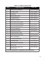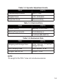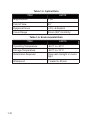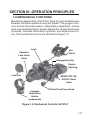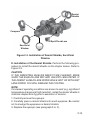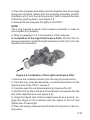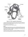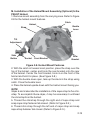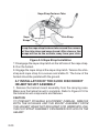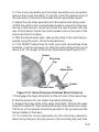
1
ATN PVS-7
NIGHT VISION GOGGLES
operator’s Manual (PVS-7) Revision 3 - APRIL 2009
o p e r a t o r ’s m a n u a l
Impor tant Expor t Restrictions ! Commodities,
products, technologies and services contained in
this manual are subject to one or more of the export
control laws and regulations of the U.S. Government
and they fall under the control jurisdiction of either the
US Department of State or the US BIS-Department
of Commerce. It is unlawful and strictly prohibited
to export, or attempt to export or otherwise transfer
or sell any hardware or technical data or furnish any
service to any foreign person, whether abroad or
in the United States, for which a license or written
approval of the U.S. Government is required, without
first obtaining the required license or written approval
from the Department of the U.S. Government having
jurisdiction. Diversion contrary to U.S. law is prohibited.
Manual (PVS-7) Revision 3 - April 2009
The information in this manual furnished for information use only, is subject to
change without notice, is not to be construed as a commitment by ATN Corp.
ATN Corp. assumes no responsibility or liability for any errors or inaccuracies that may appear in this book.
© 2009 ATN Corp. All right reserved.
SAFETY SUMMARY
CAUTIONS
• The ATN PVS-7 is a precision optical instrument and should be
handled carefully to prevent its damage.
• Do not scratch the external lens surfaces or touch them with your
fingers.
• To protect the image intensifier, keep the lens cap on the objective lens on when the device is not in use or when it is checked out
in daylight conditions.
• The IR illuminator produces a light that is invisible to a naked
eye for use in conditions of extreme darkness. However, this IR
light can be detected by somebody else who use a night vision
device.
• If you use the rubber eyecups for a long time period, you may
suffer from skin inflammation. If you find any symptoms, consult a
doctor immediately.
Caution :
This product contains natural rubber latex which
may cause allergic reactions.
a
NOTES
• Do not test the device in daylight conditions even with the daylight filter/lens cap on for more than ten (10) minutes.
• To protect the device from damage do not direct it to the bright
light sources (a fire, headlights of the automobile, lanterns, etc.).
• The purpose of the built-in IR illuminator is to view at close distances up to 3 meters when additional illumination is needed.
• The unit is equipped with the Automatic Shut-off System. This
system tracks when the unit is not used (the controls are not
touched for 60 minutes continuous) and shuts the unit off automatically.
To turn the unit on after automatic shut off, you need to rotate the
operation knob to the OFF position first and then to the ON position.
b
Equipment Limitations
To avoid physical and equipment damage when using the
ATN PVS-7, carefully read and understand the following equipment limitations.
• The equipment requires some night light (moonlight, starlight,
etc.) to operate. The level of equipment performance depends
upon the level of light.
• Night light reduces by passing through the clouds, while operating under trees, at building shadows, etc.
• The equipment is less effective when viewing into shadows and
other darkened areas.
• The equipment is less effective when viewing through the rain,
fog, sleet, snow or smoke.
• The equipment will not “see” through the dense smoke.
c
TABLE OF CONTENTS
i
SAFETY SUMMARY
pg.
a
CHAPTER 1: Introduction
Section I: General Information
1-1 Scope
1-2 Reporting Equipment Improvement
Recommendations (EIR) 1-3 Glossary
1-4 Administrative Stowage
Section II: Equipment Description
1-5 Equipment Characteristics, Capabilities
and Features 1-6 Equipment Capabilities
1-7 Specifications
Section III: Operation principles
1-8 Mechanical Functions
1-9 Optical and Electrical Functions
1-10 Consumable Items
CHAPTER 2: Operating Instructions Section I: Operating Procedures
2-1 General
2-2 Controls and Indicators
Section II: Preventive Maintenance Checks
and Services (PMCS)
2-3 Purpose of PMCS
2-4 Frequency of Performing PMCS
2-5 Performance of PMCS
Section III: Assembly and Preparation
2-6 Preparation of Use
2-7 Installation of the Quick Disconnect
Helmet Mount Assembly 2-8 Operating Procedures
2-9 Preparation for Stowage
1-1
1-2
1-2
1-2
1-2
1-4
1-5
1-5
1-8
1-8
1-11
1-11
1-12
1-13
2-1
2-2
2-2
2-2
2-5
2-5
2-5
2-5
2-10
2-10
2-20
2-22
2-29
CHAPTER 3: Maintenance Instructions
3-1
Section I: Troubleshooting Procedures
3-2
3-1 Troubleshooting
3-2
Section II: Maintenance Procedures
3-6
3-2 Cleaning the PVS-7
3-6
3-3 Head Mount Maintenance
3-6
APPENDIX A: System Optional Equipment A-1
FOR TECHNICAL INFORMATION
INFO-1
ii
iii
chapter 1
introduction
1-1
Section i: General Information
1-1 Scope
This manual provides operation and maintenance instructions for
the PVS-7 Night Vision Goggle (which shall be designated a goggle or PVS-7 throughout this manual). The PVS-7 is a self-contained night vision device that enables improved night vision using ambient light from the night sky (moon, stars, sky glow, etc.).
1-2 Reporting Equipment Improvement
Recommendations (EIR)
Reports from the user on recommendations for improvements are
encouraged. Send reports to the address below:
American Technologies Network Corp.
1341 San Mateo Avenue
South San Francisco, CA 94080
(800) 910-2862
(650) 989-5100
(650) 875-0129 fax
www.atncorp.com
[email protected]
1-3 Glossary
BLACK SPOTS. These arc cosmetic blemishes in the image intensifier of the PVS-7 or dirt or debris between the lenses.
BRIGHT SPOTS. These can be defects in the image area produced by the PVS-7 . This condition is caused by a flaw in the film
on the micro-channel plate. A bright spot is a small, non-uniform,
bright area that may flicker or appear constant. Bright spots usually go away when the light is blocked out and arc cosmetic blemishes that are signal induced.
BROWPADS. Three hook-and-pile browpads are provided to adjust the head mount to fit different head sizes. The thin brow pad
(fits on a large head) comes attached to the head mount and the
thick or medium (fits on a smaller head) brow pads are stored in
the carrying case.
1-2
CHICKEN WIRE. An irregular pattern of dark thin lines in the field
of view either throughout the image area or in parts of the image
area. Under the worst-case condition, these lines will form hexagonal or square wave-shaped lines.
DARK (OR DARK AREA). A place in which there is very little light.
It docs not mean total darkness. Generally, this means conditions
similar to a quarter- moon or starlit night.
DEMIST SHIELDS. The two demisting shields are used to prevent the eyepiece lenses from becoming fogged.
DIOPTER. A unit of measure used to define eye correction. Adjustments to the eyepiece focus ring will change diopter and provide a clearer image.
EDGE GLOW. There is a defect in the image area of the PVS-7.
Edge glow is a bright area (sometimes sparkling) in the outer portion of the viewing area.
EMISSION POINT. A steady or fluctuating pinpoint of bright light
in the image area that does not go away when all light is blocked
from the objective lens. The position of an emission point within
the image area does not move. An emission point should not be
confused with a point light source in the distance.
FIXED-PATTERN NOISE. This is a cosmetic blemish in the image area characterized by a faint hexagonal (honeycomb) pattern
throughout the viewing area that most often occurs at high light
levels or when viewing very bright lights. Fixed-pattern noise is inherent in the structure of the fiber optics and can be seen in every
image intensifier if the light level is high enough.
FLASHING. This is a defect in the image area of the PVS-7 . The
image appears to flicker or flash.
FLICKERING. See “flashing”.
IMAGE-INTENSIFIER ASSEMBLY. An electro-optical device that
detects and amplifies ambient light to produce a visual image.
INFINITY FOCUS. Adjustment of the objective lens so that a distant object, such as a star or the point light on a distant tower,
forms the sharpest image
1-3
INTERMITTENT OPERATION. This is a defect in the image area of
the PVS-7 . Sec “flashing”.
LIGHT INTERFERENCE FILTER (LIF). This is a tear-protection filter for the goggle. Use of this filter will result in a slight reduction in
system gain.
MICROCHANNEL PLATE. A current-multiplying optical disk that
intensifies the electron image produced by the photocathode.
PHOTOCATHODE. The input optic of an image intensifier that absorbs light energy and in turn releases electrical energy in the form
of an electron image.
SACRIFICIAL WINDOW. A replaceable sacrificial window is supplied to protect the objective lens assembly during operation in adverse conditions.
SCINTILLATION. A faint, random, sparkling effect throughout the
image area. Scintillation is a normal characteristic of the image
intensifier assembly and should not be confused with emission
points. Scintillation is more pronounced under low-light conditions.
Also called “video noise”.
SHADING. The viewed image should be a full circle. If shading is
present, you will not see a fully circular image. Shading is indicative
of a dying photocathode and is caused by a defective vacuum seal
of the image intensifier. Shading is very dark and you cannot see an
image through it.
1-4 Administrative Stowage
Administrative stowage of equipment should be done in the factory-supplied container and after a thorough PMCS as outlined in
Chapter 3 of this manual. This will ensure the PVS-7 remains in a
mission ready-condition during storage.
1-5 WARRANTY INFORMATION
This item shall conform to design, manufacturing, and performance
requirements and be free from defects in material and workmanship
for a period of two (2) years from the date of acceptance. If item is
defective, notify ATN or point of purchase contact.
1-4
Section II: Equipment Description
1-5 Equipment Characteristics,
Capabilities and Features
The PVS-7 includes the items shown in Figure 1-1. See Table 1-1
and Figure 1-1 for Standard and Optional Equipment.
A. Goggle Assembly. The goggle assembly consists of four primary sub-assemblies; a simple objective lens, a wired housing assembly, an image intensifier tube (IIT) assembly (not shown) and a
rear cover assembly. The wired housing assembly contains a builtin battery compartment, attached battery cap and the RESET/OFFON-IR/PULL switch.
B. Head mount Assembly. The adjustable, cushioned head mount
assembly secures the goggle to the operator’s head for night viewing providing freehand support for use with a weapon, protective
mask or other purposes. The thin brow pad (used for larger heads)
comes attached to the head mount and the thick or medium brow
pads (for smaller heads) arc stored in the carrying case.
C. Carrying Case. The canvas carrying case is provided for transportation and protection of the PVS-7, head mount assembly, batteries and accessories. Two slide keepers arc provided for belt
attachment A carrying case strap is also provided which can be
attached to the two D-rings on the back of the carrying case. The
case has a zipper closure.
D. Demist Shields. The two demist shields are used to prevent the
eyepiece lenses from becoming fogged.
E. Sacrificial Window. A replaceable sacrificial window is supplied to protect the objective lens during operation in adverse conditions.
F. IR Spot/Flood Lens. This item focuses the IR light for a narrow
beam (spot) or wide-angle (flood) beam illumination.
1-5
17*
1
18
13
4
5
2
16
3*
6
11*
15
12*
10
14
9
Figure 1-1. PVS-7 Components
1-6
8
Table 1-1. System Components
ITEM
DESCRIPTION
PART NO.
1
Head mount Assembly
ATN3144268
2
Thin Brow Pad
ATN3144280
3*
Compass
ATN3187430
4
Medium Brow Pad
ATN3144435
5
Large Brow Pad
ATN3144436
6
Operator’s Manual
PVS-OM-007
7
Lens Paper (Not Shown)
-
8
Shoulder Strap Assembly
ATN3144267
9
Light Interference Filter
ATN5009737
10
Sacrificial Window
ATN3144264
11*
IR Spot/Flood Lens
ATN3187441
12*
Image intensifier Tube
13
Demist Shield Assembly
ATN31442632
ATN-PVS7-001
14
PVS-7 Assembly
15
AA Alkaline Batteries
B-3058/U
16
Carrying Case
ATN3187392
17*
Helmet Mount Assembly
ATN3256390
18
Neck Cord
ATN3260933
19*
Shipping/Storage Case
(Not Shown)
ATN3187393
*Optional equipment or Equipment having variants
1-7
G. Compass. This item enables the operator to see azimuth readings in the goggle’s illumination viewing area.
H. Neck Cord. This additional authorized item enables the user
to attach the compass or 3X magnifier lens to his/her self to guard
against dropping or losing these items
I. Optional Equipment. Optional equipment includes demist
shields, sacrificial window. Light Interference Filter (LIF), compass,
helmet mount assembly and an IR spot/flood lens (see Figure 1-1).
Also included is a shipping and storage case. The PVS-7 may be
supplied in hard shipping and storage case. Batteries may also be
stored in the shipping and storage case.
1-6 Equipment Capabilities
The PVS-7 is a hand-held, head mounted or helmet mounted night
vision system that enables walking, driving, weapon firing, shortrange surveillance, map reading, vehicle maintenance and administering first aid in both moonlight and starlight. Each unit allows for
vertical adjustment (by using head straps), fore-and-aft adjustment,
objective lens focus, eyepiece focus and eye relief distance adjustment. The goggle also equipped with an infrared (IR) light-emitting
diode (or illuminator) and a low battery LED indicator. The goggle
automatically shuts off when disconnected from the head mount
or helmet mount or flipped up on the helmet mount. There is also a
high light cutoff feature that shuts off power to the goggle when it is
exposed to high levels of light for 70 (±30) seconds.
1-7 Specifications
The following tables provide information pertaining to the operational, electrical, mechanical, optical and environmental characteristics for the goggles.
1-8
Table 1-2. Operator Adjustment Limits
ITEM
LIMITS
Interpupillary Distance
55 to 71 mm
Diopter Focus
+2 to -6 diopters
Objective Focus
25 cm to infinity
Table 1-3. Electrical Data
ITEM
LIMITS
Power Source
Battery (3 VDC max.)
Battery Requirements
2 AA Alkaline or
1 Lithium (BA-5567/U)
Table 1-4. Mechanical Data
ITEM
LIMITS
Shipping and Storage Case
Size: Approx. 17 ”x12”x7 ”
Weight: 6.7 lbs.
Soft Carrying Case
Size: Approx. 14”x8”
Goggle (See NOTE)
Weight 1.5 lbs
NOTE
The weight of the PVS-7 does not include accessories.
1-9
Table 1-5. Optical Data
ITEM
LIMITS
Magnification
1.0X
Field of View
40°
Eyepiece Focus
+2 to -6 diopters
Focus Range
25 cm (9.8”) to infinity
Table 1-6. Environmental Data
ITEM
1-10
LIMITS
Operating Temperature
-40°C to +50°C
Storage Temperature
-50°C to +70°C
Illumination Required
Overcast starlight to moonlight
Waterproof
1 meter for 30 min.
Section III: Operation Principles
1-8 Mechanical Functions
Mechanical adjustments of the PVS-7 allow for physical differences
between individual operators using the system. The goggle’s functions include the power switch, interpupillary adjustment, release
latch, eye relief adjustment, diopter adjustment, IR spot/flood focus
(optional), compass illumination (optional), and objective lens focus. The mechanical controls are identified in Figure 1-2.
Latch
Objective
Lens Focus
Knob
Eye
Relief
Interpupillary Adj.
Diopter
Adj. Ring
Lens Cap
RESET/OFF-ONIR/PULL Swith
Knob
Compass
Illumination
Button
(underneath)
IR Spot/Flood Focus Knob
Figure 1-2. Mechanical Controls for PVS-7
1-11
1-9 Optical and electrical Functions
The optical functions include an objective lens, image intensifier, a
collimator lens and two eyepieces. The objective lens collects light
reflected from the night scene by the moon, stars or night sky and
inverts the image and focuses that image on the image intensifier.
The electrical functions include the following.
A. Power Source. The electronic circuit is powered by replaceable
batteries - either a 3.0 Volt lithium battery (BA-5567/U) or two AA
1.5 Volt alkaline batteries (BA-3O5S/U).
B. Electrical Principles. Power from the batteries is supplied to
the components through the RESET/OFF-ON-IR/PULL switch as
follows:
RESET/OFF Position. With the switch in the OFF position, the circuit is not energized either to the image intensifier or the IR illuminator. Also, turn the switch to this position to reset after automatic
shutoff or high light cutoff.
ON Position. Power is drawn from the battery compartment to energize the goggle. When the voltage drops to 2.4 VDC, a low battery
indicator at the right eyepiece blinks indicating approximately 30
minutes of operating time.
IR/PULL Position. Power is drawn from the battery compartment to
energize the goggle and IR light source and a steady red indicator
light in the left eyepiece. The IR is momentarily turned on by turning
the switch past ON without pulling the knob.
C. Automatic Shutoff. When the goggle is removed from the head
mount or helmet mount while in operation, they will automatically
shut off. This prevents enemy detection of the green glow of the
image intensifier. To turn the goggle back on, turn the switch to RESET/OFF and then to ON again.
D. High Light Cutoff. The goggle will automatically shut off after
70 (±30) seconds of operation in daylight or bright room light. Individual bright lights (headlights, flashlights or other concentrated
light sources) will not actuate the high light cutoff function unless
focused directly on the high light detector located on the front of the
1-12
goggle. To turn the goggle back on, turn the switch to RESET/OFF
position and then to ON again.
1-10 Consumable Items
Items listed in the Table 1-7 are recommended for operator maintenance.
Table 1-7. Consumable Items
ITEM
LIMITS
Lens Paper
-
Color Swabs
-
Alcohol
-
1-13
1-14
chapter 2
operating instructions
2-1
Section I: Operating Procedures
2-1 General
This section contains instructions for placing the PVS-7 in operation
and to operate it under normal conditions. The function of controls
and indicators is explained.
CAUTION
THE PVS-7 IS A PRECISION ELECTRO-OPTICAL INSTRUMENT
AND MUST BE HANDLED CAREFULLY AT ALL TIMES.
2-2 Controls and Indicators
The PVS-7 is designed to adjust for different users and corrects for
most differences in eyesight. The controls and indicators for the
PVS-7 are shown or described in Figure 2-1 and Tables 2-1 and
2-2.
12
7
10
11
1
5
4
6
3
Figure 2-1. PVS-7 Controls and Indicators
2-2
2
Table 2-1. Controls and Indicators
ITEMS
1
CONTROLS AND
INDICATORS
FUNCTIONS
RESET/ OFF- ON- Controls goggle and IR light powIR/PULL
er. ON or OFF.
RESET/ OFF Same as system
OFF. Also resets goggle after automatic shutoff or highlight cutoff.
ON Goggle activated.
IR/PULL Pull switch out and turn
clockwise to activate goggle and
IR. Illuminates LED indicator in left
eyepiece.
NOTE
Some PVS-7’s contain an additional momentary IR function. For
momentary IR, continue to turn the switch knob clockwise, past
ON and without pulling. The switch will return to the ON position
when released.
2
RESET/ OFF- ON- Defines the switch positions.
IR/PULL Label
3
IR Spot/Flood Lens
4
Compass Illumina- Pressing this button activates the
tor Button
compass illuminator LED which
makes compass readings visible
in the goggle viewing area. Additional pressure will make the
image brighter The image disappears when the button is released
Focuses the IR light for a narrow
beam (spot) or wide angel (flood)
beam illumination.
2-3
ITEMS
2-4
CONTROLS AND
INDICATORS
FUNCTIONS
5
Objective Focus
Focuses objective lens. Adjusts for
sharpest image of viewed object.
6
Battery Polarity In- The feature, molded into the PVSdicator
7, shows the proper orientation of
the batteries.
7
Latch
Latch used for separation of goggle assembly from head mount/
helmet mount assembly.
8
LED On Indicator
(Not Shown)
When illuminated (left eyepiece)
it indicates that the IR illumination
is on.
9
Low Battery Indica- When illuminated (right eyepiece)
tor (Not Shown)
it indicates a low battery condition
with less than 30 minutes of battery life remaining.
10
Diopter Adjustment Focuses eyepiece lens for each
Ring
eye without the need for glasses.
Adjusts for sharper image of intensifier screen.
11
Interpupillary Ad- Adjusts for distance bet ween
justment
eyes by sliding the eyepieces either together or apart so each eye
can observe the entire field at the
same time
12
Eye Relief
Adjusts the distance between your
eyes and the goggle.
Section II: Preventive Maintenance Checks and Services (PMCS)
2-3 Purpose of PMCS
PMCS is performed daily when the PVS-7 is in use to ensure that
the sight is ready at all times. Procedures are a systematic inspection of the goggle that will enable you to discover defects that might
cause the PVS-7 to fail on a mission.
2-4 Frequency of Performing PMCS
The frequency of PMCS performing PMCS is follows:
A. Daily when the PVS-7 is in use.
B. Weekly when in a standby condition.
C. Semi-annually when stored in depot or administrative stowage.
2-5 Performance of PMCS
Preventive maintenance checks and services shall be performed
following the sequence and inspection procedures indicated in
Table 2-2
Table 2-2. Preventive Maintenance Checks and Services
B = Before Operation; D = During Operation; A = After Operation
INTERVAL&
SEQUENCENO.
B
D
A
ITEM TO BE INSPECTED/
PROCEDURE
1
GOGGLE - Check for completeness, including accessories. Check for dirt and moisture
on external surfaces and parts. Clean and dry
with lint-free cloth.
2
SHIPPING CASE - Check for dirt, moisture
and mildew. Clean with mild detergent and water. Dry with lint-free cloth.
2-5
INTERVAL&
SEQUENCENO.
B
2-6
D
A
ITEM TO BE INSPECTED/
PROCEDURE
3
CARRYING CASE - Check for dirt, moisture
and mildew. Clean with mild detergent and water. Dry with lint-free cloth.
4
BATTERIES - Remove batteries. Check for
corrosion on terminals and dirt or moisture in
battery cap. Clean battery cap with dry cloth.
Replace batteries if corroded.
5
LENSES - Check for dirt and moisture. Clean
with lens paper or brush and/or alcohol and
cotton swabs
6
EYECUPS - Check for dirt, dust, cracked or
torn cups. Inspect for bent, broken or improperly fitting eyecup.
7
INTERPUPILLARY ADJUSTMENT - Slide
each eyepiece back and forth to check for
binding or looseness.
8
OBJECTIVE LENS FOCUS KNOB - Rotate
objective lens focus knob to ensure free movement (range is approximately 1/3 turn).
9
NECK CORD & LENS CAP- Check for cracked,
torn or missing lens cap. Inspect cord for cuts,
damage or frayed ends. Re-tie ends if necessary.
10
LATCH - Inspect for damage.
INTERVAL&
SEQUENCENO.
B
11
D
A
ITEM TO BE INSPECTED/
PROCEDURE
RESET/OFF-ON-IR/PULL SWITCH - Remove
any batteries and turn the switch from RESET/
OFF to ON or IR/PULL. Each position should
have a definite stopping point. Inspect for broken or missing knob.
HEAD MOUNT
12
STRAPS AND PADS - Check for cuts tears,
fraying, holes, cracks or defective fasteners.
13
SOCKET - Check for dirt, dust or corrosion.
Insert goggle latch into socket to verify secure
attachment of goggle to head mount. If necessary, clean socket with water.
14
FORE-AND-AFT ADJUSTMENT - Press the
socket-release button and check for free motion. Inspect for damage.
OPTIONAL HELMET MOUNT
15
STRAPS - Inspect for cuts; tears: fraying;
holes cracks or defective fasteners
13
SOCKET - Check for dirt, dust or corrosion.
Insert goggle latch into socket to verify secure
attachment of goggle helmet mount. If necessary, clean socket with water.
17
FORE-AND-AFT ADJUSTMENT - Press the
socket-release button and check for free motion. Inspect for damage.
18
FLIP-UP/AUTO OFF - With goggle on, flip-up
and verify auto off function operation.
2-7
INTERVAL&
SEQUENCENO.
B
D
A
ITEM TO BE INSPECTED/
PROCEDURE
19
TILT ADJUSTMENT - Verify knob locks tilt in
place and full range of tilt is available with knob
loosened.
20
SOFT CARRYING CASE - Remove all items
and shake out loose dirt or foreign material. Inspect for tears, cuts, excess wear or damage
to mounting clips.
21
SHOULDER STRAP ASSEMBLY - Inspect for
cuts, tears or excess wear of damaged clips.
NOTE
Damaged optional items (compass, IR spot/flood, sacrificial
window, demist shields) do not cause the entire end item to
be “not fully mission capable”. However, the damaged item
should be replaced as soon as practical to restore full capability of the system.
ACCESSORY ITEMS
2-8
22
DEMIST SHIELDS - Inspect for dirt, dust
scratches or damage. If necessary, clean
when shields are dry and with dry lens paper
only.
23
LIGHT INTERFERENCE FILTER (LIF) - Inspect for dirt dust, scratches or damage. If
necessary, clean with water and dry with lens
paper.
24
IR SPOT/FLOOD LENS - Rotate IR focus lens
to ensure free movement.
INTERVAL&
SEQUENCENO.
B
D
A
ITEM TO BE INSPECTED/
PROCEDURE
25
COMPASS ASSEMBLY - Inspect for dirt, dust
scratches or damage. If necessary, clean with
water and dry with lens paper.
Install compass assembly and turn on goggle.
When the illumination button is depressed, the
compass should be visible.
26
3X/5X AFOCAL MAGNIFIER LENS - Check
lens for scratches or damage. Check mating
to objective lens by screwing in or pressing on
with adapter installed.
2-9
Section III: Assembly and
Preparation
2-6 Preparation for Use
This chapter contains the information necessary to prepare the
goggle for operation. This includes unpacking, examination for
goggle damage, battery installation, sacrificial window installation
and head mount installation and adjustments.
A. Unpacking. The following steps must be accomplished prior to
each mission where the PVS-7 is used.
CAUTION
RELIEVE AIR PRESSURE INSIDE SHIPPING AND STORAGE CASE BY PRESSING RELIEF VALVE BUTTON LOCATED
NEAR THE CARRYING CASE HANDLE BEFORE RELEASING
LATCHES.
1. Release the two latches securing top of shipping and storage
case and open top.
2. Check contents of shipping and storage case for completeness.
(see Figure 1-1.)
3. Remove the carrying case from the shipping and storage case.
Open carrying case (Figure 1-1), remove the PVS-7 and check contents for completeness.
4. Inspect the goggle for obvious evidence of damage to optical
surfaces, body, eyecups. RESET/OFF-ON-IR/PULL switch, battery cap, etc. Ensure that all optical surfaces are clean and ready for
use. Clean with lens paper.
B. Installation of Batteries.
CAUTION
TO PROTECT THE IMAGE INTENSIFIED KEEP THE LENS CAP
ON THE OBJECTIVE LENS WHEN THE GOGGLE IS NOT IN USE
OR WHEN CHECKED OUT IN DAYLIGHT CONDITIONS.
NOTE
Operation of the PVS-7 under daylight conditions will activate the high
light cut off in 70 (±30) seconds, causing the goggle to shutdown.
2-10
WARNING
THE LITHIUM BATTERY CONTAINS SULFUR DIOXIDE GAS
UNDER PRESSURE.
DO NOT HEAT, PUNCTURE, DISASSEMBLE, SHORT CIRCUIT,
ATTEMPT TO RECHARGE OR OTHERWISE TAMPER WITH THE
BATTERIES.
TURN OFF EQUIPMENT IF BATTERY COMPARTMENT BECOMES
UNDULY HOT. IF POSSIBLE, WAIT UNTIL THE BATTERIES HAVE
COOLED BEFORE REMOVING THEM.
BATTERIES HAVE SAFETY VENTS TO PREVENT EXPLOSION.
WHEN THEY ARE VENTING GAS, YOU WILL SMELL IT (VERYIRRITATING) OR HEAR THE SOUND OF GAS ESCAPING. WHEN
THE SAFETY VENTS HAVE OPERATED, THE BATTERIES ARE
FAIRLY SAFE FROM BURSTING, BUT STILL MUST BE HANDLED
WITH EXTREME CARE BECAUSE OF HEAT.
IF YOU INHALE SULFUR DIOXIDE, SEEK MEDICAL ATTENTION.
The PVS-7 will operate with either of the two battery types identified
in Table 2-3. Batteries are not supplied with the PVS-7 and must be
obtained.
Table 2-3. Estimated Battery Life
BATTERY TYPE
NEGLIGIBLE
IR USAGE
IR USAGE 10%
OF THE TIME
Lithium (BA-5567/U)
47-85 Hours
36 - 65 Hours
AA Alkaline (BA-3058/U)
89-160 Hours
68 - 123 Hours
NOTE
The battery data in Table 2-3 represents operation under room temperature. When operating under cooler conditions, battery life will
decrease.
CAUTION
MAKE CERTAIN THE RESET/OFF-ON-IR/PULL SWITCH IS IN
THE OFF POSITION BEFORE INSTALLING BATTERIES.
Install either two (2) AA batteries or one (1) BA-5567/U lithium battery as follows. Do not attempt to mix battery types in the compartment.
2-11
1. Remove the battery cap by turning it counterclockwise.
2. Check to ensure the o-ring is present. If not, replace it.
3. Observe polarity, as indicated on the outside of the battery compartment, and insert either two AA, 1.5 Volt batteries or one 3.0 Volt
BA-5567/U lithium battery into the battery compartment, plus (+)
end first. (See Figure 2-2.)
4. Replace battery cap by pushing and turning it clockwise. Tighten
it firmly to ensure a watertight seal.
C. Installation of the Eyecups. Perform the following procedure to
install the eyecups onto the PVS-7. Refer to Figure 2-2.
1. Carefully press each eyecup over the diopter cell retainer.
2. Rotate each eyecup into proper viewing position. Adjust for best
eye fit. The eyecups must seal around your eyes and prevent the
green glow from escaping.
Alkaline
Batteries
(size AA)
Lithium
Battery
Battery Cup
with O-ring
Eyecup
Figure 2-2. Battery and Eye cap Installation
2-12
Demist
Shields
Compass
IR Spot/Flood Lens
Sacrificial
Window
LIF
Figure 2-3. Installation of Demist Shields, Sacrificial
Window
D. Installation of the Demist Shields. Perform the following procedure to install the demist shields on the diopter lenses. Refer to
Figure 2-3.
CAUTION
IF THE DEMISTING SHIELDS NEED TO BE CLEANED, MAKE
SURE THE SHIELDS ARE DRY AND USE DRY LENS PAPER. IF
THE DEMIST SHIELDS ARE WIPED WHILE WET OR WITH WET
LENS PAPER, YOU WILL DAMAGE THE COATING.
NOTE
If inclement operating conditions are known to exist (e.g. significant
temperature change and high humidity), install the demist shields to
minimize diopter lens fog prior to execution of mission.
1. Carefully remove the eyecups.
2. Carefully press a demist shield onto each eyepiece. Be careful
not to smudge the eyepieces or demist shields.
3. Replace the eyecups (see paragraph 2-6, C).
2-13
E. Installation of the sacrificial Window. Perform the following
procedure to install the sacrificial window. Refer to Figure 2-3.
CAUTION
IF ADVERSE OPERATING CONDITIONS (DUST OR SAND),
ARE KNOWN TO EXIST, ATTACH THE SACRIFICIAL WINDOW
TO PROTECT THE OBJECTIVE LENS FROM SCRATCHES OR
OTHER DAMAGE.
1. If the compass assembly or lens cap is in place, remove it.
2. Carefully push the sacrificial window over the objective lens until it stops. Turn the sacrificial window clockwise until it snaps into
place.
F. Installation of the Compass Assembly.
Figure 2-4. Installation of Compass
NOTE
a. Prepare the PVS-7 for operation (paragraph 2-6).
b. Leave LIF in place when installing the compass assembly.
c. Ensure the Neck cord is secured to the compass and clothing
before installing.
1. If the sacrificial window or lens cap is in place, remove it.
2. Turn the PVS-7 on.
3. Rotate the objective lens focus completely counterclockwise
(while looking through the goggle).
2-14
4. Press the compass assembly onto the objective lens at an angle
using your left hand. Slowly turn the compass assembly counterclockwise until it is in the vertical position (with compass illumination button pointing down). See Figure 2-3.
5. Ensure that the compass fits tightly to the PVS-7.
NOTE
The o-ring must be in place in the compass assembly in order for
the compass to fit properly.
6. Refer to paragraph 2-6, F for operation of the compass.
G. Installation of the Light Interference Filter. Perform the following procedure to install the light interference filter (LIF) onto the
objective lens assembly.
Figure 2-5. Installation of the Light Interference Filter
1. Remove the container/wrench from the carrying case pouch.).
2. If the lens cap, compass assembly, or sacrificial window is on the
objective lens of the PVS-7, remove it.
3. Carefully open the container/wrench and remove the LIF.
4. Hold the LIF by the notched end and thread it clockwise into the
end of the objective lens (see Figure 2-5).
5. Using the ridged side of the container/wrench as a wrench, engage the ridges on the container with the ridges on the LIF and
tighten the LIF hand tight.
6. Place the empty container/wrench back into the pouch in the carrying case.
2-15
7. Replace the lens cap or the sacrificial window onto the end of the
objective lens and over the LIF.
CAUTION
BE CAREFUL NOT TO TOUCH THE GLASS SURFACES. IF YOU
GET FINGERPRINTS OR CONTAMINATION ON THE GLASS
SURFACES, USE LENS PAPER TO CLEAN THE LIF. IF MOISTURE IS NEEDED, USE YOUR BREATH TO MIST THE SURFACE
OF THE GLASS.
DO NOT OVER-TIGHTEN THE LIF INTO THE OBJECTIVE LENS.
NOTE
The lens cap, compass assembly, or the sacrificial window will fit
onto the end of the objective lens with the LIF in place.
H. Installation of the IR Spot/Flood Lens.
1. Press the IR spot/flood lens over the IR source until it is tight
against the goggle. Refer to Figure 2-6.
Figure 2-6. Installation of the IR Spot/Flood Lens
I. Installation and Adjustment of the Head Mount Assembly.
Perform the following procedures for donning the head mount.
NOTE
Do not don the head mount while the PVS-7 is attached to it.
2-16
Browpad
Neckpad
Headband
Socket
Assembly
Socket
Release
Button
Chin Cup
Chin Strap
Adjustment
Sliding Bar
Buckles
Figure 2-7. PVS-7 Head Mount Adjustments
1. Prior to donning the head mount, loosen the four chin straps so
the ends of each strap arc approximately two inches from the sliding bar buckles (See Figure 2-7)
2. Snap the front and rear snaps in place.
NOTE
If the head mount is too loose, remove the attached thin brow pad
and replace with either the medium or large brow pad, stored in the
carrying case. Refer to Chapter 3, paragraph 3-4 for removal and
replacement of the brow pads.
3. With both hands, grasp the neck pad assembly and pull the harness over your head and the neck pad down to the back of your neck.
2-17
4. Holding the chin cup in position on chin, adjust both rear chin cup
assembly straps until you feel light pressure against your chin. (DO
NOT TIGHTEN).
5. Maintain the position of the chin cup and remove any slack from
the front and rear chin straps. (DO NOT TIGHTEN).
6. Ensure that the cross-strap assembly is not twisted and remove
slack by adjusting the vertical adjustment strap at the neck pad.
7. Adjust chin strap and vertical adjustment until the chin cup and
headband assembly arc in comfortable but firm position.
NOTE
After installing the PVS-7, minor strap adjustments may be necessary to achieve comfort.
8. Refer to paragraph 2-7, A for operating procedures of head mount
assembly.
J. Installation of Head Mount Assembly with Protective Mask.
Perform the following procedures for donning the head mount with
a protective mask.
1. Place protective mask on your head per the instructions provided
with the mask.
WARNING
WHEN INSTALLING THE HEAD MOUNT OVER THE PROTECTIVE
MASK, BE CAREFUL NOT TO BREAK THE PROTECTIVE MASK
SEAL AROUND YOUR FACE.
2. Install the head mount assembly per instructions in paragraph
2-6, I.
NOTE
It may be necessary to remove the brow pad when wearing the head
mount over a protective mask.
K. Installation of the Head Mount Assembly with the PASGT
Helmet. Install the head mount assembly per the instructions in
paragraph 2-6, I.
L. Installation of the Head Mount Assembly with the M1 Helmet.
Install the head mount assembly per the instructions in paragraph
2-6. I.
2-18
M. Installation of the Helmet Mount Assembly (Optional) to the
PASGT Helmet.
1. Remove mount assembly from the carrying case. Refer to Figure
2-8 for the helmet mount features.
Helmet
Strap
Catch
Buckle
Lever
Tilt
Adjustment
Side
Button
Socket
Front Bracket
Rear
Bracket
Figure 2-8. Helmet Mount Features
2. With the catch in forward most position, place the strap over the
top of the helmet, center and hook the rear bracket onto the rear
of the helmet. Center the front bracket, hook in on the front of the
helmet and hold it in place. (See Figure 2-8.)
3. With the buckle-lever open, take up the slack in the strap using
catch. Close the buckle lever.
4. Place the helmet upside down with the helmet mount facing you.
NOTE
Steps 5 and 6 describe the installation of the nape strap to the chinstrap. To accomplish these steps, it may he necessary to unthread
the chinstrap from the helmet.
5. Thread the chinstrap through the right end of nape strap and
snap nape strap fastener tab closed. (Refer to Figure 2-9.)
6. Thread chin strap through the left end of nape strap and snap
nape strap fastener tab closed. (Refer to Figure 2-9.).
2-19
Nape Strap Fastener Tabs
Nape
Straps
Chin Strap
Loop the nape strap fastener tabs around the corners
of the chin strap and snap closed. After closure, the
snaps will be on the outside, away from your chin.
Figure 2-9. Nape Strap Installation
7. Disengage the nape strap latch on the left side of the nape strap.
8. Don the helmet.
9. Engage the nape strap at the nape strap latch. Tension the chinstrap and nape strap for a secure and stable fit. The brow of the
helmet should be parallel with the ground.
2-7 Installation of the Quick Disconnect
Helmet Mount Assembly
1. Remove the helmet mount assembly from the carrying case.
Make sure the helmet mount is complete. Refer to Figure 2-10 for
the helmet mount components and features.
CAUTION
TO PREVENT POSSIBLE EQUIPMENT DAMAGE, REMOVE
BOTH THE GOGGLES AND THE MOUNT ASSEMBLY FROM
THE HELMET WHEN NOT REQUIRED FOR IMMEDIATE USE.
THE CLIP/STRAP ASSEMBLY CAN REMAIN IN PLACE ON THE
HELMET.
2-20
2. If the mount assembly and clip/strap assembly are connected,
remove the mount assembly. To do this, push the release lever at
the top center of the mount and slide the two assemblies apart.
3. Adjust the clip/strap assembly to fit the helmet size being used.
4. With the catch in the most extended position, place the strap over
the top of the helmet, center and hook the rear bracket onto the
rear of the helmet. Center the front bracket hook on the front of the
helmet and hold it in place.
5. With the buckle lever open, take up the slack in the clip/strap assembly using the catch. Close the buckle lever.
6. If the PASGT helmet has its cloth cover and camouflage strap
installed, it will be necessary to slide the camouflage strap up (at
about a 30°-45° angle) at the front of the helmet (see Figure 2-10).
Helmet
Mounting
Clip
Tilt
Adjustment
Socket
Release Lever
Figure 2-10. Quick Disconnect Helmet Mount Features
7. Disengage the nape strap latch on the left side of the nape strap.
8. Don the helmet. Do not fasten the helmet chinstrap.
9. Engage the nape strap at the nape strap latch. Tension the nape
strap for a stable fit, then install and tension the helmet chin-strap.
The brow of the helmet should be parallel to the ground and the
helmet stable on the head.
10. To install the mount assembly into the clip/strap assembly,
place its top flange to the top groove of the mounting clip and then
2-21
press to the mount assembly bottom until it locks into place with a
click (see Figure 2-10).
2-8 Operating Procedures
This section contains operating procedures for using the PVS-7 as
a hand-held, head mounted or helmet mounted goggle. Prior to operating the goggle, ensure that all the steps in paragraph 2-6 have
been read and performed.
A. Head Mounted Operation. Perform the following procedures
for head mounted operation.
CAUTION
OPERATE THE PVS-7 ONLY UNDER DARKENED CONDITIONS
OR USE THE LENS CAP TO COVER THE OBJECTIVE LENS FOR
DAYLIGHT CONDITIONS.
NOTE
Proper objective focus cannot be obtained while the objective
lens cap with pinhole is covering the objective lens. Proper objective focus must be done in the dark with the objective lens cover
removed.
1. Ensure that the batteries are installed per paragraph 2-6, B.
2. Don the head mount per instructions in paragraph 2-6, I.
NOTE
Paragraphs 2-6, J, 2-6, K and 2-6, L provide additional information
required when installing the head mount with a protective mask,
PASGT or M1 helmet.
To make it easier to align the goggle, eyecups and diopter eyepieces to the eyes, depress the socket-release button (See Figure 2-8)
and slide the head mount socket all the way forward before attaching the goggles.
3. Align the PVS-7 ‘s latch (Figure 2-1) to the head mount socket
(See Figure 2-8). Press and hold down the latch lever while installing the goggle into the head mount socket. Release the latch when
the goggle is fully engaged in the socket.
2-22
4. Set your eye relief by depressing the socket-release button and
move the PVS-7 back toward your eyes until the eyecups comfortably seal around your eyes.
5. Turn the RESET/OFF-ON-IR/PULL switch ON.
6. Adjust the interpupillary distance (Figure 2-1) by sliding the eyepieces together or apart so each eye can observe the entire field of
view at the same time. The eyepieces adjust independently.
7. Readjust the vertical strap assembly (see Figure 2-7) for vertical
adjustment of the head mount until the PVS-7 is properly aligned
with your eyes.
NOTE
The sharpest image will be observed only when the objective lens
and both eyepieces are properly focused. The objective lens focus adjustment is used to focus on objects at varying distances.
The diopter adjustment rings are used to focus your eyes (without
glasses) on the image intensifier screen. These adjustments operate independently and must be made separately.
8. Fold the right eyecup over the eyepiece with your right thumb or
forefinger to obstruct the view through the right eyepiece. Rotate
the left diopter adjustment ring for the clearest view of the image
intensifier screen.
9. Fold the left eyecup over the eyepiece with your left thumb or
forefinger to obstruct the view through the left eyepiece. Rotate the
right diopter adjustment ring for the clearest view on the image intensifier screen.
10. Adjust the eye relief distance by pressing the socket release
button (See Figure 2-1) and sliding the PVS-7 fore or aft to obtain
a full field of view of the image. Readjust the diopter rings for best
image.
NOTE
Any readjustment of eye relief requires readjustment of the diopter
rings.
11. Adjust the objective lens focus (Figure 2-1) while observing an
object until the sharpest image is obtained.
2-23
B. Helmet Mounted Operation. Perform the following procedures
for helmet mounted operation.
1. Ensure that batteries are installed per paragraph 2-6, B.
2. Don the helmet mount per instructions in paragraph 2-6. M.
3. Place the PVS-7 in the socket of the helmet mount. (See Figure
2-8.) Set your eye relief by depressing the side buttons and carefully move the goggles fore or aft until the eyecups comfortably seal
around the eyes. Readjust the helmet straps as required for vertical
adjustment.
4. Turn power switch to ON. Adjust the tilt by using the tilt adjustment lock knob (Figure 2-1) until you obtain a comfortable viewing
angle.
5. Adjust the interpupillary distance (Figure 2-1) by sliding the eyepieces together or apart so each eye can observe the entire field
of view at the same time. The eyepieces adjust independently. If
necessary, readjust the eye relief.
NOTE
The sharpest image will be observed only when the objective lens
and both eyepieces are properly focused. The objective focus
adjustment is used to focus on objects at varying distances. The
diopter adjustment rings are used to focus your eyes (with or without glasses) on the image intensifier screen. These adjustments
operate independently and must be made separately.
6. Fold the right eyecup over the eyepiece with your right thumb or
forefinger to obstruct view through the right eyepiece. Rotate the
left diopter adjustment ring for the clearest view on the image intensifier screen.
7. Fold the left eyecup over the eyepiece with your left thumb or
forefinger to obstruct view through the left eyepiece. Rotate the
right diopter adjustment ring for the clearest view on the image intensifier screen.
K. Adjust the eye relief distance by pressing the socket release button (see Figures 2-1) and sliding the PVS-7 fore or aft to obtain a
full field of view of the image. Readjust the diopter rings for the best
image.
2-24
NOTE
Any readjustment of eye relief requires readjustment of the diopter
rings.
9. Adjust the objective lens focus (Figure 2-1) while observing an
object until the sharpest image is obtained.
10. To flip up, place an open hand under the goggle, grasp the
goggle and rotate up and rearward until the latch is firmly engaged
(Figure 2-11).
Figure 2-11. Flip-up Helmet Mount
NOTE
The PVS-7 will be turned off automatically when flipped up. The
PVS-7 will not turn on automatically when flipped down.
11. To flip down, grasp the goggle housing and rotate down and
forward until the latch is firmly engaged.
12. Turn the switch to the RESET/OFF position, then to the ON position to resume viewing.
C. Hand-Held Operation
CAUTION
OPERATE THE PVS-7 UNDER DARKENED CONDITIONS ONLY
OR USE HE LENS CAP TO COVER THE OBJECTIVE LENS FOR
DAYLIGHT CONDITIONS.
NOTE
When using the PVS-7 without a mounting device, make sure to
place the neck cord around your neck.
2-25
1. Ensure that the batteries are installed per paragraph 2-6, B.
2. Turn the RESET/0FF-ON-IR/PULL switch to ON.
3. Adjust the interpupillary distance (Figure 2-1) by sliding the eyepieces together or apart so each eye can observe the entire field of
view at the same time. The eyepieces adjust independently.
NOTE
The sharpest image will be observed only when the objective lens
and both eyepieces are properly focused. The objective focus
adjustment is used to focus on objects at varying distances. The
diopter adjustment rings are used to focus your eyes (with or without
glasses) on the image intensifier screen. These adjustments operate independently and must be made separately.
4. Hold the PVS-7 with your left hand and fold the left eyecup over
the eyepiece with your left thumb or forefinger to obstruct view
through the left eyepiece. Rotate the right diopter adjustment ring
for the clearest view on the image intensifier screen.
5. Hold the PVS-7 with your right hand and fold the right eyecup
over the eyepiece with your right thumb or forefinger to obstruct
view through the right eyepiece. Rotate the left diopter adjustment
ring for the clearest view on the image intensifier screen.
6. Readjust the objective lens assembly while observing an object
until the sharpest image is obtained.
D. Operation with Compass Assembly
NOTE
The objective lens focus can be fine tuned after installation, but in
order to obtain an accurate reading, the compass must be vertical.
(The compass image must be level).
1. Install per paragraph 2-6, F.
2. If necessary, to more clearly view your distant object, adjust the
objective focus slightly by gripping the compass and turning clockwise.
3. To view the compass through the PVS-7, grip the compass with
index finger on top and thumb on illumination button on the bottom
2-26
(Figure 2-4). Press button slightly with thumb until proper brightness
is obtained. The image should appear as shown in Figure 2-12.
Figure 2-12. View Through Installed Compass
NOTE
Increase brightness slowly: if brightness is increased too quickly,
excessive brightness may burn a temporary image into the image
intensifier. The goggle must be focused at or near infinite for proper
compass operation.
4. The compass readings should change when you move your head
from side to side. Rotate or tap compass slightly to ensure compass
is operating correctly. Hold the PVS-7 in a level position to assure
live rotation of the compass scale.
WARNING
THE COMPASS ILLUMINATOR CAN BE SEEN BY OTHERS USING
NIGHT VISION DEVICES.
NOTE
The compass reading is the magnetic North, not true North. The
compass reading is within 2° of correct absolute magnetic bearing.
Compass readings with a mounted PVS-7 (head mount or helmet
mount) can be up to ±15° of correct absolute, magnetic bearing.
This occurs most in the East (90°) to West (270°) and less in the
North (0°) to South (360°) reading. If the compass is inadvertently
magnetized this could cause an additional 15° error.
2-27
5. The tick mark closest to the center of the lighted display is the
compass bearing. The tick marks are in degrees, with longer marks
every five degrees and bearing labels every 10 degrees.
E. Use of the 3X or 5X Magnifier Lens Assembly. The 3X or 5X
magnifier lens assembly can be threaded directly into the 1X objective lens, with the light interference filter (LIF) and sacrificial window
removed. It can also be threaded into the focus ring adapter and
slipped on over the end of the objective lens with the LIF installed.
NOTE
The Neck cord can be used to tether the magnifier to your person to
prevent losing the lens if it is dropped. To use the Neck cord, tie the
end without the clip tightly around the magnifier and attach the clip
to a buttonhole, belt loop or other convenient point.
Figure 2-13. PVS-7 with Magnifier Lens Assembly Installed
F. Infrared (IR) Operations
WARNING
THE IR ILLUMINATOR IS A LIGHT THAT IS INVISIBLE TO THE
UNAIDED EYE FOR USE DURING CONDITIONS OF EXTREME
DARKNESS. HOWEVER, THE LIGHT FROM THE ILLUMINATOR
CAN BE DETECTED BY THE ENEMY USING NIGHT VISION
DEVICES.
1. Pull the RESET/OFF-ON-IR/PULL switch knob (Figure 2-1) out
and rotate clockwise to the IR position. With the PVS-7 held to the
eyes, observe that a red light appears in the left eyepiece. This in2-28
dicates that the IR illuminator is operating. When spring loaded momentary IR position is used, the illuminator should only flash on.
2. To Operate with the IR Spot/Flood Lens: Pull the RESET/OFFON-IR/PULL switch knob out and rotate clock-wise to the IR position. With the PVS-7 held to the eyes, turn the IR spot/flood until you
have achieved the optimum illumination of the desired distance.
Turn the RESET/OFF-ON-IR/PULL switch counterclockwise to the
ON position. Observe that the red indicator disappears.
2-9 Preparation for Stowage
A. Shutdown. Perform the following procedures to shut down the
PVS-7.
1. Turn the RESET/OFF-ON-IR/PULL switch to the OFF position.
2. Remove the PVS-7 from the head mount or helmet mount (if so
equipped) by depressing the latch lever (Figure 2-1) and removing
the PVS-7 from the head mount socket.
B. Packaging After Use.
1. Unscrew the battery cap and remove the battery(ies).
2. Inspect the battery compartment for corrosion or moisture. Clean
and dry if necessary.
3. Replace the battery cap.
4. Remove the demist shields, sacrificial window or compass assembly if installed. Install the lens cap.
NOTE
Prior to placing the PVS-7 assembly into the carrying case, ensure
the goggle and case are free of dirt, dust and moisture.
5. Place demist shields, batteries, carrying case strap, lens paper,
sacrificial window, manual, LIF, brow pads, head mount, helmet
mount and compass into the carrying case (see Figure 1-1).
6. Place the PVS-7 (objective lens down) into the shallow pocket of
the carrying case.
7. Place the carrying case into the shipping/storage case (Figure
2-14); close and latch it.
2-29
8. Return to storage area.
Figure 2 - 14. PVS-7 Shipping/storage case
2-30
chapter 3
maintenance instructions
3-1
Section I: Troubleshooting
Procedures
3-1 Troubleshooting
Table 3-1 lists common malfunctions that you may find with your
equipment. Perform the tests, inspections and corrective actions in
the order they appear in the table.
This table cannot list all the malfunctions that may occur, all the
tests and inspections needed to find the fault, or all the corrective
actions to correct the fault. If the equipment malfunction is not listed
or actions listed do not correct the fault, notify your maintainer.
Table 3-1. Operator’s Troubleshooting
MALFUNCTION
TEST / INSPECTION
1. Goggle fails Visual
to activate
C h e c k for d efe c tive, missing or improperly installed
battery(ies)
2. IR indicator Visual
fails to activate
CORRECTIVE ACTION
Turn switch to RESET/
OFF position and then
ON
Replace battery(ies) or
install correctly
If PVS-7 still fails to activate, refer to higher level
of maintenance
Refer to higher level of
maintenance
3. Poor image Check objective lens Refocus
quality
or eyepiece focus
Check for fogging or
dirt on lens
3-2
Clean lens surface
MALFUNCTION
TEST / INSPECTION
CORRECTIVE ACTION
4. Light visible Check eye relief dis- Readjust for proper eye
around eyecup tance
relief distance
Check eyecup for
resiliency
If eyecups defective, refer to higher level of maintenance
5. Diopter ad- Check to see if the If damaged, refer to highjustment can- diopter adjustment er level of maintenance
not be made
ring is bent or broken
6. Inter pupil - Defective eyepiece Refer to higher level of
l a r y a d j u s t - assembly
maintenance
ment cannot
be made (left &
right eye)
7. Battery cap Check for dirt or grit
difficult to turn
in threads
Clean
Visually inspect for If o-ring is missing: refer
the presence of an to higher level of mainteo-ring
nance
C h e c k f o r d a m - If damaged, refer to highaged battery cap or er level of maintenance
threads on battery
compartment
8. PVS-7 does Visual
not shut off
when removed
from head
mount during
operation
Return both the PVS-7
and head mount to higher
level of maintenance
3-3
3-4
MALFUNCTION
TEST / INSPECTION
CORRECTIVE ACTION
9. Head straps
cannot be tightened
Check for defective If damaged, refer to highbuckles, fasteners er level of maintenance
or straps
10. Head
mount or
helmet mount
socket and
goggle do not
catch
Check socket or
latch for dirt
Clean socket and latch
Check socket or
latch for damage
If damaged; return both
head mount or helmet
mount and PVS-7 to
higher level of maintenance
11. Helmet
mount will
not tighten to
helmet
Visual
If damaged, refer to
higher level of maintenance
12. LIF will not
thread in or
obstructs view
Check for dirt in
threads
Clean threads
Check for damaged
assembly
If damaged, refer to
higher level of maintenance
13 . I R s p o t / Visual
flood lens will
not adjust
Refer to higher level of
maintenance
14. Compass
does not illuminate
Visual
Refer to higher level of
maintenance
15 C o m p a s s
will not stay on
the PVS-7
Visual
Possibly missing an oring
Refer to higher level of
maintenance
MALFUNCTION
TEST / INSPECTION
16 C o m p a s s Visual
display is not
clear
17. PVS-7 does
not shut off
when exposed
to high light test
under day light
or bright room
light.
CORRECTIVE ACTION
Make sure the PVS-7 is
focused for infinity. If so
and compass display is
still not clear refer to higher level of maintenance
Perform the following tests under day
light or bright room
light
Place the lens cap
on the objective
lens. Tur n PVS -7
on and observe that
they shut off within
70 (± 30 ) seconds
after energized
Turn goggle off and If damaged, refer to highthen on to re-ener- er level of maintenance
gize
3-5
Section II: Maintenance Procedures
3-2. Cleaning the PVS-7
CAUTION
THE PVS-7 IS A PRECISION ELECTRO-OPTICAL INSTRUMENT
AND MUST BE HANDLED CAREFULLY. DO NOT SCRATCH THE
EXTERNAL LENS SURFACES OR TOUCH THEM WITH YOUR
FINGERS.
Clean the goggle with water if necessary and dry thoroughly. Clean
lenses with lens paper (and water if necessary, except for demist
shields).
CAUTION
WIPING DEMIST SHIELDS WITH LENS PAPER WHILE WET CAN
DAMAGE THE COATING.
3-3. Head Mount Maintenance
A. Brow Pad Replacement. Replace the brow pad when cracked,
torn or contaminated. Perform the following procedure to remove
and replace the brow pads.
CAUTION
FOR PROTECTION OF THE IMAGE INTENSIFIER, DISCONNECT
THE PVS-7 FROM THE HEAD MOUNT PRIOR TO REPLACING
BROW PADS.
1. Firmly grasp the head mount and remove the old brow pad.
2. Gently press on the new brow pad. Lightly smooth out any wrinkles in the new brow pad.
B. Neck Pad Re-installation. During operation of the goggle, it
is possible for the neck pad to become separated from its position
on the headband. Perform the following procedure to reinstall the
neck pad.
1. Lift the upper headband strap retention tab (see Figure 3-1) allowing the neck pad strap to be inserted underneath.
2. Slip the neck pad strap all the way under the upper strap retention tab and then pull the lower part of the neck pad strap under the
lower strap retention.
3-6
Lower Strap
Retention Tab
Lower Strap
Retention Tab
Lower Strap
Retention Tab
Figure 3-1. Re-installing the Neck Pad
3. Repeat steps 1 and 2 for the other side of the headband and neck
pad if necessary.
C. Lacing the Sliding Bar Buckles. While donning and adjusting the head mount, it is possible for a strap to slip out of a slide
fastener. Perform the following procedure to replace the strap and
sliding bar buckle.
1. Thread the strap from the inside of the buckle over the moveable sliding bar (see Figure 3-2). Thread the strap back through the
buckle but this time under the sliding bar and over the serrated part
of the buckle.
2. Pull the strap through the buckle and tighten as necessary.
3. Repeat steps 1 and 2 for any other straps and buckles that may
have come undone.
Moveable
Sliding Bar
Fixed
Serrated Bar
Figure 3-2. Lacing the Sliding Bar Buckles
3-7
APPENDIX A
System Optional Equipment
Table A-1. System Optional Equipment
ITEM
A-1
DESCRIPTION
QUANT
PART NO
1
Helmet Mount Assy.
1
ATN3256390
2
Objective Filter Assy., LIF
1
ATN5009737
3
Sacrificial Window Assy.
1
ATN3144264
4
Demist Shield Assy.
2
ATN31442632
5
Case, Shipping/Storage
1
ATN3187393
6
Battery, Lithium
1
B-5567/U
7
3X A local Lens Assy.
1
ATN5009717
8
Kit Adapter, 3X Afocal, 7D
1
ATN5009718
9
5X Afocal Lens Assy.
1
ATN5009719
10
Kit Adapter, 5X Afocal, 7D
1
ATN5009720
11
Obj. Lens., 3X, 7D
1
ATN5009721
12
Obj. Lens., 4X, 7D
1
ATN5009722
13
Obj. Lens., 6X, 7D
1
ATN5009723
14
Sacrificial Filter Assy.. 75mm
1
ATN3144265
15
Sacrificial Filter Assy., 108mm
1
ATN3144266
16
Sacrificial Filter Assy., 162mm
1
ATN3144267
17
Lens Cover Assy., 75mm
1
ATN5009724
18
Lens Cover Assy., 108mm
1
ATN5009725
19
Lens Cover Assy., 162mm
1
ATN5009726
20
Tripod Adapter Assy., (4X/6X)
1
ATN3187394
21
Shipping Case Assy.
1
ATN3187395
22
Mount Assy., 7D-SPH-5CG
1
ATN3187396
23
Objective Lens Assy., 54mm
1
ATN5009710
For Technical Information
ATN Corp.
1341 San Mateo Avenue
South San Francisco, CA 94080
(800) 910-2862
(650) 989-5100 tel.
(650) 875-0129 fax
www.atncorp.com
[email protected]
INFO-1
For note
INFO-2
INFO-3
16032011
For customer service and technical support, please contact
American Technologies Network Corp.
North American Office
1341 San Mateo Avenue, South San Francisco, CA 94080
phone: 800-910-2862, 650-989-5100; fax: 650-875-0129
European Office
The following countries can use our toll free number:
00 800 9102-8620
Austria, France, Germany, Holland, Italy, Spain, Sweden, Switzerland
For other countries, please use
38 048-7770214 or 38 048-7770345
www.atncorp.com
©2009 ATN Corporation