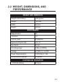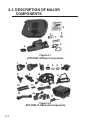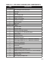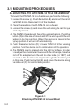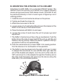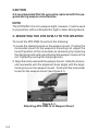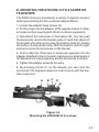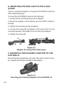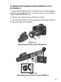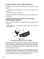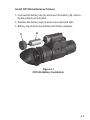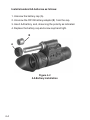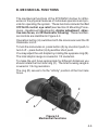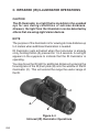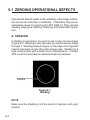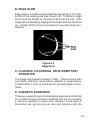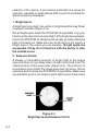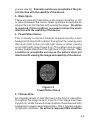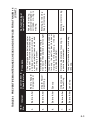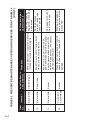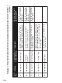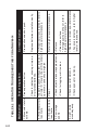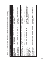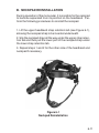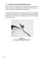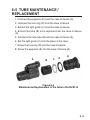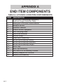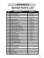
1
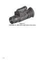
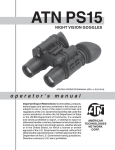
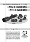
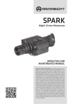
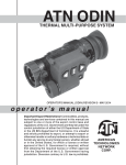
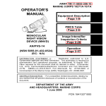
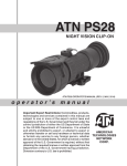
ATN NVM14
Mfg’s P/Ns:
ATN NVM-14-2 (Gen2+)
ATN NVM-14-2I (Gen2+)
ATN NVM-14-CGT (Gen2+)
ATN NVM-14-HPT (Gen2+)
ATN NVM-14-3 (Gen3)
ATN NVM-14-3A (Gen3)
ATN NVM-14-4 (Gen4)
o p e r a t o r s ’s m a n u a l
Important Export Restrictions! Commodities, products,
technologies and services contained in this manual are
subject to one or more of the export control laws and
regulations of the U.S. Government and they fall under the
control jurisdiction of either the US Department of State
or the US BIS-Department of Commerce. It is unlawful
and strictly prohibited to export, or attempt to export or
otherwise transfer or sell any hardware or technical data or
furnish any service to any foreign person, whether abroad
or in the United States, for which a license or written
approval of the U.S. Government is required, without
first obtaining the required license or written approval
from the Department of the U.S. Government having
jurisdiction. Diversion contrary to U.S. law is prohibited.
Manual (NVM14-004) Revision 4 - February 2008
The information in this manual furnished for information use only, is subject to
change without notice, is not to be construed as a commitment by ATN Corp.
ATN Corp. assumes no responsibility or liability for any errors or inaccuracies that may appear in this book.
© 2008 ATN Corp. All right reserved.
SAFETY SUMMARY
CAUTIONS
• The ATN NVM-14 is a precision optical instrument and must be
handled carefully at all times to prevent damage.
• Do not scratch the external lens surfaces or touch them with
your fingers.
• Wiping demisting shield with lens paper while wet or with wet
lens paper can damage the coating.
• To protect the image intensifier, keep the lens cap on the objective lens when the monocular is not in use or when checked out
in daylight conditions.
• The IR illuminator is a light that is invisible to the unaided eye
for use during conditions of extreme darkness. However, the
light from the illuminator can be detected by others when using
night vision devices.
• If you use the rubber eyecaps for a long period of time, you may
suffer skin inflammation. If you develop any symptoms, consult
a doctor immediately.
a
NOTES
• At operating temperatures below –20°C (–4°F), alkaline batteries are not recommended, as operating life will be severely
reduced. Lithium-iron disulfide 1.5V AA batteries or equivalent
should be used below –20°C (–4°F).
• The purpose of the illuminator is for viewing at close distance
up to 3 meters when additional illumination is needed.
b
Equipment Limitations
To avoid physical and equipment damage when using the ATN
NVM-14, carefully read and understand the following safety precautions.
• The equipment requires some night light (moonlight, starlight,
etc.) to operate. The level of performance depends upon the level
of light.
• Night light is reduced by passing cloud cover, while operating
under trees, in building shadows, etc.
• The equipment is less effective viewing into shadows and other
darkened areas.
• The equipment is less effective through rain, fog, sleet, snow or
smoke.
• The equipment will not “see” through dense smoke.
c
TABLE OF CONTENTS
Section
i
Title
Page
Safety Summary
a
Table Of Contents
List of Figures
List of Tables
How To Use This Manual
i
ii
iii
iv
Section I
II
III
IV
V
VI
General Information
Equipment Description
Mounting Procedures
Operating Procedures
Operational Defects
Maintenance
1-1
2-1
3-1
4-1
5-1
6-1
Appendix A
End Item Components
A-1
Appendix B
Repair Parts List
B-1
Index
IND-1
For Technical Information
INFO-1
LIST OF FIGURES
Figure Title
Page
1-1
Multi-Use Night Vision monocular
1-2
2-1
2-2
ATN NVM-14 Major Components
ATN NVM-14 Optional Components
2-4
2-4
3-1
3-2
3-3
3-4
3-5
3-6
3-7
3-8
3-9
3-10
3-11
Attaching ATN NVM-14 to Head Mount
Attaching ATN NVM-14 to Helmet Mount
Attaching ATN NVM-14 to Weapon Mount
Mounting the ATN NVM-14 to a scope
Adapter for using ATN 3.5x26 scope
Mounting the Picatinny Adapter to the ATN NVM-14
Mounting camera to the ATN NVM-14
Mounting camcorder to the ATN NVM-14
Attaching ATN NVM-14 to PVS-7 Adapter
Attaching ATN NVM-14 to PVS-7 Headmount
Mounting 3x and 5x Lens to the ATN NVM-14
3-2
3-3
3-4
3-5
3-6
3-6
3-7
3-7
3-8
3-9
3-9
4-1
4-2
4-3
4-4
CR123A Battery Installation
AA Battery Installation
Mechanical Functions
Infrared (IR) Illuminator Operations
4-3
4-4
4-5
4-6
5-1
5-2
5-3
5-4
5-5
Shading
Edge Glow
Bright Spots and Emission Points
Fixed Pattern Noise
Chicken Wire
5-2
5-3
5-4
5-5
5-6
6-1
6-2
6-3
Neckpad Reinstallation
6-11
Lacing the Sliding Bar Buckle
6-12
Maintenance/Replacement of the tube in the NVM-14 6-13
ii
LIST OF TABLES
Table
iii
Title
Page
2-1
ATN NVM-14 Major Components
2-5
4-1
Battery Life
4-2
6-1
Preventive Maintenance Checks and
Service for the ATN NVM-14
6-2
6-2
Operator Troubleshooting for the ATN
NVM-14
6-8
A-1
ATN NVM-14 End Item Components
A-1
B-1
ATN NVM-14 Repair Parts List
B-1
HOW TO USE THIS MANUAL
Usage
You must familiarize yourself with the entire manual before
operating the equipment. Read the complete maintenance task
before performing maintenance and follow all WARNINGS,
CAUTIONS, and NOTES.
Manual Overview
The manual contains sections for Operating and Maintaining
the Multi-Use night vision monocular ATN NVM-14.
Components of End Item are in Appendix A.
Repair Parts List is in Appendix B.
iv
v
SECTION I
GENERAL INFORMATION
1-1
Figure 1-1
ATN NVM-14 - Multi-Use night vision monocular
1-2
1-1 GENERAL INFORMATION
a. Type of Manual
Operator (Including Repair Parts List).
b. Model Number and basic description
ATN NVM-14 – Multi-Use Night Vision monocular
c. Supplier
American Technologies Network Corp.
20 South Linden Ave. Unit 1B,
South San Francisco, CA 94080 USA
d. Purpose of Equipment
To provide the user with the ability to observe at night
under moonlight and starlight conditions. The ATN NVM-14
can be handheld, head mounted, helmet mounted or
weapon mounted to enable walking, surveillance, security,
map reading, vehicle maintenance, and administering first
aid. The unit allows for horizontal and vertical adjustments
when head or helmet mounted and is also equipped with an
infrared light-emitting source.
1-3
1-2 WARRANTY INFORMATION
This item shall conform to design, manufacturing, and
performance requirements and be free from defects in material
and workmanship for a period of two (2) years from the date of
acceptance. If item is defective, notify ATN or point of purchase
contact.
1-3 TECHNICAL INFORMATION
For technical information contact ATN Corp. directly at
(650) 989-5100, or [email protected] or your point of purchase
contact.
1-4 LIST OF ABBREVIATIONS
BAT
- Battery
Illum
- Illuminator
IR
- Infrared
mm
- Millimeters
NVG’s - Night Vision Goggles
1-4
SECTION II
EQUIPMENT Description
2-1
2.1 SYSTEM DESCRIPTION
The ATN NVM-14 is a hand-held, head-mounted, helmetmounted, or weapon-mounted night vision system that enables
walking, short-range surveillance, map reading, vehicle maintenance, and administering first aid in both moonlight and starlight. Each unit allows for vertical adjustment (by using head
straps), fore-and-aft adjustment, objective lens focus, and eyepiece focus. The device is also equipped with an infrared lightemitting source.
NVM-14 Night Vision monocular utilizes the principle of intensification of the residual light which is reflected from the surrounding objects. The optical system of the monocular consists of: an
objective lens, an image intensifier tube and an eyepiece.
Even under unsteady brightness conditions, Automatic Brightness Adjustment System always keeps the IIT brightness level
constant.
The Automatic Protective System controls the existing illumination level through the photo receiver. If the illumination level surpasses 100-300 lx for the following 10 seconds, the monocular
will shut off automatically
Built-in IR Illuminator makes it possible to observe the objects
when the monocular works in the conditions of low light or total
darkness.
The eyepiece incorporates several LED indicators:
- RED – serves as an IR Illuminator Indicator and an Battery Low
Indicator at a time. IR is on when the indicator light becomes
stable. If the indicator light starts flickering, it means there might
be about 20% of battery charge left.
- GREEN – serves as an Excessive Brightness Indicator. If the
bright light remains unchanged for over 10 seconds after the
indicator turns on, the monocular will automatically shut-off. If
you move the unit away from the bright/excessive light the unit
will turn back on again.
2-2
2.2 WEIGHT, DIMENSIONS, AND
PERFORMANCE
Weight and Dimension
Weight (with battery)
335 grams
Length
140 mm
Width
50 mm
Height
69 mm
PERFOMANCE
Magnification
1X
f-Number
1.2
Field of View
40 degrees
Eyepiece Diopter Adj.
-6 to +2
Eye Relief
25 mm
Focusing range
0,25m to infinity
Voltage
3.0 VDC or 1.5 VDC
Power Requirements
1 CR123A or 1 AA
IR Illumination Range
20 meters
CONTINUOUS OPERATION
1 CR123A battery
40 hours
2-3
2.3 DESCRIPTION OF MAJOR
COMPONENTS
5
4
8
6
7
2
9
3
1
Figure 2-1
ATN NVM-14 Major Components
1
8
12
15
2
3
4
5
10
9
13
6
7
11
14
16
17
Figure 2-2
ATN NVM-14 Optional Components
2-4
18
Table 2-1 ATN NVM-14DNS Major Components
ITEMDESCRIPTIONKit Components
Kit Components
1
Multi-Use Night Vision monocular
2
Lens Cap
3
Eye-cup
4
Soft Carrying Case
5
Operators Manual
6
Battery 123A Lithium
7
Battery AA Alkaline
8
Battery Adapter
9
Neck Cord
Optional Components
1
3X Afocal Lens
2
5X Afocal Lens
3
Camera/Camcorder Adapter
4
Lens adapter for ITT 3X and 5X Lenses
5
Demist Shield
6
Sacrificial Window
7
IR-450 IR illuminator
8
Headmount Adapter for PVS7 Headmount Assembly
9
Dual Bridge Adapter for PVS7 Headmount Assembly
10
Headmount Assembly
11
Flip-up Helmet Mount
12
Brow Pads
13
Picatinny Adapter
14
Weapon Mount Piccatiny/Mil 1913
15
Adapter for using NVM-14 with the ATN 3.5x26 riflescope
16
Scope Adapter Mount with inserts
17
Shoulder Strap
18
Hard Shipping/Storage Case
2-5
STANDARD KIT COMPONENTS
2-6
1)
Multi-Use Night Vision monocular
The monocular night vision device with 1x magnification.
2)
Lens Cap
A cap used to protect the lens and for testing the unit
in daylight.
3)
Eye-cup
A rubber cup used to protect eyepiece and for operator comfort.
4)
Soft Carrying Case
A protective bag used for storing of ATN NVM-14 and
accessories.
5)
Operators Manual
Provides equipment description, use of operator controls and preventative maintenance checks and service.
6)
Battery 123A Lithium
A single, 123A lithium battery used to power the unit.
7)
Battery AA Alkaline
A single, standard AA alkaline battery used to power
the unit.
8)
Battery Adapter
Allows the ATN NVM-14 to accept the 123A Lithium
battery used to power the unit.
OPTIONAL COMPONENTS
1)
3X Afocal Lens
Attaches to the ATN NVM-14 for enhanced range performance; but, reduces the field of view to 13 deg.
2)
5X Afocal Lens
Attaches to the ATN NVM-14 for enhanced range performance; but, reduces the field of view to 8 deg.
3)
Camera/Camcorder Adapter
This adapter attaches to the ATN NVM-14 eyepiece
for collection of imagery from the ATN NVM-14.
4)
Lens Adapter (option for ITT lenses only)
This item for mount 3X or 5X Afocal lens (ITT part
#A325639/2750SJ) to the ATN NVM-14.
5)Demist Shield
Used to prevent eyepiece lenses from becoming
fogged.
6) Sacrificial Window
A replaceable window supplied to protect the objective lens during operation in adverse conditions.
7)
IR-450 IR illuminator
450 mW infra-red illuminator is powerfull for long
range night vision in the total darkness.
8)
Headmount Adapter for PVS7 Headmount Assembly
This item allows the attachment of the ATN NVM-14 to
the PVS7-headmount or PVS7-helmet mount.
9)
Dual Bridge Adapter for PVS7 Headmount Assembly
Adapter that allows the ATN NVM-14 to be attached to
in a binocular configuration to the PVS7-headmount
or PVS7-helmet mount.
2-7
10)
Headmount Assembly
Adjustable universal assembly that secures the ATN
NVM-14 to the operator’s head providing hands free
operation.
11)
Flip-up Helmet Mount
Provides mount interface for the ATN NVM-14 to a
range of ballistic helmets.
12)
Brow Pads
Changeable pads for secure head mount fit.
13)Picatinny Adapter
2-8
1,5” Picatinny rail for additional lighting, laser and
other mission critical tools.
14)
Weapon Mount
Small arms adapter that allows the ATN NVM-14 to be
mounted on a weapon using Piccatinny or Mil 1913
rail.
15)
Adapter for using NVM-14 with the ATN 3.5x26
riflescope
Adapter for using the ATN NVM -14 with the
ATN 3.5x26 riflescope.
16)
Scope Adapter Mount with inserts
Day/Night System Flip-up Adapter with Inserts with
inserts for variety of scopes/telescopes.
17)
Shoulder Strap
18)
Hard Shipping/Storage Case
A protective case used for shipping/storing of ATN
NVM-14 and accessories.
SECTION III
MOUNTING PROCEDURES
3-1
3.1 MOUNTING PROCEDURES
A. Mounting the ATN NVM-14 to a HeadMount
To mount the ATN NVM-14 to a headmount, perform the following:
1. Loosen the screw (A). Push the button (B) and insert the rail of
the NVM-14 into the socket (C) of the headset.
2. Place the headmount with NVM-14 onto a head.
3. Loosen the screw (A) and move the unit along the rail for eye
relief adjustment.
4. The NVM-14 headmount has a flip-up mechanism. Push the
button (D) on the side of mount and lift the unit up until the unit
fixates in the top position. When the device is placed in the
top/up position it will turn off automatically.
5. Push the same button (D) to lower NVM-14 to the viewing
position. Turn the device on for continuation of the operation.
6. The NVM-14 can be placed onto the right or left eye. In order
to readjust the monocular for use with the other eye, take the
unit off the adapter, turn the unit to other side (for 180º) and
mount it on the headmount adapter through the Picatinny rail
on this side. Push the button (E) and move the device along
the slide-rail (F) for comfortable position.
D
B
A
C
F
E
Figure 3-1
Attaching ATN NVM-14 to Head Mount
3-2
B. Mounting the ATN NVM-14 to a helmet
Attachment of ATN NVM-14 to a standard PASGT helmet. The
Helmet mount fits securely onto helmet via a rugged strapping
device and grooved hooks. With helmet mount, the NVM-14 can
be positioned directly in front of user’s eyes or flipped up out of
viewing position.
1. Install the mount onto helmet as shown on the picture.
2. Tighten and fixate the straps (A)
3. Attach the monocular to the rail.
4. Loosen screw (C). Push button (B) and insert the bracket of the
NVM-14 into rail (D) of the helmet mount.
5. Place the helmet with NVM-14 onto head.
6. Loosen the screw (C) and move the unit for proper eye relief
adjustment.
7. The NVM-14 helmet mount has a flip-up mechanism. Push the
button (E) on the side of mount and lift the unit up until the unit
fixates in the top position. When the device is placed in the top/
up position it will turn off automatically.
8. Push the same button (E) to lower NVM-14 to viewing position.
Turn the device on for continuation of the operation.
9. The NVM-14 can be placed onto the right or left eye. In order
to readjust the monocular for use with the other eye, take the
unit off the headmount adapter, turn the unit to other side (for
180º) and mount it on the adapter through the Picatinny rail on
this side. Push the button (E) and move the device along the
slide-rail (F) for comfortable position.
A
E
B
C
D
A
F
Figure 3-2
Attaching ATN NVM-14 to Hlmet Mount
3-3
CAUTION
It is recommended that the eyecup be replaced with the eyeguard during weapon-mounted use.
NOTE
The ATN NVM-14 is not a weapon sight, however, it can be used
in conjunction with a collimated dot sight or laser aiming device.
C. Mounting the ATN NVM-14 to the weapon
To mount the ATN NVM-14 perform the following:
1.Loosen the clamping knob on the weapon mount. Position the
monocular mount on the weapon’s mounting rail, adjust the
fore/aft position of the monocular as necessary by loosening
the clamping knob and repositioning the weapon mount on the
rail. Tighten by turning the clamping knob).
2. Align the monocular and the weapon mount. Slide the monocular rearwards until the alignment boss aligns with the alignment groove on the weapon mount. Push until the monocular
locks into the weapon mount (see figure 3-1).
Figure 3-3
Attaching ATN NVM-14 to Weapon Mount
3-4
D. Mounting the ATN NVM-14 to a scope or
telescope
The NVM-14 may be mounted to a variety of daytime scopes/
telescopes utilizing the Flip-up Scope Adapter Mount.
1. Loosen the adapter fixing screws (A).
2. Put the insert into the adapter (ATN supplies inserts of different sizes for their coupling with 38 mm to 43 mm eyepieces).
3. Now attach the monocular to the bracket (B). You can push
the monocular rail into the bracket guide (C) and then take it off
the bracket only when you loosen the fixation knob (D) holding
the button (2) pressed at a time. With the fixation knob (D) tightened you secure the monocular on the bracket.
4. Push a daytime riflescope or telescope eyepiece into the
adapter attached to the monocular, making sure a small space is
left between the scope eyepiece and the monocular front lens.
5. Tighten the adapter screw(A) securely.
6. By pressing button (F) on the adapter you can raise the
monocular 180 degrees upward in order to work with the daytime scope only.
A
B
C
D
E
F
Figure 3-4
Mounting the ATN NVM-14 to a scope
3-5
E. Mounting ATN NVM-14 on to ATN 3.5x26
scope
There is a special adapter for using the ATN NVM-14 with the
ATN 3.5x26 riflescope.
To mount the ATN NVM-14 perform the following:
1. Loosen the the mounting screw (A) of adapter.
2. Mount the adapter onto Picatinny rail of the ATN 3.5x26 riflescope.
3. Tighten the mounting screw of adapter.
4. Loosen the screw (B) of adapter. Push the button (C) and
insert the bracket of the NVM-14 into the rail of the adapter.
5. Tighten the screw (B).
C
A
B
Figure 3-5
Adapter for using ATN 3.5x26 scope
F. Mounting the Picatinny Adapter to the
ATN NVM-14
Mount Picatinny adapter(A) onto one of the rails on the monocular. Tighten two fixing screws(B) of the adapter.
A
B
Figure 3-6
Mounting the Picatinny Adapter to the ATN NVM-14
3-6
G. Mounting Camera/Camcorder to the
ATN NVM-14
1. Screw Camera Adapter(A) into the front lens of a photographic
camera (thread M52x0.75) or a video camera (use adapter
ring(C) threaded M37x0.75).
2. Remove the rubber eyecup off the monocular.
3. Connect the adapter with the eyepiece and gently tighten 3
fixing screws(B) on the adapter.
C
A
Figure 3-7
Mounting Camera to the ATN NVM-14
A
B
Figure 3-8
Mounting Camcorder to the ATN NVM-14
3-7
H. Mounting IR-450 to the ATN NVM-14
IR-450 may be mounted on the monocular through the Picatinny
adapter.
1. Install the Picatinny Adapter on one of the monocular rails
(See 3.1.F).
2. Loosen the IR-450 fixing screw.
3. Mount the IR-450 on the Picatinny Adapter and tighten the
fixing screw.
I. Mounting the ATN NVM-14 to the PVS-7
Head/Helmet Mount
To mount the ATN NVM-14 to a head/helmet mount, perform the
following:
1. Attach the PVS- 7 headmount adapter (A) to the rail (B) of
ATN NVM-14.
E
A
B
D
C
Figure 3-9
Attaching ATN NVM-14 to PVS-7 Adapter
With this adapter you may see through the eyepiece using either
right or left eye. To change the viewing eye, loosen the nut(C)
and turn the adapter(D) in the point of connection to match with
another eye. Tighten the nut(C) anew. To disconnect the adapter press the upper clip(E).
2. Align the headmount adapter and the head/helmet mount.
Slide the monocular rearwards until the alignment boss aligns
with the alignment groove on the head/helmet mount. Push until the monocular locks into the head/helmet mount.
3-8
Figure 3-10
Attaching ATN NVM-14 to PVS-7 Headmount
J. Mounting 3x or 5X Lens to the ATN NVM-14
The 3x lens is an afocal lens and screws into the existing lens.
The 5x lens requires removing the 1x lens. Unscrew the objective lens and screw 5x lens to the free place.
Figure 3-11
Mounting 3x and 5x Lens to the ATN NVM-14
K. Mounting 3x or 5X Lens (ITT) to the ATN NVM-14
Screw Lens Adapter into the front lens of the monocular. Then
screw the 3x or 5x IIT Afocal Lens into the threading of the Lens
Adapter.
3-9
3-10
SECTION IV
OPERATING PROCEDURES
4-1
4.1 OPERATING INSTRUCTIONS
a. Battery Installation
CAUTION
To protect the image intensifier, keep the lens cap on the
objective lens when the monocular is not in use or when
checked out in daylight conditions.
NOTE
At operating temperatures below –20°C (–4°F), alkaline batteries are not recommended, as operating life will be severely
reduced. Lithium-iron disulfide 1.5V A A batteries or equivalent
should be used below –20°C (–4°F).
Table 4-1 Battery Life
Estimated Battery Life
Battery Type
Usage
CR123A
>50 Hours
Standard AA
>25 Hours
The ATN NVM-14 operates with one AA battery or one CR123A
battery when using the battery adapter.
4-2
Install CR123A batteries as follows:
1. Unscrew the battery cap (A) and insert the battery (B), observing the polarity as indicated.
2. Replace the battery cap (A) and screw cap hand tight.
3. Battery cap shell be assembled with battery adapter.
A
B
Figure 4-1
CR123A Battery Installation
4-3
Install standard AA batteries as follows:
1. Unscrew the battery cap (A).
2. Unscrew the CR123 battery adapter(B) from the cap.
3. Insert AA battery and, observing the polarity as indicated.
4. Replace the battery cap and screw cap hand tight.
B
A
Figure 4-2
AA Battery Installation
4-4
b. Mechanical Functions
The mechanical functions of the ATN NVM-14 allow for differences in the physical features of individual operators and provide for operating the system. These functions include the On/
Off/On IR control, eye relief (see Section III Mounting Procedures – Headmount Adjustments), diopter adjustment, objective lens focus, and IR illuminator focusing. These mechanical controls are identified in Figure 4-3.
Operation button (A) switches both the monocular and the IR
Illuminator on/off.
To turn the monocular on, press button (A) by one short push, to
turn it off – press button (A) by another short push.
You may adjust the unit diopter by rotating the eyepiece ring (B).
The total dioptric range is covered in 1/2 revolution.
To make the unit focus appropriate for different distances you
should rotate the front lens ring (C). The total focusing range is
covered in 1/3 ring revolution.
The ring (D) serves to fix the “infinity” position of the front lens
focus.
C
B
A
D
Figure 4-3
Mechanical Functions
4-5
c. Infrared (IR) Illuminator Operations
CAUTION
The IR illuminator is a light that is invisible to the unaided
eye for use during conditions of extreme darkness.
However, the light from the illuminator can be detected by
others that are using night vision devices.
NOTE
The purpose of the illuminator is for viewing at close distance up
to 3 meters when additional illumination is needed.
IR Illuminator gets activated when the monocular is already
on by holding button (A) pressed for 1,5-2 seconds. A red light
appears in the eyepiece to indicate that the IR illuminator is
operating.
You may focus the IR light for additional distance by placing the
focusing lens of the IR pivot plate (B) onto the window of the IR
illuminator (C). This will extend the range the useful range of
the IR.
C
A
B
Figure 4-4
Infrared (IR) Illuminator Operations
4-6
SECTION V
OPERATIONAL DEFECTS
5-1
5-1 ZEROING OPERATIONAL DEFECTS
Operational defects relate to the reliability of the image intensifier and are an indication of instability. If identified, they are an
immediate cause for rejecting the ATN NVM-14. They include
shading, edge glow, flashing, flickering, and intermittent operation.
a. Shading
If shading is persistent, you will not see a fully circular image
(Figure 5-1). Shading is very dark and you cannot see an image
through it. Shading always begins on the edge and migrates
inward eventually across the entire image area. Shading is a
high contrast area with a distinct line of demarcation. Contact
ATN or point of purchase for warranty/repair procedures.
Figure 5-1
Shading
NOTE
Make sure the shading is not the result of improper exit pupil
position.
5-2
b. Edge Glow
Edge glow is a bright area (sometimes sparkling) in the outer
portion of the viewing area (see Figure 5-2). To check for edge
glow, block out all light by cupping a hand over the lens. If the
image tube is displaying edge glow the bright area will still show
up. Contact ATN or point of purchase for warranty/repair procedures.
Figure 5-2
Edge Glow
c. Flashing, Flickering, or Intermittent
Operation
The image may appear to flicker or flash. If there is more than
one flicker, check for loose battery adapter or weak battery.
Contact ATN or point of purchase for warranty/repair procedures.
d. Cosmetic Blemishes
These are usually the result of manufacturing imperfections that
do not affect image intensifier reliability and are not normally
a cause for warranty or repair work. However, some types of
blemishes can get worse over time and interfere with the
5-3
usability of the device. If you believe a blemish is a cause for
rejection, warranty or repair please ATN or point of purchase for
warranty/repair procedures.
1. Bright Spots.
A bright spot is a small, non-uniform, bright area that may flicker
or appear constant (Figure 5-3).
Not all bright spots make the ATN NVM-14 rejectable. Cup your
hand over the lens to block out all light. If the bright spot remains,
return the ATN NVM-14. Bright spots usually go away when the
light is blocked out. Make sure any bright spot is not simply a
bright area in the scene you are viewing. Bright spots are
acceptable if they do not interfere with the ability to view
the outside scene.
2. Emission Points.
A steady or fluctuating pinpoint of bright light in the image
area and does not go away when all light is blocked from the
objective lens of the monocular (Figure 5-3). The position of
an emission point within the image area does not move. Not all
emission points make the ATN NVM-14 rejectable. Make sure
any emission point is not simply a point light source in the scene
Figure 5-3
Bright Spots and Emission Points
5-4
you are viewing. Emission points are acceptable if they do
not interfere with the usability of the device.
3. Black Spots.
These are cosmetic blemishes in the image intensifier or dirt
or debris between the lenses. Black spots are acceptable as
long as they do not interfere with viewing the image. No action
is required if this condition is present unless the spots
interfere with the usability of the device.
4. Fixed-Pattern Noise.
This is usually a cosmetic blemish characterized by a faint
hexagonal (honeycomb) pattern throughout the viewing area
that most often occurs at high light levels or when viewing
very bright lights (See Figure 5-4). This pattern can be seen
in every image intensifier if the light level is high enough. This
condition is acceptable as long as the pattern does not
interfere with viewing the image and usability of the device.
Figure 5-4
Fixed-Pattern Noise
5. Chicken Wire.
An irregular pattern of dark thin lines in the field of view either
throughout the image area or in parts of the image area (See
Figure 5-5). Under the worst-case condition, these lines will form
hexagonal or square-wave shaped lines. This is typically viewed
in high light conditions. No action is required if this condition
5-5
is present unless it interferes with the viewing the image
and interferes with the users usability of the device.
Figure 5-5
Chicken Wire
5-6
SECTION VI
MAINTENANCE
6-1
6-2
Interval
Before
Before/After
Before/After
Item
No.
1.
2.
3.
Inspect for cracks or damage.
Scratches and gouges are OK if opera- Cracked or damaged.
tion is not affected
External
Surfaces
Fault not corrected.
Not Current.
Scratches or chips
Inspect lens for dirt, fingerprint residue, hinder vision with
chips, or cracks. If necessary, clean
monocular turned
and dry lens with water and lens tissue. on, or if cracks are
present.
MONOCULAR
• Open carrying case, inventory items.
• Previously recorded faults on maintenance records.
Not functioning at
optimal level If
Optical
Surfaces
Maintenance
Location Item to
Procedure
Check/Service
Table 6.1 Preventive Maintenance Checks and Services for ATN NVM-14
6-1 PREVENTIVE MAINTENANCE
6-3
Interval
Before/After
Before/After
Before/After
Before/After
Before/After
Item
No.
4.
5.
6.
7.
8.
Inspect for cracked, torn, or missing
lens cap.
Rotate objective lens focus ring to
ensure free movement.
Objective Lens
Focus Ring
Lens Cap
Inspect for dirt, dust, and cracked or
torn cup. Inspect for bent, broken or
improperly fitting eyecup. If necessary, clean with water.
Binding or not moving
freely.
Binding, not moving
freely or too loose.
Rotate diopter adjustment ring to
make sure the eyepiece is not too tight
or too loose.
Diopter Adjustment Ring
Eyecup
Adapter is missing,
contacts damaged or
corroded, or o-ring is
missing.
Check to make sure battery adapter
is present. Remove battery adapter
and inspect for corrosion, moisture,
corroded or defective contacts, and
that o-ring is present.
Not functioning at
optimal level If
Battery Adapter /
Compartment
Location Item to
Procedure
Check/Service
Table 6.1 Preventive Maintenance Checks and Services for ATN NVM-14
(cont.)
6-4
Damage causes
straps or pads to be
unserviceable.
Damaged, latch won’t
work or too loose.
Binding, damaged or
non-operational slide
mechanism.
Inspect for cuts, tears, fraying, holes,
cracks, or defective fasteners.
Inspect for dirt, dust, or corrosion.
Insert ATN NVM-14 latch into socket
to verify secure attachment of ATN
NVM-14 to headmount. If necessary,
clean socket with water.
Press the socket-release button and
check for free motion. Inspect for
damage.
Before/After Socket
For and Aft
Socket
Adjustments
11.
12.
Before/After Strap, Pads
10.
Flickering, flashing,
edge glow, or shading
is observed.
Not functioning at
optimal level If
Refer to Section V – Operation Defects
– to inspect for operational defects.
Before/After Viewed Image
9.
Location Item to
Procedure
Check/Service
Interval
Item
No.
Table 6.1 Preventive Maintenance Checks and Services for ATN NVM-14
(cont.)
6-5
Before/After
Before/After
13.
14.
Inspect for dirt, dust, or corrosion.
Insert adapter into headmount or
helmet mount socket to verify secure
attachment.
IInspect for dust, dirt, or corrosion.
Headmount /
Helmet Mount
Adapter
Small Arms
Mount Adapter
Location Item to
Procedure
Check/Service
Damaged, will not
mount to ATN NVM-14
or will not mount to
weapon mount rail.
Damaged, will not
latch securely.
Not functioning at
optimal level If
The demist coating on the demist shield can be damaged if cleaned while wet or cleaned with
wet lens paper. Clean only when the demist shield is dry and only use dry lens paper.
CAUTION
Interval
Item
No.
Table 6.1 Preventive Maintenance Checks and Services for ATN NVM-14
(cont.)
6-6
Interval
Before/After
Before/After
Before/After
Before/After
Before/After
Item
No.
15.
16.
17.
18.
19.
Neck Cord
Carrying Case
Inspect for cuts, tears, or excess wear
or damaged clips.
Remove all items and shake out loose
dirt or foreign material. Inspect for
tears, cuts, excess wear or damage to
mounting clips.
Damage or scratches
hinder vision.
Inspect optical surface for dirt, dust,
scratches or cracks.
3X/5X Magnifier
Damage or scratches
hinder vision with ATN
NVM-14 on.
Inspect for dirt, dust, scratches, or
damage. If necessary, clean.
Sacrificial
Window
Damage or scratches
hinder vision with ATN
NVM-14 on.
Inspect for dirt, dust, scratches or
damage. If necessary, clean when
shield is dry with dry lens tissue only.
Not functioning at
optimal level If
Demist Shield
Location Item to
Procedure
Check/Service
Table 6.1 Preventive Maintenance Checks and Services for ATN NVM-14
(cont.)
6-2 OPERATOR TROUBLESHOOTING
Table 6-2 llists common malfunctions that you may find with
your equipment. Perform the tests, inspections, and corrective
actions in the order they appear in the table.
This table cannot list all the malfunctions that may occur, all the
tests and inspections needed to find the fault, or all the corrective
actions needed to correct the fault. If the equipment malfunction
is not listed or actions listed do not correct the fault, notify ATN
or your point of Purchase.
6-7
6-8
Test or inspection
• Readjust for proper eye-relief distance.
• If eyecup is defective, refer to higher
level of maintenance.
•Clean lens surface.
• If image quality is still poor, refer to
higher level of maintenance.
• Check for fogging or dirt on lens.
• Check eyecup for resiliency.
•Refocus.
• Check objective lens or eyepiece focus.
4. Poor image
quality
• Check eye-relief distance.
Refer to higher level of maintenance.
Visual.
3. IR indicator fails
to activate.
5. Light visible
around eyecup
If IR illuminator fails to activate, refer to
higher level of maintenance.
Replace batteries or install correctly.
Press button one short push.
Corrective Action
2. IR illuminator fails In a dark location with system turned on,
to activate.
activate IR. Visually check IR illuminator
operation; scene should brighten.
Check for defective, missing or improperly installed batteries.
1. Monocular fails to Press operation button.
activate.
Malfunction
Table 6.2 Operator Troubleshooting for ATN NVM-14
6-9
• Check for damaged battery adapter.
7. Battery adapter
difficult to remove.
Inspect mounting hardware for damage.
• If damaged, return both headmount or
head/helmet mount adapter to higher
level of maintenance.
• Check socket or latch for damage.
10. Helmet mount
will not tighten to
helmet.
•
• Check socket or latch for dirt.
9. Headmount
or helmet mount
socket and head/
helmet mount
adapter latch does
not catch.
If damaged, refer to higher level of
maintenance.
Clean socket and latch.
If damaged, refer to higher level of
maintenance.
8. Head straps
Check for defective buckles, fasteners or
cannot be tightened straps.
• If damaged, refer to higher level of
maintenance.
Check to see if the diopter adjustment ring If damaged, refer to higher level of
is bent or broken
maintenance.
6. Diopter adjustment cannot be
made
Corrective Action
Test or inspection
Malfunction
Table 6.2 Operator Troubleshooting for ATN NVM-14 (cont.)
6-3 CLEANING THE ATN NVM-14
CAUTION
The ATN NVM-14 is a precision optical instrument and must
be handled carefully at all times to prevent damage.
Do not scratch the external lens surfaces or touch them
with your fingers.
Wiping demisting shield with lens paper while wet or with
wet lens paper can damage the coating.
Clean monocular with water, if necessary, and dry thoroughly.
Clean lenses with lens paper (and water, if necessary, except
for demisting shield).
6-4 HEADMOUNT MAINTENANCE
a. Browpad Replacement
Replace the browpads when cracked, torn, or contaminated.
Perform the following procedure to remove and replace the
browpads.
1. Firmly grasp the headmount and remove the old browpad.
2. Gently press on the new browpad. Lightly smooth out any
wrinkles in the new browpad.
6-10
b. Neckpad Reinstallation
During operation of the monocular, it is possible for the neckpad
to become separated from its position on the headband. Perform the following procedures to reinstall the neckpad.
1. Lift the upper headband strap retention tab (see Figure 6-1),
allowing the neckpad strap to be inserted underneath.
2. Slip the neckpad strap all the way under the upper strap retention tab and then pull the lower part of the neckpad strap under
the lower strap retention tab.
3. Repeat steps 1 and 2 for the other side of the headband and
neckpad if necessary.
Figure 6-1
Neckpad Reinstallation
6-11
c. Lacing the Sliding Bar Buckle
While donning and adjusting the headmount, it is possible for a
strap to slip out of a slide fastener. Perform the following procedure to replace the strap and sliding bar buckle.
Thread the strap from the inside of the buckle over the moveable
sliding bar (see Figure 6-2). Thread the strap back through the
buckle but this time under the sliding bar and over the serrated
part of the buckle.
Figure 6-2
Lacing the Sliding Bar Buckle
6-12
6-5 Tube Maintenance /
Replacement
1. Unscrew the eyepiece (E) from the case of device (A).
2. Unscrew the lock ring (D) from the case of device.
3. Extract the light guide (C) from the case of device.
4. Extract the tube (B) to be replaced from the case of device
(A).
5. Introduce the new tube (B) into the case of device (A).
6. Set the light guide (C) onto the place in the case.
7. Screw the lock ring (D) into the case of device.
8. Screw the eyepiece (E) into the case of device (A).
A
B
C
D
E
Figure 6-3
Maintenance/Replacement of the tube in the NVM-14
6-13
APPENDIX A
END ITEM COMPONENTS
TABLE A-1 ATN NVM-14 End Item Componennents
ITEM
1.
2.
3.
4.
5.
6.
7.
8.
9.
10.
11.
12.
14.
16.
17.
18.
19.
A-1
DESCRIPTION
ATN NVM-14 Monocular Assembly
(without Image Intensifier Tube)
Swing Arm Interface, Head/Helmet
Weapon Mount
Operator Manual
Demist Shield, Eyepiece
Soft Carrying Case
Sacrificial Window
Should Strap
Head Mont Assembly
Brow Pad Assembly (Small)
Brow Pad Assembly (Medium)
Brow Pad Assembly (Large)
Lens Cap
Eye Cup Assembly
CR123A 3.0V DC Battery, Lithium
Battery Adapter for CR123A
Battery (AA Alkaline)
APPENDIX B
REPAIR PARTS LIST
TABLE B-1 ATN NVM-14 Repair Parts List
ITEM
1.
2.
ALT
3.
4.
5.
6.
7.
8.
9.
10.
11.
12.
13.
14.
15.
16.
17.
18.
19.
20.
21.
22.
23.
24.
25.
26.
27.
DESCRIPTION
Battery Cap Insert
Lithium Battery
AA Alkaline Battery
Purge Screw
Battery Adapter
Lens Cap
Sacrificial Window
Demist Shield
Battery Cap Retainer
Objective Lens Assembly
Eyepiece Lens Assembly
Head/Helmet Mount Adapter
Ship/Storage Case
Neck Cord
Soft Carry Case
Eyecup Assembly
Operator Manual
Shoulder Strap
Headmount Assembly
Dual Bridge Adapter
Scope Adapter Mount
IR450
Picatinny Adapter
Camera Adapter
3X Lens
5X Lens
Lens Adapter
Helmet mount
PART NO.
NVM-138
CR123A
M30-044
7B315
NVM-198
NVM-178
NVM-032
NVM-033
NVM-156
NVM-030
NVM-035
NVM-042
7B257-2
7B306
7B262
7B422
NVM-015
7B267
7B268-A1
B-1
index
A
ABBREVIATIONS, 1-4
B
Battery Installation, 4-2
Battery Life, 4-2
Black Spots, 5-5
Bright Spots, 5-4
C
CAUTIONS, a, iv
Chicken Wire, 5-7
CLEANING, 6-10
Cosmetic Blemishes, 5-4
D
diopter adjustment, 4-5, 6-3, 6-9
E
Edge Glow, 5-3, 6-4
Emission Points, 5-5
END ITEM COMPONENTS, A-1
Equipment Limitations, c
eye relief, 2-3, 4-5
Eyepiece Diopter Adj., 2-3
F
Fixed-Pattern Noise, 5-6
Flashing, Flickering, or Intermittent Operation, 5-4
f-Number, 2-3
G
GENERAL INFORMATION, 1-3
H
Height, 2-3
IND-1
I
IR Illumination Range, 2-3
IR illuminator, a, 4-6, 6-8
L
Length, 2-3
M
Magnification, 2-3
MAINTENANCE, 6-1, 6-8
- HEADMOUNT, 6-10
- PREVENTIVE, 6-2
Mechanical Functions, 4-5
MOUNTING PROCEDURES, 3-2, 4-5
O
objective lens focus, 2-2, 4-5, 6-3
On/Off/On IR control, 4-5
OPERATING INSTRUCTIONS, 4-2
OPERATIONAL DEFECTS, 5-2, 6-4
OPERATOR TROUBLESHOOTING, 6-7
P
Power Requirements, 2-3
R
REPAIR PARTS, B-1
S
SAFETY SUMMARY, a
Shading, 5-2, 6-4
SYSTEM DESCRIPTION, 2-2
T
TECHNICAL INFORMATION, 1-4, info-1
V
Voltage, 2-3
W
WARRANTY INFORMATION, 1-4
Weight, 2-3
Width, 2-3
IND-2
For Technical Information
ATN Corp.
1341 San Mateo Avenue
South San Francisco, CA 94080
(800) 910-2862
(650) 989-5100 tel.
(650) 875-0129 fax
www.atncorp.com
[email protected]
INFO-1
INFO-2
For customer service and
technical support, please contact
American Technologies Network Corp.
North American Office:
1341 San Mateo Avenue
South San Francisco, CA 94080
phone: 800-910-2862, 650-989-5100
fax: 650-875-0129
European Office:
phone: 44(0)870-0111286
fax: 44(0) 845-3349142
The following countries can use our
toll free number 00 800 9102-8620
Austria, France, Germany, Holland, Italy,
Spain, Sweden, Switzerland
www.atncorp.com
©2008 ATN Corporation