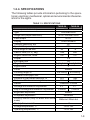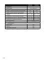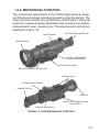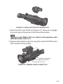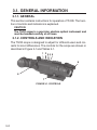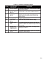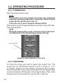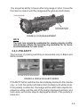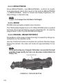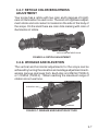
1
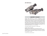
ATN ThOR Series
THERMAL OPTICAL RIFLESCOPES
thor series operator’s manual (Rev. 3, december 2010)
operator’s manual
Important Export Restrictions ! The products,
technologies and services contained in this manual are
subject to one or more export control laws and regulations
of the U.S. Government and they fall under the control
jurisdiction of the US Department of State. It is unlawful
and strictly prohibited to export, or attempt to export or
otherwise transfer or sell any hardware or technical data or
furnish any service to any foreign person, whether abroad or
in the United States, for which a license or written approval
of the U.S. Government is required, without first obtaining
the required license or written approval from the appropriate
Department of the U.S. Government having jurisdiction in
such matters. Diversion contrary to U.S. law is prohibited.
Register your product warranty online at
www.atncorp.com /warranty
The information in this manual furnished for information use only, is subject to
change without notice, is not to be construed as a commitment by ATN Corp.
ATN Corp. assumes no responsibility or liability for any errors or inaccuracies that may appear in this book.
© 2010 ATN Corp. All right reserved.
SAFETY SUMMARY
STUDY CAREFULLY THIS MANUAL BEFORE
TURNING ON AND OPERATING THIS PRODUCT.
CAUTIONS
The ATN ThOR Series Thermal Optical Riflescopes are precision electro-optical instruments and requires careful handling.
To provide safe use of the systems the following instructions
should be observed:
•Do not dismantle the device.
•Keep the device clean; protect it from moisture, sharp temperature drops and shocks.
•Be careful not to touch the glass surfaces. If you put fingerprints on, or contaminate the glass surfaces, use only clean
and soft materials to clean it.
•Do not leave the device in on position during stops in operation.
•Remove the batteries from the device for the period of storage.
Caution :
This product contains natural rubber latex
which may cause allergic reactions
a
WARNING
Do not permanently attach the scope to dynamic-mount applications that continuously transmit vibration (such as on vehicles or heavy machinery).
WARNING
Do not point the scope directly at any high-intensity objects
that you must not view with your eyes (such as the sun or a
welding arc). If you do, you will damage the scope.
WARNING
Operating ThOR Series outside of its specified operating temperature range or voltage range can cause permanent damage
and will void the warranty.
WARNING
Use the power button to turn the scope off before you remove
power (remove batteries or disconnect external power
supply).
WARNING
ThOR Series operates over a wide operating temperature
range (-20°C to +60°C). Not all lithium batteries are specified
over this same temperature span. Check the manufacturer’s
specifications of your selected battery to verify the valid temperature range.
WARNING
Do not use any battery other than a CR-123A lithium battery.
DO NOT use any battery(ies) providing a (combined) voltage
greater than 12.0 volts.
WARNING
Do not install batteries of different types (lithium with lithiumion rechargeable). All batteries must be of the same type.
WARNING
Always replace ALL 4 batteries. If you install new batteries with
used batteries, the result may be dangerous.
b
WARNING
Do not replace batteries in a possibly explosive environment,
such as a gas station (or any place where you must turn off
your vehicle engine). If you do, sparks can cause an explosion.
WARNING
Remove the batteries before you store the riflescopes for
extended periods (2 weeks or more).
WARNING
Do not carry batteries in pockets containing metal objects
such as coins, keys, etc. Metal objects can cause the batteries
to short circuit and become very hot. In the case of lithium batteries, a short circuit could cause them to explode.
WARNING
Observe battery manufacturer’s guidelines for safe handling
and proper disposal of batteries.
eqUipment limitatiOnS
• The ThOR Series detector spectral band (7 to 14 mkm) provides a better penetration through smoke, smog, dust, water
vapor etc.
• Infrared radiation does not travel through glass and therefore
the scope does not sense objects if they are behind a glass
window.
c
TABLE OF CONTENTS
i
pg.
SECTION I. INTRODUCTION
1.1 General Information
1.1.1. Scope
1.1.2.Reports
1.1.3. Storage
1.1.4. Warranty Information
1.2. Description and Data
1.2.1. Description
1.2.2.ThOR Standard Components
1.2.3.ThOR Optional Components
1.2.4. Specifications
1.2.5.Mechanical Functions
1.2.6.Optical Functions
1.2.7. Electrical Functions
1-1
1-2
1-2
1-2
1-2
1-3
1-5
1-5
1-7
1-8
1-8
1-11
1-12
1-12
SECTION II. ASSEMBLY AND PREPARATION
2.1. Preparation
2.1.1.Preparation for Use
2.1.2.Examination for Operation
2.2.Assembly
2.2.1.Remove/installation of
Quick Release Mount (QRM)
2.2.2.Video Output
2.2.3.External Power Source
2.2.4.DVC Installation
2-1
2-2
2-2
2-3
2-4
SECTION III. OPERATION
3.1. General Information
3.1.1. General
3.1.2.Controls and Indication
3.2.Operating procedure
3.2.1. Turning On
3.2.2.Focusing
3-1
3-2
3-2
3-2
3-4
3-5
3-4
2-4
2-5
2-6
2-6
3.2.3.Polarity
3.2.4.Brightness
3.2.5.Zoom
3.2.6.Manual Image Refresh
3.2.7. Reticle Color/Brightness Adjustment
3.2.8.Windage and Elevation
3.2.9. Shut Down Operations
SECTION IV. MAINTENANCE INSTRUCTIONS
4.1. Preventive Maintenance Checks
and Services (PMCS)
4.1.1. Purpose of PMCS
4.1.2. Frequency of Performing PMCS
4.2.Troubleshooting
4.2.1. General
4.2.2.Troubleshooting Procedures
4.3.Maintenance Procedures
4.3.1. Scope Maintenance
4.3.2.Cleaning Procedures
4.3.3.Preparing for Extended Storage
3-5
3-6
3-6
3-6
3-7
3-7
3-8
4-1
4-2
4-2
4-2
4-4
4-4
4-4
4-5
4-5
4-5
4-6
ii
iii
SECTION I
introduction
1-1
1.1 General Information
1.1.1. Scope
This manual contains instructions for use in operating and maintaining the ATN ThOR Series Thermal Optical Riflescopes.
Throughout this manual, the ATN ThOR Series will be referred to
as the scope or ThOR.
1.1.2. Reports
Reports from the user on recommendations for improvements are
encouraged. Send reports to the address below.
American Technologies Network Corp.
1341 San Mateo Avenue
South San Francisco, CA 94080
(800) 910-2862
(650) 989-5100
(650) 875-0129 fax
[email protected]
www.atncorp.com
1.1.3. Storage
Storage of ThOR should be done in the factory packing and after a
thorough PMCS as outlined in Section 4.1 of this manual. This will
ensure the scope remains in mission ready condition during storage. Batteries should be stored separately from the scope.
The scope should not be placed on the floor, in any area exposed
to high temperatures or direct sunlight. Presence of acid and alkaline vapor, as well as of other aggressive admixtures in the air
is unacceptable.
1-2
1.1.4. Warranty Information
One Year Product Warranty
This product is guaranteed to be free from manufacturing defects in material
and workmanship under normal use for a period of 1 (one) year from the date
of purchase. In the event a defect that is covered by the foregoing warranty
occurs during the applicable period stated above, ATN, at its option, will either
repair or replace the product, and such action on the part of ATN shall be the
full extent of ATN’s liability, and the Customer’s sole and exclusive remedy.
This warranty does not cover a product (a) used in other than its normal and
customary manner; (b) subjected to misuse; (c) subjected to alterations, modifications or repairs by the Customer of by any party other than ATN without
prior written consent of ATN; (d) special order or “close-out” merchandise or
merchandise sold “as-is” by either ATN or the ATN dealer; or (e) merchandise
that has been discontinued by the manufacturer and either parts or replacement units are not available due to reasons beyond the control of ATN. ATN
shall not be responsible for any defects or damage that in ATN’s opinion is
a result from the mishandling, abuse, misuse, improper storage or improper
operation, including use in conjunction with equipment which is electrically
or mechanically incompatible with or of inferior quality to the product, as well
as failure to maintain the environmental conditions specified by the manufacturer. This warranty is extended only to the original purchaser. Any breach of
this warranty shall be waived unless the customer notifies ATN at the address
noted below within the applicable warranty period.
The customer understands and agrees that except for the foregoing warranty,
no other warranties written or oral, statutory, expressed or implied, including
any implied warranty of merchantability or fitness for a particular purpose,
shall apply to the product. All such implied warranties are hereby and expressly disclaimed.
Limitation of liability
ATN will not be liable for any claims, actions, suits, proceedings, costs,
expenses, damages or liabilities arising out of the use of this product.
Operation and use of the product are the sole responsibility of the Customer. ATN’s sole undertaking is limited to providing the products and
services outlined herein in accordance with the terms and conditions of
this Agreement. The provision of products sold and services performed
by ATN to the Customer shall not be interpreted, construed, or regarded, either expressly or implied, as being for the benefit of or creating
any obligation toward any third party of legal entity outside ATN and the
Customer; ATN’s obligations under this Agreement extend solely to the
Customer. ATN’s liability hereunder for damages, regardless of the
form or action, shall not exceed the fees or other charges paid to
ATN by the customer or customer’s dealer. ATN shall not, in any
event, be liable for special, indirect, incidental, or consequential
1-3
damages, including, but not limited to, lost income, lost revenue,
or lost profit, whether such damages were foreseeable or not at
the time of purchase, and whether or not such damages arise out
of a breach of warranty, a breach of agreement, negligence, strict
liability or any other theory of liability.
Product warranty registration
In order to validate the warranty on your product, ATN must receive a
completed Product Warranty Registration Card for each unit or complete
warranty registration on our website at www.atncorp.com. Please complete the included form and immediately mail it to our Service Center: ATN
Corporation, 1341 San Mateo Avenue, South San Francisco, CA
94080.
Obtaining warranty service
To obtain warranty service on your unit, End-user must notify ATN service department by calling 800-910-2862 or 650-989-5100 or via e-mail
[email protected] to receive a Return Merchandise Authorization
number (RMA). When returning please take or send the product, postage
paid, with a copy of your sales receipt to our service center, ATN Corporation at the address noted above. All merchandise must be fully insured
with the correct postage; ATN will not be responsible for improper postage or, missing or damaged merchandise during shipment. When sending
product back, please clearly mark the RMA# on the outside of the shipping box. Please include a letter that indicates your RMA#, Name, Return
Address, reason for service return, Contact information such as valid telephone numbers and/or e-mail address and proof of purchases that will help
us to establish the valid start date of the warranty. Product merchandise
returns that do not have an RMA listed may be refused or a significant delay in processing may occur. Estimated Warranty service time is
10-20 business days. End-user/customer is responsible for postage to ATN
for warranty service. ATN will cover return postage/shipping after warranty
repair to end-user/customer only if product is covered by aforementioned
warranty. ATN will return product after warranty service by domestic UPS
ground and/or domestic mail. Any other requested, required or international shipping method the postage/shipping fee will be the responsibility
of the end-user/customer.
1-4
1.2.Description and Data
1.2.1. Description
A. Purpose.
The ThOR Series Thermal Optical Riflescopes combines the ergonomic features of a handheld and the convenience of weapon
mounting. Based on the proven 320 x 240 microbolometer core,
the ThOR is an ideal product for force protection, border patrol
officers, police SWAT and special operations forces providing
them the tools they need to be successful in all field conditions
both day and night. Uncooled thermal imaging cuts through dust,
smoke, fog, haze, and other battlefield obscurants. Its use cannot
be detected as it emits no visible light or RF energy and operates
without the use of illuminators or IR lights.
Figure 1-1. ATN ThOR-2 Thermal Optical Riflescope
Figure 1-2. ATN ThOR-3 Thermal Optical Riflescope
1-5
B. Features.
ThOR has the following important features:
•High resolution digital thermal imaging
•Compact, lightweight and durable housing
•True magnification
•High end OLED display
•Two-colors reticle system
•Rapid start-up in 3 seconds
•Up to 6 hours operation with four lithium batteries
•One-Year Warranty
1-6
1.2.2. ThOR Standard Components
The ThOR standard components are shown in Figure 1-3 and
presented in Table 1-1.
3
1
4
8
2
5
6
7
Figure 1-3. Thor Standard Components
Table 1-1. ThOR Standard Components
ITEM
DESCRIPTION
QTY
1
Scope
1
2
Quick Release Mount
1
3
Hard Storage Case
1
4
Lens Tissue
1
5
Lithium Battery CR123A
4
6
RCA Video/power Adapter
1
7
Operator’s Manual
1
1)
2)
Scope
The thermal imaging scope.
Quick Release Mount
Used to mount scope to weapon.
3) Hard Storage Case
A protective case used for shipping/storing ThOR and
accessories.
1-7
4) Lens Tissue
Uses for cleaning of lenses surface.
5) Lithium Battery CR123A
Four CR123A lithium batteries used to power the unit.
6) RCA Video/power adapter
RCA Video/power adapter used for video transmission
and to connect external power sources.
7) Operators Manual
Provides equipment description, use of operator controls
and preventative maintenance checks and service.
1.2.3. ThOR optional Components
The ThOR optional components are shown in Figure 1-4 and
presented in Table 1-2.
Figure 1-4. Thor Optional Components
Table 1-2. ThOR Optional Components
DESCRIPTION
DVC
QTY
1
1) DVC
DVC - Digital View Clip-on dual day/low-light high-resolution
CCD video camera attachment .
1-8
1.2.4. specificaTIONS
The following tables provide information pertaining to the operational, electrical, mechanical, optical and environmental characteristics for the sights.
Table 1-3. Specifications
ThOR-2x
ThOR-3x
Sensor (microbolometer)
320x240
Type
Uncooled 30hz
Image Size (output resolution)
NTSC: 640x480 30hz Video output
NTSC
Display
OLED 852x600
Thermal Sensitivity, mK
50
Spectral Response, μm
7-14
Focal length of the lens
50
75
Field of View (H x V), deg
12x9
8x6
Angular resolution, mrad
0.6
0.4
Diopter
±5
Eye Relief, mm
45
Magnification
2x (digital 4x) 3x (digital 6x)
Digital Zoom
2
Focus
Manual
Focusing range, m
3 to infinity
5 to infinity
Diameter of exit pupil, mm
10
Distance of the human detection, m
915
1350
Distance of the human recognition, m
450
675
Reticle
Crosshair, 2 colors
Windage and Elevation Adjustment
± 2°
± 1°
Step of Windage and Elevation Adjustment
3/4 MOA
1/2 MOA
Brightness adjustment
Manual
Sharpness adjustment
Automatic
Polarity control (only in Black and White
mode)
Start up time, seconds
Storage temperature, °C
Operating temperature, °C
White hot / Black hot
<3
-50 to +90
-20 to +60
1-9
ThOR-2x
Waterproof
Battery type
Battery Life, h
Weight, g (without bracket, with batteries)
Weight, g (with bracket, with batteries)
Dimensions (L x W x H), mm (without
bracket)
Dimensions, inches (without bracket)
Dimensions (L x W x H), mm (with bracket)
Dimensions, inches (with bracket)
Mounting bracket
External power
Other Options
Video output
Video in
Low Battery Indicator
ThOR-3x
+
4(CR123A)x3V
6
920
1050
1050
1180
215x77x83
260x77x83
8.5x3.0x3.3 10.2x3.0x3.3
215x77x88 260x77x88
8.5x3.0x3.5 10.2x3.0x3.5
Quick Release Picatinny
9 - 12V DC
Yes
Yes
Yes
* ATN reserves the right to change the above specifications at any time without notice
1-10
1.2.5. Mechanical function
The mechanical adjustments of the ThOR sights allow for physical differences between individual operators using the system. The
scope functions include the switchboard, refresh button, universal
connector, eyepiece diopter adjustment ring, focusing ring, battery
compartment cover, mounting rail. The mechanical controls are
identified in Figure 1-5.
SWITCHBOARD
DIOPTER ADJUSTMENT RING
FOCUSING RING
BATTERy COMPARTMENT
COVER with screws
QUICK RELEASE MOUNT
UNIVERSAL CONNECTOR WITH CAP
PICATINNY RAILS
ELEVATION ADJUSTMENT
RUBBER EYE CUP
LENS CAP
RETICLE COLOR/BRIGHTNESS
ADJUSTMENT
WINDAGE ADJUSTMENT
Figure 1-5. ThOR Mechanical Controls
1-11
1.2.6. Optical function
The optical functions include an objective lens, thermal imaging
detector, display and eyepiece. Infrared energy is emitted proportionally to the temperature of an object. The warmer the object, the
more energy it emits. The infrared energy from the objects is focused by the optics, onto an infrared detector. The information from
infrared detector is passed to electronics for image processing. The
signal processing circuitry translates the infrared detector data into
an image that can be viewed on the built-in OLED display. The image is observed through an eyepiece by operator.
1.2.7. electrical function
The electronic circuit is powered by replaceable four 3V lithium batteries (CR123A).
ThOR can be connected to an external 12 VDC/ 2A power supply
using video cable.
Power from the batteries or external power supply is supplied to the
components through the ON/OFF switch button.
1-12
SECTION II
assembly and preparation
2-1
2.1.preparation
2.1.1. Preparation for Use
This chapter contains the information necessary to prepare the
scope for operation. This includes unpacking, examination for damage, and batteries installation.
A. Unpacking.
The following steps must be accomplished prior to each mission
where the sight is used.
1. Open carrying case, remove the scope and check contents for
completeness.
2. Inspect the scope for obvious evidence of damage to optical
surfaces, body, eyecups, operation buttons, etc. Ensure that all
optical surfaces are clean and ready for use. Clean with lens
tissue.
B. Installation of Batteries.
WARNING
The lithium battery contains sulfur dioxide gas under pressure.
Do not heat, puncture, disassemble, short circuit, attempt to
recharge or otherwise tamper with the batteries.
Turn off equipment if battery compartment becomes unduly hot.
If possible, wait until the batteries have cooled before removing
them.
If you inhale sulfur dioxide, seek medical attention.
The ThOR will operate with four CR123A Lithium batteries type.
Install CR123A Lithium batteries as follows.
1. Open the battery compartment cover by unscrewing the screws
counterclockwise.
2. Observe polarity, as indicated on the inside of the battery compartment, and insert four 3.0 Volt CR 123A Lithium batteries into
the battery compartment.
3. Replace compartment cover and screw two fixing screws. Tighten screws firmly to ensure a watertight seal.
2-2
Figure 2-1. Install batteries
2.1.2. examination for operation
Before getting started make sure to follow these steps:
1.Push ON/OFF button on the scope.
2.Make sure that the luminance in ocular is present.
3.Observe the scene, and adjust the diopter and/or lens for optimal image clarity.
2-3
2.2. assembly
2.2.1. Remove/installation of Quick Release
Mount (QRM)
ATN Double Lever Quick Release Mount (QRM) is used for fast
installation/removing the ThOR on MIL-STD-1913/Picatinny rail.
QRM
Mounting
screws
Figure 2-2. Double Lever Quick Release Mount
CLOSED POSITION
A
1
6
2
5
B
4
3
OPENed POSITION
Figure 2-3. Double Lever Quick Release Mount adjustment
1.To remove the QRM from the scope unscrew the two mounting
screws, which attach the QRM to the body of the scope.
2.Mount the QRM onto the scope with two mounting screws.
3.To open the QRM, slide the cam latch (1) forward (arrow A) and
turn the cam (2) backward (arrow B).
4.Your QRM comes with 2 shoes (3). One for standard weaver rails
(designated by the letter W stamped on the shoe) one for MILSTD-1913/Picatinny rail (designated by the letter P stamped on
the shoe). Depending on which rail you are attempting to mount
you must remove the other.
2-4
5.The shoes can also be adjusted for different mounting positions.
To remove shoe unscrew the two screws (4) and place shoe in
desired position.
6.Place the scope onto rail. Be sure to engage the recoil lug into
the groove on the top mounting surface of the rifle.
7.Turn the cam forward pushing the latch to close the mount.
8.The QRM may be adjusted to eliminate excessive play when
mounted on the rail by using the provided wrench (5) to increase/
decrease the cam latch nut (6).
2.2.2. video output
The ThOR incorporates a sealed connector used for video transmission and to connect external power sources. RCA video/power
adapter attaches the scope to the video facilities for video recording
or video transmission (1) to the external display, though at the same
time it accepts the external power supply(2).
Connect the scope to an external video display/recorder and to an
external power supply as follows:
CABLE CONNECTOR
CONNECTOR SOCKET
protective cap
1
2
Figure 2-4. ThOR with Video Cable
1.Remove the batteries.
2.Remove the protective cap from the connector socket.
3.Attach the video cable to the ThOR output connector socket.
4.Attach the RCA plug of the RCA video/power adapter to a compatible jack on an external video display/recorder, or extension
cable.
2-5
2.2.3. external power source
Warning
When the unit is to be powered with external sources, first make
sure the batteries have been taken out.
As an external power source, a standard AC controller with outer
voltage of 12V and current of over 2A can be applied. To connect an
external source recommend to use a 6 mm standard double-pole
socket in the way the positive contact is the central contact.
Use the RCA video/power adapter to connect an external 12V DC/
2A power supply to the ThOR.
Connect an external power supply to the scope as follows:
1.Remove the batteries.
2.Remove the protective cap from the scope output connector
socket.
3.Attach the RCA video/power adapter to the output connector
socket.
4.Attach the power jack socket of the cable to a 12 V DC/ 2 A
power supply.
Notes
1. The external power supply plug must have a 6 mm OD contact with center pin positive.
2. Avoid a sudden removal of power source: use the power
button ON/OFF to turn the scope off before you remove batteries or disconnect external power supply.
3. Replace the protective cap on the scope output connector
socket after disconnecting the cable.
2.2.4. DVC Installation
WARNING!
You are strongly recommended to mount the camera onto the
scope and to adjust it after the scope is adjusted or the weapon
is zeroed to fire with the scope pre-installed on it.
DVC Camera with QRM preinstalled can be mounted onto the Picatinny rail of the ThOR.
2-6
Figure 2-7. Installation onto the atn thor
1.Place the DVC onto ThOR rail (Figure 2-7). Be sure to engage
the recoil lug into the groove on the mounting surface.
NOTE
Operations with QRM of DVC are similar to the operations with
QRM described in Unit 2.2.1.
2. Remove the protective cap from connector socket of ThOR. Insert
DVC connector to the socket.
CABLE CONNECTOR
CONNECTOR SOCKET
protective cap
Figure 2-8. camera cable connection
2-7
2-8
SECTION III
OPERATION
3-1
3.1. General information
3.1.1. General
This section contains instructions for operation of ThOR. The function of controls and indicators is explained.
CAUTION
The ThOR scope is a precision electron-optical instrument and
must be handled carefully at all times.
3.1.2. Controls and indication
The ThOR scope is designed to adjust for different users and corrects for most differences. The controls for the scope are shown or
described in Figure 3-1 and Tables 3-1.
1 2 34
5
8
6
7
Figure 3-1. Controls
3-2
Table 3-1. Controls and Indication
ITEMS
CONTROLS AND
INDICATORS
FUNCTIONS
1
ON/OFF Button
Controls scope power. To turn the unit on and
off press the button .
2
BRIGHTNESS
Buttons
Adjustment of the output image brightness.
3
Polarity
Button
Switch from hot-white/cold-black into hotblack/cold-white mode (only in Black and
White mode).
4
Zoom Button
Digital magnification On.
5
TOUCH UP
Button
Maintains an optimum thermal image.
6
Diopter Adjustment
Focuses eyepiece lens without the need for
glasses. Adjusts for sharper image of intensifier screen.
7
Reticle color/
brightness adjustment knob
Adjusts color (red or green) and brightness
(5 steps) of reticle
8
Objective Lens
Focus
Focuses objective lens. Adjusts for sharpest
image of viewed object.
3-3
3.2.operating procedure
3.2.1. Turning ON
Open the objective lens cover.
NOTE
The objective lens cover protects the scope from inadvertent
exposure to extremely high levels of radiant flux. Never leave the
scope with the objective lens cover off.
To turn the unit on press the button labeled ON/OFF.
After a warm-up time of approximately 3 seconds, video of the thermal scene appears.
NOTE
During the warm-up time, a logo comes into view on the monocular display. Next the thermal image replaces the logo.
ON/OFF button
Figure 3-2. Switchboard of ATN ThOR
3.2.2. FOCUSING
To focus the scope you need to adjust the diopter first. The
scope has an adjustable eyepiece with a range of + 5 to
-5 diopter. Simply turn the diopter clockwise until it stops.
Then concentrate on any object and slowly turn the diopter back
counter clockwise until the grain in the image is sharp. Then rotate
the eyecup to accommodate use over the left or right eye.
3-4
You scope has ability to focus either long range or short. Focus the
front lens to rotate it until the image and the grain are both sharp.
FOCUSING RING
EYEPIECE DIOPTER
ADJUSTMENT RING
Figure 3-3. Focus Adjustment
NOTE
The front lens should be readjusted for viewing objects at different distances. Rotate the focusing ring clockwise for far focus,
counterclockwise for near focus.
3.2.3. Polarity
The function of polarity switching is accessible only in Black and
White models.
Hot-white/cold-black mode
Hot-black/cold white mode
Figure 3-4. Display Polarity Modes
POLARITY button switches the direct display mode into the reverse
one, i.e. from hot-white/cold-black into hot-black/cold-white mode.
If the polarity is white-hot, the image will be with hotter objects displayed as white, and the rest of the image displayed as black, and
vice versa: with hotter objects displayed as black, if the polarity is
black-hot.
3-5
3.2.4. Brightness
Press BRIGHTNESS + and BRIGHTNESS – buttons for brightness adjustment. Each short push of the buttons BRIGHTNESS
+ or BRIGHTNESS – raises or lowers the display brightness, correspondingly, in stepwise way.
NOTE
Levels 1 to 8 range from full dim to full bright.
3.2.5. Zoom
ZOOM button activates a digital zoom function.
The ThOR default digital zoom is 1X. When ZOOM button is pushed
first time, the scope will display a scene magnified 2X. To reset the
magnification to the 1X press ZOOM button again.
3.2.6. MANUAL IMAGE REFRESH
Degradation of the image (image blurring) is caused by charge accumulation on the detector array.
Use the TOUCH UP button to maintain an optimum thermal image.
During this refresh, the video will freeze for approximately 0.5 second.
NOTE
While performing very frequent Refreshes can provide the best
possible image quality but also can decrease substantially the
battery life.
TOUCH UP button
Figure 3-5. TOUCH UP button
3-6
3.2.7. Reticle color/brightness
adjustment
Your scope has a reticle with two color and 5 degrees of brightness of illumination for each color. The knob of brightness adjustment reticle and color select is located on the side of the body of
the scope. On the knob there are color dots marking with color of
illumination of reticle.
Reticle adjustment knob
Figure 3-6. Reticle Adjustment
3.2.8. WINDAGE AND ELEVATION
The vertical and horizontal adjustments for the scope can be
achieved by turning the elevation and windage adjustment mechanisms (remove dust caps first). Each click is 3/4 MOA (ThOR-2)
or 1/2 MOA (ThOR-3) . When reaching the maximum range of
rotation do not use force.
Elevation
Windage
Figure 3-7. Windage and elevation of ThOR
3-7
3.2.9. Shut Down Operations
To finish the work, perform the following:
1.Use the ON/OFF button to turn the scope off.
2.Replace the protective cover on the objective lens.
3.Disconnect the cable (if present). Replace the protective cap on
the scope output connector socket.
4.Return the scope and the cable to the case.
3-8
SECTION IV
maintenance instructions
4-1
4.1. Preventive Maintenance
Checks and Services (PMCS)
4.1.1. Purpose of PMCS
PMCS is performed daily when in use to be sure that the sight is
ready at all times. Procedures listed in Table 4-1 are a systematic
inspection of ThOR that will enable you to discover defects that
might cause the sight to fail on a mission.
4.1.2. Frequency of performing PMCS
The frequency of performing PMCS is as follows:
A.Daily when the sight is in use.
B.When it is removed from the case for any reason.
Table 4-1. Preventive Maintenance Checks and Services
4-2
SEQ.
NO.
ITEM TO
CHECK
1
Completeness
Inventory items by means
of comparing with the data
specified in this manual.
Items missing.
2
Sight Body
Inspect for missing screws
or connector cap.
Screws or connector
cap missing.
3
Front Lens
Cap
Inspect for cuts, tears and
dirt. Clean as required.
Cap torn or cut.
4
Battery
Compartment
Check for corrosion, springs
tension.
Springs corroded or
damaged.
5
Reticle adjustment
knob
Check for operation (without
batteries).
Knob inoperative.
Knob missing.
6
Lenses
Inspect for cleanliness,
scratches, chips or cracks.
Clean as required.
Chipped, cracked or
if scratches hinder
vision through the
sight.
CHECKING PROCEDURE
NOT FULLY MISSION
CAPABLE IF:
SEQ.
NO.
7
8
9
ITEM TO
CHECK
CHECKING PROCEDURE
Objective
Lens
Check to ensure the objective lens is not loose.
Focus
Ring
Check to ensure:
— the focus ring cannot be
moved along the sight body;
— there is free rotation of
the focus ring (more than
3/4 turn).
Rubber
Eye-cup
Inspect for cuts or tears.
NOT FULLY MISSION
CAPABLE IF:
Objective lens loose.
Focus ring able to
move along sight
body.
Focus ring cannot be
rotate.
Rubber Eye-cup torn
or cut.
AFTER CHECKING PROCEDURES
10
Replace protective covers
on the lenses. Remove the
batteries. Return the scope
and all accessories to the
storage case.
4-3
4.2.Troubleshooting
4.2.1. General
This section contains information for locating and removal most of
the ThOR operating troubles which may occur. Each malfunction
for an individual component or assembly is followed by a list of
tests or inspections that will help determine probable causes and
corrective action to take. Perform the tests/inspections and corrective actions in the order listed.
This manual cannot list all possible malfunctions that may occur,
or all tests or inspections and corrective actions. If a malfunction
is not listed (except when malfunction and cause are obvious), or
is not corrected by listed corrective actions, contact to the service
center.
4.2.2. Troubleshooting Procedures
Troubleshooting procedures are listed in Table 4-2.
Table 4-2. Troubleshooting Procedures
4-4
PROBLEM
PROBABLE CAUSE
CORRECTIVE ACTION
Image is absent
Batteries are missing
or improperly installed.
Insert batteries or install correctly.
Batteries are dead.
Replace batteries.
Batteries contact surfaces or contact springs
dirty or corroded.
Clean the contact surfaces
with a pencil eraser and/or
alcohol and cotton swabs.
Cannot achieve
the sharp image
of the object.
Objective and output
lenses dirty.
Clean thoroughly the lenses
surfaces.
Damaged optical components.
Send the sight to the service
center.
The brightness
of the image
on the screen
is low.
The batteries have a
low voltage.
Replace the batteries.
Factory alignment broken.
Send the scope to the service center.
4.3.Maintenance Procedures
4.3.1. Scope Maintenance
The ThOR maintenance consists of external inspection of its components for serviceability, cleaning and installation of the standard and optional accessories. Maintenance instructions covered
elsewhere in this manual (PMCS, troubleshooting, etc.) are not
repeated in this section.
CAUTION
The ThOR is a precision electron-optical instrument and must
be handled carefully at all times to prevent damage.
4.3.2. Cleaning Procedures
A. Cleaning the scope
1.Gently brush off any dirt from the sight body using only a clean
soft cloth.
2.Moisten the cloth with fresh water and gently wipe the external
surfaces (except lenses).
3.Dry any wet surfaces (except lenses) with another dry and
clean soft cloth.
4.Using lens brush, carefully remove all loose dirt from the lenses.
5.Slightly dampen a cotton swab with ethanol and lightly and
slowly wipe the lenses. Clean the glass surfaces by circular
movements from the centre to the edge, not touching the lens
holder and changing cotton swab after each circular stroke.
Repeat this step until the glass surfaces are clean.
B. Cleaning of accessories
Clean accessories with a soft brush (cloth) and soap and water
as required.
CAUTION
Dry thoroughly each item before replacing into the storage
case.
4-5
4.3.3. Preparing for Extended Storage
To prepare the ThOR for extended storage, perform the following:
1.Check the scope for serviceability as outlined in item 4.1 of this
manual.
2.Remove the batteries.
3.Clean the scope and accessories.
4.Replace all items in the case.
4-6
4-7
For customer service and technical support, please contact
American Technologies Network Corp.
North American Office
1341 San Mateo Avenue, South San Francisco, CA 94080
phone: 800-910-2862, 650-989-5100; fax: 650-875-0129
European Office
The following countries can use our toll free number:
00 800 9102-8620
Austria, France, Germany, Holland, Italy, Spain, Sweden, Switzerland
For other countries, please use
38 048-7770214 or 38 048-7770345
www.atncorp.com
©2010 ATN Corporation