1
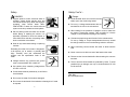
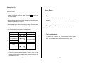
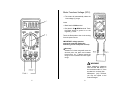
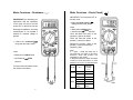
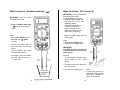
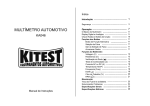
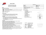
INSTRUCTION
MANUAL
Contents
ATD-5540
AUTOMOTIVE MULTIMETER
INSTRUCTIONS
-1
Safety
1
Meter Basics
4
Meter Functions
4
Voltage(V) …………………………………………………
6
Resistance( Ω )
7
Diode Check(
)
8
Audible Continuity( )
9
DC Current(A)
10
RPM(
)
11
Frequency(Freq)
12
Dwell( )
13
Duty Cycle(%)
14
Maintenance
15
Fuse and Battery Replacement
15
Trouble Shooting
16
General Specifications
16
Electrical Specifications
Warranty Information
17
0
20
Safety Cont ’d…
Safety
DANGER
Danger
Engines produce carbon monoxide which is
odorless, causes slower reaction time, and
can lead to serious injury. When the engine is
operating, keep service areas WELL
VENTILATED or attach the vehicle exhaust
system to the shop exhaust removal system.
Set the parking brake and block the wheels
before testing or repairing the vehicle. It is
especially important to block the wheels on
front-wheel drive vehicles; the parking brake
does not hold the drive wheels.
Wear an eye shield when testing or repair-ing
vehicles.
Exceeding the limits of this meter is dangerous.
lt will expose you to serious or possibly fatal
injury. Carefully read and understand the
cautions and the specification limits of this
meter.
Voltage between any terminal and ground
must not exceed 600V DC or 600V AC.
Use caution when measuring voltage above
25V DC or 25V AC.
Circuit tested must be protected by a 10A fuse or
circuit breaker.
Do not use the meter if it has been damaged.
Avoid electrical shock: do not touch the test
leads, tips or the circuit being tested.
Do not try a voltage measurement with the
test leads in the 10A or the mA terminal.
When testing for the presence of voltage or current, make sure
the meter is functioning correctly. Take a reading of a known
voltage or current before accepting a zero reading.
Choose the proper range and function for the measurement.
Do not try voltage or current measurements that may exceed
the ratings marked on the Function/Range switch or terminal.
When measuring current,connect the meter in series with the
load.
Never connect more than one set of test leads to the meter.
Disconnect the live test lead before disconnecting the common
test lead.
The mA and the 10A terminals are protected by fuses. To avoid
possible injury or damage, use only in circuits limited to DC 10A
for 60 seconds.
See also…
Fuse Replacement
Do not use the test leads if the insulation is damaged or if metal
is exposed.
1
2
Safety Cont’d…
Meter Basics
IMPORTANT
To maintain accuracy of the meter, replace the discharged
battery immediately when the battery symbol
appears on
the meter display.
1. Display:
Large 3 1/2 digit (1999 counts) LCD display with low battery
Avoid measuring error from outside interference: keep the meter
away from spark plug or coil wires.
Avoid damaging the meter when testing voltage: disconnect the
test leads from the test points before changing functions.
Do not exceed the limits shown in the table below:
FUNCTION
Terminal
Input limit
DC Volts
VHzΩ
600 Volts DC
Frequency
①
Ohm(resistance)
500 Volts AC/DC
VHzΩ
Diode
DC 10A
250 Volts AC/DC
10A
*10A AC/DC
VHzΩ
500 Volts AC/DC
indication.
2. Rotary Selector Switch:
Turn this switch to Select a function or turn the meter OFF.
3. Test Lead Terminals:
The Black test is used in the common(COM) terminal for all
rests. The Red test Lead is used to measure Amp or Volts.
RPM
Duty Cycle(%)
Dwell angle
★
10 Amp measurement for 60 seconds maximum.
① Ohms can not be measured if voltage is present, ohms can be
measured only in a non-powered circuit. However, the meter is
protected to 250 volts
3
4
Meter Functions-Voltage (DCV)
The meter will automatically select the
best voltage (V) range.
Insert:
Black lead in COM terminal.
Red lead in V-Ω-RPM terminal Touch
the Black probe to ground or to the
negative (-) circuit.
Touch the Red probe to the circuit coming
from the power source
IMPORTANT: voltage must be
measured in parallel (Red probe
measuring circuit from power source).
Accuracy
Selection of a lower range will move the
decimal point one place and increase
the accuracy. An “I” display means the
range is too low,select the next higher
range.
WARNING
When measuring voltage,be
sure the Red test lead is in
the terminal marked “V”.If the
test lead is in an Amp (A)or
Milliampere (mA) terminal,
you may be injured or the
meter damaged.
5
6
Meter Functions – Resistance (Ω)
IMPORTANT:If you are testing an
application that has capacitors
in the circuit, be sure to turn the
power OFF on the test circuit and
discharge all capacitors. Accurate
measurement is not possible if
external or residual voltage is
present.
Select the resistance( Ω )
range with the rotary switch.
Insert:
Black lead in COM terminal.
Red lead in V-Ω-RPM
terminal.
Touch the test lead probes across
the resistor to be tested.
Meter Functions – Diode Check (
IMPORTANT: Turn the power OFF to
the test circuit
Select the Diode Check (
)
setting with the rotary switch.
Insert:
Black lead in COM terminal.
Red lead in V-Ω-RPM terminal.
Touch the Black test probe to the
negative (-) side of the diode.
Touch the Red test probe to the
positive (+) side of the diode.
Reverse the probes : Black to the
positive (+) side and Red to the
negative (-) side.
Note:
A 〃 good 〃 diode will read low in
one direction and high in the other
direction when the probes are
reversed (or vice versa).
A defective diode will have the same
reading in both directions or read
between 1.0 to 3.0V. in both directions
Diode
Good
Bad
7
.4 to .9V
Reverse
Probes
+ to OL
OL
.4 to .9V
OL
1.0 to
.4 to .9V
OL
.000V
OL
.4 to .9V
OL
.000V
- to +
1.0 to 3.0V
8
)
Meter Functions – Audible Continuity (
)
Meter Functions
DC Current (A)
IMPORTANT : All current measured
flows through the meter.
It is important that you do not:
Measure current greater than
600 Volts AC or DC, with
respect to ground.
Exceed 60 seconds when
measuring continuous
current between 1A-10A.
Allow five minutes for cool
down before continuing.
IMPORTANT: Turn the power
OFF on the test circuit
Select the Audible Continuity
(
) range with the rotary
switch.
Insert:
Select the 10A range with the
rotary switch.
Black lead in COM terminal.
Red lead in V -Ω- RPM
Insert:
Black lead in COM terminal.
Red lead in the 10A terminal
terminal.
Connect one test probe to
each end of the circuit to be
tested.
Circuit complete, the meter
will beep continuously.
Circuit open, there is no beep
and the display shows to
“ I ” (over limit)
IMPORTANT:
Turn OFF all power to the circuit
or disconnect the circuit from the
power source.
Connect:
The Red probe to the side of the
circuit closest to the power
source.
The Black probe to the side of the
circuit to ground.
Turn the power ON and test.
9
Note:
Current
- must always be
measured with the meter
test probes connected in
series, as described.
10
Meter Functions-RPM/x10RPM
Select the RPM range with the
rotary switch.
or
Select the x 10RPM range with
the rotary switch (1,000 to 12,000
RPM). Multiply the displayed
reading times by ten to get actual
RPM.
Insert the inductive pickup
connecting terminal into the
meter.
Ground lead in COM terminal.
Meter Functions-Frequency(Hz)
Select the Frequency(Freq)
setting with the rotary switch.
Set the rotary switch to the
Frequency range that gives the
most accurate measurement
reading.
Insert:
Black lead in COM terminal.
Output lead in V -Ω- RPM
terminal.
Connect the inductive pickup to a
spark plug wire. lf no reading is
received, unhook the clamp, turn it
over and connect again.
Note:
·Position the inductive pick-up as
far away from the distributor and
the exhaust manifold as possible.
· Position the inductive pick-up to
within six inches of the spark plug
or move it to another plug wire if
no reading or an erratic reading is
received.
11
Red lead in V-Ω-RPM
terminal. Connect the
Black test probe to
ground.
Connect the Red test probe
to the ”signal out” wire of the
sensor to be tested.
12
Meter Functions-Dwell
Select the proper Dwell
range with the rotary switch.
Meter Functions-Duty Cycle (%)
Insert:
Select the % Duty Cycle
range with the rotary switch.
·Black lead in COM terminal.
Insert:
·Red lead in V-Ω-RPM terminal.
Connect the Black test probe
to ground.
·Black lead in COM terminal.
·Red lead in V-Ω-RPM terminal.
Connect the Red test probe to the
wire that connects to the breaker
points(see illustration).
Connect the Black test probe to
ground.
Connect the Red test probe to
signal wire circuit.
the
The illustration for a mixture control
solenoid is shown with the metering
rod in the closed position. The
meter will display the percentage of
time the plunger is in the closed
position (low duty cycle) during one
duty cycle.
13
14
Maintenance
Trouble Shooting
Fuse and Battery Replacement
1. Meter wilI not turn ON.
Check the battery contacts for a tight fit.
Check for a minimum battery voltage of 8.0 volts.
WARNING:
Avoid electrical shock: remove test leads before opening
case.
Do not operate the meter or rotate the meter switch when
the case is open.
1. To replace a battery or fuse, loosen the three screws in the case
back and remove the case by lifting up and forward .
2. Replace the battery with an 9 Volt alkaline battery.
Important:
To prevent contamination of the circuits, your hands must
be clean and the printed circuit board must be held by the
edges.
Replace the fuses with the same type of fuse.
10 A is a F 10 A ,250V high energy, fast acting fuse.
Make sure the replacement fuse is centered in the fuse
holder.
3.Re-assemble the case. Fasten the three screws.
2. Ampere reading is erratic or there is no reading at all.
Disassemble the meter back cover and test the fuses for
continuity.
3. Meter reading is erratic.
Printed circuit board contaminated from handling with hands.
Low battery.
Open circuit in a test lead (frayed or broken wire).
Wrong range selected.
“Blown” fuse.
General Specifications
GENERAL SPECIFICATIONS
Display : 3 1/2digit(1999 counts)liquid crystal display(LCD)
Polarity : Automatic,(-)negative polarity indication.
Overrange lndication :“1”
mark indication.
Low Battery lndication: The
is displayed when the battery
voltage drops below the operating
level.
Measurement Rate :2 times per second ,nominal.
Operating Environment : 0℃to 50℃ (320 0F to 122 0F)
15
16
at<70% R.H.
Storage Environment : -20℃to 60℃ (-4 0F to140 0F )
at<80%R.H
Temperature Coefficient : 0.2×(specified
accuracy ) / ℃
( < 18 ℃ or > 28℃ ).
Power : Single standard 9 Volt battery (NEDA 1604 or lEC6F22).
Battery Life : 200 hours typical with alkaline battery.
Fuse : 10A/600V,6.3×25mm fast acting ceramic type.
Dimensions : 147mm(H)×70mm(W)×39mm(D).
Weight : Approx.222g(Meter Only),355g(With Holster).
%DUTY CYCLE
Ranges:1.0%-90.0%
Resolution:0.1%
Pulse width:>100us,<100ms
Accuracy:±(2.0%rdg+5dgts)
Overload protection: 500VDC or RMS AC
DWELL ANGLE
No.of cylinders:3,4,5,6,8
Ranges:0-120.00(3CYL),0-90.00(4CYL),0-72.00(5CYL),
0-60.00(6CYL),0-45.00(8CYL)
Resolution:0.1
Accuracy:±(2.0%rdg+5dgts)
Overload protection: 500VDC or RMS AC
Electrical Specifications
ELECTRICAL SPECIFICATIONS*
Accuracy is given as±([%of reading]+[number of least
significant digits])at 180C to 280C(650F to 830F),with relative
humidity up to 70%.
RPM(Tach)
Ranges:600-2000, 6000-12000(x10RPM)
Resolution:1 RPM
Effect Reading:>600RPM
Accuracy:±(2%rdg+4 dgts)
Overload protection:500VDC or RMS AC
DC VOLTAGE
Ranges : 200mV, 2V, 20V, 200V, 600V
Resolution :100μV
Accuracy :±(0.5%rdg+1dgt)on 200mV
±(0.8%rdg+1dgt) 2V to 600V ranges
Input impedence :10MΩ
Overload protection:600VDC or AC rms.
DC CURRENT
Ranges:10A
Resolution:10mA
Accuracy:±(3.0%rdg+3dgts)
17
18
Input protection:10A/250V fast acting ceramic fuse on 10A input
RESISTANCE
Ranges : 200Ω, 2KΩ, 20KΩ, 2MΩ, 20MΩ
AUDIBLE CONTINUITY
Audible threshold : Less than 50Ω
Resolution:100mΩ
Overload protection:250VDC or RMS AC
Resolution : 100m
Accuracy :±(0.8%rdg+3dgts) on 200Ω
±(0.8%rdg+2dgts) on 2KΩ to 2MΩ ranges
±(1.5%rdg+5dgts) on 20MΩ ranges
Overload protection:250VDC or RMS AC
FREQUENCY
Ranges : 200Hz, 2000Hz, 20KHz
Resolution : 0.1Hz
Accuracy :±(1.0%rdg+4dgts) on all ranges
Sensitivity : 3.5V RMS min. at>20% and <80% duty cycle
Effect Reading : More than 100 digits at pulse width>2μ Sec
Overload protection : 500 VDC or RMS AC
DIODE TEST
Test current : 0.6mA typical(Vf=0.6V)
Resolution :1mV
Accuracy :±(10%rdg+3dgts)
Open circuit voltage : 3.0Vdc typical
Overload protection : 250VDC or RMS AC
Warranty Information
This product is warranted to be free from defects for
one year. If this product fails during the first 12 months
due to faulty materials or workmanship, it will be
replaced free of charge, at the discretion of the
manufacturer.
NOTE: This one year warranty does not cover dead
batteries and blown fuses.
For warranty and service coverage, please return this
product to your dealer for processing and evaluation.
OR, return it directly to:
Electronic Specialties, Inc.
139 Elizabeth Ln.
Genoa City, WI 53128
262-279-1400
WWW.ESITEST.COM
Defective units being returned to your dealer or to the
factory should include proof of purchase date.
Any testers that do not function due to misuse or abuse
will be subject to “out of warranty service charges.”
19
20