1
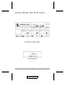
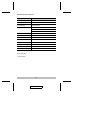
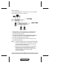
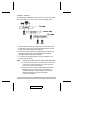
User Manual
CS-102
CS-122
Read this guide thoroughly and follow the installation and operation
procedures carefully in order to prevent any damage to the unit and/or
any devices that connect to it.
This package contains:
M 1 Master View CS-102 or CS-122 KVM Switch
M 1 User Manual
If anything is damaged or missing, contact your dealer.
© Copyright 1995 - 2004 ATEN® International Co., Ltd.
Manual Part No. PAPE-1249-100
Printed in Taiwan 08/2004
All brand names and trademarks are the registered property of their respective owners.
2004-08-18
Note: This equipment has been tested and found to comply
with the limits for a Class B digital device, pursuant to Part
15 of the FCC Rules. These limits are designed to provide
reasonable protection against harmful interference in a
residential installation. This equipment generates, uses and
can radiate radio frequency energy, and if not installed and
used in accordance with the instruction manual, may cause
interference to radio communications. However, there is no
guarantee that interference will not occur in a particular
installation. If this equipment does cause harmful
interference to radio or television reception, which can be
determined by turning the equipment off and on, the user is
encouraged to try to correct the interference by one or more
of the following measures:
M Reorient or relocate the receiving antenna;
M Increase the separation between the equipment and
receiver;
M Connect the equipment into an outlet on a circuit different
from that which the receiver is connected;
M Consult the dealer or an experienced radio/television
technician for help.
2004-08-18
Overview
The CS-102 or CS-122 CPU Switch is a controller for one user
to access multiple computers. Before the development of the
Master View, the only way to control multiple computer
configurations from a single console was through a complex
and costly network system. Now, with a Master View CPU
Switch, you can easily access multiple computers in a cost
effective manner. The CS-102 and CS-122 are basically similar
in their functions. The difference is that the latter offers PS/2
mouse ports.
There are two methods to switch from one computer to the
other: with a pushbutton switch, or with Hot Keys. Setup is fast
and easy; plugging cables into their appropriate ports is all that
is entailed. There is no software to configure or install, and
there are no incompatibility problems. Since the Master View
intercepts keyboard input directly, it works on any hardware
platform and with all operating systems.
A CS-102/CS-122 can control up to two computers. Units can
be cascaded to three levels, allowing the user to control even
more computers. A powerful auto-scan feature scans all
operational computers one by one and stops upon user
requests. The CS-102/CS- 122 CPU Switch is ideal for Server,
Control Room, Testing, etc.
-1-
2004-08-18
Features
M
M
M
M
M
M
M
M
M
CS-102 for PCs / CS-122 for PS/2s.
PS/2 Mouse and MS Mouse Emulation.
Supports SVGA, VGA, and Mutisync Monitors.
Simple Keystrokes or Pushbutton for PC Selection.
Buzzer Sounds for Switching Confirmation.
Three Stage Cascadable.
Power-free Operation.
Auto Scan and Manual Selection.
Caps Lock, Num Lock, Scroll Lock States Automatically
Saved and Restored When Switching Among Computers.
M Scan Mode Automatically Switches Through Powered On
Computers - Scan Rate is DIP Switch Selectable.
M Saves Space, Equipment, and Power Costs.
M Easy Hot Key Control is Compatible With Normal Keyboard
Operation.
-2-
2004-08-18
Front, Rear, and Side Views
CS-102 Front and Rear Panels
CS-122 Side Panel
-3-
2004-08-18
Specifications
Function
Specification
Power Consumption
DC 9V 160mA (max.)
PC Connections
2
PC Selected By
Keyboard/Button
LEDs
1 Power
2 Ready
2 Select
Scan Interval
3, 10, 20, 40 Sec.
Keyboard Connector
5-pin DIN+ / 6-pin mini-DIN*
Mouse Connector
9-pin D Type Male/Female
PS/2 Mouse Connector
6-pin mini-DIN Female*
Monitor Connector
15-pin D Type Female/Male
Enclosure
Plastic and Metal
Weight
1150g
Dimensions (L x W x H)
224 x 152 x 52 (mm)
+ CS-102 only
* CS-122 only
-4-
2004-08-18
Installation
Installation is fast and easy; plugging cables into their
appropriate ports is all that is entailed. A Master View
CS-102/CS-122 unit can control two PCs. To control even more
computers, units can be cascaded to three levels.
CS-102/CS-122 units can also be cascaded down from CS-104
and CS-106 Master View switches.
Single Stage
A Single Stage Installation enables one CS-102 or CS-122 to
control up to two computers, as shown in the diagram, below.
M Set DIP Switch 4 On.
M Connect the monitor output port, mouse port, and keyboard
port of the computer to either of the PC ports on the CPU
SWITCH with appropriate cables.
M 5-pin DIN connectors are for AT style keyboard sockets; 6-pin
mini-DIN connectors are for PS/2 style keyboard sockets.
M Use either port per computer.
M Add a power adapter if the CPU Switch works abnormally.
-5-
2004-08-18
Two Stage
In a two stage installation, the CS-102 or CS-122 is cascaded
down from either a CS-104 or CS-106:
M Set DIP Switch 4 of the first stage unit On; set all others Off.
M Computers may be connected to the first stage and the
second stage CPU Switches.
M 5-pin DIN connectors are for AT style keyboard sockets; 6-pin
mini- DIN connectors are for PS/2 style keyboard sockets.
M Use either keyboard port per computer.
M To connect the keyboard ports of two CPU Switches, use
the 5-pin DIN ports only.
Note: 1. Add a power adapter if the CPU Switch works abnormally.
2. You cannot use the CPU1 or CPU2 ports of a CS-102
or CS-122 to connect back to a CS-104 or CS-106.
You must use the Console ports.
3. PS/2 users must connect a PS/2 mouse, because a
serial mouse can not replace a PS/2 mouse. For
cascaded operation, connect PS/2 mouse ports of
successive stages using a 6-pin mini-DIN
male-to-male cables.
-6-
2004-08-18
Three Stage
In a three stage installation, the CS-102 or CS-122 is cascaded
down from either a CS-104 or CS-106 second stage switch:
M Set DIP switch 4 of the first stage unit On; set all others Off.
M Computers may be connected to the first stage, the second
stage, and the third stage CPU Switches.
M 5-pin DIN connectors are for AT style keyboard sockets; 6-pin
mini-DIN connectors are for PS/2 style keyboard sockets.
M Use either keyboard port per computer.
M To connect the keyboard ports of two CPU Switches, use
the 5-pin DIN ports only.
Note: 1. Add a power adapter if the CPU Switch works abnormally.
2. You cannot use the CPU1 or CPU2 ports of a CS-102
or CS-122 to connect back to a CS-104 or CS-106.
You must use the Console ports.
3. PS/2 users must connect a PS/2 mouse, because a
serial mouse can not replace a PS/2 mouse. For
cascaded operation, connect PS/2 mouse ports of
successive stages using a 6-pin mini-DIN
male-to-male cables.
-7-
2004-08-18
Operation
There are two ways to access any computer on the installation:
by pressing the front panel SELECT BUTTON, or by entering
Hot Keys from the keyboard. Once a computer has been
accessed, the CPU Switch directs keyboard control, mouse
control, and video image of that computer to you as if the
computer were right next to you.
Front Panel Button Selection
To select a computer with this method:
M Simply press the front panel SELECT BUTTON of the CPU
Switch it connects to several times. When it is selected, the
corresponding LED turns on to indicate so.
M For a two stage installation, you have to select with both
CPU Switches; for a three stage installation, you have to
select with all three CPU Switches.
M The SELECT LED turns on when the SELECT BUTTON is
pressed.
Hot Key Selection
Hot Keys are entered by pressing and releasing the Alt, Ctrl,
and Shift keys simultaneously, followed by the command
key(s), and end with pressing the Enter key.
Scan Mode:
Scan Mode automatically scans powered on computers
one-by-one from the first computer of the first stage to the last
computer of the last stage. To start Scan mode, enter this
combination:
[Alt+Ctrl+Shift]+0+[Enter]
To end Scan Mode, press the Spacebar
-8-
2004-08-18
Previous/Next Mode:
Previous/Next Mode selects powered on computers manually
one-by-one from the first computer of the first stage to the last
computer of the last stage. To start Previous/Next mode, enter
this combination:
[Alt+Ctrl+Shift]+9+[Enter]
M To select the previous port, press [Left Shift]
M To select the next port, press [Right Shift]
M To end Previous/Next Mode, press the Spacebar
Direct Port Selection:
With Direct Port Selection you can access any powered on
computer on the installation directly. To directly select a first
stage port, enter this combination:
[Alt+Ctrl+Shift]+#+[Enter]
Where # represents the port number that the computer you
wish to access is attached to.
To directly select a second stage port, enter this combination:
[Alt+Ctrl+Shift]+#+#+[Enter]
Where the first # represents the port number on the first stage
switch that the second stage switch is connected to, and the
second # represents the port number on the second stage
switch that the computer you wish to access is attached to.
-9-
2004-08-18
To directly select a third stage port, enter this combination:
[Alt+Ctrl+Shift]+#+#+#+[Enter]
Where the first # represents the port number on the first stage
switch that the second stage switch is connected to; the second
# represents the port number on the second stage switch that
the third stage switch is connected to; and the third #
represents the port number on the third stage switch that the
computer you wish to access is attached to.
Note: # is a digit between 1 and 6 for a CS-106; 1 and 4 for a
CS-104; and 1 and 2 for a CS-102/CS-122.
Hot Key Summary:
Hot Key functions are summarized in the table, below:
Mode
Results For Correct Hot Keys*
Scan
* Filters out the Hot Keys and beeps once
* Scans powered on computers one by one and flashes
corresponding LED
* Scan rate is set by the DIP switch of the 1st stage unit
* Pressing the Space bar stops this mode
Prev/Next
*
*
*
*
Direct
* Filters out the Hot Keys and beeps once for a ready
port; otherwise, beeps twice
* Switches to the selected port
Filters out the Hot Keys and beeps once
[Right Shift] selects a higher numbered computer
[Left Shift] selects a lower numbered computer
Pressing the Space bar stops this mode
* Inputting incorrect hot keys simply displays the keys.
- 10 -
2004-08-18
Appendix
LEDs
The CS-102/CS-122 contains one Power LED, two Ready
LEDs, and two Port Select LEDs on its front panel. Their
indications are as follows:
LED
Indication
Power LED:
Lights when the CPU Switch is running.
Ready LED:
Lights when the connected PC or CPU Switch is running.
Port Select LED:
Lights to indicate the currently selected port.
Depending on conditions, the Port Select LED turns on and off
according to the following pattern:
Condition
Pattern
1
Port Not Selected
Off
2
Port Connects to a CPU Switch
Flashes Long Off; Short On
3
Port Connects to a Computer
Steady On
4
Port Connects to a Computer
Under Previous/Next Mode
Flashes Long On; Short Off
5
Port Connects to a Computer
Under Scan Mode
Flashes On and Off Equally
- 11 -
2004-08-18
DIP Switch Setting
Scan Time is determined by the DIP Switch of the First Stage*
CPU Switch. For the second and the third-stage CS-102/122
units, all DIP switches are set to Off.
DIP Switch Number
1
2
3
Scan Time
4
ON
ON
X
ON
3 seconds
OFF
ON
X
ON
10 seconds
ON
OFF
X
ON
20 seconds
OFF
OFF
X
ON
40 seconds
* The CPU Switch that the keyboard, monitor, and mouse
connect to is the First Stage unit.
- 12 -
2004-08-18
Troubleshooting
Symptom
Cause
Action
1st stage
Incorrect DIP Switch
CS-102/CS-122 settings.
does not take
Hot Keys.
Set the First Stage unit’s DIP Switch 4
to ON; for all other (cascaded) units,
set DIP Switch 4 to OFF.
Pressing Hot
Keys gets no
response.
CS-102/CS-122 is in
Scan Mode or
Previous/Next Mode.
Press the Spacebar to exit Scan Mode
or Previous/Next Mode.
Selected port
connects to a
powered off computer.
Change the port selection to a
powered on computer.
Improper keyboard
reset.
Unplug the keyboard from the
connector, then plug it back in.
Improper CS-102/122
reset.
Turn off all CS-102s/122s, wait for 5
seconds, then turn them back on.
Turn off all computers, wait for 5
seconds, then turn them back on.
The
CS-102/122
does not work
properly.
The CS-102/122 can
not get enough power
from the computers.
Use a DC 9V power adapter with the
First Stage unit.
- 13 -
2004-08-18
Limited Warranty
IN NO EVENT SHALL THE DIRECT VENDOR’S LIABILITY EXCEED
THE PRICE PAID FOR THE PRODUCT FROM DIRECT, INDIRECT,
SPECIAL, INCIDENTAL, OR CONSEQUENTIAL DAMAGES
RESULTING FROM THE USE OF THE PRODUCT, DISK, OR ITS
DOCUMENTATION.
The direct vendor makes no warranty or representation, expressed,
implied, or statutory with respect to the contents or use of this
documentation, and especially disclaims its quality, performance,
merchantability, or fitness for any particular purpose.
The direct vendor also reserves the right to revise or update the device
or documentation without obligation to notify any individual or entity of
such revisions, or update. For further inquiries, please contact your
direct vendor.
- 14 -
2004-08-18