1
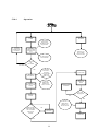
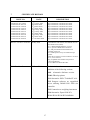
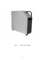
(1918, 2017, 2162, 2176,
2286, 2437, 2536, 2616,
2619, 2650)
III(5)a
Certificate
Pursuant to section 12 of the
Weights and Measures Act 1985
Series V001 Revision 1
Certification No
Valid until
Certification No
Valid until
1918/67 Revision 2
26 September 2015
2437/35 Revision 2
13 January 2014
2017/69 Revision 2
4 September 2016
2536/51 Revision 2
26 October 2016
2162/60 Revision 2
2 September 2011
2616/02 Revision 2
13 January 2014
2176/72 Revision 2
23 March 2014
2619/35 Revision 2
23 March 2014
2286/47 Revision 2
13 January 2014
2650/26 Revision 2
30 December 2012
Authorisation is hereby given by the Secretary of State for Business, Innovation & Skills for the
following Certificates of approval relating to a pattern of a liquid flowmeter to be modified as described
below.
As described in the Certificates below but modified to have an alternative self service device, as detailed
in the descriptive annex, and having the following characteristics:DISPENSER(s):
Dispensers described in certification numbers: 1918, 2017,
2162, 2176, 2286, 2437, 2536, 2616, 2619 and 2650.
SELF SERVICE DEVICE:
Passport Europe’ combined kiosk control and point of sale
system as described in the descriptive annex.
UNATTENDED PAYMENT
TERMINAL
SPOT M3 as described in the descriptive annex
Submitted by:
Gilbarco Veeder-Root Ltd
Crompton Close
Basildon
Essex
SS14 3BA
United Kingdom
Signatory:
for
Reference No: T1118/0026
Date: 29 June 2011
P R Dixon
Chief Executive
National Measurement Office
Department for Business, Innovation & Skills
Stanton Avenue
Teddington
Middlesex, TW11 0JZ
United Kingdom
CONTENTS
1
INTRODUCTION
2
CONSTRUCTION
3
OPERATION
4
INTERLOCKS AND SECURITY FEATURES
5
AUTHORISED ALTERNATIVES
6
RECOMMENDED TESTS
7
CERTIFICATE HISTORY
ILLUSTRATIONS
Figure 1
Figure 2
Figure 3
Figure 4
Figure 5
Figure 6
Figure 7
Figure 8
Figure 9
Figure 10
Figure 11
Figure 12
Figure 13
Figure 14
Figure 15
Figure 16
Figure 17
Figure 18
Figure 19
Figure 20
Figure 21
Figure 22
Figure 23
Figure 24
System Schematic Diagram
Multi POS system with Back Office Computer
Passport Europe Computer
Passport Europe PC External Connection Ports
(later version shown in lower image)
Display / Touchscreen
Data Distribution Module
Customer Display
Receipt Printer
Multifunction Printer
Passport Europe Sales Screen
PDDM
DDM
DDM/PDDM PCB Assembly
Primary Junction Box
Primary Junction Box PCB
Typical IFSF interconnections
Typical Unmanned interconnections
Industrial ruggedised hub
Hub mounted in data interface box
SPOT M2 OPT
SPOT M3‘OPT Pay’
SPOT OPT Side Mounted
SPOT ‘Flexpay’
SPOT outside payment terminal packaging
2
Descriptive Annex
1
INTRODUCTION
Having the dispenser described in the Certification connected to the Gilbarco Veeder-Root
‘Passport Europe’ combined kiosk control unit and point of sale terminal.
The Passport Europe is a combined kiosk control unit and point of sale system with a serial
link to a Data Distribution Module (DDM) that communicates to the dispensers via a current
loop interface. Alternatively the system may have an interface capability to operate via an
IFSF site control protocol.
The system is a PC based unit incorporating an LCD screen with an integral touchscreen.
All Server Point of Sale (POS) mains powered components are supplied via an
uninterruptible power supply (UPS). A schematic diagram of a typical system is shown in
Figure 1.
Multiple POS systems may be connected, and this may include a Back Office unit as shown
in Figure 2. If required, each POS may be powered via a UPS, but it is only a requirement for
the Server POS to be powered via a UPS.
A typical workstation consists of:
Passport Europe Computer Housing
Display / Touchscreen
Magnetic Card Reader
Customer Display
Cash Drawer
Receipt Printer
Uninterruptible Power Supply
Data Distribution Module
Additional equipment
Bar code reader
Multifunction printer
Report printer
Mouse
Keypad
3
2
CONSTRUCTION
2.1
Passport Europe Computer (Figure 3 and 4)
This is the main CPU and support architecture that is PC based. It is housed in a metal
industrial case, which includes a protective cover over the connection ports and an integrated
uninterruptible power supply unit (UPS).
Alternatively the housing may have:
-
additional ventilation louvers
additional ventilation louvers in the front.
It contains the following major components:
2.1.1
Logitron PSPH Internal Power Supply (P/N 50592) - This power supply
provides DC power for the internal logic boards and some of the attached peripherals. It also
provides power for approximately 90 seconds in the event of mains power failure to allow the
PC to power down correctly.
2.1.1.1
alternative.
The power supply ‘PSPE’ with diagnostic LED indicator may be used as an
2.1.2
ASUS Motherboard (Model No: TX97.XE) - A Pentium motherboard
containing processor, memory and peripheral components.
2.1.2.1
The Soltek SL-65LIV-T motherboard may be used as an alternative.
2.1.2.2
The Pentium 4 MB800 Industrial motherboard may be used as an alternative.
2.1.2.3
The Intel Desktop DQ965GF motherboard may be used as an alternative.
2.1.2.4
The motherboard with part number MS6368 may be used as an alternative.
2.1.3
CD/DVD ROM -
A standard PC CD or DVD ROM drive or writer.
2.1.4
Network Board (LAN) - The computer may contain an Ethernet card for
connecting other terminals.
2.1.5
CORE Board - This is a special to type interface card that is used to interface
to the receipt printer, the barcode reader, the customer display and the dispenser interface
(Data Distribution Module). This card would normally only reside in the Server POS
computer.
2.1.6
Modem Board - The computer may contain a modem card to allow remote
diagnostics, credit card authorisation and EFT.
2.1.7
monitor.
Video Board - The computer contains a video card for interfacing to the
4
2.1.8
Hard Drives
The Server computer has 2 hard drives. One is a master and contains the main database
master copy; the other is a slave and contains the working copy of all data. Alternatively the
hard drives may be configured for RAID operation (mirrored) A Client POS computer may
only have one hard drive.
Hard Drives - The Server computer has 2 hard drives. One is a master and contains the main
database master copy; the other is a slave and contains the working copy of all data.
Alternatively the hard drives may be configured for RAID operation (mirrored) A Client POS
computer may only have one hard drive.
2.1.9
Floppy Drive - This is a standard 3.5” floppy disk drive.
2.1.10
Tape backup - The computer may contain a Tape Drive for use when backing
up data contained on the hard drives.
2.2
Operator Display (Figure 5)
This is manufactured by PREH and designated Touch Commander, Model No: MC 12
T3R4W60 bc. It is an LCD flat colour monitor with touch screen interface. This provides the
operator with forecourt status information, transaction data for each fuel dispenser, and gives
a visual display of all the operator commands and instructions and displays retail transaction
data. It is connected to the VGA port and a serial port at the Passport Europe computer.
2.3
Data Distribution Module (Figure 6)
The Data Distribution Module (Model No: BW706028-02) is manufactured by Gilbarco. It
converts the serial data from the Passport Europe computer into a current loop signal for
communication to the fuel dispensers. It is connected to an RS 422 serial port at the Passport
Europe computer.
2.4
Customer Display (Figure 7)
This customer display (Model No: ICD-2002F-B) is manufactured by Puritron Technology
Inc. It is a 40 character two line Vacuum Florescent display and displays the dispenser
number, the price to pay and the sequence number for each fuel transaction selected. It is
connected to an RS 485 serial port at the Passport Europe computer.
2.5
Receipt Printer (Figure 8)
The receipt printer is manufactured by Epson and is designated TM88. It is connected to an
RS 232 serial port at the Passport Europe computer. Alternatively any appropriately CE
marked receipt printer may be connected.
2.6
Multifunction Printer (Figure 9)
This printer is capable of printing receipts, cheques and credit card slips. The printer is
manufactured by Epson and is designated TM-U950 Model No M62UA and is connected to
an RS 232 serial port at the Passport Europe computer. Alternatively any appropriately CE
marked Multifunction printer may be connected.
5
2.7
ISDN Interface
This is a Cisco 761 and is connected to the serial Com port at the Passport Europe computer.
Alternatively any appropriately CE marked ISDN Interface may be connected.
2.8
Cash Drawer
This may be any cash drawer with a solenoid release. It is connected to a to an RS 232 serial
port at the Passport Europe computer.
2.9
Bar Code Reader
This is a Metrologic 6720 and is connected to an RS 232 serial port at the Passport Europe
computer. Alternatively any appropriately CE approved barcode reader may be used.
2.10
Magnetic Card Reader
Any CE approved Magnetic Card Reader may be used. This optionally may be integrated into
the lower Display housing. It is connected to an RS 232 serial port at the Passport Europe
computer.
2.11
Uninterruptible Power Supply (UPS)
Any CE approved UPS that will supply the Primary POS system for a minimum period of 15
minutes.
2.12
IFSF site control protocol
Connection may be made to any suitably configured equipment including fuel dispensers,
payment terminals, forecourt equipment (such as tank gauges) and to ancillary equipment
(such as carwash).
2.12.1
Data Distribution Module and Power and Data Distribution Module
The PDDM (Power and Data and Distribution Module) is shown in Figure 11 and the DDM
(Data Distribution Module) is shown in Figure 12. Each consists of a metal box which houses
power supply unit and an interface card. Model No:BT606981 (Figure 13).
The boxes may vary in size depending on the size and configuration of the forecourt. The
interface card provides IFSF connection from each pump to a LON RJ45 connector at the
Passport Europe computer.
The PDDM has an identical IFSF interface, but contains an additional section for power
distribution.
2.12.2
IFSF Primary Junction Box
The IFSF Primary Junction Box is shown in Figure 14 and consists of a metal box which
houses power supply unit and an interface card. Model No: G1031 (Figure 15). The box may
vary in size depending on the size and configuration of the forecourt. The interface card
provides IFSF connection from each pump to a LON RJ45 connector at the Passport Europe
computer.
6
2.12.3
System
Figure 16 shows a typical example of the system interconnection when Passport is connected
to IFSF pumps using the DDM.
2.12.4
Software Issue
The software version number is 42.36.61.12 and can be displayed by pressing ‘Shift/Day
End’ button and then the ‘About’ button
3
OPERATION
3.1
Dispenser Monitoring
(Figure 10)
The dispenser status is displayed on the pump control icons in the top section of the front
office display. A change in status is reflected in the icon display. A change in status of a
dispenser (e.g. when it is authorised) is shown on every POS.
Details of typical Pump Icons are shown below: -
Free Pump
Pump
Calling
Pump in use
Pump stopped
by the operator
Pump with one
Pump with
outstanding
transaction
pre-paid
credit
Pump with two
3.2
outstanding
Transactions
7
Dispenser Call
When a nozzle is removed from a dispenser, the pump control icon will change to the ‘Pump
Calling’ icon as shown above. To authorise the dispenser the appropriate pump icon is
touched and a new window appears. The Authorise box is then touched to authorise the
pump.
When the nozzle is returned to the dispenser the pump icon will change to either ‘Pump with
one outstanding transaction’ or ‘pump with two outstanding transactions’ as appropriate.
3.3
Stopping the dispensers
To stop a single pump the appropriate pump icon is touched and a new window appears. The
Stop box is then touched to Stop the dispenser. To restart the Resume box is touched. To stop
all of the pumps at the same time, the ‘Stop all’ box on the main screen is touched.
3.4
Normal Sales Operation
Sales operations are identical on each POS.
3.4.1
Follow on transactions
When a nozzle is returned to the dispenser the pump icon will change to ‘Pump with one
outstanding transaction’ as shown above. If the nozzle is removed for a second purchase then
the dispenser may be authorised for the next transaction. Following completion of the
transaction, and providing there is a stored transaction (i.e.: two outstanding transactions), the
dispenser will not be able to be authorised until either the current or the stored transactions
are paid off and cleared.
3.4.2
Clearing for payment
Following a completed delivery the appropriate pump icon is touched. This will open a new
window, which displays any outstanding transactions for that pump. If two sales are present
on the selected dispenser then both amounts will be shown. Pressing the appropriate button
will initiate a sales transaction, and the amount to pay and any other required data will be
shown on the customer display unit. The fuel transaction can be selected at any point of a
sales transaction, and it will be added to that transaction. Fuel sales can also be deleted from
the current transaction and sent back to the pump window for payment at a later time.
Another pump fuel sale can be selected if required. Once the transaction details are correct
the transaction can be paid off by selecting the appropriate payment method and a receipt
printed if required.
It is also possible to have multiple fuel sales on the same transaction and receipt, before the
method of payment is selected.
Dry stock items can be added by either selecting them from the appropriate button on the
display, or by swiping them using the barcode reader.
8
3.5
Method of Payment
When the customer requests to pay by cash and presents the exact money, the operator
touches the CASH button on the display and a receipt can be printed if required. If the
purchaser presents a higher amount than that required, the operator keys in the amount on the
numeric touchpad on the screen.
When the customer requests to pay by CARD, the operator touches the CARD button on the
display.
Other methods of payment, such as cheque, Local account, manual card voucher, can be
registered by touching one of the payment keys on the display. The transaction is completed
and a receipt can be printed if required.
3.6
Pre Payment
Pre payment may be made in the kiosk by cash, cheque, or credit for the amount of fuel
required. Either the POS will print a prepay receipt, or a hand written prepay receipt will be
given to the customer. Fuelling may now begin at the dispenser, which has been pre-paid.
The dispenser will then stop at the cash limit after delivering fuel. On replacing the nozzle if
the customer has taken less fuel than he has paid for, a refund may be obtained at the kiosk. A
full receipt may be printed or hand written at the Point of Sale.
4
INTERLOCKS AND SECURITY FEATURES
4.1
UPS
In the event of any type of mains power failure, the UPS will maintain the Server POS for at
least 15 minutes.
4.2
Duplicate Receipts
Any duplicate receipts are clearly marked with COPY…COPY…COPY…
4.3
Operating System Security
The POS is PC based and runs on the Windows NT Version 4.0 operating system. The only
way to gain access to the operating system is via a password-protected mode of operation,
which is reserved for use by an Engineer.
4.4
Software version
The approved Metrological application software version number is 34.61.20.42 and can be
displayed by touching the ‘About’ button on the front office display. This version relates to
all pump control functions and all other metrological functions that are the subject of this
certificate.
4.4.1
Alternative revised software. Metrological software version number for the
revised software is 32.22.52.66.
4.4.2
Alternative revised software. Metrological software version number for the
9
revised software is 69.94.62.73.
4.4.3
Alternative revised software. Metrological software version number for the
revised software is 32.64.91.59.
4.4.4
Alternative revised software. Metrological software version number for the
revised software is 30.51.80.31.
4.4.5
Alternative revised software. Updated pump driver software so that the price
held in Passport Europe is automatically sent to the dispenser when the dispenser is switched
from stand-alone mode to self-service mode. The functionality described in the certificate
remains the same. The new software version number is 53.92.20.79.
4.4.6
Alternative revised software. The pump driver software has been updated; the
functionality described in the certificate remains the same. The new software version number
is 51.30.40.16.
4.4.7
Alternative revised software to support the SPOT M3 CRIND. Metrological
software version number for the revised software is 22.71.85.03.
4.4.8
Alternative revised software to support the SPOT M3 OPT. Metrological
software version number for the revised software is 25.92.14.86.
4.4.9
Alternative revised software to support the authorised alternatives introduced
in Revision 1. Metrological software version number for the revised software is 31.29.01.53
5
AUTHORISED ALTERNATIVES
5.1
Receipt/Multifunction Printer
Any non-intelligent simple recipient printer that bears the CE mark for conformity to the
EMC Directive 89/336/EEC may be connected. It shall not be capable of transmitting any
data or instructions into the instrument, other than to release the printout or to check for
correct data transmission.
5.2
Management printer
Any CE marked printer may be connected to a workstation for non-trade and management
purposes.
5.2
Modem
A BABT approved and CE marked modem may be connected, using serial communications,
to a serial port on the Passport Europe Computer.
5.3
Operator Display
Any CE marked LCD flatscreen or CRT monitor may be used. The layout and functionality is
the same as described. Where the screen does not have a ‘Touch’ interface a mouse must be
used for making selections on the screen.
10
5.4
Tank Level Gauge
Any CE marked tank level gauge detection system may be connected, using serial
communications, to a serial port on the Passport Europe Computer.
5.5
Price sign
A Pole Sign fuel price display may be connected, using serial communications, to a serial
port on the Passport Europe Computer.
5.6
Car Wash
A Car Wash controller may be connected, using serial communications, to a serial port on the
Passport Europe Computer.
5.7
LPG
Any CE marked LPG Dispenser may be connected, via the Data Distribution Module.
5.8
Payment Terminal
Any CE Marked Indoor Payment Terminal may be connected, using serial communications,
to a serial port on the Passport Europe Computer.
5.8
Loyalty Card Terminal
Any CE Marked Loyalty Card Terminal may be connected, using serial communications, to a
serial port on the Passport Europe Computer.
5.9
Alternative Name
The system may be named ‘PUMA- PRO’ rather than ‘Passport Europe’
5.10
SPOT OPT (Outdoor Payment Terminal)
5.10.1
Terminal Construction
The Secure Payment Outdoor Terminal (SPOT) has two basic component architectures.
M2 (Figure 20)
In this arrangement, the display and pinpad are combined as one physical unit
M3 (Figure 21)
The M3 SPOT terminal is a development of the M2 SPOT terminal, the major change being
separation of the secure pin pad from the display. These are now two physically separate
units connected via secure encrypted communication channel.
The payment terminal accepts bank and fuel cards. The payment terminal has alternatives
described below and is dependent upon a separate forecourt control system for all sequencing
and transaction data.
11
As an alternative to mounting the SPOT into the dispenser (CRIND), it can be mounted
independently on a pedestal to controller customer selected pump. (Figure 22)
The major components used in the SPOT OPT configuration are the same as used for the
SPOT M3 CRIND configuration.
The SPOT OPT operates as the CRIND, but with the added functionality which allows the
customer to select which fuelling point the transaction is to be made from. (Figure 23)
The SPOT can be packaged in a number of different pumps (CRIND) or in a number of
different pedestal configurations (OPT) as shown in figure 24.
The SPOT communication is via TCP/IP using Ethernet CAT5 communication. The
communication is from the Passport network port through a ruggedised Ethernet hub, Figure
18, which is mounted in the CRIND/OPT distribution module, Figure 19. This hub provides
network isolation between forecourt Ethernet network and the kiosk (POS) Ethernet network.
5.10.1.1
RFID interface
An optional I/O device with RF transponder for use with TAG devices of the Radio
Frequency Identification Device (RFID) type. This is typically the Texas Instruments key
fob device. Where installed, the SPOT-CRIND/OPT collects the TAG number and passes it
to the host POS using the same software and hardware systems used for cards.
5.10.1.2
Contact less cards
An optional card interface that communicates to contact less chip cards. Where installed, the
SPOT-CRIND/OPT collects the card information and processes it in an identical manner to
that used in the contact card interface.
5.10.1.3
Journal log
All transactions and system events are recorded in the journal file, one file for each day. A
total of 1 year (365 files) is stored after which the oldest is overwritten. The files are copied
to a second partition as additional backup, and the data integrity is further ensured by storage
on a mirrored RAID array. These journals can be accessed remotely. The journal is not
editable and can be viewed only by site manager using his management login credentials.
There is no site access to the journal outside the Passport application.
5.10.1.4
Journal printer
Having any CE approved printer connected to the Passport Europe as an additional
transaction storage device.
5.10.1.5
Receipt printer
Any receipt printer that bears the CE mark for conformity to the EMC Directive may be used.
12
5.10.2
Interlocks and Security Features
5.10.2.1
Paper insufficient to print receipt
The SPOT CRIND/OPT terminal printer detects when the printer paper is low and displays a
message warning the customer that a receipt is not available but allows further transactions to
commence.
Alternatively, the system can be configured to prevent any new CRIND/OPT transactions
starting once paper low has been detected.
The SPOT CRIND/OPT can be configured to print receipts automatically or on demand
5.10.2.2
Printer fault
If the terminal identifies a printer fault, a message states that the receipt is unavailable but
gives the customer the choice to proceed with transaction.
5.10.2.3
Power Loss
In the event of a power failure in unmanned configuration, the transaction details are
memorised and completed when the power is restored.
5.10.2.4
Duplicate receipts
Duplicate receipts are not available. A receipt can be printed only once.
5.10.3
Printed information
The following information is printed.
Receipt:
Address of the station
Receipt number
Date and Time
Transaction volume, price to pay and pump number
13
5.10.4
Operation
INSERTS
CARD
REMOVE
NOZZLE
IF APPLICABLE
MILEAGE &
REGISTRATION
REQUESTED
CHOOSE
ANOTHER
METHOD OF
PAYMENT
SYSTEM
CHECKS CARD
& SENDS FOR
OLA
PROCESS AS
PAY IN SHOP
TRANSACTION
IF APPLICABLE
PIN ENTERED
CARD OK
OR
DECLINED
DECLINED
OK
RECEIPT
REQUIRED?
BEGIN
FUELLING MAX
£XXXX
IF RECEIPT
PAPER OUT,
“RECEIPT
UNAVAILABLE”
MESSAGE
DISPLAYED
FOR OPT
OPERATION,
PROMPT TO
SELECT PUMP
STOP PUMP
REPLACE
NOZZLE IN
PUMP
TRANSACTION
COMPLETE
REMOVE
NOZZLE
NO
RECEIPT
REQUESTED
?
YES
FOR OPT
OPERATION,
PROMPT TO
SELECT PUMP
PRESET LIMIT
BEEN REACHED
OR CUSTOMER
REPLACED
NOZZLE
PRINT RECEIPT
NO
CONTINUE
FUELLING
TRANSACTION
COMPLETE
YES
14
5.11
ALTENATIVE POS PC TOSHIBA ST-A10
As described in the certificate but having the alternative POS PC designated TEC ST A-10
manufactured by Toshiba. The PC may have any peripheral equipment connected identified in
the certificate.
5.12
PASSPORT SOFTWARE ON RUGGADISED SERVER UTILISING
DOMS PSS 5000 SITE CONTROLLER
5.12.1
Introduction
The PASSPORT system is as described in the certificate but the Passport Europe Computer
assembly is replaced with a Ruggadised PC, Intercomp model CNPEUROPE_10_01 and the
DOMS PSS 5000 site controller.
5.12.2
Forecourt controller DOMS
The DOMS PSS 5000 forecourt controller comprises a metal rectangular box housing the
following main components.
•
•
•
5.12.3
A power supply
A Central Processing Board (CPU) with 8 serial ports (CPB508):
this has an LCD 16x2 character alphanumerical display and a keyboard comprising 5
keys for navigating the menu options.
Hardware interface modules:
dispensers are connected to the CPU board via an appropriate hardware interface
module compatible with the communication protocol of the dispenser.
DOMS Software
The DOMS PSS 5000 has a legal authority module (LAM) for the UK containing specific
parameter values and functions. Reference to the PSS 5000 software version number is not
normally required, but may be accessed as follows: typical LAM version number is 498-06100 and 0D6C for the checksum number. These can be viewed by selecting the appropriate
menu heading using the operator keys on the CPU. The LAM version number and checksum
are accessed as follows:
When the PSS is powered on, the first line displays the application software version and the
current time. The second line displays the W&M Service menu. Pressing the Down Arrow
once, displays the W & M menu, which comprises 7 sub-menus, W.1 to W.7. Press the right
button once to obtain W.1 – LAM INFO and press again to display Version and Checksum
information.
5.13
CONNECTION TO WEIGHING INSTRUMENT
Any non-automatic weighing instrument issued with an EC type-approval certificate by a
Notified Body for type approval under Directive 2009/23/EC in any Member State may be
connected to the server/POS PC. The software controlling the operation of the weighing
instrument is described in EC Test Certificate GB-1398.
15
5.14
ALTERNATIVE EPSON POS PCS IR300/IR310/IR320/IR700/MR800
As described in the certificate but having the alternative POS PC designated IR300, or IR310
or IR320 or IR700 or MR800 manufactured by Epson. The PC may have any peripheral
equipment connected identified in the certificate.
6
RECOMMENDED TESTS
The following tests may be carried out in addition to those specified in the Regulations to
determine conformity to the approved pattern.
6.1
Software Verification
Check that the correct metrological software version number, as detailed in section 4.4, is
installed on each Passport Europe Computer. This can be displayed by touching the ‘About’
button on the computer display.
6.2
System Features
6.2.1
progress.
Check that unit price changes at the dispenser are inhibited when sales are in
6.2.2
Check that the memorised transactions are correct and that it is not possible to
release the dispenser to a third purchaser.
6.2.3
Check that when mains power is removed from the system, the Server Point of
Sale is operational for a minimum of 15 minutes to allow unpaid transactions to be paid off.
6.3
Prepay
Check that when the prepay method of operation is used that:
(i)
The Fuel Dispensers are fitted with 2 stage pre-set solenoid valves
(ii)
The Fuel Dispenser stops at exactly the PREPAY cash value.
(iii)
A notice is displayed advising purchasers using the prepay facility to take a
prepay receipt for the amount prepaid.
(iv)
The volume pre-set function is disabled.
16
7
CERTIFICATE HISTORY
ISSUE NO.
DATE
DESCRIPTION
Certification No 1918/67
Certification No 2017/69
Certification No 2162/60
Certification No 2176/72
Certification No 2286/47
Certification No 2437/35
Certification No 2536/51
Certification No 2616/02
Certification No 2619/35
Certification No 2650/26
14th January 2004
24th March 2004
6th October 2000
24th March 2004
14th January 2004
14th January 2004
24th March 2004
14th January 2004
24th March 2004
31st December 2002
Type examination certificate first issued.
Type examination certificate first issued.
Type examination certificate first issued.
Type examination certificate first issued.
Type examination certificate first issued.
Type examination certificate first issued.
Type examination certificate first issued.
Type examination certificate first issued.
Type examination certificate first issued.
Type examination certificate first issued.
Revision 1 of above certificates
8th May 2009
- Amendments and variants consolidated into one
document Series (V001).
- 2.1.3 added DVD ROM drive or writer
- 2.1.8, option of RAID mirrored drives
- 2.3, UK part number for distribution box
(instead of US one)
- 2.5 Added option of any CE marked receipt
printer
- Alternative software version numbers in sections
4.4.3, 4.4.4 and 4.4.5
- Fig 4 Updated serial channel I/F picture to
current production
- 5.10 Addition of SPOT M3 OPT
V001 Revision 2
29 June 2011
Revision 1 issued:
Addition of the following sections
4.4.9
Alternative Software version
5.10.1.5 Receipt printer
5.11 Alternative PS PC Toshiba ST-A10
5.12 Passport software on ruggadised
server utilising DOMS PSS 5000 site
controller
5.13 Connection to weighing instrument
5.14 Alternative Epson POS PCs
IR300/IR310/IR320/IR700/MR800
17
Figure 1
System Schematic Diagram
18
Figure 2
Multi POS system with Back Office Computer
19
Figure 3
Passport Europe Computer
20
Figure 4
Passport Europe PC External Connection Ports
(later version shown in lower image)
21
Figure 5 Display / Touchscreen
Figure 6
Data Distribution Module
22
Figure 7
Customer Display
Figure 8
Receipt Printer
Figure 9
Multifunction Printer
23
Figure 10
Passport Europe Sales Screen
24
Figure 11
PDDM
Figure 13
Figure 14
Figure 12
DDM
DDM/PDDM PCB Assembly
Primary Junction Box
Figure 15
25
Primary Junction Box
PCB
Figure 16
Typical IFSF interconnections
26
Figure 17
Typical Unmanned interconnections
27
Figure 18
Figure 19
Industrial ruggedised hub
Hub mounted in data interface box
28
Figure 20
Figure 22
SPOT M2 OPT
Figure 21
SPOT OPT Side Mounted
SPOT M3‘OPT Pay’
Figure 23
29
SPOT ‘Flexpay’
SPOT-CRIND fitted to an Enterprise
Pump (M2 or M3)
SPOT-CRIND fitted to an Encore 510
Pump (M2 or M3)
SPOT-CRIND fitted to a SK700 Pump
(M2 or M3)
SPOT-CRIND fitted to a Encore 500G
Pump (M3)
SPOT-CRIND fitted to a Euroline Pump(M2 or M3)
Figure 24
SPOT outside payment terminal packaging
© Crown copyright 2011. This material may be freely reproduced except for sale
30