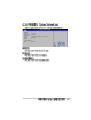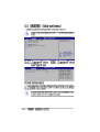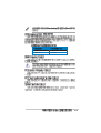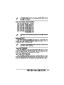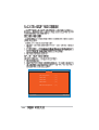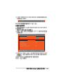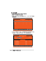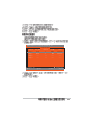
1
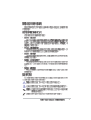
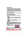
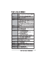
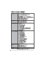
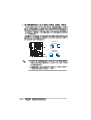
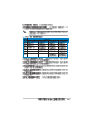
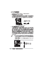
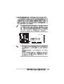
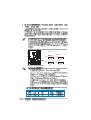
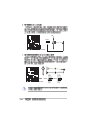
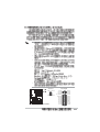
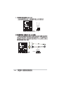
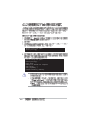
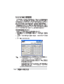
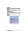
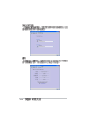
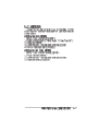
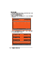
Motherboard
P5GDC-V
DELUXE
T1688
© 2004
2
3
4
5
•
•
•
•
•
•
•
•
•
•
•
•
6
•
•
•
•
•
7
2 3
1 2
Jumper Free
(Default)
Jumper Mode
P5GDC-V Deluxe -TAYZ
6
10839 11036
11XX11XX11
8
0
9
10
1-1
®
®
®
®
®
®
®
®
1-2
®
®
1-3
®
®
1-4
1-5
®
®
®
1-6
®
P5GDC-V
SB_PWR1
P5GDC-VOnboard LED
ON
Standby
Power
OFF
Powered
Off
2-1
P5GDC-V
2-2
2-3
24.5cm (9.6in)
KBPWR1
ATX12V
SPDIF_O1
LGA775
SPDIF_O2
CPU_FAN1
USBPW34
USBPW12
VGA
30.5cm (12.0in)
PWR_FAN1
P5GDC-V
CHA_FAN2
AAFP
USB56
SATA3
SATA4
SATA1
SATA2
USB78
CLRTC1
TSB43AB22A
USBPW56
USBPW78
SB_PWR1
GAME1
CD
SPDIF
COM1
2-4
IE1394_2
CHASSIS1
CHA_FAN1
PANEL1
2-5
2-6
•
•
•
P5GDC-V
P5GDC-V CPU Socket 775
2-7
A
B
2-8
A
B
2-9
•
•
•
•
2-10
2-11
P5GDC-V
2-12
GND
CPU FAN PWR
CPU FAN IN
CPU FAN PWM
CPU_FAN1
DDR_B1
DDR_B2
P5GDC-V DIMM sockets
DDR2_B1
DDR2_A1
P5GDC-V
DDR_A2
DDR_A1
•
•
•
2-13
2-14
2-15
2-16
2-17
2
1
1
2
1
1
2-18
2
3
1
•
•
2
1
1
2-19
2-20
A
B
C
D
E
F
G
H
2-21
2-22
P5GDC-V
CLRTC1
1 2
P5GDC-V Clear RTC RAM
Normal
(Default)
2 3
Clear CMOS
2-23
USBPW12
USBPW34
3
2
2
1
+5V
(Default)
+5VSB
P5GDC-V
USBPW56
USBPW78
1 2
P5GDC-V USB device wake-up
2-24
+5V
(Default)
2 3
+5VSB
KBPWR1
1 2
+5V
2 3
+5VSB
(Default)
P5GDC-V
P5GDC-V Keyboard power setting
2-25
1
2
3
4
5
6
7
8
9
16
2-26
15
14
13
12
11
10
2-27
P5GDC-V
FLOPPY1
P5GDC-V Floppy disk drive connector
•
•
PIN 1
PRI_IDE1
P5GDC-V
P5GDC-V IDE connector
2-28
PIN 1
SEC_RAID1
P5GDC-V
PRI_RAID1
PIN 1
P5GDC-V RAID connectors
•
•
•
2-29
P5GDC-V SATA connectors
•
•
•
•
•
2-30
SATA1
®
GND
RSATA_TXP4
RSATA_TXN4
GND
RSATA_RXP4
RSATA_RXN4
GND
GND
RSATA_TXP3
RSATA_TXN3
GND
RSATA_RXP3
RSATA_RXN3
GND
SATA3
GND
RSATA_TXP2
RSATA_TXN2
GND
RSATA_RXP2
RSATA_RXN2
GND
GND
RSATA_TXP1
RSATA_TXN1
GND
RSATA_RXP1
RSATA_RXN1
GND
P5GDC-V
SATA4
SATA2
GND
CPU FAN PWR
CPU FAN IN
CPU FAN PWM
CPU_FAN1
PWR_FAN1
P5GDC-V
Rotation
+12V
GND
CHA_FAN2
Rotation
+12V
GND
CHA_FAN1
P5GDC-V Fan connectors
Rotation
+12V
GND
2-31
P5GDC-V USB 2.0 connectors
2-32
USB56
1
1
USB+5V
USB_P7USB_P7+
GND
USB+5V
USB_P8USB_P8+
GND
NC
USB+5V
USB_P6USB_P6+
GND
NC
P5GDC-V
USB+5V
USB_P5USB_P5+
GND
COM1
P5GDC-V
PIN 1
P5GDC-V Serial port connector
USB78
•
•
•
•
•
®
®
•
ATX12V1
GND +12V DC
GND +12V DC
P5GDC-V
P5GDC-V ATX power connectors
EATXPWR
+3 Volts
+12 Volts
+12 Volts
+5V Standby
Power OK
Ground
+5 Volts
Ground
+5 Volts
Ground
+3 Volts
+3 Volts
Ground
+5 Volts
+5 Volts
+5 Volts
-5 Volts
Ground
Ground
Ground
PSON#
Ground
-12 Volts
+3 Volts
2-33
+5V
J2B1
J2CX
MIDI_OUT
J2CY
J2B2
MIDI_IN
P5GDC-V CD audio connector
P5GDC-V GAME connector
2-34
+5V
J1B1
J1CX
GND
GND
J1CY
J1B2
+5V
Right Audio Channel
Ground
Ground
Left Audio Channel
P5GDC-V
CD
P5GDC-V
GAME1
Chassis Signal
GND
P5GDC-V
+5VSB_MB
CHASSIS1
(Default)
P5GDC-V Chassis intrusion connector
2-35
P5GDC-V IEEE 1394 connector
2-36
GND
+12V
TPB2GND
TPA2+12V
TPB2+
GND
TPA2+
MIC2
MICPWR
Line out_R
NC
Line out_L
PORT1 L
PORT1 R
PORT2 R
SENSE_SEND
PORT2 L
P5GDC-V Analog front panel connector
•
•
P5GDC-V
IE1394_2
1
NC
AGND
NC
NC
SENSE2_RETUR
GND
PRESENCE#
SENSE1_RETUR
P5GDC-V
AAFP
+5V
Ground
Ground
Speaker
SPEAKER
IDE_LED
Reset
Ground
PWR
Ground
PANEL1
IDE_LED+
IDE_LED-
P5GDC-V
PLED-
PLED+
PLED
Reset
PWRSW
P5GDC-V System panel connector
•
•
•
•
•
2-37
2-38
3-1
3-2
4-1
EZFlash starting BIOS update
Checking for floppy...
EZFlash starting BIOS update
Checking for floppy...
Floppy found!
Reading file “P5GDCVD.rom”. Completed.
Start erasing.......|
Start programming...|
Flashed successfully. Rebooting.
•
•
4-2
•
•
A:\>afudos /oOLDBIOS1.ROM
A:\>afudos /oOLDBIOS1.ROM
AMI Firmware Update Utility - Version 1.10
Copyright (C) 2002 American Megatrends, Inc. All rights reserved.
Reading flash ..... done
Write to file ...ok
A:\>
4-3
A:\>afudos /iP5GDCVD.ROM
A:\>afudos /iP5GDCVD.ROM
AMI Firmware Update Utility - Version 1.19(ASUS V2.07(03.11.24BB))
Copyright (C) 2003 American Megatrends, Inc. All rights reserved.
WARNING!! Do not turn off power during flash BIOS
Reading file ..... done
Reading flash .... done
Search
bootblock version:
123456789012345678901234
0% 123456789012345678901234
123456789012345678901234100%
Advance Check........
Erasing flash .... done
Writing flash .... 0x0008CC00 (9%)
4-4
A:\>afudos /iP5GDCVD.ROM
AMI Firmware Update Utility - Version 1.19(ASUS V2.07(03.11.24BB))
Copyright (C) 2003 American Megatrends, Inc. All rights reserved.
WARNING!! Do not turn off power during flash BIOS
Reading file ..... done
Reading flash .... done
Search
bootblock version:
123456789012345678901234
123456789012345678901234
0%123456789012345678901234100%
Advance Check.........
Erasing flash ..... done
Writing flash ..... done
Verifying flash ... done
Please restart your computer
A:\>
Bad BIOS checksum. Starting BIOS recovery...
Checking for floppy...
4-5
Bad BIOS checksum. Starting BIOS recovery...
Checking for floppy...
Floppy found!
Reading file “P5GDCVD.ROM”. Completed.
Start flashing...
Bad BIOS checksum. Starting BIOS recovery...
Checking for floppy...
Bad BIOS checksum. Starting BIOS recovery...
Checking for floppy...
Floppy not found!
Checking for CD-ROM...
CD-ROM found!
Reading file “P5GDCVD.ROM”. Completed.
Start flashing...
4-6
4-7
4-8
4-9
•
•
•
4-10
System Time
System Date
Legacy Diskette A
Primary IDE Master
Primary IDE Slave
Third IDE Master
Third IDE Slave
Fourth IDE Master
Fourth IDE Slave
IDE Configuration
:
:
:
:
:
:
[11:51:19]
[Mon,06/14/2004]
[1.44M, 3.5 in]
Use [ENTER], [TAB] or
[SHIFT-TAB] to select
a field.
[ST320413A]
[Pioneer CD-ROM ATA]
[Not Detected]
[Not Detected]
[Not Detected]
[Not Detected]
Use [+] or [-] to
configure the System
time.
System Information
4-11
System Time
System Date
Legacy Diskette A
Primary IDE Master
Primary IDE Slave
Third IDE Master
Third IDE Slave
Fourth IDE Master
Fourth IDE Slave
IDE Configuration
[11:51:19]
[Thu 06/10/2004]
[1.44M, 3.5 in]
:[ST320413A]
:[Pioneer CD-ROM ATA]
:[Not Detected]
:[Not Detected]
:[Not Detected]
:[Not Detected]
System Information
Advanced PCI/PnP Settings
WARNING: Setting wrong values in
below sections may cause system to
malfunction.
Plug And Play O/S
PCI Latency Timer
Allocate IRQ to PCI VGA
Palette Snooping
PCI IDE BusMaster
4-12
[No]
[64]
[Yes]
[Disabled]
[Enabled]
System Time
System Date
Diskette A
Primary IDE Master
Primary IDE Slave
Third IDE Master
Third IDE Slave
Fourth IDE Master
Fourth IDE Slave
IDE Configuration
:
:
:
:
:
:
[11:51:19]
[Mon,06/14/2004] Legacy
[1.44M, 3.5 in]
Use [ENTER], [TAB] or
[SHIFT-TAB] to select
a field.
[ST320413A]
[Pioneer CD-ROM ATA]
[Not Detected]
[Not Detected]
[Not Detected]
[Not Detected]
Use [+] or [-] to
configure the System
time.
System Information
4-13
Primary IDE Master
System Time
System Date
Vendor
Size
LBA Mode
Block Mode
PIO Mode
Async DMA
Ultra DMA
SMART Monitoring
:
:
:
:
:
:
:
:
:
:
[11:51:19]
[Mon,06/14/2004]
ST320413A
20.0GB
Supported
16 Sectors
4
MultiWord DMA-2
Ultra DMA-5
Supported
Type
[Auto]
LBA/Large Mode
[Auto]
Block(Multi-sector Transfer) M [Auto]
PIO Mode
[Auto]
DMA Mode
[Auto]
Smart Monitoring
[Auto]
32Bit Data Transfer
[Disabled]
4-14
Select the type of
device connected to
the system.
IDE Configuration
Configure SATA As
Onboard IDE Operate Mode
Enhanced Mode Support On
[Standard IDE]
[Enhanced Mode]
[S ATA mode]
IDE Detect Time Out (Sec)
[35]
When in AHCI/RAID
mode, SATA controller
is forced to Native
mode.
4-15
4-16
AMIBIOS
Version
: 08.00.10
Build Date : 06/18/04
Processor
Type
Speed
Count
: Genuine Intel(R) CPU 3.20 GHz
: 3200 MHz
: 1
System Memory
Size
: 248 MB
4-17
Adjust system
frequency/voltage
JumperFree Configuration
LAN Cable Status
USB Configuration
CPU Configuration
Chipset
Onboard Devices Configuration
PCI PnP
Configure System Frequency/Voltage
AI Overclocking
4-18
[Auto]
Select the target CPU
frequency, and the
relevant parameters
will be auto-adjusted.
Frequencies higher
than CPU manufacturer
recommends are not
guaranteed to be
stable. If the system
becomes unstable,
return to the default.
FSB 800
200 MHz
FSB 533
133 MHz
4-19
4-20
4-21
POST Check LAN cable
LAN Cable Status
Pair
Status
Length
1-2
3-6
4-5
7-8
0.0M
0.0M
0.0M
0.0M
Open
Open
Open
Open
[Disabled]
Enables USB host
controllers.
USB Configuration
Module Version - 2.23.2-9.4
USB Devices Enabled: None
USB Function
Legacy USB Support
USB 2.0 Controller
USB 2.0 Controller Mode
4-22
Check LAN cable
during POST.
[Enabled]
[Auto]
[Disabled]
[HiSpeed]
Configure advanced CPU Settings
Manufacturer : Intel
Brand String : G
Frequency
: 3200 MHz
FSB Speed
: 800 MHz
Cache L1
: 16 KB
Cache L2
: 1024 KB
Cache L3
: 0 KB
Ratio Status: Unlocked
Ratio Actual Value : 16
Ratio CMOS Setting:
VID CMOS Setting:
Microcode Updating:
Max CPUID Value Limit:
Enhanced C1 Control
CPU Internal Thermal Control
Hyper Threading Technology
Sets the ratio between
CPU Core Clock and the
FSB Frequency.
NOTE: If an invalid
ratio is set in CMOS
then actual and
setpoint values may
differ.
[ 8]
[ 62]
[Enabled]
[Disabled]
[Auto]
[Auto]
[Enabled]
4-23
4-24
Advanced Chipset Settings
Configure DRAM Timing by SPD
Hyper Path 2
[Enabled]
[Auto]
Graphic Adapter Priority
Internal Graphics Mode Select
Fixed Graphic Memory Size
DVMT Graphic Memory Size
[PCI Express/Int-VGA]
[Enabled, 8 MB]
[32 MB]
[32 MB]
PEG Buffer Length
Link Latency
PEG Root Control
Slot Power
[Auto]
[Auto]
[Auto]
[Auto]
Enable or disable
DRAM timing.
4-25
4-26
Configure Win627EHF Super IO Chipset
Azalia Controller
Front Panel Support Type
Onboard 1394 Controller
Onboard LAN
LAN Option ROM
ITE8212F Controller
Detecting Device Time
[Enabled]
[AC97]
[Enabled]
[Enabled]
[Disabled]
[IDE Mode]
[Quick Mode]
Serial Port1 Address
Parallel Port Address
Parallel Port Mode
ECP Mode DMA Channel
Parallel Port IRQ
Onboard Game/MIDI Port
[3F8/IRQ4]
[378]
[ECP]
[DMA3]
[IRQ7]
[Disabled]
Enable or disable the
Azalia controller.
®
4-27
4-28
Advanced PCI/PnP Settings
WARNING: Setting wrong values in below sections
may cause system to malfunction.
Plug And Play O/S
PCI Latency Timer
Allocate IRQ to PCI VGA
Palette Snooping
PCI IDE BusMaster
[No]
[64]
[Yes]
[Disabled]
[Enabled]
IRQ-3 assigned to
IRQ-4 assigned to
IRQ-5 assigned to
IRQ-7 assigned to
IRQ-9 assigned to
IRQ-10 assigned to
IRQ-11 assigned to
IRQ-14 assigned to
IRQ-15 assigned to
[PCI
[PCI
[PCI
[PCI
[PCI
[PCI
[PCI
[PCI
[PCI
Device]
Device]
Device]
Device]
Device]
Device]
Device]
Device]
Device]
No: Lets the BIOS
configure all the
devices in the system.
Yes: Lets the
operating system
configure Plug and
Play (PnP) devices not
required for boot if
your system has a Plug
and Play operating
system.
4-29
Suspend Mode
ACPI 2.0 Support
ACPI APIC Support
APM Configuration
Hardware Monitor
4-30
[S1 (POS) only]
[No]
[Enabled]
Select the ACPI state
used for System
Suspend.
APM Configuration
Power Button Mode
[On/Off]
Go into On/Off or
Suspend when Power
button is pressed.
Restore on AC Power Loss
[Power Off]
Power On By RTC Alarm
[Disabled]
Power On By External Modems
[Disabled]
Power On By PCI Devices
[Disabled]
Power On By PS/2 Keyboard
[Disabled]
Keyboard Wakeup Password : Not Installed
Power On By PS/2 Mouse
[Disabled]
4-31
4-32
Hardware Monitor
CPU Temperature
CPU Temperature
MB Temperature
[51ºC/122.5ºF]
[41ºC/105.5ºF]
CPU Fan Speed
CPU Q-Fan Control
Chassis Fan1 Speed
Chassis Q-Fan Control
Power Fan Speed
[3813 RPM]
[Disabled]
[N/A]
[Disabled]
[N/A]
VCORE Voltage
3.3V Voltage
5V Voltage
12V Voltage
[ 1.320V]
[ 3.345V]
[ 5.094V]
[11.880V]
4-33
4-34
APM Configuration
Specifies the Boot
Device Boot Priority
sequence.
Boot Device Priority
Boot Settings Configuration
Security
Boot Device Priority
1st Boot Device
2nd Boot Device
3rd Boot Device
[1st FLOPPY DRIVE]
[PM-ST330620A]
[PS-Pioneer CD-ROM]
Specifies the boot
sequence from the
availabe devices.
4-35
Boot Settings Configuration
Quick Boot
Full Screen Logo
AddOn ROM Display Mode
Bootup Num-Lock
PS/2 Mouse Support
Wait For ‘F1’ If Error
Hit ‘DEL’ Message Display
Interrupt 19 Capture
4-36
[Enabled]
[Enabled]
[Force BIOS]
[On]
[Auto]
[Enabled]
[Enabled]
[Disabled]
Allows BIOS to skip
certain tests while
booting. This will
decrease the time
needed to boot the
system.
Security Settings
Supervisor Password
User Password
: Not Installed
: Not Installed
<Enter> to change
password.
<Enter> again to
disabled password.
Change Supervisor Password
Boot Sector Virus Protection
[Disabled]
4-37
Security Settings
Supervisor Password
User Password
4-38
: Not Installed
: Not Installed
Change Supervisor Password
User Access Level
Change User Password
Clear User Password
Password Check
[Setup]
Boot Sector Virus Protection
[Disabled]
[Full Access]
<Enter> to change
password.
<Enter> again to
disabled password.
4-39
Exit Options
Exit & Save Changes
Exit & Discard Changes
Discard Changes
Load Setup Defaults
4-40
Exit system setup
after saving the
changes.
F10 key can be used
for this operation.
4-41
4-42
5-1
®
5-2
5-3
5-4
5-5
5-6
5-7
5-8
5-9
•
•
•
•
5-10
5-11
5-12
5-13
5-14
®
®
®
®
®
®
1
2
3
4
®
®
®
5-15
®
®
®
®
5-16
5-17
®
®
®
®
®
Intel(R) Application Accelerator RAID Option ROM v4.0.0.6211
Copyright(C) 2003-04 Intel Corporation. All Rights Reserved.
[ MAIN MENU ]
1.
2.
3.
4.
Create RAID Volume
Delete RAID Volume
Reset Disks to Non-RAID
Exit
[ DISK/VOLUME INFORMATION ]
RAID Volumes:
None defined.
Non-RAID Disks:
Port Drive Model
0 ST380013AS
1 ST380013AS
[
5-18
]-Select
Serial #
xxxxxxxx
xxxxxxxx
[ESC] Exit
Size
74.5GB
74.5GB
Type/Status (Vol ID)
Non-RAID Disk
Non-RAID Disk
[Enter]-Select Menu
[
]-Change
[TAB]-Next
[ESC] Previous Menu
[Enter]-Select
Copyright(C) 2003 Intel Corporation. All Rights Reserved. v3.x.x.xxxx
[ CREATE ARRAY MENU ]
Name:
RAID Level:
Strip Size:
Capacity:
RAID_Volume1
RAID0(Stripe)
128KB
149.0GB
Create Volume
[ HELP ]
Enter a string between 1 and 16 characters in length taht can be used
to uniquely identify the RAID volume. This name is case sensitive and
can not contain special characters.
[
]-Change
[TAB]-Next
[ESC] Previous Menu
[Enter]-Select
•
•
•
Are you sure you want to create this volume (Y/N)
5-19
Copyright(C) 2003 Intel Corporation. All Rights Reserved. v3.x.x.xxxx
[ DELETE ARRAY MENU ]
Name
Level
Drives RAID_Volume1 RAID0(Stripe) 2
Capacity Status
149.0GBNormal
Bootable
Yes
[ HELP ]
Deleting a volume will destroy the volume data on the drive(s) and
cause any member disks to become available as non-RAID disks.
WARNING:EXISTING DATA WITHING THIS VOLUME WILL BE LOST AND NON-RECOVERABLE
[
]-Change
[TAB]-Next
[<ESC>]-Previous Menu
[<DEL>]-Delete Volume
[ VOLUME DELETE VERIFICATION ]
ALL DATA IN THE VOLUME WILL BE LOST!!
Are you sure you want to delete volume "RAID_Volume0"? (Y/N)
5-20
[ RESET RAID DATA ]
Resetting RAID data will remove the internal RAID structures
from the selected RAID disks. By removing these structures
the drive will revert back to a Non-RAID disk.
WARNING: Resetting a disk causes all data on the disk to be lost.
Port Drive Model
0 STXXXXXXXXX
1 STXXXXXXXXX
Serial #
XXXXXXXX
XXXXXXXX
Size
XX.0GB
XX.0GB
Status
Member Disk
Member Disk
Select the disk that should be reset
[
]-Previous/Next
[Space]-Selects [Enter]-Selection Complete
5-21
®
®
IT8212 Setup Utility (C)Copyright 2002-2004 ITE, Inc.
[MAIN MENU]
Auto Configuration...........[ 1 ]
Define RAID..................[ 2 ]
Delete RAID..................[ 3 ]
Rebuild RAID.................[ 4 ]
RAID Card Configuration......[ 5 ]
[1]..[5] Select
5-22
[ESC] Exit
[1]..[5] Select
[ESC] Exit
IT8212 Setup Utility (C)Copyright 2002-2004 ITE, Inc.
[ Auto Configuration Menu ]
Setup Array Type as:
RAID 0
[ Array Configuration ]
RAID Mode................................
Stripe
Un-used Drive(s).........................
4
Drive(s) in Array........................
0
Array Capacity (size in MB)..............
8056
←,Space] Change Option
[→
→,←
[CTRL-Y] Save
[ESC] Exit
5-23
IT8212 Setup Utility (C)Copyright 2002-2004 ITE, Inc.
[ Define RAID Menu ]
Array No
Array Mode
Drive No
Size(MB)
Status
Array 0
----
----
-----
-----
Array 1
----
----
-----
-----
Array 2
----
----
-----
-----
Array 3
----
----
-----
-----
∗ : Capacity (GB)
↑ ] Up
↓] Down
[↑
[↓
[Space] Boot Array
♦ : Bootable Array
[Enter] Select
[ESC] Exit
IT8212 Setup Utility (C)Copyright 2002-2004 ITE, Inc.
[ Define RAID Sub-Menu ]
Array No
Array Mode
Array 0
Stripe
Block Size:
Drive No
Status
4
Functional
64KB
[ Drive Assignments]
Channel
ID
Drive Name
Pri/D0 XXXXXXXXXXXXXX
Assignment
Y
Pri/D1
XXXXXXXXXXXXXX
XXXXXX
Y
Sec/D0
XXXXXXXXXXXXXX
XXXXXX
Y
Sec/D1
XXXXXXXXXXXXXX
XXXXXX
Y
∗ : Capacity (GB)
↑] Up
↓] Down
[↑
[↓
5-24
Size(MB)
XXXXXX
[Space] Change Option
[Ctrl-Y] Save
[ESC] Exit
IT8212 Setup Utility (C)Copyright 2002-2004 ITE, Inc.
[ Delete RAID Menu ]
Array No
Array Mode
Drive No
Size(MB)
Status
Array 0
Stripe
2
XXXXXX
Functional
Array 1
Mirror
2
XXXX
Functional
Array 2
----
----
-----
-----
Array 3
----
----
-----
-----
∗ : Capacity (GB)
↑] Up
[↑
[↓
↓] Down
[D] Delete
♦ : Bootable Array
[ESC] Exit
5-25
IT8212 Setup Utility (C)Copyright 2002-2004 ITE, Inc.
[ Rebuild RAID Menu ]
Array No
Array Mode
Drive No
Size(MB)
Status
Array 0
Stripe
4
XXXXXX
Functional
Array 1
Mirror
2
XXXX
Functional
Array 2
----
----
-----
-----
Array 3
----
----
-----
-----
∗ : Capacity (GB)
↑] Up
[↑
[↓
↓] Down
[Enter] Select
♦ : Bootable Array
[ESC] Exit
IT8212 Setup Utility (C)Copyright 2002-2004 ITE, Inc.
[ Source Drive ]
Channel ID
Pri/D1
Drive Name
XXXXXXXXXX
Channel ID
Sec/D1
Drive Name
XXXXXXXXXX
Size (MB)
XXXXX
[ Target Drive ]
Size (MB)
XXXXX
[ Drive List]
Channel ID
Drive Name
Pri/D1
Sec/D1
∗ : Capacity (GB)
↑] Up
[↑
5-26
Size (MB)
XXXXXXXXXX
XXXXXXXXXX
[↓
↓] Down
XXXXX
XXXXXX
[Enter] Select
[ESC] Exit
IT8212 Setup Utility (C)Copyright 2002-2004 ITE, Inc.
Auto-Rebuild:
[ RAID Card Configuration ]
Enable
[ RAID Card Resource ]
Channel 0
Interrupt: B
I/P Port: 0000AC00
Channel 1
Interrupt: B
I/P Port: 0000A800
[ Drive Status ]
Channel
ID
Drive Name
Pri/D0 XXXXXXXXXXXXXX
Size
(MB)
XXXXXX
Array No
Array 0
Drive
Mode
U5
Pri/D1
XXXXXXXXXXXXXX
XXXXXX
Array 0
U2
Sec/D0
XXXXXXXXXXXXXX
XXXXXX
Array 0
U4
Sec/D1
XXXXXXXXXXXXXX
XXXXXX
Array 0
U6
∗ : Capacity (GB)
→,←
←,Space] Change Option
[→
Drive Mode: P = PIO, D = DMA, U = UDMA
[ESC] Exit
5-27
•
•
•
5-28
®