1
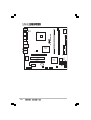
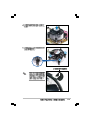
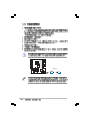
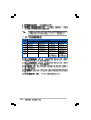
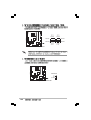
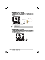
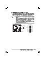
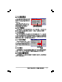
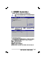
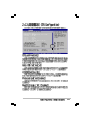
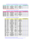
Motherboard
P5LD2-VM SE
T2727
© 2006
2
3
4
5
•
•
•
•
•
•
•
•
•
•
•
•
6
•
•
•
7
2 3
1 2
Jumper Mode
Jumper Free
(Default)
P5LD2-VM SE-TAYVZ
6
10839 11036
11XXX11XXX11
8
0
®
®
®
®
®
®
®
®
9
10
1-1
®
®
®
®
1-2
®
1-3
1-4
1-5
®
P5LD2-VM SE
SB_PWR
P5LD2-VM SE Onboard LED
1-6
ON
Standby
Power
OFF
Powered
Off
1-7
®
P5LD2-VM SE
CPU_FAN
Super
I/O
PS/2KBMS
T: Mouse
B: Keyboard
COM1
®
Intel
GMCH
945G
Top:Rear Speaker Out
Center:
Side Speaker Out
Below:
Center/Subwoofer
Top:Line In
Center:Line Out
Below:Mic In
FLOPPY
EATXPWR
LAN_USB34
DDR2 DIMM_B2 (64 bit,240-pin module)
F_USB12
DDR2 DIMM_A2 (64 bit,240-pin module)
VGA1
P5LD2-VM SE
®
PARALLEL PORT
LGA775
CHA_FAN
Intel
Gigabit LAN
PRI_IDE
PCIEX16
Intel FWH
4Mb
®
Intel
ICH7
SB_PWR
PCI2
SATA3
CD
PCIEX1_1
CR2032 3V
Lithium Cell
CMOS Power
SATA1
1-8
SPDIF_OUT
SATA4
SATA2
BUZZ
CLRTC
AAFP
PLED
CHASSIS
SPEAKER
PCI1
USB56
USB78
F_PANEL
ATX12V
•
•
•
®
P5LD2-VM SE
•
P5LD2-VM SE CPU Socket 775
1-9
A
B
B
A
1-10
A
B
1-11
•
•
•
1-12
B
A
A
B
B
A
®
A
P5LD2-VM SE
B
CPU_FAN
CPU FAN PWM
CPU FAN IN
CPU FAN PWR
GND
P5LD2-VM SE CPU fan connector
1-13
B
A
A
B
1-14
A
B
B
A
1-15
•
•
•
•
1-16
DIMM_B2
DIMM_A2
®
P5LD2-VM SE
P5LD2-VM SE 240-pin DDR2 DIMM sockets
512MB
256MB
512MB
512MB
256MB
1024MB
512MB
512MB
512MB
1024MB
256MB
512MB
1024MB
256MB
512MB
512MB
512MB
1024MB
512MB
1024MB
SAMSUNG
SAMSUNG
SAMSUNG
Infineon
Infineon
Infineon
Infineon
CORSAIR
MICRON
MICRON
MICRON
MICRON
Kingston
Kingston
Kingston
Hynix
Hynix
Hynix
ELPIDA
ELPIDA
M378T6553BG0-CD5
M378T3253FG0-CD5
M378T6453FG0-CD5
HYS64T64000GU-3.7-A
HYS64T32000HU-3.7-A
HYS64T128020HU-3.7-A
HYS64T64000HU-3.7-A
CM2X512-4200
MT16HTF6464AG-53EB2
MT16HTF12864AY-53EA1
MT8HTF3264AY-53EB3
MT16HTF6464AY-53EB2
D6408TE7BL-37
E5116AB-5C-E
HY5PS56821F-C4
HYMP564U648-C4
HY5PS1282AFP-C3
HYMP512U648-C4
EBE51UD8ABFA-5C
EBE11UD8ABFA-5C-E
N/A
N/A
N/A
Infineon
Infineon
Infineon
Infineon
N/A
MICRON
MICRON
MICRON
MICRON
N/A
N/A
ELPIDA
N/A
N/A
N/A
ELPIDA
ELPIDA
SS
SS
DS
SS
SS
DS
SS
DS
DS
DS
SS
DS
DS
SS
SS
SS
SS
DS
DS
DS
K4T51083QB-GCD5
K4T56083QF-GCD5
K4T56083QF-GCD5
HYB18T512800AC37
HYB18T512160AF-3.7
HYB18T512800AF37
HYB18T512800AF37
N/A
4FBIID9BQM
4JAIID9CRZ
4FBIID9CHM
4FBIID9CHM
E5108AB-5C-E
HYB18T512160AC-3.7
E5108AB-5C-E
HY5PS12821F-C4
HYMP564U64AP8-C3
HY5PS12821FP-C4
E5108AB-5C-E
E5108AB-5C-E
•
•
•
•
•
•
•
•
•
•
•
•
•
•
•
•
•
•
•
•
•
•
•
•
•
•
•
•
•
•
•
•
•
•
•
•
•
•
512MB
1024MB
512MB
256MB
256MB
512MB
256MB
1024MB
256MB
512MB
1024MB
Hynix
Hynix
Hynix
MICRON
MICRON
Infineon
Infineon
Infineon
ELPIDA
ELPIDA
ELPIDA
HYMP564U64AP8-Y5
HYMP512U64AP8-Y4
HYMP564U64AP8-Y4
MT8HTF3264AY-667B5
MT8HTF3264AY-667B6
HYS64T64000HU-3S-A
HYS64T32000HU-3S-A
HYS64T128020HU-3S-A
EBE25UC8ABFA-6E-E
EBE51UD8AEFA-6E-E
EBE11UD8AEFA-6E-E
Hynix
Hynix
Hynix
MICRON
MICRON
Infineon
Infineon
Infineon
ELPIDA
ELPIDA
N/A
SS
DS
SS
SS
SS
SS
SS
DS
SS
SS
DS
HY5PS12821AFP-Y5
HY5PS12821AFP-Y4
HY5PS12821AFP-Y4
4SB42D9CZM
5FB42D9DPN
HYB18T512800AF3S
HYB18T512160AF-3S
HYB18T512800AF3S
E2508AB-GE-E
E5108AE-GE-E
N/A
•
•
•
•
•
•
•
•
•
•
•
•
•
•
•
•
•
•
•
•
•
•
1-17
2
3
1
2
1
1
1-18
1-19
A
1-20
B
C
D
E
F
G
H
1-21
®
P5LD2-VM SE
CLRTC
1 2
P5LD2-VM SE Clear RTC RAM
1-22
Normal
(Default)
2 3
Clear CMOS
1
2
3
4
5
6
7
8
14
13
12
11
10
9
1-23
1-24
®
P5LD2-VM SE
FLOPPY
NOTE: Orient the red markings on
the floppy ribbon cable to PIN 1.
PIN 1
P5LD2-VM SE Floppy disk drive connector
•
®
P5LD2-VM SE
•
P5LD2-VM SE IDE connector
PRI_IDE
NOTE: Orient the red markings
(usually zigzag) on the IDE
ribbon cable to PIN 1.
PIN 1
1-25
1-26
®
P5LD2-VM SE
P5LD2-VM SE Speaker out connector
GND
RSATA_TXP2
RSATA_TXN2
GND
RSATA_RXP2
RSATA_RXN2
GND
GND
RSATA_TXP1
RSATA_TXN1
GND
RSATA_RXP1
RSATA_RXN1
GND
SATA3
SATA4
SATA1
SATA2
P5LD2-VM SE SATA connectors
SPEAKER
+5V
GND
GND
Speak Out
1
®
GND
RSATA_RXN4
RSATA_RXP4
GND
RSATA_TXN4
RSATA_TXP4
GND
GND
RSATA_RXN3
RSATA_RXP3
GND
RSATA_TXN3
RSATA_TXP3
GND
P5LD2-VM SE
®
P5LD2-VM SE
CPU_FAN
CPU FAN PWM
CPU FAN IN
CPU FAN PWR
GND
CHA_FAN
GND
+12V
Rotation
P5LD2-VM SE Fan connectors
1-27
SPDIFOUT
GND
+5V
®
P5LD2-VM SE
SPDIF_OUT
®
P5LD2-VM SE
P5LD2-VM SE Digital audio connector
PLED
PLEDNC
PLED+
1
P5LD2-VM SE Power LED connector
1-28
•
•
•
®
P5LD2-VM SE
EATXPWR
P5LD2-VM SE ATX power
+3 Volts
+12 Volts
GND +12V DC
+12 Volts
+5V Standby
Power OK
Ground
GND +12V DC
+5 Volts
Ground
+5 Volts
Ground
+3 Volts
connectors
+3 Volts
ATX12V
Ground
+5 Volts
+5 Volts
+5 Volts
-5 Volts
Ground
Ground
Ground
PSON#
Ground
-12 Volts
+3 Volts
1-29
®
P5LD2-VM SE
CD
Right Audio Channel
Ground
Ground
Left Audio Channel
P5LD2-VM SE USB 2.0 connectors
1-30
1
USB+5V
USB_P7USB_P7+
GND
USB78
1
USB+5V
USB_P5USB_P5+
GND
USB56
USB+5V
USB_P8USB_P8+
GND
NC
USB+5V
USB_P6USB_P6+
GND
NC
®
P5LD2-VM SE
P5LD2-VM SE CD audio connector
MIC2
MICPWR
Line out_R
NC
Line out_L
NC
AGND
NC
NC
SENSE2_RETUR
Legacy AC’97
compliant definition
PORT1 L
PORT1 R
PORT2 R
SENSE_SEND
PORT2 L
GND
PRESENCE#
SENSE1_RETUR
P5LD2-VM SE
®
AAFP
Azalia
compliant definition
®
P5LD2-VM SE
P5LD2-VM SE Analog front panel connector
CHASSIS
GND
Chassis Signal
(Default)
+5VSB_MB
P5LD2-VM SE Chassis intrusion connector
1-31
®
P5LD2-VM SE
F_PANEL
PWRSW
PWRLED
GND
PWR
PWR_LEDPWR_LED+
Reset
Ground
IDE_LEDIDE_LED+
RESET
IDE LED
* Requires an ATX power supply.
P5LD2-VM SE System panel connector
•
•
•
•
1-32
2-1
2-2
EZFlash starting BIOS update
Checking for floppy...
EZFlash starting BIOS update
Checking for floppy...
Floppy found!
Reading file “P5LD2VMS.ROM”. Completed.
Start erasing.......|
Start Programming...|
Flashed successfully. Rebooting.
•
•
2-3
•
•
A:\>afudos /oOLDBIOS1.ROM
A:\>afudos /oOLDBIOS1.ROM
AMI Firmware Update Utility - Version 1.10
Copyright (C) 2002 American Megatrends, Inc. All rights reserved.
Reading flash ..... done
A:\>
2-4
A:\>afudos /iP5LD2VMS.ROM
A:\>afudos /iP5LD2VMS.ROM
AMI Firmware Update Utility - Version 1.10
Copyright (C) 2002 American Megatrends, Inc. All rights reserved.
Reading file ..... done
Erasing flash .... done
Writing flash .... 0x0008CC00 (9%)
A:\>afudos /iP5LD2VMS.ROM
AMI Firmware Update Utility - Version 1.10
Copyright (C) 2002 American Megatrends, Inc. All rights reserved.
Reading file ..... done
Erasing flash .... done
Writing flash .... 0x0008CC00 (9%)
Verifying flash .. done
A:\>
2-5
Bad BIOS checksum. Starting BIOS recovery...
Checking for floppy...
Bad BIOS checksum. Starting BIOS recovery...
Checking for floppy...
Floppy found!
Reading file “P5LD2VMS.ROM”. Completed.
Start flashing...
2-6
Bad BIOS checksum. Starting BIOS recovery...
Checking for floppy...
Bad BIOS checksum. Starting BIOS recovery...
Checking for floppy...
Floppy not found!
Checking for CD-ROM...
CD-ROM found.
Reading file “P5LD2VMS.ROM”. Completed.
Start flashing...
2-7
2-8
2-9
2-10
2-11
System Time
System Date
Legacy Diskette A
Primary IDE Master
Primary IDE Slave
Third IDE Master
Third IDE Slave
Fourth IDE Master
Fourth IDE Slave
IDE Configuration
System Information
2-12
:
:
:
:
:
:
[11:51:19]
[Thu 06/10/2004]
[1.44M, 3.5 in]
Use [ENTER], [TAB] or
[SHIFT-TAB] to select
a field.
[ST320413A]
[Pioneer CD-ROM ATA]
[Not Detected]
[Not Detected]
[Not Detected]
[Not Detected]
Use [+] or [-] to
configure the System
time.
System Time
System Date
Legacy Diskette A
[11:51:19]
[Thu 06/10/2004]
[1.44M, 3.5 in]
Primary IDE Master : [ST320413A]
Primary IDE Slave : [Pioneer CD-ROM ATA]
Third IDE Master : [Not Detected]
Third IDE Slave : [Not Detected]
Fourth IDE Master :
[Not Detected]
Fourth IDE Slave : [Not Detected]
IDE Configuration
Use [ENTER],
[TAB] or [SHIFTTAB] to select a
field.
Use [+] or [-] to
configure the
System time.
System Information
Advanced PCI/PnP Settings
WARNING: Setting wrong values in
below sections may cause system to
malfunction.
Plug And Play O/S
PCI Latency Timer
Allocate IRQ to PCI VGA
Palette Snooping
PCI IDE BusMaster
[No]
[64]
[Yes]
[Disabled]
[Enabled]
2-13
System Time
System Date
Legacy Diskette A
Primary IDE Master
Primary IDE Slave
Third IDE Master
Third IDE Slave
Fourth IDE Master
Fourth IDE Slave
IDE Configuration
System Information
2-14
:
:
:
:
:
:
[11:51:19]
[Thu 06/10/2004]
[1.44M, 3.5 in]
Use [ENTER], [TAB] or
[SHIFT-TAB] to select
a field.
[ST320413A]
[Pioneer CD-ROM ATA]
[Not Detected]
[Not Detected]
[Not Detected]
[Not Detected]
Use [+] or [-] to
configure the System
time.
Primary IDE Master
Device
Vendor
Size
LBA Mode
Block Mode
PIO Mode
Async DMA
Ultra DMA
SMART Monitoring
:
:
:
:
:
:
:
:
:
Hard Disk
ST320413A
20.0GB
Supported
16 Sectors
Supported
MultiWord DMA-2
Ultra DMA-5
Supported
Select the type of
device connected to
the system.
Type
[Auto]
LBA/Large Mode
[Auto]
Block(Multi-sector Transfer)[Auto]
PIO Mode
[Auto]
DMA Mode
[Auto]
Smart Monitoring
[Auto]
32Bit Data Transfer
[Disabled]
2-15
IDE Configuration
2-16
Configure SATA As
Onboard IDE Operate Mode
Enhanced Mode Support On
[Standard IDE]
[Enhanced Mode]
[S-ATA]
IDE Detect Time Out (Sec)
[35]
Set to [Compatible
Mode] when Legacy OS
(i.e. WIN ME, 98,
NT4.0, MS DOS is
used.
Set to [Enhanced Mode
when Native OS) i.e.
WIN 2000, WIN XP) is
used.
2-17
AMIBIOS
Version
Build Date
:0120
:05/11/05
Processor
Type
Speed
Count
:Genuine Intel(R) CPU 3.20GHz
:3200 MHz
:1
System Memory
Size
:512 MB
Appropriated:0 MB
Available
:504MB
2-18
Configure the USB
support.
JumperFree Configuration
USB Configuration
CPU Configuration
Chipset
Onboard Devices Configuration
PCI PnP
Configure System Frequency/Voltage
AI Overclocking
[Auto]
2-19
2-20
FSB 1066
266 MHZ
FSB 800
200 MHz
FSB 533
133 MHz
2-21
USB Configuration
Module Version - 2.23.0-F.4
USB Devices Enabled: None
USB Function
Legacy USB Support
USB 2.0 Controller
USB 2.0 Controller Mode
BIOS EHCI Hand-off
2-22
[Enabled]
[Auto]
[Enabled]
[HiSpeed]
[Disabled]
Configure Advanced CPU settings
Manufacturer:
Brand String:
Frequency
:
FSB Speed
:
Cache L1
Cache L2
Cache L3
Intel
Genuine Intel(R) CPU 3.20GHz
3200 MHz
800 MHz
: 16 KB
: 1024 KB
: 0 KB
Sets the ratio between
CPU Core Clock and the
FSB Frequency.
NOTE: If an invalid
ratio is set in CMOS
then actual and
setpoint values may
differ.
Ratio Status: Unlocked (Max:16,
Ratio Actual Value : 16
Ratio CMOS Setting:
VID CMOS Setting:
Microcode Updation:
Max CPUID Value Limit:
Enhanced C1 Control
CPU Internal Thermal Control
[ 14]
[ 45]
[Enabled]
[Disabled]
[Auto]
[Auto]
Min:14)
+F1
F10
ESC
Select Screen
Select Item
Change Option
General Help
Save and Exit
Exit
Hyper Threading Technology
Intel(R) SpeedStep(tm) Tech.
[Enabled]
[Automatic]
F10
ESC
p
Save and Exit
Exit
2-23
2-24
Advanced Chipset Settings
Configure DRAM Timing by SPD
[Enabled]
Booting Graphic Adapter Priori [PCI Express/Int-VG]
Internal Graphics Mode Select
[Enabled, 8MB]
Graphics memory type
[Auto]
2-25
Configure Win627EHF Super IO Chipset
HD Audio Controller
[Enabled]
Onboard PCIEX GbE LAN
[Enabled]
LAN Option ROM
[Disabled]
Serial Port1 Address
Parallel Port Address
Parallel Port Mode
ECP Mode DMA Channel
Parallel Port IRQ
2-26
[3F8/IRQ4]
[378]
[ECP]
[DMA3]
[IRQ7]
Enable or disable
High Definition Audio
Controller.
2-27
Advanced PCI/PnP Settings
WARNING: Setting wrong values in below sections
may cause system to malfunction.
2-28
Plug And Play O/S
PCI Latency Timer
Allocate IRQ to PCI VGA
Palette Snooping
[No]
[64]
[Yes]
[Disabled]
IRQ-3 assigned to
IRQ-4 assigned to
IRQ-5 assigned to
IRQ-7 assigned to
IRQ-9 assigned to
IRQ-10 assigned to
IRQ-11 assigned to
IRQ-14 assigned to
IRQ-15 assigned to
[PCI
[PCI
[PCI
[PCI
[PCI
[PCI
[PCI
[PCI
[PCI
Device]
Device]
Device]
Device]
Device]
Device]
Device]
Device]
Device]
Available: Specified
IRQ is available to be
used by PCI/PnP
devices.
Reserved: Specified
IRQ is reserved for
use by Legacy ISA
devices.
Suspend Mode
ACPI 2.0 Support
ACPI APIC Support
[Auto]
[No]
[Enabled]
Select the ACPI state
used for System
Suspend.
APM Configuration
Hardware Monitor
2-29
2-30
APM Configuration
Power Button Mode
[On/Off]
Restore on AC Power Loss
Power On By RTC Alarm
Power On By External Modems
Power On By PCI Devices
Power On By PCIE Devices
[Power Off]
[Disabled]
[Disabled]
[Disabled]
[Disabled]
Go into On/Off or
Suspend when Power
button is pressed.
2-31
2-32
Hardware Monitor
CPU Temperature
MB Temperature
[51ºC/122.5ºF]
[41ºC/105.5ºF]
CPU Fan Speed (RPM)
CPU Q-Fan Control
Chassis Fan Speed (RPM)
[3813 RPM]
[Disabled]
[N/A]
VCORE Voltage
3.3V Voltage
5V Voltage
12V Voltage
[ 1.320V]
[ 3.345V]
[ 5.094V]
[11.880V]
CPU Temperature
2-33
Boot Settings
Specifies the Boot
Device Priority
sequence
Boot Device Priority
Boot Settings Configuration
Security
Boot Device Priority
1st Boot Device
2nd Boot Device
3rd Boot Device
2-34
[1st FLOPPY DRIVE]
[PM-ST330620A]
[PS-Pioneer CD-ROM]
Boot Settings Configuration
Quick Boot
Full Screen Logo
AddOn ROM Display Mode
Bootup Num-Lock
PS/2 Mouse Support
Wait For ‘F1’ If Error
Hit ‘DEL’ Message Display
Interrupt 19 Capture
[Enabled]
[Enabled]
[Force BIOS]
[On]
[Auto]
[Enabled]
[Enabled]
[Disabled]
Allows BIOS to skip
certain tests while
booting. This will
decrease the time
needed to boot the
system.
2-35
Security Settings
Supervisor Password
User Password
: Not Installed
: Not Installed
Change Supervisor Password
2-36
<Enter> to change
password.
<Enter> again to
disabled password.
Security Settings
Supervisor Password
User Password
: Not Installed
: Not Installed
Change Supervisor Password
User Access Level
Change User Password
Clear User Password
Password Check
[Setup]
Boot Sector Virus Protection
[Disabled]
[Full Access]
2-37
Exit Options
Exit & Save Changes
Exit & Discard Changes
Discard Changes
Load Setup Defaults
2-38
2-39
2-40
3-1
3-2
3-3
3-4
3-5
3-6