1
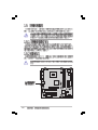
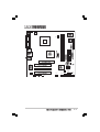
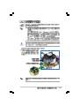
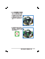
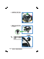
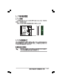
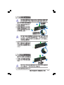
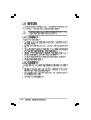
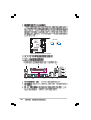
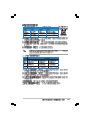
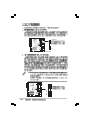
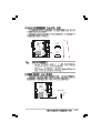
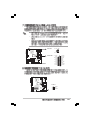
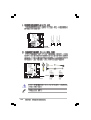
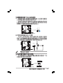
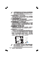
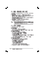
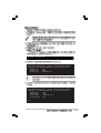
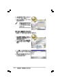
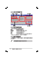
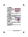
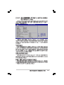
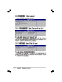
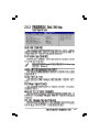
Motherboard
P5S800-VM
T1832
© 2004
2
3
4
5
6
•
•
•
•
•
•
•
•
•
•
•
•
7
•
•
•
8
™
1 2
Jumper Mode
2 3
Jumper Free
(Default)
9
P5S800-VM -TAYZ
6
10839 11036
11XX11XX11
10
0
®
®
®
®
®
11
12
®
®
®
®
1-2
®
®
®
1-3
1-4
®
P5S800-VM
SB_PWR1
ON
Standby
Power
OFF
Powered
Off
P5S800-VM Onboard LED
1-5
1-6
®
P5S800-VM
KBPWR1
ATX12V1
COM1
LGA775
CPU_FAN1
®
P5S800-VM
VGA1
SB_PWR1
SATA2
CHA_FAN1
CHASSIS1
USB56
FP_AUDIO
AUX1
CD1
SPDIF1
CLRTC1
PLED1
IR_CON1
SATA1
USB78
F_PANEL
COM2
GAME1 SPEAKER1
1-7
®
®
•
•
•
®
P5S800-VM
•
P5S800-VM CPU Socket 775
1-8
®
A
B
1-9
A
B
®
®
®
®
1-10
®
®
®
•
®
•
®
®
•
®
®
1-11
A
B
B
A
B
B
A
®
P5S800-VM
CPU_FAN1
P5S800-VM CPU fan connector
1-12
CPU FAN PWM
CPU FAN IN
CPU FAN PWR
GND
A
B
A
A
A
B
B
B
A
1-13
1-14
DIMM2
DIMM1
®
P5S800-VM
P5S800-VM 184-pin DDR DIMM sockets
1-15
1-16
•
•
•
•
•
•
•
•
•
•
•
•
•
•
•
•
•
•
•
•
•
•
•
•
•
•
•
•
•
•
•
•
•
•
•
•
•
•
•
•
•
•
•
•
•
•
•
•
•
•
•
•
•
•
•
•
•
•
•
•
•
•
•
•
•
•
•
•
•
•
•
•
•
•
•
•
2
3
1
1
2
1
1
2
1
1
1-17
1-18
A
B
C
D
E
F
G
H
1-19
®
P5S800-VM
Keyed for 1.5v
P5S800-VM Accelerated Graphics Port (AGP)
1-20
®
P5S800-VM
CLRTC1
2
1
Clear CMOS
P5S800-VM Clear RTC RAM
3
2
Normal
(Default)
1-21
KBPWR1
+5V
®
P5S800-VM
1 2
2 3
+5VSB
(Default)
P5S800-VM Keyboard power setting
1
2
3
4
5
6
11
1-22
10
9
8
7
1-23
FLOPPY1
®
P5S800-VM
NOTE: Orient the red markings on
the floppy ribbon cable to PIN 1.
PIN 1
P5S800-VM Floppy disk drive connector
•
NOTE: Orient the red markings
(usually zigzag) on the IDE
ribbon cable to PIN 1.
P5S800-VM IDE connectors
1-24
PRI_IDE1
SEC_IDE1
®
P5S800-VM
•
PIN 1
®
P5S800-VM
GND
RSATA_RXN1
RSATA_RXP1
GND
RSATA_TXN1
RSATA_TXP1
GND
®
P5S800-VM
SATA2
P5S800-VM SATA connectors
SATA1
•
•
SPEAKER1
Speak Out
GND
GND
+5V
P5S800-VM Speaker out connector
1
1-25
GND
RSATA_RXN2
RSATA_RXP2
GND
RSATA_TXN2
RSATA_TXP2
GND
CPU_FAN1
®
P5S800-VM
CPU FAN PWM
CPU FAN IN
CPU FAN PWR
GND
GND
+12V
Rotation
CHA_FAN1
SPDIFOUT
GND
+5V
®
P5S800-VM
P5S800-VM Fan connectors
SPDIF1
P5S800-VM Digital audio connector
1-26
•
•
•
ATX12V1
+12V DC GND
®
P5S800-VM
+12V DC GND
ATXPWR1
+5.0VDC
+5.0VDC
-5.0VDC
COM
COM
COM
PS_ON#
COM
-12.0VDC
+3.3VDC
®
P5S800-VM
P5S800-VM ATX power connectors
+12.0VDC
+5VSB
PWR_OK
COM
+5.0VDC
COM
+5.0VDC
COM
+3.3VDC
+3.3VDC
PLED1
PLEDNC
PLED+
1
P5S800-VM PLED connector
1-27
1-28
1
P5S800-VM USB 2.0 connectors
USB+5V
USB_P5USB_P5+
GND
USB56
1
USB+5V
USB_P7USB_P7+
GND
USB+5V
USB_P8USB_P8+
GND
NC
USB+5V
USB_P6USB_P6+
GND
NC
®
P5S800-VM
P5S800-VM Internal audio connectors
AUX1 (White) CD1 (Black)
USB78
Right Audio Channel
Ground
Left Audio Channel
Right Audio Channel
Ground
Left Audio Channel
®
P5S800-VM
BLINE_OUT_L
AGND
+5VA
BLINE_OUT_R
®
P5S800-VM
MIC2
MICPWR
Line out_R
NC
Line out_L
FP_AUDIO1
P5S800-VM Front panel audio connector
PIN 1
®
P5S800-VM
COM2
P5S800-VM Serial port connector
PLED+
PLEDPWR
GND
®
P5S800-VM
PLED PWRBTN*
HDLED+
HDLEDGround
Reset
F_PANEL1
HDLED RESET
P5S800-VM System panel connector
1-29
Chassis Signal
GND
+5VSB_MB
®
P5S800-VM
CHASSIS1
(Default)
P5S800-VM Chassis intrusion connector
1-30
2-1
2-2
EZFlash starting BIOS update
Checking for floppy...
EZFlash starting BIOS update
Checking for floppy...
Floppy found!
Reading file “P5S800VM.rom”. Completed.
Start erasing.......|
Start programming...|
Flashed successfully. Rebooting.
•
•
2-3
•
•
A:\>afudos /oOLDBIOS1.ROM
A:\>afudos /oOLDBIOS1.ROM
AMI Firmware Update Utility - Version 1.10
Copyright (C) 2002 American Megatrends, Inc. All rights reserved.
Reading flash ..... done
Write to file ...ok
A:\>
2-4
A:\>afudos /iP5S800VM.ROM
A:\>afudos /iP5S800VM.ROM
AMI Firmware Update Utility - Version 1.19(ASUS V2.07(03.11.24BB))
Copyright (C) 2003 American Megatrends, Inc. All rights reserved.
Reading file ..... done
Erasing flash .... done
Writing flash .... 0x0008CC00 (9%)
A:\>afudos /iP5S800VM.ROM
AMI Firmware Update Utility - Version 1.19(ASUS V2.07(03.11.24BB))
Copyright (C) 2003 American Megatrends, Inc. All rights reserved.
Reading file ...... done
Erasing flash ..... done
Writing flash ..... 0X0008CC00 (9%)
Verifying flash ... done
A:\>
2-5
Bad BIOS checksum. Starting BIOS recovery...
Checking for floppy...
Bad BIOS checksum. Starting BIOS recovery...
Checking for floppy...
Floppy found!
Reading file “P5S800VM.ROM”. Completed.
Start flashing...
2-6
Bad BIOS checksum. Starting BIOS recovery...
Checking for floppy...
Bad BIOS checksum. Starting BIOS recovery...
Checking for floppy...
Floppy not found!
Checking for CD-ROM...
CD-ROM found!
Reading file “P5S800VM.ROM”. Completed.
Start flashing...
2-7
2-8
2-9
2-10
2-11
System Time
System Date
Legacy Diskette A
Primary IDE Master
Primary IDE Slave
Secondary IDE Master
Secondary IDE Slave
OnChip SATA Controller
System Information
2-12
[11:51:19]
[Thu 10/07/2004]
[1.44M, 3.5 in]
:[ST320413A]
:[ASUS CD-S360]
:[Not Detected]
:[Not Detected]
[Enabled]
Use [ENTER], [TAB]
or [SHIFT-TAB] to
select a field.
Use [+] or [-] to
configure system time.
System Time
System Date
Legacy Diskette A
Language
Primary IDE Master
Primary IDE Slave
Secondary IDE Master
Secondary IDE Slave
Third IDE Master
Fourth IDE Master
IDE Configuration
[11:10:19]
[Thu 03/27/2003]
[1.44M, 3.5 in]
[English]
:[ST320413A]
:[ASUS CD-S340]
:[Not Detected]
:[Not Detected]
:[Not Detected]
:[Not Detected]
System Information
Use [ENTER], [TAB]
or [SHIFT-TAB] to
select a field.
Use [+] or [-] to
configure system time.
+Tab
F1
F10
ESC
Select Screen
Select Item
Change Field
Select Field
General Help
Save and Exit
Exit
+F1
F10
ESC
Select Screen
Select Item
Change Option
General Help
Save and Exit
Exit
Advanced Chipset settings
WARNING: Setting wrong values in the sections below
may cause system to malfunction.
Configure DRAM Timing by SPD
Memory Acceleration Mode
DRAM Idle Timer
DRAm Refresh Rate
[Enabled]
[Auto]
[Auto]
[Auto]
Graphic Adapter Priority
Graphics Aperture Size
Spread Spectrum
[AGP/PCI]
[ 64 MB]
[Enabled]
ICH Delayed Transaction
[Enabled]
MPS Revision
[1.4]
2-13
System Time
System Date
Legacy Diskette A
Language
Primary IDE Master
Primary IDE Slave
Secondary IDE Master
Secondary IDE Slave
OnChip SATA Controller
System Information
2-14
[11:51:19]
[Thu 10/07/2004]
[1.44M, 3.5 in]
[English]
:[ST320413A]
:[ASUS CD-S360]
:[Not Detected]
:[Not Detected]
[Enabled]
Primary IDE Master
Device
: Hard Disk
Vendor
: ST320413A
Size
: 20.0GB
LBA Mode
: Supported
Block Mode
: 16 Sectors
PIO Mode
: 4
Async DMA
: MultiWord DMA-2
Ultra DMA
: Ultra DMA-5
SMART Monitoring: Supported
Type
LBA/Large Mode
Block(Multi-sector Transfer)
PIO Mode
DMA Mode
Smart Monitoring
32Bit Data Transfer
[Auto]
[Auto]
[Auto]
[Auto]
[Auto]
[Auto]
[Disabled]
2-15
AMIBIOS
Version
: 08.00.10
Build Date : 10/07/04
Processor
Type
Speed
Count
: Genuine Intel(R) CPU 3.20GHz
: 2800 MHz
: 1
System Memory
Size
: 512MB
2-16
JumperFree Configuration
CPU Configuration
Chipset
Onboard Devices Configuration
PCI PnP
USB Configuration
Instant Music Configuration
Configure CPU.
Enter
F1
F10
ESC
Configure System Frequency/Voltage
Spread Spectrum
DRAM Frequency
CPU Vcore Offset +0.1V
AGP VDDQ Voltage
DDR Reference Voltage
[Enabled]
[Auto]
[Disabled]
[Auto]
[Auto]
Select Screen
Select Item
Go to Sub-screen
General Help
Save and Exit
Exit
Select the target CPU
frequency, and the
relevant parameters
will be auto-adjusted.
Frequencies higher
than CPU manufacturer
recommends are not
guaranteed to be
stable. If the system
becomes unstable,
return to the default.
2-17
2-18
Configure Advanced CPU settings
Manufacturer: Intel
Brand String: Genuine Intel(R)
Frequency
: 2806 MHz
FSB Speed
: 800 MHz
Cache L1
: 16 KB
Cache L2
: 1024 KB
Cache L3
: 0 KB
Ratio Status: Unlocked
Ratio Actual Value : 14
Ratio CMOS Setting:
Microcode Updation
Max CPUID Value Limit:
Enhanced C1 Control
CPU Internal Thermal Control
Hyper Threading Technology
CPU 2.80GHz
[ 16]
[Enabled]
[Disabled]
[Auto]
[Auto]
[Enabled]
+F1
F10
ESC
Select Screen
Select Item
Change Option
General Help
Save and Exit
Exit
2-19
NorthBridge SiS661FX Configuration
SouthBridge SiS964 Configuration
2-20
Primary Graphics Adapter
MA 1T/2T Select
DRAM CAS# Latency
DRAM Precharge Delay
DRAM RAS# to CAS# Delay
DRAM RAS# Precharge
Graphic Win Size
AGP Fast Write Control
[PCI]
[Auto]
[By SPD]
[Auto]
[Auto]
[Auto]
[ 64MB]
[Disabled]
Share Memory Size
[ 32MB]
Onboard AC97 Device
[Enabled]
Configure Win637 Super IO Chipset
Serial Port1 Address
Serial Port2 Address
Parallel Port Address
Parallel Port Mode
ECP Mode DMA Channel
Parallel Port IRQ
Onboard Game/MIDI Port
[3F8/IRQ4]
[2F8/IRQ3]
[378]
[Normal]
[DMA3]
[IRQ7]
[Disabled]
Onboard RTL8100C LAN DEVICE
Onboard LAN Boot ROM
[Enabled]
[Disabled]
Select Screen
2-21
2-22
Advanced PCI/PnP Settings
WARNING: Setting wrong values in below sections
may cause system to malfunction.
Plug And Play O/S
PCI Latency Timer
Allocate IRQ to PCI VGA
Palette Snooping
PCI IDE BusMaster
[No]
[64]
[Yes]
[Disabled]
[Enabled]
IRQ3
IRQ4
IRQ5
IRQ7
IRQ9
IRQ10
IRQ11
IRQ14
IRQ15
[PCI
[PCI
[PCI
[PCI
[PCI
[PCI
[PCI
[PCI
[PCI
Device]
Device]
Device]
Device]
Device]
Device]
Device]
Device]
Device]
+F1
F10
ESC
Select Screen
Select Item
Change Option
General Help
Save and Exit
Exit
2-23
Onboard SiS USB1.1 DEVICE
Onboard SiS USB2.0 DEVICE
[Enabled]
[Enabled]
Enables USB host
controllers.
USB Devices Enabled: None
Module Version - 2.23.2-9.4
USB Device Enabled : None
Legacy USB Support
USB 2.0 Controller Mode
Stop EHCT HC in OHCT handover
[Auto]
[Enabled]
[Enabled]
Select Screen
2-24
Instant Music Option
Instant Music
[Enabled]
2-25
Suspend Mode
ACPI 2.0 Support
ACPI APIC Support
APM Configuration
Hardware Monitor
2-26
[Auto]
[No]
[Enabled]
Configure CPU.
Power Button Mode
[On/Off]
Restore on AC Power Loss
Power On By PS/2 Keyboard
Power On By PS/2 Mouse
Power On By PCI Devices
Power On By External Modems
Power On By RTC Alarm
[Always OFF]
[Disabled]
[Disabled]
[Disabled]
[Disabled]
[Disabled]
Enabled or disable
APM.
2-27
Hardware Monitor
CPU Temperature
MB Temperature
[51ºC/122.5ºF]
[41ºC/105.5ºF]
CPU Fan Speed
Chassis Fan Speed
Power Fan Speed
[3813 RPM]
[N/A]
[N/A]
VCORE Voltage
3.3V Voltage
5V Voltage
12V Voltage
[ 1.320V]
[ 3.345V]
[ 5.094V]
[11.880V]
+F1
2-28
Select Screen
Select Item
Change Option
General Help
2-29
APM Configuration
Boot Device Priority
Boot Settings Configuration
Security
Boot Device Priority
1st Boot Device
2nd Boot Device
3rd Boot Device
[1st FLOPPY DRIVE]
[PM-ST330620A]
[PS-ASUS CD-S360]
Hard Disk Devices
1st Device
2nd Device
2-30
[PM-IBM-DJNA-371350]
[Maxtor 6B200M0]
Boot Settings Configuration
Quick Boot
Full Screen Logo
AddOn ROM Display Mode
Bootup Num-Lock
PS/2 Mouse Support
Wait For ‘F1’ If Error
Hit ‘DEL’ Message Display
Interrupt 19 Capture
[Enabled]
[Enabled]
[Force BIOS]
[On]
[Auto]
[Enabled]
[Enabled]
[Disabled]
Allows BIOS to skip
certain tests while
booting. This will
decrease the time
needed to boot the
system.
2-31
Security Settings
Supervisor Password
User Password
: Not Installed
: Not Installed
Change Supervisor Password
Boot Sector Virus Protection
2-32
[Disabled]
<Enter> to change
password.
<Enter> again to
disabled password.
Security Settings
Supervisor Password
User Password
: Not Installed
: Not Installed
Change Supervisor Password
User Access Level
Change User Password
Clear User Password
Password Check
[Setup]
Boot Sector Virus Protection
[Disabled]
[Full Access]
Select Screen
Select Item
2-33
Exit Options
Exit & Save Changes
Exit & Discard Changes
Discard Changes
Load Setup Defaults
Exit system setup
after saving the
changes.
F10 key can be used
for this operation.
Enter
F1
F10
ESC
2-34
Select Screen
Select Item
Go to Sub-screen
General Help
Save and Exit
Exit
2-35
2-36
3-2
3-3
3-4
3-5
3-6