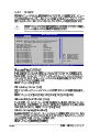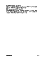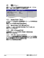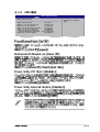
1
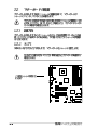
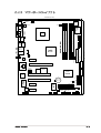
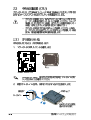
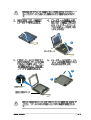
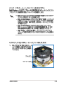
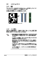
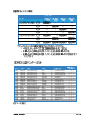
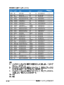
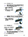
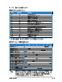
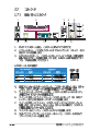
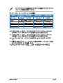
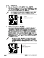
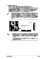
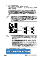
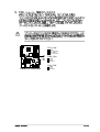
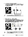
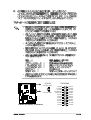
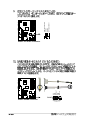
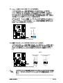
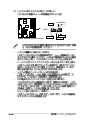
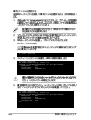
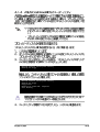
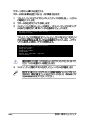
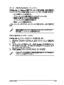
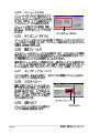
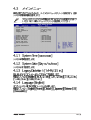
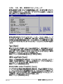
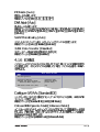
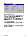
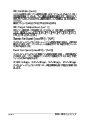
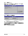
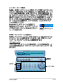
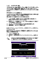
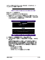
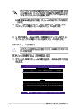
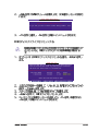
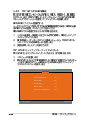
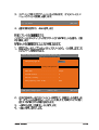
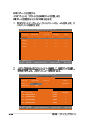
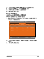
Motherboard
P5GD1
Checklist
Copyright© 2004 ASUSTeK COMPUTER INC. All Rights Reserved.
ii
iii
Features
Safeguards
iv
v
®
®
vi
Federal Communications Commission Statement
This device complies with Part 15 of the FCC Rules. Operation is
subject to the following two conditions:
• This device may not cause harmful interference, and
• This device must accept any interference received including
interference that may cause undesired operation.
This equipment has been tested and found to comply with the limits
for a Class B digital device, pursuant to Part 15 of the FCC Rules.
These limits are designed to provide reasonable protection against
harmful interference in a residential installation. This equipment
generates, uses and can radiate radio frequency energy and, if not
installed and used in accordance with manufacturer’s instructions,
may cause harmful interference to radio communications. However,
there is no guarantee that interference will not occur in a particular
installation. If this equipment does cause harmful interference to radio
or television reception, which can be determined by turning the
equipment off and on, the user is encouraged to try to correct the
interference by one or more of the following measures:
• Reorient or relocate the receiving antenna.
• Increase the separation between the equipment and receiver.
• Connect the equipment to an outlet on a circuit different from
that to which the receiver is connected.
• Consult the dealer or an experienced radio/TV technician for help.
The use of shielded cables for connection of the monitor to the
graphics card is required to assure compliance with FCC
regulations. Changes or modifications to this unit not expressly
approved by the party responsible for compliance could void the
user’s authority to operate this equipment.
Canadian Department of Communications
Statement
This digital apparatus does not exceed the Class B limits for radio
noise emissions from digital apparatus set out in the Radio
Interference Regulations of the Canadian Department of
Communications.
This class B digital apparatus complies with Canadian
ICES-003.
vii
viii
ix
afudos /i[filename]
afudos /iP5GD1.ROM
x
®
®
®
®
®
®
®
®
®
®
®
®
®
1
ASUS P5GD1
®
ASUS P5GD1
®
®
®
®
®
®
®
®
®
®
®
®
®
ASUS P5GD1
®
™
2
ASUS P5GD1
P5GD1
P5GD1 Onboard LED
ASUS P5GD1
SB_PWR
ON
Standby
Power
OFF
Powered
Off
2-1
P5GD1
2-2
24.5cm (9.6in)
Intel FWH
8Mbit
Below:
Intel
915P
Center/Subwoofer
Top:Line In
Center:Line Out
Below:Mic In
CD
Super
I/O
FLOPPY1
WL_LED
C-Media
CMI9880
PWR_FAN1
AAFP
WL_ANT
PCIEX1_1
30.5cm (12.0in)
Side Speaker Out
PRI_IDE1
Top:Rear Speaker Out
Center:
DDR2 DIMM_B1 (64 bit,240-pin module)
USB2.0 Top:
T: USB3 RJ-45
B: USB4
DDR2 DIMM_B2 (64 bit,240-pin module)
P5GD2 PRO
Top:
USB1
USB2 1394
DDR2 DIMM_A2 (64 bit,240-pin module)
PARALLEL PORT
Bottom:
DDR2 DIMM_A1 (64 bit,240-pin module)
CPU_FAN1
ATX12V1
USBPW34
USBPW12
SPDIF_O2
SPDIF_O
KB1
CHA_FAN2
EATXPWR1
MS1
KBPWR1
PCIEX16
TI TSB82AA2
CR2032 3V
Lithium Cell
CMOS Power
Marvell
88E8001
PCI3
CLRTC1
Speech
Controller
ITE
8212F
PCIEX1_2
PCIEX1_3
COM1
USBPW56
USBPW78
LAN2
CHA_FAN1 USB56
ASUS P5GD1
SEC_RAID1
SATA4
Intel
ICH6R
PCI2
Marvell
88E8053
SATA3
TSB81BA3
SATA2
IE1394B_2
IE1394B_1
SATA1
88W8000G
USB78
PRI_RAID1
CHASSIS1
SB_PWR1
GAME1
PANEL1
2-3
2-4
ASUS P5GD1
2-5
®
P5GD1
P5GD1 Socket 775
A
B
2-6
®
B
A
A
B
ASUS P5GD1
2-7
®
®
®
®
®
®
2-8
®
®
®
®
®
®
®
®
ASUS P5GD1
®
®
2-9
2-10
CPU_FAN
GND
CPU FAN PWR
CPU FAN IN
CPU FAN PWM
P5GD1
ASUS P5GD1
2-11
P5GD1 184-Pin DDR DIMM Sockets
2-12
DIMM_B2
DIMM_B1
DIMM_A2
DIMM_A1
P5GD1
DIMM
A* B*C*
256MB
512MB
256MB
512MB
256MB
512MB
512MB
256MB
512MB
256MB
512MB
256MB
512MB
256MB
512MB
256MB
512MB
256MB
512MB
256MB
512MB
512MB
KINGSTON
KINGSTON
KINGSTON
KINGSTON
KINGSTON
KINGSTON
KINGSTON
SAMSUNG
SAMSUNG
SAMSUNG
SAMSUNG
Hynix
Hynix
MICRON
MICRON
Infineon
Infineon
Infineon
Infineon
CORSAIR
CORSAIR
CORSAIR
ASUS P5GD1
KVR400X64C3A/256
KVR400X64C3A/512
KVR400X64C3A/256
KVR400X64C3A/512
KVR400X64C3A/256
KVR400X64C3A/512
KHX3200A/512
M368L3223ETM-CCC
M368L6423ETM-CCC
M368L3223FTN-CCC
M368L6423FTN-CCC
HYMD232646B8J-D43 AA
HYMD264646B8J-D43 AA
MT8VDDT3264AG-40BCB
MT16VDDT6464AG-40BCB
HYS64D32300GU-5-B
HYS64D64320GU-5-B
HYS64D32300HU-5-C
HYS64D64320HU-5-C
CMX256A-3200C2PT
CMX512-3200C2
VS512MB400
Hynix
Hynix
Infineon
Infineon
KINGSTON
KINGSTON
N/A
SAMSUNG
SAMSUNG
SAMSUNG
SAMSUNG
Hynix
Hynix
MICRON
MICRON
Infineon
Infineon
Infineon
Infineon
Winbond
Winbond
VALUE seLecT
SS
DS
SS
DS
SS
DS
DS
SS
DS
SS
DS
SS
DS
SS
DS
SS
DS
SS
DS
SS
DS
DS
HY5DU56822BT-D43
HY5DU56822BT-D43
HYB25D256800BT-5B
HYB25D256809BT-5B
D3208DL2T-5
D328DIB-50
Heat-Sink Package
K4H560838E-TCCC
K4H560838E-TCCC
K4H560838F-TCCC
K4H560838F-TCCC
HY5DU56822BT-D43
HY5DU56822BT-D43
MT46V32M8TG-5BC
MT46V32M8TG-5BC
HYB25D256800BT-5B
HYB25D256800BT-5B
HYB25D256800CE-5C
HYB25D256800CE-5C
W942508BH-5
Heat-Sink Package
VS32M8-5
•
•
•
•
•
•
•
•
•
•
•
•
•
•
•
•
•
•
•
•
•
•
•
•
•
•
•
•
•
•
•
•
•
•
•
•
•
•
•
•
•
•
•
•
•
•
•
•
2-13
DIMM
A* B*C*
256MB
512MB
256MB
512MB
256MB
256MB
512MB
256MB
512MB
1024MB
256MB
512MB
256MB
512MB
256MB
512MB
256MB
512MB
256MB
512MB
256MB
512MB
512MB
256MB
512MB
256MB
512MB
512MB
1024MB
256MB
512MB
256MB
512MB
256MB
512MB
256MB
512MB
256MB
512MB
256MB
512MB
256MB
512MB
256MB
512MB
256MB
512MB
2-14
GEIL
GEIL
GEIL
GEIL
TwinMOS
TwinMOS
TwinMOS
Transcend
Transcend
Transcend
Transcend
Transcend
Transcend
Transcend
A DATA
A DATA
A DATA
A DATA
A DATA
A DATA
Winbond
Winbond
PSC
PSC
PSC
KINGMAX
KINGMAX
ATP
ATP
NANYA
NANYA
BRAIN POWER
BRAIN POWER
CENTURY
CENTURY
CENTURY
CENTURY
CENTURY
CENTURY
elixir
elixir
Kreton
Kreton
Veritech
Veritech
Pmi
Pmi
GE2563200B
GE5123200B
GD3200-256V
GD3200-512V
M2S9I08AFAPS9F0811A-T
M2G9I08AIATT9F081AADT
M2G9J16AJATT9F081AADT
TS32MLD64V4F3
TS64MLD64V4F3
TS128MLD64V4J
TS32MLD64V4F3
TS64MLD64V4F3
TS32MLD64V4F3
TS64MLD64V4F3
MDOSS6F3G31Y0K1E0Z
MDOSS6F3H41Y0N1E0Z
MDOHY6F3G31Y0N1E0Z
MDOHY6F3H41Y0N1E0Z
MDOAD5F3G31Y0D1E02
MDOAD5F3H41Y0D1E02
W9425GCDB-5
W9451GCDB-5
AL6D8A53T1-5B
AL5D8B53T-5B1K
AL6D8B53T-5B1K
MPXB62D-38KT3R
MPXC22D-38KT3R
AG64L64T8SQC4S
AG28L64T8SMC4M
NT256D64S88B1G-5T
N512D64S8HB1G-5T
B6U808-256M-SAM-400
B6U808-512M-SAM-400
DXV6S8SSCCD3K27C
DXV2S8SSCCD3K27C
DXV6S8SSCCE3K27E
DXV2S8SSCCE3K27E
DXV6S8MC5BC3U27E
DXV2S8MC5BC3U27E
M2U25664DS88B3G-5T
M2U25664DS8HB3G-5T
N/A
N/A
VT400FMV/2561103
VT400FMV/5121003
MD44256VIT3208GMHA01
MD44512VIT3208GATA03
GEIL
GEIL
GEIL
GEIL
PSC
TwinMOS
TwinMOS
N/A
N/A
N/A
Mosel
Mosel
SAMSUNG
SAMSUNG
SAMSUNG
SAMSUNG
Hynix
Hynix
N/A
N/A
Winbond
Winbond
PSC
PSC
PSC
N/A
N/A
SAMSUNG
MICRON
NANYA
NANYA
SAMSUNG
SAMSUNG
SAMSUNG
SAMSUNG
SAMSUNG
SAMSUNG
MICRON
MICRON
NANYA
NANYA
VT
VT
VT
VT
MOSEL
MOSEL
SS
DS
SS
DS
SS
SS
DS
SS
DS
DS
SS
DS
SS
DS
SS
DS
SS
DS
SS
DS
SS
DS
DS
SS
DS
SS
DS
DS
DS
SS
DS
SS
DS
SS
DS
SS
DS
SS
DS
SS
DS
SS
DS
SS
DS
SS
DS
GL3LC32G88TG-5A
GL3LC32G88TG-5A
GLIL DDR 32M8
GLIL DDR 32M8
A2S56D30ATP
TMD7608F8E50D
TMD7608F8E50D
K4H560838F-TCCC
K4H560838F-TCCC
K4H510838B-TCCC
V58C2256804SAT5B
V58C2256804SAT5B
K4H560838E-TCCC
K4H560838E-TCCC
K4H560838E-TCCC
K4H560838F-TCCC
HY5DU56822CT-D43
HY5DU56822CT-D43
ADD8608A8A-5B
ADD8608A8A-5B
W942508CH-5
W942508CH-5
A2S56D30ATP
A2S56D30BTP
A2S56D30BTP
KDL388P4LA-50
KDL388P4LA-50
K4H560838D-TCC4
MT46V64M4TG-5BC
NT5DS32M8BT-5T
NT5DS32M8BT-5T
K4H560838D-TCC4
K4H560838D-TCC4
K4H560838D-TCCC
K4H560838D-TCCC
K4H560838E-TCCC
K4H560838E-TCCC
MT46V32M8TG-5BC
MT46V32M8TG-5BC
N2DS25680BT-5T
N2DS25680BT-5T
VT3225804T-5
VT3225804T-5
VT56DD32M8PC-5
VT56DD32M8PC-5
V58C2256804SAT5B
V58C2256804SAT5B
•
•
•
•
•
•
•
•
•
•
•
•
•
•
•
•
•
•
•
•
•
•
•
•
•
•
•
•
•
•
•
•
•
•
•
•
•
•
•
•
•
•
•
•
•
•
•
•
•
•
•
•
•
•
•
•
•
•
•
•
•
•
•
•
•
•
•
•
•
•
•
•
•
•
•
•
•
•
•
•
•
•
•
•
•
•
•
•
•
•
•
•
•
•
•
•
•
•
•
•
•
•
•
•
•
•
•
•
•
•
•
•
•
•
•
•
•
•
•
2
1
1
2
1
1
ASUS P5GD1
2-15
2-16
—
—
—
—
—
—
—
—
—
—
—
ASUS P5GD1
—
—
—
—
—
—
—
—
—
—
—
—
—
—
—
—
—
—
—
—
—
—
—
—
—
—
—
—
—
—
—
—
—
—
—
—
—
—
—
—
—
—
—
—
—
—
—
—
—
—
—
—
—
—
—
—
—
—
—
—
—
—
—
—
—
—
—
—
—
—
—
—
—
—
—
—
—
—
—
—
—
—
—
—
—
—
—
—
—
—
—
—
—
—
2-17
2-18
CLRTC
P5GD1
1 2
P5GD1 Clear RTC RAM
ASUS P5GD1
Normal
(Default)
2 3
Clear CMOS
2-19
USBPW12
USBPW34
2 3
1 2
+5V
(Default)
USBPW56
USBPW78
P5GD1
1 2
P5GD1 USB device wake-up
2-20
+5VSB
+5V
(Default)
2 3
+5VSB
KBPWR
1 2
+5V
2 3
+5VSB
(Default)
P5GD1
P5GD1 Keyboard power setting
ASUS P5GD1
2-21
1
2
3
4
5
6
7
8
14
13
12
11
10
9
ACT/LINK SPEED
LED
LED
LAN port
2-22
ASUS P5GD1
2-23
FLOPPY
NOTE: Orient the red markings on
the floppy ribbon cable to PIN 1.
P5GD1
PIN 1
P5GD1 Floppy disk drive connector
PRI_IDE
NOTE: Orient the red markings
(usually zigzag) on the IDE
ribbon cable to PIN 1.
P5GD1
P5GD1 IDE connector
2-24
PIN 1
SEC_RAID
NOTE: Orient the red markings
(usually zigzag) on the IDE
cable to PIN 1.
P5GD1
PRI_RAID
PIN 1
P5GD1 RAID IDE connectors
ASUS P5GD1
2-25
®
®
SATA2
P5GD1
SATA1
P5GD1 SATA connectors
GND
RSATA_TXP2
RSATA_TXN2
GND
RSATA_RXN2
RSATA_RXP2
GND
GND
RSATA_TXP1
RSATA_TXN1
GND
RSATA_RXN1
RSATA_RXP1
GND
SATA4
SATA3
GND
RSATA_TXP4
RSATA_TXN4
GND
RSATA_RXN4
RSATA_RXP4
GND
GND
RSATA_TXP3
RSATA_TXN3
GND
RSATA_RXN3
RSATA_RXP3
GND
®
®
®
2-26
CPU_FAN
GND
CPU FAN PWR
CPU FAN IN
CPU FAN PWM
PWR_FAN
P5GD1
GND
+12V
Rotation
CHA_FAN
P5GD1 Fan connectors
ASUS P5GD1
GND
+12V
Rotation
2-27
P5GD1 USB 2.0 connectors
2-28
USB56
1
1
USB+5V
USB_P7USB_P7+
GND
USB+5V
USB_P8USB_P8+
GND
NC
USB+5V
USB_P6USB_P6+
GND
NC
P5GD1
USB+5V
USB_P5USB_P5+
GND
COM2
P5GD1
PIN 1
P5GD1 Serial port connectors
USB78
®
ATX12V
+12V DC GND
+12V DC GND
P5GD1
P5GD1 ATX power connectors
ASUS P5GD1
®
EATXPWR
+3 Volts
+12 Volts
+12 Volts
+5V Standby
Power OK
Ground
+5 Volts
Ground
+5 Volts
Ground
+3 Volts
+3 Volts
Ground
+5 Volts
+5 Volts
+5 Volts
-5 Volts
Ground
Ground
Ground
PSON#
Ground
-12 Volts
+3 Volts
2-29
P5GD1 GAME connector
2-30
+5V
J2B1
J2CX
MIDI_OUT
J2CY
J2B2
MIDI_IN
P5GD1
+5V
J1B1
J1CX
GND
GND
J1CY
J1B2
+5V
P5GD1
CD
P5GD1 CD audio connector
GAME
Right Audio Channel
Ground
Ground
Left Audio Channel
Chassis Signal
GND
P5GD1
+5VSB_MB
CHASSIS
(Default)
P5GD1 Chassis intrusion connector
AAFP
BLINE_OUT_L
Legacy AC’97-compliant
pin definition
AGND
+5VA
BLINE_OUT_R
SENSE2_RETUR
GND
PRESENCE#
SENSE1_RETUR
Azalia-compliant
pin definition
MIC2
MICPWR
Line out_R
NC
Line out_L
PORT1 L
PORT1 R
PORT2 R
SENSE_SEND
PORT2 L
P5GD1
P5GD1 Analog front panel connector
ASUS P5GD1
2-31
SPEAKER
+5V
Ground
Ground
Speaker
PLED-
PLED+
PLED
IDE_LED
P5GD1 System Panel Connector
2-32
Reset
Ground
PWR
Ground
IDE_LED+
IDE_LED-
PANEL
P5GD1
RESET
PWRSW
3
ASUS P5GD1
ASUS P5GD1
®
®
®
®
ASUS P5GD1
®
format A:/S
®
®
®
®
®
®
D:\bootdisk\makeboot a:
EZFlash starting BIOS update
Checking for floppy...
EZFlash starting BIOS update
Checking for floppy...
Floppy found!
Reading file “P5GD1.ROM”. Completed.
Start erasing.......|
Start programming...|
Flashed successfully. Rebooting.
P5GD1.ROM
P5GD1.ROM
afudos /o[filename]
A:\>afudos /oOLDBIOS1.rom
A:\>afudos /oOLDBIOS1.ROM
AMI Firmware Update Utility - Version 1.10
Copyright (C) 2002 American Megatrends, Inc. All rights reserved.
Reading flash ..... done
A:\>
afudos /i[filename]
A:\>afudos /iP5GD1.ROM
A:\>afudos /iP5GD1.ROM
AMI Firmware Update Utility - Version 1.10
Copyright (C) 2002 American Megatrends, Inc. All rights reserved.
Reading file ..... done
Erasing flash .... done
Writing flash .... 0x0008CC00 (9%)
A:\>afudos /iP5GD1.ROM
AMI Firmware Update Utility - Version 1.10
Copyright (C) 2002 American Megatrends, Inc. All rights reserved.
Reading file ..... done
Erasing flash .... done
Writing flash .... 0x0008CC00 (9%)
Verifying flash .. done
A:\>
Bad BIOS checksum. Starting BIOS recovery...
Checking for floppy...
Bad BIOS checksum. Starting BIOS recovery...
Checking for floppy...
Floppy found!
Reading file “P5GD1.ROM”. Completed.
Start flashing...
Bad BIOS checksum. Starting BIOS recovery...
Checking for floppy...
Bad BIOS checksum. Starting BIOS recovery...
Checking for floppy...
Floppy not found!
Checking for CD-ROM...
CD-ROM found!
Reading file “P5GD1.ROM”. Completed.
Start flashing...
®
®
®
®
System Time
System Date
Legacy Diskette A
Language
Primary IDE Master
Primary IDE Slave
Secondary IDE Master
Secondary IDE Slave
Third IDE Master
Fourth IDE Master
IDE Configuration
System Information
ASUS P5GD1
[11:10:19]
[Thu 03/27/2003]
[1.44M, 3.5 in]
[English]
:[ST320413A]
:[ASUS CD-S340]
:[Not Detected]
:[Not Detected]
:[Not Detected]
:[Not Detected]
Use [ENTER], [TAB]
or [SHIFT-TAB] to
select a field.
Use [+] or [-] to
configure system time.
+Tab
F1
F10
ESC
Select Screen
Select Item
Change Field
Select Field
General Help
Save and Exit
Exit
System Time
System Date
Legacy Diskette A
Language
Primary IDE Master
Primary IDE Slave
Secondary IDE Master
Secondary IDE Slave
Third IDE Master
Fourth IDE Master
IDE Configuration
[11:10:19]
[Thu 03/27/2003]
[1.44M, 3.5 in]
[English]
:[ST320413A]
:[ASUS CD-S340]
:[Not Detected]
:[Not Detected]
:[Not Detected]
:[Not Detected]
System Information
Use [ENTER], [TAB]
or [SHIFT-TAB] to
select a field.
Use [+] or [-] to
configure system time.
+Tab
F1
F10
ESC
Select Screen
Select Item
Change Field
Select Field
General Help
Save and Exit
Exit
+F1
F10
ESC
Select Screen
Select Item
Change Option
General Help
Save and Exit
Exit
Advanced Chipset settings
WARNING: Setting wrong values in the sections below
may cause system to malfunction.
Configure DRAM Timing by SPD
Memory Acceleration Mode
DRAM Idle Timer
DRAm Refresh Rate
[Enabled]
[Auto]
[Auto]
[Auto]
Graphic Adapter Priority
Graphics Aperture Size
Spread Spectrum
[AGP/PCI]
[ 64 MB]
[Enabled]
ICH Delayed Transaction
[Enabled]
MPS Revision
[1.4]
System Time
System Date
Legacy Diskette A
Language
[11:51:19]
[Thu 05/07/2004]
[1.44M, 3.5 in]
[English]
Primary IDE Master
Primary IDE Slave
Third IDE Master
Third IDE Slave
Fourth IDE Master
Fourth IDE Slave
IDE Configuration
:[ST320413A]
:[Not Detected]
:[Not Detected]
:[Not Detected]
:[Not Detected]
:[Not Detected]
System Information
ç
ASUS P5GD1
Primary IDE Master
Device
: Hard Disk
Vendor
: ST320413A
Size
: 20.0GB
LBA Mode
: Supported
Block Mode
: 16 Sectors
PIO Mode
: Supported
Async DMA
: MultiWord DMA-2
Ultra DMA
: Ultra DMA-5
SMART Monitoring: Supported
Type
LBA/Large Mode
Block(Multi-sector Transfer)
PIO Mode
DMA Mode
SMART Monitoring
32Bit Data Transfer
[Auto]
[Auto]
[Auto]
[Auto]
[Auto]
[Auto]
[Disabled]
IDE Configuration
Configure SATA As
Onboard IDE Operate Mode
Enhanced Mode Support On
[Standard IDE]
[Enhanced Mode]
[S-ATA mode]
IDE Detect Time Out (Sec)
[35]
®
ASUS P5GD1
AMIBIOS
Version
: 08.00.10
Build Date : 04/07/04
Processor
Type
: Genuine Intel(R) CPU 3.20GHz
Speed
: 2800 MHz
Count
: 1
System Memory
Size
: 512MB
ASUS P5GD1
Configure CPU.
JumperFree Configuration
LAN Cable Status
USB Configuration
CPU Configuration
Chipset
Onboard Devices Configuration
PCI PnP
Select Screen
Select Item
Enter Go to Sub-screen
F1
General Help
F10
Save and Exit
ESC
Exit
Configure System Frequency/Voltage
AI Overclocking
DRAM Frequency
[Auto]
[Auto]
CPU Clock Spread Spectrum
PCIE Clock Spread Spectrum
[Enabled]
[Enabled]
Select the target CPU
frequency, and the
relevant parameters
will be auto-adjusted.
Frequencies higher
than CPU manufacturer
recommends are not
guaranteed to be
stable. If the system
becomes unstable,
return to the default.
ASUS P5GD1
POST Check LAN cable
LAN Cable Status
Pair
Status
Length
1-2
3-6
4-5
7-8
0.0M
0.0M
0.0M
0.0M
Open
Open
Open
Open
ASUS P5GD1
[Disabled]
USB Configuration
Module Version - 2.23.2-9.4
USB Devices Enabled: None
USB Function
Legacy USB Support
USB 2.0 Controller
[Enabled]
[Auto]
[Enabled]
Configure Advanced CPU settings
Manufacturer:
Brand String:
Frequency
:
FSB Speed
:
Cache L1
Cache L2
Cache L3
Intel
Genuine Intel(R) CPU 3.20GHz
2800 MHz
800 MHz
: 16 KB
: 1024 KB
: 0 KB
Ratio Status: Unlocked
Ratio Actual Value : 14
Ratio CMOS Setting:
VID CMOS Setting:
Max CPUID Value Limit:
Enhanced C1 Control
CPU Internal Thermal Control
[ 8]
[ 45]
[Disabled]
[Auto]
[Auto]
Hyper Threading Technology
[Enabled]
ASUS P5GD1
Sets the ratio between
CPU Core Clock and the
FSB Frequency.
NOTE: If an invalid
ratio is set in CMOS
then actual and
setpoint values may
differ.
+F1
F10
ESC
Select Screen
Select Item
Change Option
General Help
Save and Exit
Exit
Advanced Chipset Settings
Configure DRAM Timing by SPD
[Enabled]
Booting Graphic Adapter Priori [PCI Express/PCI]
PEG Buffer Length
PCI-EX Ports Configuration
[Auto]
VC1 for Azalia & Root Ports
[Disabled]
S l
t S
ASUS P5GD1
Configure Win627EHF Super IO Chipset
Azalia Controller
Onboard LAN
LAN Option ROM
ITE8212F Controller
Detecting Device Time
[Enabled]
[Enabled]
[Disabled]
[IDE Mode]
[Quick Mode]
Serial Port1 Address
Serial Port2 Address
Parallel Port Address
Parallel Port Mode
ECP Mode DMA Channel
Parallel Port IRQ
Onboard Game/MIDI Port
[3F8/IRQ4]
[2F8/IRQ3]
[378]
[ECP]
[DMA3]
[IRQ7]
[Disabled]
®
ASUS P5GD1
Advanced PCI/PnP Settings
WARNING: Setting wrong values in below sections
may cause system to malfunction.
Plug And Play O/S
PCI Latency Timer
Allocate IRQ to PCI VGA
Palette Snooping
PCI IDE BusMaster
[No]
[64]
[Yes]
[Disabled]
[Enabled]
IRQ-3 assigned to
IRQ-4 assigned to
IRQ-5 assigned to
IRQ-7 assigned to
IRQ-9 assigned to
IRQ-10 assigned to
IRQ-11 assigned to
IRQ-14 assigned to
IRQ-15 assigned to
[PCI
[PCI
[PCI
[PCI
[PCI
[PCI
[PCI
[PCI
[PCI
Device]
Device]
Device]
Device]
Device]
Device]
Device]
Device]
Device]
+F1
F10
ESC
Select Screen
Select Item
Change Option
General Help
Save and Exit
Exit
ASUS P5GD1
Suspend Mode
Repost Video on S3 Resume
ACPI 2.0 Support
ACPI APIC Support
APM Configuration
Hardware Monitor
[Auto]
[No]
[No]
[Enabled]
Configure CPU.
APM Configuration
Power Button Mode
[On/Off]
Restore on AC Power Loss
[Power Off]
Power On By RTC Alarm
[Disabled]
Power On By External Modems
[Disabled]
Power On By PCI Devices
[Disabled]
Power On By PS/2 Keyboard
[Disabled]
Keyboard Wakeup Password : Not Installed
Power On By PS/2 Mouse
[Disabled]
ASUS P5GD1
Enabled or disable
APM.
Hardware Monitor
CPU Temperature
MB Temperature
[51ºC/122.5ºF]
[41ºC/105.5ºF]
CPU Fan Speed
CPU Q-Fan Control
Chassis Fan Speed
Power Fan Speed
[3813 RPM]
[Disabled]
[N/A]
[N/A]
VCORE Voltage
3.3V Voltage
5V Voltage
12V Voltage
[ 1.320V]
[ 3.345V]
[ 5.094V]
[11.880V]
+F1
F10
ESC
ASUS P5GD1
Select Screen
Select Item
Change Option
General Help
Save and Exit
Exit
º
º
º
º
º
º
º
º
º
º
º
APM Configuration
Boot Device Priority
Boot Settings Configuration
Security
Select Screen
Select Item
Enter Go to Sub-screen
F1
General Help
F10
Save and Exit
ESC
Exit
Boot Device Priority
1st Boot Device
2nd Boot Device
3rd Boot Device
ASUS P5GD1
[1st FLOPPY DRIVE]
[PM-ST330620A]
[PS-ASUS CD-S360]
Boot Settings Configuration
Quick Boot
Full Screen Logo
AddOn ROM Display Mode
Bootup Num-Lock
PS/2 Mouse Support
Wait For ‘F1’ If Error
Hit ‘DEL’ Message Display
Interrupt 19 Capture
‘F1’
[Enabled]
[Enabled]
[Force BIOS]
[On]
[Auto]
[Enabled]
[Enabled]
[Disabled]
Allows BIOS to skip
certain tests while
booting. This will
decrease the time
needed to boot the
system.
‘
’
Security Settings
Supervisor Password
User Password
: Not Installed
: Not Installed
Change Supervisor Password
Boot Sector Virus Protection
ASUS P5GD1
[Disabled]
<Enter> to change
password.
<Enter> again to
disabled password.
Security Settings
Supervisor Password
User Password
: Not Installed
: Not Installed
Change Supervisor Password
User Access Level
Change User Password
Clear User Password
Password Check
[Setup]
Boot Sector Virus Protection
[Disabled]
[Full Access]
Select Screen
Select Item
Exit Options
Exit & Save Changes
Exit & Discard Changes
Discard Changes
Load Setup Defaults
Exit system setup
after saving the
changes.
F10 key can be used
for this operation.
Select Screen
Select Item
Enter Go to Sub-screen
F1
General Help
F10
Save and Exit
ESC
Exit
ASUS P5GD1
ASUS P5GD1
®
®
ASUS P5GD1
®
5-1
®
®
®
®
®
®
5-2
®
™
®
ASUS P5GD1
5-3
®
®
®
5-4
®
®
®
®
®
®
ASUS P5GD1
5-5
5-6
ASUS P5GD1
5-7
™
5-8
ASUS P5GD1
5-9
®
®
®
®
®
™
5-10
®
®
®
®
®
®
5-12
ASUS P5GD1
5-13
®
®
5-14
®
•
ASUS P5GD1
•
•
•
•
•
5-15
®
®
5-16
®
ASUS P5GD1
5-17
®
®
®
®
®
Intel(R) Application Accelerator RAID Option ROM v4.0.0.6211
Copyright(C) 2003-04 Intel Corporation. All Rights Reserved.
[ MAIN MENU ]
1.
2.
3.
4.
Create RAID Volume
Delete RAID Volume
Reset Disks to Non-RAID
Exit
[ DISK/VOLUME INFORMATION ]
RAID Volumes:
None defined.
Non-RAID Disks:
Port Drive Model
0 ST380013AS
1 ST380013AS
[
5-18
]-Select
Serial #
xxxxxxxx
xxxxxxxx
[ESC] Exit
Size
74.5GB
74.5GB
Type/Status (Vol ID)
Non-RAID Disk
Non-RAID Disk
[Enter]-Select Menu
[
[
]-Change
]-Change
[TAB]-Next
[TAB]-Next
[ESC] Previous Menu
[ESC] Previous Menu
[Enter]-Select
[Enter]-Select
Intel(R) Application Accelerator RAID Option ROM v4.0.0.6211
Copyright(C) 2003-04 Intel Corporation. All Rights Reserved.
[ CREATE ARRAY MENU ]
Name:
RAID Level:
Disks:
Strip Size:
Capacity:
RAID_Volume1
RAID0(Stripe)
Select Disk
128KB
149.0GB
[ HELP ]
Enter a string between 1 and 16 characters in length taht can be used
to uniquely identify the RAID volume. This name is case sensitive and
can not contain special characters.
[
ASUS P5GD1
]-Change
[TAB]-Next
[ESC] Previous Menu
[Enter]-Select
5-19
WARNING:
ALL DATA ON SELECTED DISK WILL BE LOST.
Are you sure you want to create this volume (Y/N)
Intel(R) Application Accelerator RAID Option ROM v4.0.0.6211
Copyright(C) 2003-04 Intel Corporation. All Rights Reserved.
[ DELETE ARRAY MENU ]
Name
Level
Drives RAID_Volume1 RAID0(Stripe) 2
Capacity Status
149.0GBNormal
Bootable
Yes
[ HELP ]
Deleting a volume will destroy the volume data on the drive(s) and
cause any member disks to become available as non-RAID disks.
WARNING:EXISTING DATA WITHIN THIS VOLUME WILL BE LOST AND NON-RECOVERABLE
5-20
[
]-Select
[<ESC>]-Previous Menu
[<DEL>]-Delete Volume
[ VOLUME DELETE VERIFICATION ]
ALL DATA IN THE VOLUME WILL BE LOST!!
Are you sure you want to delete volume "RAID_Volume0"? (Y/N)
[ RESET RAID DATA ]
Resetting RAID data will remove the internal RAID structures
from the selected RAID disks. By removing these structures
the drive will revert back to a Non-RAID disk.
WARNING: Resetting a disk causes all data on the disk to be lost.
Port Drive Model
0 STXXXXXXXXX
1 STXXXXXXXXX
Serial #
XXXXXXXX
XXXXXXXX
Size
XX.0GB
XX.0GB
Status
Member Disk
Member Disk
Select the disk that should be reset
[
ASUS P5GD1
]-Previous/Next
[Space]-Selects [Enter]-Selection Complete
5-21
®
®
®
IT8212 Setup Utility (C)Copyright 2002-2004 ITE, Inc.
[MAIN MENU]
Auto Configuration...........[ 1 ]
Define RAID..................[ 2 ]
Delete RAID..................[ 3 ]
Rebuild RAID.................[ 4 ]
RAID Card Configuration......[ 5 ]
[1]..[5] Select
5-22
[ESC] Exit
[1]..[5] Select
[ESC] Exit
IT8212 Setup Utility (C)Copyright 2002-2004 ITE, Inc.
[ Auto Configuration Menu ]
Setup Array Type as:
RAID 0
[ Array Configuration ]
RAID Mode................................
Stripe
Un-used Drive(s).........................
4
Drive(s) in Array........................
0
Array Capacity (size in MB)..............
8056
←,Space] Change Option
[→
→,←
ASUS P5GD1
[CTRL-Y] Save
[ESC] Exit
5-23
IT8212 Setup Utility (C)Copyright 2002-2004 ITE, Inc.
[ Define RAID Menu ]
Array No
Array Mode
Drive No
Size(MB)
Status
Array 0
----
----
-----
-----
Array 1
----
----
-----
-----
Array 2
----
----
-----
-----
Array 3
----
----
-----
-----
∗ : Capacity (GB)
↑] Up
↓] Down
[↑
[↓
[Space] Boot Array
♦ : Bootable Array
[Enter] Select
[ESC] Exit
IT8212 Setup Utility (C)Copyright 2002-2004 ITE, Inc.
[ Define RAID Sub-Menu ]
Array No
Array Mode
Array 0
Stripe
Block Size:
Drive No
Status
4
Functional
64KB
[ Drive Assignments]
Channel
ID
Drive Name
Pri/D0 XXXXXXXXXXXXXX
Assignment
Y
Pri/D1
XXXXXXXXXXXXXX
XXXXXX
Y
Sec/D0
XXXXXXXXXXXXXX
XXXXXX
Y
Sec/D1
XXXXXXXXXXXXXX
XXXXXX
Y
∗ : Capacity (GB)
↑] Up
↓] Down
[↑
[↓
5-24
Size(MB)
XXXXXX
[Space] Change Option
[Ctrl-Y] Save
[ESC] Exit
IT8212 Setup Utility (C)Copyright 2002-2004 ITE, Inc.
[ Delete RAID Menu ]
Array No
Array Mode
Drive No
Size(MB)
Status
Array 0
Stripe
2
XXXXXX
Functional
Array 1
Mirror
2
XXXX
Functional
Array 2
----
----
-----
-----
Array 3
----
----
-----
-----
∗ : Capacity (GB)
↑] Up
[↑
ASUS P5GD1
[↓
↓] Down
[D] Delete
♦ : Bootable Array
[ESC] Exit
5-25
IT8212 Setup Utility (C)Copyright 2002-2004 ITE, Inc.
[ Rebuild RAID Menu ]
Array No
Array Mode
Drive No
Size(MB)
Status
Array 0
Stripe
4
XXXXXX
Functional
Array 1
Mirror
2
XXXX
Functional
Array 2
----
----
-----
-----
Array 3
----
----
-----
-----
∗ : Capacity (GB)
↑] Up
[↑
[↓
↓] Down
[Enter] Select
♦ : Bootable Array
[ESC] Exit
IT8212 Setup Utility (C)Copyright 2002-2004 ITE, Inc.
[ Source Drive ]
Channel ID
Pri/D1
Drive Name
XXXXXXXXXX
Size (MB)
XXXXX
[ Target Drive ]
Channel ID
Sec/D1
Drive Name
XXXXXXXXXX
Size (MB)
XXXXX
[ Drive List]
Channel ID
Drive Name
Pri/D1
Sec/D1
∗ : Capacity (GB)
↑] Up
[↑
5-26
Size (MB)
XXXXXXXXXX
XXXXXXXXXX
↓] Down
[↓
XXXXX
XXXXXX
[Enter] Select
[ESC] Exit
IT8212 Setup Utility (C)Copyright 2002-2004 ITE, Inc.
Auto-Rebuild:
[ RAID Card Configuration ]
Enable
[ RAID Card Resource ]
Channel 0
Interrupt: B
I/P Port: 0000AC00
Channel 1
Interrupt: B
I/P Port: 0000A800
[ Drive Status ]
Channel
ID
Drive Name
Pri/D0 XXXXXXXXXXXXXX
Size
(MB)
XXXXXX
Array No
Array 0
Drive
Mode
U5
Pri/D1
XXXXXXXXXXXXXX
XXXXXX
Array 0
U2
Sec/D0
XXXXXXXXXXXXXX
XXXXXX
Array 0
U4
Sec/D1
XXXXXXXXXXXXXX
XXXXXX
Array 0
U6
∗ : Capacity (GB)
→,←
←,Space] Change Option
[→
ASUS P5GD1
Drive Mode: P = PIO, D = DMA, U = UDMA
[ESC] Exit
5-27
®
®
5-28