1
NCLV-D2/SATA
NCLV-DS2
Motherboard
NCLV-D2
Series
E2040
First Edition V1
August 2005
Copyright © 2005 ASUSTeK COMPUTER INC. All Rights Reserved.
No part of this manual, including the products and software described in it, may be reproduced,
transmitted, transcribed, stored in a retrieval system, or translated into any language in any form
or by any means, except documentation kept by the purchaser for backup purposes, without the
express written permission of ASUSTeK COMPUTER INC. (“ASUS”).
Product warranty or service will not be extended if: (1) the product is repaired, modified or
altered, unless such repair, modification of alteration is authorized in writing by ASUS; or (2) the
serial number of the product is defaced or missing.
ASUS PROVIDES THIS MANUAL “AS IS” WITHOUT WARRANTY OF ANY KIND, EITHER EXPRESS OR
IMPLIED, INCLUDING BUT NOT LIMITED TO THE IMPLIED WARRANTIES OR CONDITIONS OF
MERCHANTABILITY OR FITNESS FOR A PARTICULAR PURPOSE. IN NO EVENT SHALL ASUS, ITS
DIRECTORS, OFFICERS, EMPLOYEES OR AGENTS BE LIABLE FOR ANY INDIRECT, SPECIAL,
INCIDENTAL, OR CONSEQUENTIAL DAMAGES (INCLUDING DAMAGES FOR LOSS OF PROFITS, LOSS
OF BUSINESS, LOSS OF USE OR DATA, INTERRUPTION OF BUSINESS AND THE LIKE), EVEN IF ASUS
HAS BEEN ADVISED OF THE POSSIBILITY OF SUCH DAMAGES ARISING FROM ANY DEFECT OR
ERROR IN THIS MANUAL OR PRODUCT.
SPECIFICATIONS AND INFORMATION CONTAINED IN THIS MANUAL ARE FURNISHED FOR
INFORMATIONAL USE ONLY, AND ARE SUBJECT TO CHANGE AT ANY TIME WITHOUT NOTICE, AND
SHOULD NOT BE CONSTRUED AS A COMMITMENT BY ASUS. ASUS ASSUMES NO RESPONSIBILITY
OR LIABILITY FOR ANY ERRORS OR INACCURACIES THAT MAY APPEAR IN THIS MANUAL,
INCLUDING THE PRODUCTS AND SOFTWARE DESCRIBED IN IT.
Products and corporate names appearing in this manual may or may not be registered
trademarks or copyrights of their respective companies, and are used only for identification or
explanation and to the owners’ benefit, without intent to infringe.
ii
Contents
Notices ................................................................................................ vi
Safety information ............................................................................. vii
About this guide ............................................................................... viii
Typography ......................................................................................... ix
NCLV-D2 Series specifications summary ............................................. x
Chapter 1: Product introduction
1.1
1.2
1.3
Welcome! .............................................................................. 1-1
Package contents ................................................................. 1-1
Special features .................................................................... 1-2
1.3.1 Product highlights ................................................... 1-2
1.3.2 Innovative ASUS features ....................................... 1-4
Chapter 2: Hardware information
2.1
2.2
2.3
2.4
2.5
2.6
2.7
Before you proceed .............................................................. 2-1
2.2.1 Placement direction ................................................ 2-2
2.2.2 Screw holes ............................................................ 2-2
Motherboard overview .......................................................... 2-2
2.2.3 Support kit for motherboard .................................. 2-3
2.2.4 Motherboard layouts .............................................. 2-6
2.2.5 Layout contents ..................................................... 2-8
Central Processing Unit (CPU) ............................................ 2-10
2.3.1 Installling the CPU ................................................. 2-10
2.3.2 Installing the CPU heatsink and fan ...................... 2-12
System memory ................................................................. 2-14
2.4.1 Overview ............................................................... 2-14
2.4.2 Memory configurations ......................................... 2-14
2.4.3 Installing a DIMM ................................................... 2-16
2.4.4 Removing a DIMM ................................................. 2-16
Expansion slots ................................................................... 2-17
2.5.1 Installing an expansion card .................................. 2-17
2.5.2 Configuring an expansion card .............................. 2-17
2.5.3 Interrupt assignments .......................................... 2-18
2.5.4 PCI/PCI-X slots ...................................................... 2-19
2.5.5 PCI Express x8 slot ............................................... 2-19
2.5.6 ZCR socket ........................................................... 2-19
Jumpers .............................................................................. 2-20
Connectors ......................................................................... 2-26
2.7.1 Rear panel connectors .......................................... 2-26
2.7.2 Internal connectors ............................................... 2-27
iii
Contents
Chapter 3: Powering up
3.1
3.2
Starting up for the first time ................................................ 3-1
Powering off the computer .................................................. 3-2
3.2.1 Using the OS shut down function ........................... 3-2
3.2.2 Using the dual function power switch .................... 3-2
Chapter 4: BIOS setup
4.1
4.2
4.3
4.4
4.5
iv
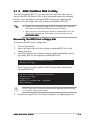
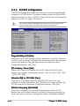
Managing and updating your BIOS ........................................ 4-1
4.1.1 Creating a bootable floppy disk .............................. 4-1
4.1.2 AFUDOS utility ........................................................ 4-2
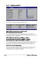
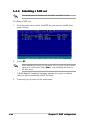
4.1.3 ASUS CrashFree BIOS 2 utility ................................ 4-5
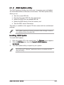
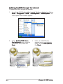
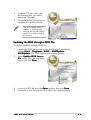
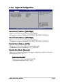
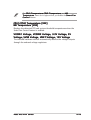
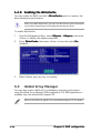
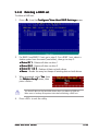
4.1.4 ASUS Update utility ................................................ 4-7
BIOS setup program ........................................................... 4-10
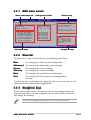
4.2.1 BIOS menu screen ................................................. 4-11
4.2.2 Menu bar ............................................................... 4-11
4.2.3 Navigation keys .................................................... 4-11
4.2.4 Menu items ........................................................... 4-12
4.2.5 Sub-menu items ................................................... 4-12
4.2.6 Configuration fields .............................................. 4-12
4.2.7 Pop-up window ..................................................... 4-12
4.2.8 Scroll bar .............................................................. 4-12
4.2.9 General help .......................................................... 4-12
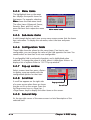
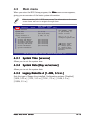
Main menu .......................................................................... 4-13
4.3.1 System Time ......................................................... 4-13
4.3.2 System Date ......................................................... 4-13
4.3.3 Legacy Diskette A ................................................ 4-13
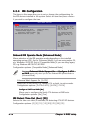
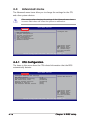
4.3.4 IDE Configuration .................................................. 4-14
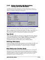
4.3.5 Primary/Secondary IDE Master/Slave,
Tertiary and Fourth IDE Master ............................ 4-15
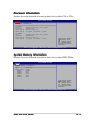
4.3.6 System Information .............................................. 4-16
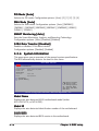
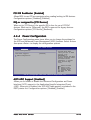
Advanced menu .................................................................. 4-18
4.4.1 CPU Configuration ................................................. 4-18
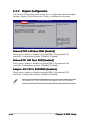
4.4.2 Chipset Configuration ........................................... 4-20
4.4.3 PCI/PnP Configuration .......................................... 4-22
4.4.4 Power Configuration ............................................. 4-23
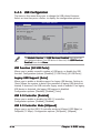
4.4.5 USB Configuration ................................................. 4-26
4.4.6 Super IO Configuration ......................................... 4-27
4.4.7 Hardware Monitor ................................................. 4-28
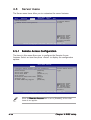
Server menu ....................................................................... 4-30
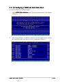
4.5.1 Remote Access Configuration .............................. 4-30
Contents
4.6
4.7
4.8
Security .............................................................................. 4-32
Boot menu .......................................................................... 4-35
4.7.1 Boot Device Priority .............................................. 4-35
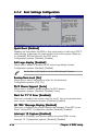
4.7.2 Boot Settings Configuration ................................. 4-36
Exit menu ........................................................................... 4-37
Chapter 5: RAID configuration
5.1
5.2
5.3
5.4
5.5
Setting up RAID .................................................................... 5-1
5.1.1 RAID definitions ...................................................... 5-1
5.1.2 Installing hard disk drives ....................................... 5-2
5.1.3 Setting the RAID item in BIOS ................................ 5-2
5.1.4 RAID configuration utilities ..................................... 5-3
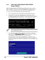
LSI Logic Embedded SATA RAID Setup Utility ...................... 5-4
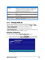
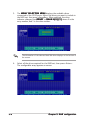
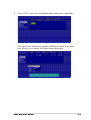
5.2.1 Creating a RAID set ................................................ 5-5
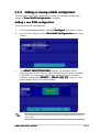
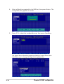
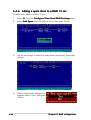
5.2.2 Adding or viewing a RAID configuration ............... 5-11
5.2.3 Initializing the logical drives .................................. 5-14
5.2.4 Rebuilding failed drives ......................................... 5-19
5.2.5 Checking the drives for data consistency ............ 5-21
5.2.6 Deleting a RAID configuration ............................... 5-24
5.2.7 Selecting the boot drive from a RAID set ............. 5-25
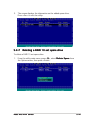
5.2.8 Enabling the WriteCache ...................................... 5-26
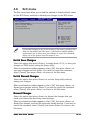
Global Array Manager ......................................................... 5-26
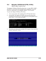
Adaptec SCSISelect(TM) Utility (NCLV-DS2 model only) ... 5-27
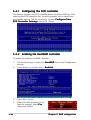
5.4.1 Configuring the SCSI controller ............................ 5-28
5.4.2 Enabling the HostRAID controller ......................... 5-28
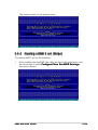
5.4.3 Creating a RAID 0 set (Stripe) .............................. 5-29
5.4.4 Creating a RAID 1 set (Mirror) .............................. 5-33
5.4.5 Creating a RAID 10 set (Stripe+Mirror) ................ 5-36
5.4.6 Adding a spare drive to a RAID 10 set ................. 5-40
5.4.7 Deleting a RAID 10 set spare drive ...................... 5-41
5.4.8 Deleting a RAID set ............................................... 5-43
5.4.9 Rebuilding a RAID set ........................................... 5-44
5.4.10 Verifying a RAID set hard disk drive ..................... 5-45
5.4.11 Making a RAID set bootable .................................. 5-46
Adaptec® RAID Configuration Utility
(NCLV-D2/SATA model only) ............................................. 5-48
5.5.1 Configuring the hard disk drive(s) ........................ 5-49
5.5.2 Creating a RAID 0 set (Striped) ............................ 5-50
5.5.3 Creating a RAID 0 set via Migrate ........................ 5-54
5.5.4 Creating a RAID 1 set (Mirrored) .......................... 5-56
v
Contents
5.5.5
5.5.6
5.5.7
5.5.8
5.5.9
5.5.10
Deleting a RAID 0 set ........................................... 5-59
Deleting a RAID 1 set ........................................... 5-60
Adding a spare drive to a RAID 1 set ................... 5-62
Deleting a RAID 1 spare drive ............................... 5-63
Rebuilding a RAID set ........................................... 5-64
Using the Disk Utilities .......................................... 5-66
Chapter 6: Driver installation
6.1
6.2
6.3
6.4
RAID driver installation ......................................................... 6-1
6.1.1 Creating a RAID driver disk ..................................... 6-1
6.1.2 Installing the RAID controller driver ........................ 6-3
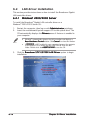
LAN driver installation ........................................................ 6-10
6.2.1 Windows® 2000/2003 Server .............................. 6-10
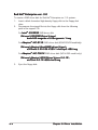
6.2.2 Red Hat® Enterprise ver. 3.0 ................................ 6-12
VGA driver installation ........................................................ 6-14
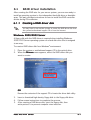
6.3.1 Windows® 2000 Server ........................................ 6-14
6.3.2 Windows® 2003 Server ........................................ 6-15
6.3.3 Red Hat® Enterprise ver. 3.0 ................................ 6-15
Management applications and utilities installation ............. 6-16
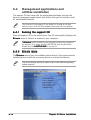
6.4.1 Running the support CD ....................................... 6-16
6.4.2 Drivers menu ........................................................ 6-16
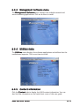
6.4.3 Management Software menu ................................ 6-17
6.4.4 Utilities menu ........................................................ 6-17
6.4.5 Contact information ............................................. 6-17
Appendix: Block diagrams
A.1
A.2
vi
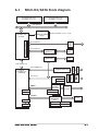
NCLV-D2/SATA block diagram ............................................. A-1
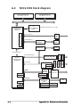
NCLV-DS2 block diagram ..................................................... A-2
Notices
Federal Communications Commission Statement
This device complies with Part 15 of the FCC Rules. Operation is subject to
the following two conditions:
• This device may not cause harmful interference, and
• This device must accept any interference received including interference
that may cause undesired operation.
This equipment has been tested and found to comply with the limits for a
Class B digital device, pursuant to Part 15 of the FCC Rules. These limits are
designed to provide reasonable protection against harmful interference in a
residential installation. This equipment generates, uses and can radiate radio
frequency energy and, if not installed and used in accordance with
manufacturer’s instructions, may cause harmful interference to radio
communications. However, there is no guarantee that interference will not
occur in a particular installation. If this equipment does cause harmful
interference to radio or television reception, which can be determined by
turning the equipment off and on, the user is encouraged to try to correct
the interference by one or more of the following measures:
• Reorient or relocate the receiving antenna.
• Increase the separation between the equipment and receiver.
• Connect the equipment to an outlet on a circuit different from that to
which the receiver is connected.
• Consult the dealer or an experienced radio/TV technician for help.
The use of shielded cables for connection of the monitor to the graphics
card is required to assure compliance with FCC regulations. Changes or
modifications to this unit not expressly approved by the party
responsible for compliance could void the user’s authority to operate
this equipment.
Canadian Department of Communications Statement
This digital apparatus does not exceed the Class B limits for radio noise
emissions from digital apparatus set out in the Radio Interference
Regulations of the Canadian Department of Communications.
This class B digital apparatus complies with Canadian
ICES-003.
vii
Safety information
Electrical safety
• To prevent electrical shock hazard, disconnect the power cable from the
electrical outlet before relocating the system.
• When adding or removing devices to or from the system, ensure that the
power cables for the devices are unplugged before the signal cables are
connected. If possible, disconnect all power cables from the existing
system before you add a device.
• Before connecting or removing signal cables from the motherboard,
ensure that all power cables are unplugged.
• Seek professional assistance before using an adapter or extension cord.
These devices could interrupt the grounding circuit.
• Make sure that your power supply is set to the correct voltage in your
area. If you are not sure about the voltage of the electrical outlet you are
using, contact your local power company.
• If the power supply is broken, do not try to fix it by yourself. Contact a
qualified service technician or your retailer.
Operation safety
• Before installing the motherboard and adding devices on it, carefully read
all the manuals that came with the package.
• Before using the product, make sure all cables are correctly connected
and the power cables are not damaged. If you detect any damage,
contact your dealer immediately.
• To avoid short circuits, keep paper clips, screws, and staples away from
connectors, slots, sockets and circuitry.
• Avoid dust, humidity, and temperature extremes. Do not place the
product in any area where it may become wet.
• Place the product on a stable surface.
• If you encounter technical problems with the product, contact a qualified
service technician or your retailer.
viii
About this guide
This user guide contains the information you need when installing and
configuring the motherboard.
How this guide is organized
This guide contains the following parts:
•
Chapter 1: Product introduction
This chapter describes the features of the motherboard and the new
technologies it supports.
•
Chapter 2: Hardware information
This chapter lists the hardware setup procedures that you have to
perform when installing system components. It includes description of
the switches, jumpers, and connectors on the motherboard.
•
Chapter 3: Powering up
This chapter describes the power up sequence and ways of shutting
down the system.
•
Chapter 4: BIOS setup
This chapter tells how to change system settings through the BIOS Setup
menus. Detailed descriptions of the BIOS parameters are also provided.
•
Chapter 5: RAID configuration
This chapter provides instructions for setting up, creating, and
configuring RAID sets using the available utilities.
•
Chapter 6: Driver installation
This chapter provides instructions for installing the necessary drivers
for various system components.
•
Appendix: Reference information
This appendix includes additional information that you may refer to
when configuring the motherboard.
Where to find more information
Refer to the following sources for additional information and for product
and software updates.
1.
ASUS websites
The ASUS website provides updated information on ASUS hardware
and software products. Refer to the ASUS contact information.
2.
Optional documentation
Your product package may include optional documentation, such as
warranty flyers, that may have been added by your dealer. These
documents are not part of the standard package.
ix
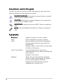
Conventions used in this guide
To make sure that you perform certain tasks properly, take note of the
following symbols used throughout this manual.
D A N G E R / W A R N I N G : Information to prevent injury to yourself
when trying to complete a task.
C A U T I O N : Information to prevent damage to the components
when trying to complete a task.
I M P O R T A N T : Instructions that you MUST follow to complete a
task.
N O T E : Tips and additional information to help you complete a
task.
Typography
Bold text
Indicates a menu or an item to select.
Italics
<Key>
Used to emphasize a word or a phrase.
Keys enclosed in the less-than and greaterthan sign means that you must press the
enclosed key.
Example: <Enter> means that you must press
the Enter or Return key.
<Key1+Key2+Key3>
If you must press two or more keys
simultaneously, the key names are linked with
a plus sign (+).
Example: <Ctrl+Alt+D>
Command
Means that you must type the command
exactly as shown, then supply the required
item or value enclosed in brackets.
Example: At the DOS prompt, type the
command line: format A:/S
x
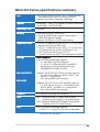
NCLV-D2 Series specifications summary
CPU
Dual 604-pin sockets for Intel® Xeon™ processors with
Extended Memory 64-bit Technology (EM64T)
Supports Intel® Hyper-Threading Technology
Chipset
Northbridge : Intel® E7320 Memory Controller Hub (MCH)
Southbridge : Intel® 6300ESB
Front Side Bus
800 MHz
Memory
Dual-channel memory architecture
6 x 240-pin DIMM sockets support registered ECC
DDR2-400 memory modules
Supports 256 MB up to 8 GB system memory
Expansion slots
1 x PCI-X 133 MHz/64-bit slot (PCI-X 1.0) (1U/2U riser)
(supports Zero-Channel RAID card)
1 x PCI-X 133 MHz/64-bit slot (PCI-X 1.0) (1U/2U riser)
1 x PCI Express x8 slot (x4 link, PCI Express 1.0a)
2 x PCI 33 MHz/32-bit/5V slot (PCI 2.3)
1 x mini-PCI socket for ASUS® Server Management Board
Storage
Both models:
Intel® 6300ESB Southbridge supports:
- 4 x Ultra DMA 100/66/33 devices
- 2 x SATA-150 HDDs with RAID 0 and RAID 1
configuration via the embedded LSI Logic
Embedded SATA RAID controller
NCLV-D2/SATA
Adaptec® AIC-8130 PCI-X SATAII controller supports:
- 4 x SATAII-300 HDDs with RAID 0, RAID 1, and
RAID 0+1 configurations
- Zero-Channel RAID card (optional)
NCLV-DS2
Adaptec® AIC-7901X PCI-X SCSI controller supports:
- 1 x SCSI channel for up to 15 SCSI devices and
RAID 0, RAID 1, and RAID 0+1 configurations
- Zero-Channel RAID card (optional)
Graphics
ATI® RAGE-XL PCI-based VGA controller
LAN
LAN 1: Broadcom BCM5721 Gigabit LAN controller
Complies with PCI Express 1.0a specifications
LAN 2: Broadcom BCM5705E PCI Gigabit LAN controller
Complies with PCI 2.3 specifications
USB
Intel® 6300ESB Southbridge supports:
- 4 USB 2.0/1.1 ports (2 in rear and 2 in front panel)
(continued on the next page)
xi
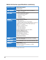
NCLV-D2 Series specifications summary
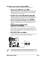
Special features
ASUS Smart Fan Control
ASUS CrashFree BIOS 2
ASUS MyLogo2
BIOS features
AMI BIOS, 8 MB Flash ROM, Green, PnP, DMI2.0a,
SMBIOS 2.3, WfM2.0
Rear panel
1 x PS/2 keyboard port (purple)
1 x PS/2 mouse port (green)
2 x USB 2.0/1.1 ports
1 x Serial port
1 x VGA port
2 x LAN (RJ-45) ports
Internal
connectors
Floppy disk drive connector
2 x IDE connectors
2 x Serial ATA connectors (both models)
4 x Serial ATA RAID connectors (NCLV-D2/SATA model only)
Ultra320 SCSI connector (NCLV-DS2 model only)
USB 2.0/1.1 connector
Serial port connector (COM2)
2 x CPU fan connectors
2 x front fan connectors
2 x rear fan connectors
Baseboard Management Connector (BMC)
Backplane SMBus connector
Power supply SMBus connector
Hard disk activity LED connector
24-pin SSI power connector
8-pin ATX 12V power connector
System panel connector
Auxiliary panel connector
Power
Requirement
SSI power supply (with 24-pin and 8-pin 12V plugs)
ATX 12V 2.0 compliant
Form Factor
E-ATX form factor: 12 in x 10.5 in (30.5 cm x 26.7 cm)
Support CD
contents
Device drivers
ASUS Live Update Utility
ASUS Server Web-based Management (ASWM)
Anti-virus software
*Specifications are subject to change without notice.
xii
This chapter describes the motherboard
features and the new technologies
it supports.
1
Product
introduction
Chapter summary
1
1.1
Welcome! .............................................................................. 1-1
1.2
Package contents ................................................................. 1-1
1.3
Special features .................................................................... 1-2
ASUS NCLV-D2 Series
1.1
Welcome!
T h a n k y o u f o r b u y i n g a n A S U S® N C L V - D 2 S e r i e s m o t h e r b o a r d !
The motherboard delivers a host of new features and latest technologies,
making it another standout in the long line of ASUS quality motherboards!
Before you start installing the motherboard, and hardware devices on it,
check the items in your package with the list below.
1.2
Package contents
Check your motherboard package for the following items.
Motherboard
ASUS NCLV-D2 Series motherboard
Cables
Serial ATA signal cables
• 2 pcs for NCLV-DS2 model
• 6 pcs for NCLV-D2/SATA model
Serial ATA power cable (dual-plug)
• 1 pc for NCLV-DS2 model
• 3 pcs for NCLV-D2/SATA model
SCSI Ultra320 cable ( N C L V - D S 2 m o d e l o n l y )
80-conductor IDE cable
3-in-1 floppy disk drive cable
Accessories
2 x CEK springs (for CPUs)
CPU heatsink support kit*
I/O shield
Application CDs
ASUS motherboard support CD (includes ASWM)
Documentation
NCLV-D2 Series user guide
ASWM 2.0 user guide
If any of the above items is damaged or missing, contact your retailer.
*
Refer to the CPU heatsink support kit documentation for installation
details.
ASUS NCLV-D2 Series
1-1
1.3
Special features
1.3.1
Product highlights
Latest processor technology
The motherboard comes with dual 604-pin surface mount ZIF sockets
designed for the Intel® Xeon™ processor with 800 MHz Front Side Bus
(FSB) and 1 MB L2 cache. The processor incorporates the Intel®
Hyper-Threading Technology, the Intel® NetBurst™ micro-architecture that
features hyper-pipelined technology, and Extended Memory 64-bit
Technology (EM64T). The EM64T enables the support for 64-bit operation
system, such as 64-bit Windows® and Linux. See page 2-10 for details.
Intel® E7320 and Intel® 6300ESB chipset
The Intel® E7320 Memory Controller Hub (MCH) and the Intel® 6300ESB
(I/O controller hub) provide the vital interfaces for the motherboard.
The MCH provides the processor, dual-channel DDR2-400 memory, and PCI
Express interfaces. The ICH is a new generation server class I/O controller
hub that provides the interface for PCI 2.3.
DDR2-400 memory support
The motherboard supports DDR2-400 memory which features data transfer
rates of 400 MHz to meet the higher bandwidth requirements of the latest
server applications. The dual-channel memory architecture doubles the
bandwidth of your system memory to boost system performance, eliminating
bottlenecks with peak bandwidths of up to 6.4 GB/s.
PCI Express™ interface
The motherboard fully supports PCI Express, the latest I/O interconnect
technology that speeds up the PCI bus. PCI Express features point-to-point
serial interconnections between devices and allows higher clockspeeds by
carrying data in packets. This high speed interface is software compatible with
existing PCI or PCI-X specifications. See page 2-19 for details.
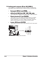
Ultra320 SCSI feature (NCLV-DS2 model only)
The Adaptec® AIC-7901X PCI-X SCSI controller is onboard to support one
68-pin Ultra320 SCSI connector, that can connect up to 15 SCSI devices.
See page 2-30 for details.
Serial ATA II feature (NCLV-D2/SATA model only)
The Adaptec® AIC-8130 SATA controller is onboard to support up to four
SATA II hard disk drives with RAID 0, RAID 1, and RAID 10 configurations.
The SATA II specification allows up to 300 MB/s data transfer rate.
See page 2-29 for details.
1-2
Chapter 1: Product introduction
Serial ATA technology
The motherboard supports the Serial ATA technology through the Serial ATA
interfaces controlled by the Intel® 6300ESB. The SATA specification allows
for thinner, more flexible cables with lower pin count, reduced voltage
requirement, and up to 150 MB/s data transfer rate.
Built-in SATA RAID solution
The Intel® 6300ESB allows RAID 0 and RAID 1 configuration for two SATA
connectors via the LSI Logic Embedded SATA RAID controller. See pages
2-28 and 5-4 for details.
Zero-Channel RAID (ZCR) solution
The motherboard comes with a 64-bit PCI-X slot for an optional
Zero-Channel RAID card. The Zero-Channel RAID card alows you to create all
types of RAID configurations for your storage devices. The ZCR capability
provides a cost-effective, reliable, and high-performance RAID solution. See
page 2-19 for details.
Gigabit LAN solution
The motherboard comes with dual Gigabit LAN controllers and ports to
provide a total solution for your networking needs. The onboard Broadcom®
BCM5721 and BCM5705E Gigabit LAN controllers use the PCI Express and
PCI interfaces, respectively, and have network throughput close to Gigabit
bandwidth. See page 2-26 for details.
USB 2.0 technology
The motherboard implements the Universal Serial Bus (USB) 2.0
specification, dramatically increasing the connection speed from the
12 Mbps bandwidth on USB 1.1 to a fast 480 Mbps on USB 2.0. USB 2.0 is
backward compatible with USB 1.1. See pages 2-26 and 2-31 for details.
Temperature, fan, and voltage monitoring
The CPU temperature is monitored by the ASIC (integrated in the Winbond
hardware monitor) to prevent overheating and damage. The system fan
rotations per minute (RPM) is monitored for timely failure detection. The
ASIC monitors the voltage levels to ensure stable supply of current for
critical components. See page 4-28 for details.
ASUS NCLV-D2 Series
1-3
1.3.2
Innovative ASUS features
CrashFree BIOS 2
This feature allows you to restore the original BIOS data from the support CD
in case when the BIOS codes and data are corrupted. This protection
eliminates the need to buy a replacement ROM chip. See page 4-5 for details.
ASUS Smart Fan Control technology
The ASUS Smart Fan Control technology smartly adjusts the fan speeds
according to the system loading to ensure quiet, cool, and efficient
operation. See page 4-28 for details.
ASUS MyLogo2™
This new feature present in the motherboard allows you to personalize and
add style to your system with customizable boot logos. See page 4-36 for
details.
1-4
Chapter 1: Product introduction
This chapter lists the hardware setup
procedures that you have to perform
when installing system components.
It includes description of the jumpers
and connectors on the motherboard.
2
Hardware
information
Chapter summary
2
2.1
Before you proceed .............................................................. 2-1
2.2
Motherboard overview .......................................................... 2-2
2.3
Central Processing Unit (CPU) ............................................ 2-10
2.4
System memory ................................................................. 2-14
2.5
Expansion slots ................................................................... 2-17
2.6
Jumpers .............................................................................. 2-20
2.7
Connectors ......................................................................... 2-26
ASUS NCLV-D2 Series
2.1
Before you proceed
Take note of the following precautions before you install motherboard
components or change any motherboard settings.
•
Unplug the power cord from the wall socket before touching any
component.
•
Use a grounded wrist strap or touch a safely grounded object or to
a metal object, such as the power supply case, before handling
components to avoid damaging them due to static electricity.
•
Hold components by the edges to avoid touching the ICs on them.
•
Whenever you uninstall any component, place it on a grounded
antistatic pad or in the bag that came with the component.
•
Before you install or remove any component, ensure
that the power supply is switched off or the power
c o r d i s d e t a c h e d f r o m t h e p o w e r s u p p l y . Failure to do so
may cause severe damage to the motherboard, peripherals, and/or
components.
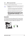
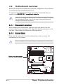
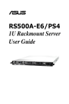
Onboard LED
The motherboard comes with a standby power LED. The green LED lights
up to indicate that the system is ON, in sleep mode, or in soft-off mode.
This is a reminder that you should shut down the system and unplug the
power cable before removing or plugging in any motherboard component.
The illustration below shows the location of the onboard LED.
SB_PWR1
ON
Standby
Power
OFF
Powered
Off
NCLV-D2 Series Onboard LED
ASUS NCLV-D2 Series
2-1
2.2
Motherboard overview
Before you install the motherboard, study the configuration of your chassis
to ensure that the motherboard fits into it.
To optimize the motherboard features, we highly recommend that you
install it in an S S I E E B 3 . 5 c o m p l i a n t c h a s s i ss.
Make sure to unplug the chassis power cord before installing or removing
the motherboard. Failure to do so can cause you physical injury and
damage motherboard components!
2.2.1
Placement direction
When installing the motherboard, make sure that you place it into the
chassis in the correct orientation. The edge with external ports goes to the
rear part of the chassis as indicated in the image below.
2.2.2
Screw holes
Place nine (9) screws into the holes indicated by circles to secure the
motherboard to the chassis.
Do not overtighten the screws! Doing so can damage the motherboard.
Place this side towards
the rear of the chassis
2-2
Chapter 2: Hardware information
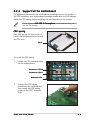
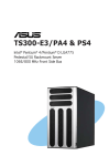
2.2.3
Support kit for motherboard
For additional protection from motherboard breakage due to the weight of
the CPU heatsinks, your motherboard package comes with two CEK springs.
Install the CEK spring before installing the motherboard to the chassis.
If your chassis is S S I E E B 3 . 5 c o m p l i a n tt, we recommend that you
use the CEK springs.
CEK spring
Each CEK spring has four hooks to
match the designated holes around
the CPU area.
Hook
To install the CEK spring:
1.
Locate the CPU heatsink holes
on the motherboard.
Socket for CPU2
Socket for CPU1
Heatsink hole
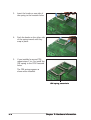
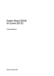
2.
Position the CEK spring
underneath the motherboard,
then match the CEK spring
hooks to the CPU1 heatsink
holes.
ASUS NCLV-D2 Series
2-3
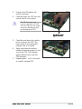
3.
Insert the hooks on one side of
the spring to the heatsink holes.
4.
Push the hooks on the other side
of the spring inward until they
snap in place.
5.
If you installed a second CPU,
repeat steps 2 to 4 to install the
CEK spring to the CPU2 heatsink
holes.
The CEK springs appear as
shown when installed.
CEK spring screw hole
2-4
Chapter 2: Hardware information
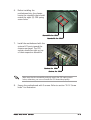
6.
Before installing the
motherboard into the chassis,
locate the standoffs that should
match the eight (8) CEK spring
screw holes.
Standoffs for CPU1
Standoffs for CPU2
7.
Install the motherboard with the
external I/O ports toward the
chassis rear panel. The CPU
sockets should be right on top
of their respective standoffs.
Socket for CPU1
Socket for CPU2
Make sure that the standoffs perfectly match the CEK spring screw
holes; otherwise, you can not install the CPU heatsinks properly.
8.
Secure the motherboard with 9 screws. Refer to section “2.2.2 Screw
holes” for illustration.
ASUS NCLV-D2 Series
2-5
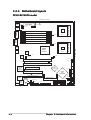
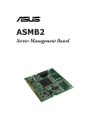
2.2.4
Motherboard layouts
NCLV-D2/SATA model
26.8cm (10.5in)
SSI12V1
SSIPWR1
REAR_FAN1
NCLV-D2/SATA
mPGA 604
PS/2KBMS
T: Mouse
KBPWR1
B: Keyboard
PSUSMB1
USB12
USBPW12
COM1
DDR2 DDR_B3 (64 bit,240-pin module)
DDR2 DDR_A3 (64 bit,240-pin module)
FM_CPU1
DDR2 DDR_B2 (64 bit,240-pin module)
CPU1
DDR2 DDR_A2 (64 bit,240-pin module)
VGA
DDR2 DDR_B1 (64 bit,240-pin module)
CPU_FAN1
LAN1
Intel
LAN2
MCH
E7320
Gigabit
LAN
BCM5721
CPU2
30.5cm (12in)
mPGA 604
DDR2 DDR_A1 (64 bit,240-pin module)
LAN_EN1
Gigabit
LAN
BCM5705E
FM_CPU2
REAR_FAN2
CPU_FAN2
PCIX1 (64-bit PCI-X)
FRNT_FAN1
PCIX2 (64-bit PCI-X)
ATI
RAGE XL
VGA
Controller
Adaptec
AIC-8130
PCIE1(x4 link)
Intel
PCI4 (32-bit 5V PCI)
SB_PWR1
CLRTC1
2-6
ICH
6300ESB
RECOVERY1
SATA1
PCI5 (32-bit 5V PCI)
Super
I/O
8Mbit
Flash
BIOS
SATA2
VGA_EN1
SATA_RAID1 SATA_RAID2 SATA_RAID3 SATA_RAID4
FRNT_FAN2
SATA_EN1
LAN_EN2
USB34
BMCSOCKET1
CR2032 3V
Lithium Cell
CMOS Power
HDLED1
AUX_PANEL1
BMCCONN1
SEC_IDE1
PRI_IDE1
BPSMB1
FLOPPY1
USBPW34
8130 LED1
LPT1
COM2
PANEL1
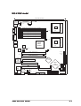
Chapter 2: Hardware information
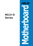
NCLV-DS2 model
26.8cm (10.5in)
SSI12V1
SSIPWR1
REAR_FAN1
NCLV-DS2
mPGA 604
PS/2KBMS
T: Mouse
KBPWR1
B: Keyboard
PSUSMB1
USB12
USBPW12
COM1
DDR2 DDR_B3 (64 bit,240-pin module)
DDR2 DDR_A3 (64 bit,240-pin module)
FM_CPU1
DDR2 DDR_B2 (64 bit,240-pin module)
CPU1
DDR2 DDR_A2 (64 bit,240-pin module)
VGA
DDR2 DDR_B1 (64 bit,240-pin module)
CPU_FAN1
LAN1
Intel
LAN2
MCH
E7320
Gigabit
LAN
BCM5721
CPU2
30.5cm (12in)
mPGA 604
DDR2 DDR_A1 (64 bit,240-pin module)
LAN_EN1
Gigabit
LAN
BCM5705E
FM_CPU2
REAR_FAN2
CPU_FAN2
PCIX1 (64-bit PCI-X)
FRNT_FAN1
FRNT_FAN2
SCSI1
SCSI_EN1
LAN_EN2
PCIX2 (64-bit PCI-X)
Adaptec
AIC-7901X
PCIE1(x4 link)
VGA_EN1
Intel
PCI4 (32-bit 5V PCI)
SB_PWR1
CLRTC1
SATA1
PCI5 (32-bit 5V PCI)
Super
I/O
8Mbit
Flash
BIOS
ICH
6300ESB
RECOVERY1
USB34
BMCSOCKET1
CR2032 3V
Lithium Cell
CMOS Power
SATA2
ATI
RAGE XL
VGA
Controller
HDLED1
AUX_PANEL1
BMCCONN1
SEC_IDE1
PRI_IDE1
BPSMB1
USBPW34
FLOPPY1
LPT1
COM2
ASUS NCLV-D2 Series
PANEL1
2-7
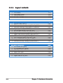
2.2.5
Layout contents
Slots/Sockets
Page
1.
CPU sockets
2-10
2.
DDR2 DIMM sockets
2-14
3.
PCI/PCI-X/PCI Express slots
2-19
4.
Zero-Channel RAID socket
2-19
Jumpers
1.
Clear RTC RAM (CLRTC1)
2-20
2.
CPU fan pin selection (3-pin FM_CPU1, FM_CPU2)
2-21
3.
USB device wake-up (3-pin USBPW12, USBPW34)
2-21
4.
Keyboard power (3-pin KBPWR1)
2-22
5.
VGA controller setting (3-pin VGA_EN1)
2-22
6.
Gigabit LAN controller setting (3-pin LAN1_EN1)
2-23
7.
Gigabit LAN controller setting (3-pin LAN2_EN1)
2-23
8.
SCSI controller setting (3-pin SCSI_EN1)
2-24
9.
SATA controller setting (3-pin SATA_EN1)
2-24
10. Adaptec 8130 LED setting (3-pin LED1)
2-25
11. Force BIOS recovery setting (3-pin RECOVERY1)
2-25
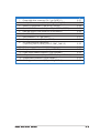
Rear panel connectors
2-8
Page
Page
1.
PS/2 mouse port (green)
2-26
2.
PS/2 keyboard port (purple)
2-26
3.
USB 2.0 ports 1 and 2
2-26
4.
Serial (COM1) port
2-26
5.
VGA port
2-26
6.
Gigabit LAN (RJ-45) ports
2-26
Chapter 2: Hardware information
Internal connectors
Page
1.
Floppy disk drive connector (34-1 pin FLOPPY1)
2-27
2.
Primary IDE connectors (40-1 pin PRI_IDE, SEC_IDE)
2-27
3.
Serial ATA connectors (7-pin SATA1, SATA2)
2-28
4.
Serial ATA RAID connectors (two 68-pin SCSIA1, SCSIB1)
2-29
5.
Hard disk activity LED connector (4-pin HDLED1)
2-29
6.
Ultra320 SCSI connectors
2-30
7.
USB connector (10-1 pin USB34)
2-31
8.
Serial port connector (10-1 pin COM2)
2-31
9.
CPU and system fan connectors
(3-pin CPU_FAN1/2, REAR_FAN1/2, FRNT_FAN1/2)
2-32
10. BMC connector (16-pin BMCCONN1)
2-32
11. Backplane SMBus connector (6-1 pin BPSMB1)
2-33
12. Power supply SMBus connector (5-pin PSUSMB1)
2-33
13. ATX power connectors (24-pin ATXPWR1, 8-pin ATX12V1)
2-34
14. System panel connector (20-pin PANEL1)
2-35
15. Auxiliary panel connector (20-pin AUX_PANEL1)
2-36
ASUS NCLV-D2 Series
2-9
2.3
Central Processing Unit (CPU)
The motherboard comes with surface mount 604-pin Zero Insertion Force
(ZIF) sockets. The sockets are designed for the Intel® Xeon™ processor in
the 604-pin package with 1 MB L2 cache. The new generation Xeon™
processor supports 800 MHz system bus and Extended Memory 64-bit
Technology (EM64T).
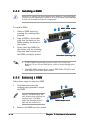
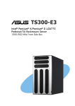
2.3.1
Installling the CPU
To install a CPU:
1.
Locate the CPU sockets on the motherboard.
CPU1
Intel Xeon
CPU2
Gold Arrow
Pin A1
NCLV-D2 Series CPU Socket 604
If installing only one CPU, use the socket CPU1.
2.
Flip up the socket lever and push
it all the way to the other side.
Make sure that the socket
lever is pushed back all the
way, otherwise the CPU does
not fit in completely.
Socket for CPU1
2-10
Chapter 2: Hardware information
3.
Position the CPU above the
socket as shown.
4.
Carefully insert the CPU into the
socket until it fits in place.
The CPU fits only in one
correct orientation. DO NOT
force the CPU into the socket
to prevent bending the pins
and damaging the CPU!
Marked corner
(gold arrow)
5.
Carefully push down the socket
lever to secure the CPU. The
lever clicks on the side tab to
indicate that it is locked.
6.
Apply the thermal interface
material (thermal grease) to the
top of the CPU. This thermal
grease should come with the
CPU package.
7.
Repeat steps 1 to 6 if you wish
to install a second CPU.
ASUS NCLV-D2 Series
2-11
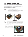
2.3.2
Installing the CPU heatsink and fan
The Intel® Xeon™ processors require an Intel certified heatsink and fan
assembly to ensure optimum thermal condition and performance.
When you buy a boxed Intel CPU, the package includes the heatsink, fan,
retention brackets, screws, thermal grease, installation manual, and other
items that are necessary for CPU installation.
•
Make sure that you have applied the thermal grease to the top of
the CPU before installing the heatsink and fan.
•
Refer to the installation manual that came with the CPU package for
details on heatsink/fan assembly and installation.
CPU heatsink (top view)
CPU heatsink (bottom view)
Heatsink screw
Before installing the CPU heatsinks, ensure that the jumpers FM_CPU1
and FM_CPU2 are set correctly depending on the pin definition of your
CPU fan cables. Refer to page 2-21 for information on these jumpers.
To install the CPU heatsink and fan:
1.
2-12
Place the heatsink on top of the
installed CPU, making sure that
the four screws on the heatsink
align with the nuts on the
support plate.
Chapter 2: Hardware information
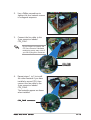
2.
Use a Phillips screwdriver to
tighten the four heatsink screws
in a diagonal sequence.
3.
Connect the fan cable to the
4-pin connector labeled
CPU_FAN1.
Do not forget to connect the
CPU fan connector! Hardware
monitoring errors may occur if
you fail to plug this connector.
CPU_FAN1
connector
4.
Repeat steps 1 to 3 to install
the other heatsink if you have
installed a second CPU, then
connect the fan cable to the
4-pin connector labeled
CPU_FAN2.
The heatsinks appear as shown
when installed.
CPU_FAN2 connector
ASUS NCLV-D2 Series
2-13
2.4
System memory
2.4.1
Overview
The motherboard comes with six Double Data Rate II (DDR2) Dual Inline
Memory Modules (DIMM) sockets to support 240-pin DDR modules.
The figure illustrates the location of the DDR DIMM sockets:
128 Pins
112 Pins
DDR_B3
DDR_A3
DDR_B2
DDR_A2
DDR_B1
DDR_A1
NCLV-D2 Series 240-pin DDR2 DIMM sockets
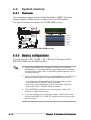
2.4.2
Memory configurations
You may install 256 MB, 512 MB, 1 GB, 2 GB, and 4 GB registered ECC
DDR2-400 DIMMs into the DIMM sockets.
•
Always install DIMMs with the same CAS latency. For optimum
compatibility, it is recommended that you obtain memory modules
from the same vendor. Refer to the DDR2 Qualified Vendors List at
the ASUS web site.
•
Due to chipset resource allocation, and depending on the number of
expansion cards installed, the following conditions may occur:
- the system may detect less than 8 GB system memory when
you installed four 2 GB DDR2 memory modules
- may show an available memory space of less than 4 GB when
you installed four 1 GB DDR2 memory modules
2-14
•
Three DDR DIMMs intalled into any three memory sockets will
function in single-channel mode.
•
If you are installing only one memory module, install into the blue
socket labeled DDR_A3 or DDR_B3. Installing into any other socket
would not work.
Chapter 2: Hardware information
Mode
DDR_B3 DDR_A3 DDR_B2 DDR_A2 DDR-B1
(blue)
(blue)
(black)
(black) (black)
DDR_A1
(black)
Single-channel
Dual-channel
Populated with DIMM
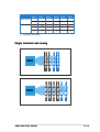
Single and dual rank mixing
Dual Rank DIMM B2
Dual Rank DIMM A3
Dual Rank DIMM B3
Single Rank DIMM A1
Single Rank DIMM B1
Single Rank DIMM A2
Single Rank DIMM B2
ASUS NCLV-D2 Series
Dual Rank DIMM B3
Dual Rank DIMM A2
MCH
Dual Rank DIMM A3
MCH
2-15
2.4.3
Installing a DIMM
Make sure to unplug the power supply before adding or removing DIMMs
or other system components. Failure to do so may cause severe damage
to both the motherboard and the components.
2
To install a DIMM:
3
1.
Unlock a DIMM socket by
pressing the retaining clips
outward.
2.
Align a DIMM on the socket
such that the notch on the
DIMM matches the break on
the socket.
3.
DDR2 DIMM notch
1
Firmly insert the DIMM into
the socket until the retaining
clips snap back in place and
the DIMM is properly seated.
Unlocked retaining clip
2.4.4
•
A DDR2 DIMM is keyed with a notch so that it fits in only one
direction. Do not force a DIMM into a socket to avoid damaging the
DIMM.
•
The DDR2 DIMM sockets do not support DDR DIMMs. DO NOT install
DDR DIMMs to the DDR2 DIMM sockets.
Removing a DIMM
Follow these steps to remove a DIMM.
1.
Simultaneously press the
retaining clips outward to unlock
the DIMM.
2
Support the DIMM lightly with
your fingers when pressing the
retaining clips. The DIMM
might get damaged when it
flips out with extra force.
2.
2-16
1
1
DDR2 DIMM notch
Remove the DIMM from the socket.
Chapter 2: Hardware information
2.5
Expansion slots
In the future, you may need to install expansion cards. The following
sub-sections describe the slots and the expansion cards that they support.
Make sure to unplug the power cord before adding or removing
expansion cards. Failure to do so may cause you physical injury and
damage motherboard components.
2.5.1
Installing an expansion card
To install an expansion card:
1.
Before installing the expansion card, read the documentation that
came with it and make the necessary hardware settings for the card.
2.
Remove the system unit cover (if your motherboard is already
installed in a chassis).
3.
Remove the bracket opposite the slot that you intend to use. Keep
the screw for later use.
4.
Align the card connector with the slot and press firmly until the card is
completely seated on the slot.
5.
Secure the card to the chassis with the screw you removed earlier.
6.
Replace the system cover.
2.5.2
Configuring an expansion card
After installing the expansion card, configure the it by adjusting the
software settings.
1.
Turn on the system and change the necessary BIOS settings, if any.
See Chapter 4 for information on BIOS setup.
2.
Assign an IRQ to the card. Refer to the tables on the next page.
3.
Install the software drivers for the expansion card.
When using PCI cards on shared slots, ensure that the drivers support
“Share IRQ” or that the cards do not need IRQ assignments. Otherwise,
conflicts will arise between the two PCI groups, making the system
unstable and the card inoperable.
ASUS NCLV-D2 Series
2-17
2.5.3
Interrupt assignments
Standard interrupt assignments
IRQ
Priority
0
1
2
3
4
5
6
7
8
9
10
11
12
13
14
15
1
2
—
11
12
13
14
15
3
4
5
6
7
8
9
10
Standard Function
System Timer
Keyboard Controller
Re-direct to IRQ#9
Communications Port (COM2)*
Communications Port (COM1)*
IRQ holder for PCI steering*
Floppy Disk Controller
Printer Port (LPT1)*
System CMOS/Real Time Clock
IRQ holder for PCI steering*
IRQ holder for PCI steering*
IRQ holder for PCI steering*
PS/2 Compatible Mouse Port*
Numeric Data Processor
Primary IDE Channel
Secondary IDE Channel
* These IRQs are usually available for ISA or PCI devices.
PCI Bus Number, IDSEL, and IRQ assignments
Description
INTA
IDE Controller
PIRQC#
SATA Controller
PIRQC#
SMBus Controller
PIRQB#
USB UHCI Controller #1
PIRQA#
USB UHCI Controller #2
PIRQD#
USB 2.0 EHCI Controller
PIRQH#
INTB
AIC7901 SCSI controller
INTC
INTD
PXIRQ2#
REQ#
GNT#
X_REQ3#
X_GNT3#
ATI RAGE XL
PIRQB#
REQ2#
GNT2#
PCIX Slot 1
PXIRQ0#
PXIRQ1#
PXIRQ2#
PXIRQ3#
X_IRQ0#
X_IRQ0#
PCIX Slot 2
PXIRQ3#
PXIRQ1#
PXIRQ0#
PXIRQ2#
X_IRQ1#
X_IRQ1#
PCI Express Slot3
2-18
PCIX Slot 4
PIRQE#
PIRQF#
PIRQG#
PIRQH#
REQ0#
GNT0#
PCIX Slot 5
PIRQG#
PIRQH#
PIRQE#
PIRQF#
REQ1#
GNT1#
Chapter 2: Hardware information
2.5.4
PCI/PCI-X slots
The PCI/PCI-X slots support cards
such as a LAN card, SCSI card, USB
card, and other cards that comply
with PCI 2.3 and PCI-X 1.0
specifications. The figure shows a
RAID card installed on a PCI-X slot.
32-bit PCI slot
64-bit PCI-X slot
2.5.5
PCI Express x8 slot
The onboard PCI Express x8 slot
provides x4 link to the MCH. This slot
is designed for various server class
high performance add-on cards like
SCSI RAID card, fiber-channel card,
etc.
2.5.6
ZCR slot
The 64-bit PCI-X slot (green) on the motherboard supports a Zero-Channel
RAID card that allows all types of RAID configurations.
ASUS NCLV-D2 Series
2-19
2.6
Jumpers
The grayed out components in the illustrations may not be present in
certain models.
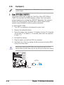
1.
Clear RTC RAM (CLRTC1)
This jumper allows you to clear the Real Time Clock (RTC) RAM in
CMOS. You can clear the CMOS memory of date, time, and system
setup parameters by erasing the CMOS RTC RAM data. The onboard
button cell battery powers the RAM data in CMOS, which include
system setup information such as system passwords.
To erase the RTC RAM:
1. Turn OFF the computer and unplug the power cord.
2. Remove the onboard battery.
3. Move the jumper cap from pins 1-2 (default) to pins 2-3. Keep the
cap on pins 2-3 for about 5~10 seconds, then move the cap back
to pins 1-2.
4. Re-install the battery.
5. Plug the power cord and turn ON the computer.
6. Hold down the <Del> key during the boot process and enter BIOS
setup to re-enter data.
Except when clearing the RTC RAM, never remove the cap on CLRTC
jumper default position. Removing the cap will cause system boot failure!
CLRTC1
2 1
Normal
(Default)
3 2
Clear CMOS
NCLV-D2 Series Clear RTC RAM
2-20
Chapter 2: Hardware information
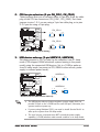
2.
CPU fan pin selection (3-pin FM_CPU1, FM_CPU2)
These jumpers allow you to connect either a 3-pin or a 4-pin fan cable
plug to the CPU fan connectors (CPU_FAN1, CPU_FAN2). Set these
jumpers to pins 1-2 if you are using a 3-pin fan cable plug, or to pins
2-3 if you are using a 4-pin plug.
FM_CPU1
2 3
1 2
DC mode
(Default)
PWM
FM_CPU2
2 1
3 2
DC mode
(Default)
PWM
NCLV-D2 Series FM_CPU Setting
3.
USB device wake-up (3-pin USBPW12, USBPW34)
Set these jumpers to +5V to wake up the computer from S1 sleep
mode (CPU stopped, DRAM refreshed, system running in low power
mode) using the connected USB devices. Set to +5VSB to wake up
from S4 sleep mode (no power to CPU, DRAM in slow refresh, power
supply in reduced power mode).
USBPW12
1 2
2 3
+5V
(Default)
+5VSB
USBPW34
1 2
+5V
(Default)
2 3
+5VSB
NCLV-D2 Series USB device wake-up
•
The USB device wake-up feature requires a power supply that can
provide 500mA on the +5VSB lead for each USB port; otherwise, the
system would not power up.
•
If you are using Windows 2000, you need to install Service Pack 4 to
wake up the system from S4 sleep mode.
•
The total current consumed must NOT exceed the power supply
capability (+5VSB) whether under normal condition or in sleep mode.
ASUS NCLV-D2 Series
2-21
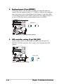
4.
Keyboard power (3-pin KBPWR1)
This jumper allows you to enable or disable the keyboard wake-up
feature. Set this jumper to pins 2-3 (+5VSB) to wake up the computer
when you press a key on the keyboard (the default is the Space Bar).
This feature requires an ATX power supply that can supply at least 1A
on the +5VSB lead, and a corresponding setting in the BIOS.
KBPWR1
1 2
2 3
+5V
(Default)
+5VSB
NCLV-D2 Series Keyboard power setting
5.
VGA controller setting (3-pin VGA_EN1)
These jumpers allow you to enable or disable the onboard ATI®
RAGE-XL PCI VGA controller. Set to pins 1-2 to activate the VGA
feature.
VGA_EN1
1
2
NCLV-D2 Series VGA Setting
2-22
2
3
Enable
(Default)
Disable
Chapter 2: Hardware information
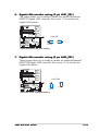
6.
Gigabit LAN controller setting (3-pin LAN1_EN1)
This jumper allows you to enable or disable the onboard Broadcom®
BCM5721 Gigabit LAN1 controller. Set to pins 1-2 to activate the
Gigabit LAN feature.
LAN_EN1
2 1
Enable
(Default)
3 2
Disable
NCLV-D2 Series LAN_EN1 setting
7.
Gigabit LAN controller setting (3-pin LAN2_EN1)
These jumpers allow you to enable or disable the onboard Broadcom®
BCM5705E Gigabit LAN2 controller. Set to pins 1-2 to activate the
Gigabit LAN feature.
LAN_EN2
2
1
Enable
(Default)
3
2
Disable
NCLV-D2 Series LAN_EN2 setting
ASUS NCLV-D2 Series
2-23
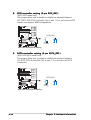
8.
SCSI controller setting (3-pin SCSI_EN1)
(NCLV-DS2 model only)
This jumper allows you to enable or disable the onboard Adaptec®
AIC-7901X SCSI U320 controller. Set to pins 1-2 to activate the SCSI
feature, and support RAID configurations.
SCSI_EN1
1
2
2
3
Enable
(Default)
Disable
NCLV-D2 Series SCSI setting
9.
SATA controller setting (3-pin SATA_EN1)
(NCLV-D2/SATA model only)
This jumper allows you to enable or disable the onboard Adaptec®
AIC-8130 SATA II controller. Set to pins 1-2 to activate the SATA
connectors.
SATA_EN1
1
2
2
3
Enable
(Default)
Disable
NCLV-D2 Series SATA setting
2-24
Chapter 2: Hardware information
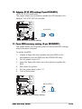
1 0 . Adaptec 8130 LED setting (3-pin 8130LED1)
(NCLV-D2/SATA model only)
This jumper allows you to enable or disable the LED related to the
Adaptec® AIC-8130 SATA-II controller.
8130 LED1
1 2
Disable
(Default)
2 3
Enable
NCLV-D2 Series 8130 LED setting
1 1 . Force BIOS recovery setting (3-pin RECOVERY1)
This jumper allows you to quickly update or recover the BIOS settings
when it becomes corrupted.
To update the BIOS:
1.
Prepare a floppy disk that contains the latest BIOS for the
motherboard (xxxx-xxx.ROM) and the AFUDOS.EXE utility.
2.
Set the jumper to pins 2-3.
3.
Insert the floppy disk then turn on the system to update the
BIOS.
4.
Shut down the system.
5.
Set the jumper back to pins 1-2.
6.
Turn on the system.
RECOVERY1
1
2
Normal
(Default)
2
3
BIOS Recovery
NCLV-D2 Series BIOS recovery setting
ASUS NCLV-D2 Series
2-25
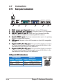
2.7
Connectors
2.7.1
Rear panel connectors
1
2
1.
2.
3.
4.
5.
6.
7.
3
4
5
6
7
P S / 2 m o u s e p o r t ( g r e e n ) . This port is for a PS/2 mouse.
P S / 2 k e y b o a r d p o r t ( p u r p l e ) . This port is for a PS/2 keyboard.
U S B 2 . 0 p o r t s 1 a n d 2 . These two 4-pin Universal Serial Bus
(USB) ports are available for connecting USB 2.0 devices.
S e r i a l ( C O M 1 ) p o r tt. This 9-pin communication port is for pointing
devices or other serial devices.
V G A p o r t . This port is for a VGA monitor or other VGA-compatible
devices.
G i g a b i t L A N 1 ( R J - 4 5 ) p o r t . This ports allow Gigabit connection
to a Local Area Network (LAN) through a network hub. Refer to the
table below for the LAN port LED indications.
G i g a b i t L A N 2 ( R J - 4 5 ) p o r t . This ports allow Gigabit connection
to a Local Area Network (LAN) through a network hub. Refer to the
table below for the LAN port LED indications.
LAN port LED indications
ACT/LINK LED
Status
Description
Status
Description
OFF
No link
OFF
10 Mbps connection
GREEN
Linked
ORANGE 100 Mbps connection
BLINKING Data activity
2-26
SPEED LED
GREEN
1000 Mbps connection
ACT/LINK S P E E D
LED
LED
LAN port
Chapter 2: Hardware information
2.7.2
1.
Internal connectors
Floppy disk drive connector (34-1 pin FLOPPY)
This connector is for the provided floppy disk drive (FDD) signal cable.
Insert one end of the cable to this connector, then connect the other
end to the signal connector at the back of the floppy disk drive.
Pin 5 on the connector is removed to prevent incorrect cable connection
when using a FDD cable with a covered Pin 5.
FLOPPY
PIN 1
NOTE: Orient the red markings on
the floppy ribbon cable to PIN 1.
NCLV-D2 Series Floppy disk drive connector
2.
IDE connectors (40-1 pin PRI_IDE1, SEC_IDE1)
These connectors are for an Ultra DMA 100/66 signal cable. The Ultra
DMA 100/66 signal cable has three connectors: a blue connector for
the primary IDE connector on the motherboard, a black connector for
an Ultra DMA 100/66 IDE slave device (optical drive/hard disk drive),
and a gray connector for an Ultra DMA 100/66 IDE master device (hard
disk drive). If you install two hard disk drives, you must configure the
second drive as a slave device by setting its jumper accordingly. Refer
to the hard disk documentation for the jumper settings.
•
Pin 20 on the IDE connector is removed to match the covered hole
on the Ultra DMA cable connector. This prevents incorrect insertion
when you connect the IDE cable.
•
Use the 80-conductor IDE cable for Ultra DMA 100/66 IDE devices.
SEC_IDE1
PIN 1
PRI_IDE1
PIN 1
NOTE: Orient the red markings
(usually zigzag) on the IDE
ribbon cable to PIN 1.
NCLV-D2 Series IDE connectors
ASUS NCLV-D2 Series
2-27
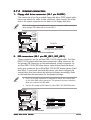
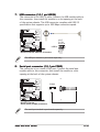
3.
Serial ATA connectors (7-pin SATA1, SATA2)
These connectors are for the Serial ATA signal cables for Serial ATA
hard disk drives.
If you installed Serial ATA hard disk drives, you can create a RAID 0 or
RAID 1 set LSI Logic Embedded SATA RAID in the Intel® 6300ESB
Southbridge chip.
These connectors are set to S t a n d a r d I D E mode by default. In
S t a n d a r d I D E mode, you can connect Serial ATA boot/data hard disk
drives to these connectors. If you intend to create a Serial ATA RAID set
using these connectors, set the C o n f i g u r e S
S-- A T A a s R A I D item in
the BIOS to [Yes]. See section “4.3.4 IDE Configuration” for details.
SATA2
GND
RSATA_TXP2
RSATA_TXN2
GND
RSATA_RXP2
RSATA_RXN2
GND
SATA1
GND
RSATA_TXP1
RSATA_TXN1
GND
RSATA_RXP1
RSATA_RXN1
GND
NCLV-D2/SATA SATA connectors
SATA2
GND
RSATA_TXP2
RSATA_TXN2
GND
RSATA_RXP2
RSATA_RXN2
GND
SATA1
GND
RSATA_TXP1
RSATA_TXN1
GND
RSATA_RXP1
RSATA_RXN1
GND
NCLV-DS2 SATA connectors
Important notes on Serial ATA
2-28
•
You must install Windows® 2000 Service Pack 4 or the Windows® XP
Service Pack 1 before using Serial ATA hard disk drives. The Serial
ATA RAID feature (RAID 0 or RAID 1) is available only if you are
using Windows® 2000/XP.
•
Use only two Serial ATA RAID connectors for each RAID 0 or RAID 1 set.
•
When using the connectors in Standard IDE mode, connect the primary
(boot) hard disk drive to the SATA1 connector. Refer to the table on the
next page for recommended SATA hard disk drive connections.
Chapter 2: Hardware information
Serial ATA hard disk drive connection
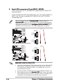
4.
Connector
Setting
Use
SATA1
Master
Boot disk
SATA2
Slave
Data disk
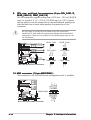
Serial ATA RAID connectors (7-pin SATA_RAID1,
SATA_RAID2, SATA_RAID3, SATA_RAID4)
(NCLV-D2/SATA model only)
These connectors are for the Serial ATA signal cables. These
connectors support up to four SATA hard disk drives that you can
configure as an array through the onboard Adaptec® AIC-8130 PCI-X
SATAII controller.
SATA_RAID1 SATA_RAID2
GND
RSATA_TXP1
RSATA_TXN1
GND
RSATA_RXP1
RSATA_RXN1
GND
GND
RSATA_TXP2
RSATA_TXN2
GND
RSATA_RXP2
RSATA_RXN2
GND
SATA_RAID3 SATA_RAID4
GND
RSATA_TXP1
RSATA_TXN1
GND
RSATA_RXP1
RSATA_RXN1
GND
GND
RSATA_TXP2
RSATA_TXN2
GND
RSATA_RXP2
RSATA_RXN2
GND
NCLV-D2 Series SATA RAID connectors
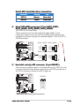
5.
Hard disk activity LED connector (4-pin HDLED1)
This connector supplies power to the hard disk activity LED. The read
or write activities of any device connected to the SCSI connectors or
the SATA connectors cause this LED to light up.
HDLED1
SCSI_ACTLED+
SCSI_ACTLEDSCSI_ACTLEDSCSI_ACTLED+
1
NCLV-D2 Series
SCSI/SATA card activity LED connector
ASUS NCLV-D2 Series
2-29
6.
Ultra320 SCSI connector (68-pin SCSI1)
(NCLV-D2/SATA model only)
This motherboard comes with the Adaptec® AIC-7901X PCI-X SCSI
controller that supports one 68-Pin Ultra320 SCSI connector. The SCSI
channel can support a maximum of 15 SCSI devices as specified by
Ultra320 standards.
SCSI1
68-Pin Ultra320/
Ultra2-Wide SCSI Connector
NCLV-D2 Series Onboard SCSI connector
1 35
34 68
SCSI Connection Notes
This motherboard has a 68-Pin Ultra320 SCSI connector.
The onboard SCSI chipset incorporates an advanced multimode I/O cell
that supports both single-ended (SE), Ultra2, Ultra160, and Ultra320
devices. With Ultra320 devices, the SCSI bus platform performs at full
Ultra320 speeds (up to 320 MB/s) and extended cabling 12m (or
25m in a point-to-point configuration). When an SE device is attached,
the bus defaults to an SE speed and 1.5m cable length.
Connect SCSI devices as specified. A SCSI channel should have only one
type of SCSI standard (e.g. Ultra320, Ultra160, Ultra2, Ultra-Wide).
Mixing SCSI devices on a single channel decreases performance of the
slower device.
2-30
Chapter 2: Hardware information
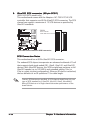
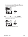
7.
USB connector (10-1 pin USB34)
USB+5V
USB_P6USB_P6+
GND
NC
This connector is for USB 2.0 ports. Connect the USB module cable to
this connector, then install the module to a slot opening at the back
of the system chassis. This USB connector complies with USB 2.0
specification that supports up to 480 Mbps connection speed.
NCLV-D2 Series USB 2.0 connector
USB+5V
USB_P5USB_P5+
GND
USB34
The USB port module is purchased separately.
8.
Serial port connector (10-1 pin COM2)
This connector is for a serial (COM) port. Connect the serial port
module cable to this connector, then install the module to a slot
opening at the back of the system chassis.
COM2
PIN 1
NCLV-D2 Series
Serial port2 (COM2) connector
The serial port module is purchased separately.
ASUS NCLV-D2 Series
2-31
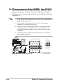
9.
CPU, rear, and front fan connectors (3-pin CPU_FAN1/2,
REAR_FAN1/2, FRNT_FAN1/2)
The fan connectors support cooling fans of 350 mA ~ 740 mA (8.88 W
max.) or a total of 2.1 A ~ 4.44 A (53.28 W max.) at +12V. Connect
the fan cables to the fan connectors on the motherboard, making sure
that the black wire of each cable matches the ground pin of the
connector.
Do not forget to connect the fan cables to the fan connectors.
Insufficient air flow inside the system may damage the motherboard
components. These are not jumpers! Do not place jumper caps on the
fan connectors!
Rotation
+12V
GND
REAR_FAN2
REAR_FAN2
GND
+12V
Rotation
REAR_FAN1
REAR_FAN1
CPU_FAN1
FANOUT4
CPU_FAN2
GND
FANPWR2
FANOUT4
CPU_FAN1
GND
FANPWR2
CPU_FAN2
FRNT_FAN1
FRNT_FAN2
Rotation
+12V
GND
Rotation
+12V
GND
FRNT_FAN1
FRNT_FAN2
NCLV-D2 Series Fan connectors
1 0 . BMC connector (16-pin BMCCONN1)
+5VSB
+5VSB
BMC SMBCLK
12CCLK1
PSON#
BMC_RST#
PWROK
PSONEN#
This connector is for the ASUS server management card, if available.
NCLV-D2 Series BMC connector
2-32
+5VSB
+5VSB
BMC SMBDATA
12CDATA1
FP_PWRBTN#
BMC_PRESENT#
BMC_SMI#
GND
BMCCONN1
Chapter 2: Hardware information
1 1 . Backplane SMBus connector (6-1 pin BPSMB1)
This connector allows you to connect SMBus (System Management
Bus) devices. Devices communicate with an SMBus host and/or other
SMBus devices using the SMBus interface.
BPSMB1
NCLV-D2 Series SMBus connector
GND
I2C_6_DATA#
+5V
NC
I2C_6_CLK#
1
PSU_I2CCLK
PSU_I2CDATA
NC
GND
+3.3V Remote Sense
1 2 . Power supply SMBus connector (5-pin PSUSMB1)
This connector is for the power supply SMB cable, if your power
supply supports the SMBus function.
PSUSMB1
NCLV-D2 Series Power supply SMBus connector
ASUS NCLV-D2 Series
2-33
1 3 . A T X power connectors (24-pin ATXPWR1, 8
8-- p i n A T X 1 2 V 1
1))
These connectors are for SSI power supply plugs. The power supply
plugs are designed to fit these connectors in only one orientation.
Find the proper orientation and push down firmly until the connectors
completely fit.
•
Use of an SSI 12 V Specification 2.0-compliant power supply unit
(PSU) that provides a minimum power of 600 W is recommended for
a fully-configured system.
•
Do not forget to connect the 8-pin ATX +12 V power plug;
otherwise, the system will not boot up.
•
Use of a PSU with a higher power output is recommended when
configuring a system with more power consuming devices. The
system may become unstable or may not boot up if the power is
inadequate.
•
You must install a PSU with a higher power rating if you intend to
install additional devices.
NCLV-D2 Series Power connectors
2-34
GND
GND
GND
GND
8-pin
+12V CPU
+12V CPU
+12V CPU
+12V CPU
1
+3 Volts
-12 Volts
Ground
PSON#
Ground
Ground
Ground
-5 Volts
+5 Volts
+5 Volts
+5 Volts
Ground
+3 Volts
+3 Volts
Ground
+5 Volts
Ground
+5 Volts
Ground
Power OK
+5V Standby
+12 Volts
+12 Volts
+3 Volts
24-pin Power Connector
For Power Supply
with 20-pin
Power Connector
Chapter 2: Hardware information
1 4 . System panel connector (20-pin PANEL1)
This connector supports several chassis-mounted functions.
System power LED (Green 3-pin PLED)
This 3-pin connector is for the system power LED. Connect the
chassis power LED cable to this connector. The system power
LED lights up when you turn on the system power, and blinks
when the system is in sleep mode.
•
Hard disk drive activity LED (Red 2-pin IDE_LED)
This 2-pin connector is for the HDD Activity LED. Connect the
HDD Activity LED cable to this connector. The IDE LED lights up
or flashes when data is read from or written to the HDD.
•
System warning speaker (Orange 4-pin SPEAKER)
This 4-pin connector is for the chassis-mounted system warning
speaker. The speaker allows you to hear system beeps and
warnings.
•
ATX power button/soft-off button
(Light Green 2-pin PWRSW)
This connector is for the system power button. Pressing the
power button turns the system on or puts the system in sleep or
soft-off mode depending on the BIOS settings. Pressing the
power switch for more than four seconds while the system is ON
turns the system OFF.
•
Reset button (Blue 2-pin RESET)
This 2-pin connector is for the chassis-mounted reset button for
system reboot without turning off the system power.
POWERLED+
GND
POWERLEDMLED+
MLEDNC
+5V
GND
GND
SPKROUT
•
NCLV-D2 Series System panel connector
NMIBTN#
GND
POWERBTN#
GND
NC
RESETBTN#
GND
HDLED+
HDLED-
PANEL1
The system panel connector is color-coded for easy connection.
ASUS NCLV-D2 Series
2-35
1 5 . Auxiliary panel connector (20-pin AUX_PANEL1)
This connector is for additional front panel features including front
panel SMB, locator LED and switch, chassis intrusion, and LAN LEDs.
•
LAN activity LED (2-pin LAN1_LED, LAN2_LED)
These leads are for Gigabit LAN activity LEDs on the front panel.
•
Chassis intrusion (4-1 pin CHASSIS)
These leads are for the intrusion detection feature for chassis
with intrusion sensor or microswitch. When you remove any
chassis component, the sensor triggers and sends a high-level
signal to these leads to record a chassis intrusion event.
•
Locator LED (6-pin LOCATOR)
These leads are for the locator switch and LED on the front panel.
GND
I2C_4_DATA#
+3V
LAN1_LINKACTLED+
LAN1_LINKACTLEDLAN2_LINKACTLEDLAN2_LINKACTLED+
Front panel SMB (6-1 pin FPSMB)
These leads connect the front panel SMBus cable.
NC
I2C_4_CLK#
•
CASEOPEN
GND
LOCATORLED1+
LOCATORLED1LOCATORBTN#
GND
LOCATORLED2LOCATORLED2+
PIN1
+5VSB
AUX_PANEL1
NCLV-D2 Series Auxiliary panel connector
2-36
Chapter 2: Hardware information
This chapter describes the power up
sequence, and ways of shutting down
the system.
3
Powering up
Chapter summary
3
3.1
Starting up for the first time ................................................ 3-1
3.2
Powering off the computer .................................................. 3-2
ASUS NCLV-D2 Series
3.1
Starting up for the first time
1.
After making all the connections, replace the system case cover.
2.
Be sure that all switches are off.
3.
Connect the power cord to the power connector at the back of the
system chassis.
4.
Connect the power cord to a power outlet that is equipped with a
surge protector.
5.
Turn on the devices in the following order:
a. Monitor
b. External SCSI devices (starting with the last device on the chain)
c. System power
6.
After applying power, the system power LED on the system front
panel case lights up. For systems withATX power supplies, the system
LED lights up when you press the ATX power button. If your monitor
complies with “green” standards or if it has a “power standby”
feature, the monitor LED may light up or switch between orange and
green after the system LED turns on.
The system then runs the power-on self tests or POST. While the
tests are running, the BIOS beeps (see BIOS beep codes table below)
or additional messages appear on the screen. If you do not see
anything within 30 seconds from the time you turned on the power,
the system may have failed a power-on test. Check the jumper
settings and connections or call your retailer for assistance.
AMI BIOS beep codes
7.
Beep Description
Error
One beep
Keyboard controller error
Refresh Time error
No master drive detected
Two continuous beeps followed by
two short beeps
Floppy controller failure
Two continuous beeps followed by
four short beeps
Hardware component failure
At power on, hold down the <Delete> key to enter the BIOS Setup.
Follow the instructions in Chapter 4.
ASUS NCLV-D2 Series
3-1
3.2
Powering off the computer
3.2.1
Using the OS shut down function
If you are using Windows® 2000:
2.
Click the S t a r t button then click S h u t D o w n . . .
Make sure that the S h u t D o w n option button is selected, then click
the O K button to shut down the computer.
3.
The power supply should turn off after Windows® shuts down.
1.
If you are using Windows® XP:
2.
Click the S t a r t button then select T u r n O f f C o m p u t e r .
Click the T u r n O f f button to shut down the computer.
3.
The power supply should turn off after Windows® shuts down.
1.
3.2.2
Using the dual function power switch
While the system is ON, pressing the power switch for less than four
seconds puts the system to sleep mode or to soft-off mode, depending on
the BIOS setting. Pressing the power switch for more than four seconds
lets the system enter the soft-off mode regardless of the BIOS setting.
Refer to section “4.4.4 Power Configuration” in Chapter 4 for details.
3-2
Chapter 3: Powering up
This chapter tells how to change
the system settings through the BIOS
Setup menus. Detailed descriptions
of the BIOS parameters are also
provided.
4
BIOS setup
Chapter summary
4
4.1
Managing and updating your BIOS ........................................ 4-1
4.2
BIOS setup program ........................................................... 4-10
4.3
Main menu .......................................................................... 4-13
4.4
Advanced menu .................................................................. 4-18
4.5
Server menu ....................................................................... 4-30
4.6
Security .............................................................................. 4-32
4.7
Boot menu .......................................................................... 4-35
ASUS NCLV-D2 Series
4.1
Managing and updating your BIOS
The following utilities allow you to manage and update the motherboard
Basic Input/Output System (BIOS) setup.
1.
2.
3.
A S U S A F U D O S (Updates the BIOS in DOS mode using a bootable
floppy disk.)
A S U S C r a s h F r e e B I O S 2 (Updates the BIOS using a bootable
floppy disk or the motherboard support CD when the BIOS file fails or
gets corrupted.)
A S U S U p d a t e (Updates the BIOS in Windows® environment.)
Refer to the corresponding sections for details on these utilities.
Save a copy of the original motherboard BIOS file to a bootable floppy
disk in case you need to restore the BIOS in the future. Copy the original
motherboard BIOS using the ASUS Update or AFUDOS utilities.
4.1.1
1.
Creating a bootable floppy disk
Do either one of the following to create a bootable floppy disk.
DOS environment
a. Insert a 1.44MB floppy disk into the drive.
b. At the DOS prompt, type format A:/S then press <Enter>.
Windows® XP environment
a. Insert a 1.44 MB floppy disk to the floppy disk drive.
b. Click S t a r t from the Windows® desktop, then select M y
C o m p u t e rr.
c. Select the 3 1/2 Floppy Drive icon.
d. Click F i l e from the menu, then select F o r m a tt. A F o r m a t 3 1 / 2
F l o p p y D i s k window appears.
e. W i n d o w s® X P u s e r s : Select C r e a t e a n M S - D O S s t a r t u p
d i s k from the format options field, then click S t a r tt.
2.
Copy the original or the latest motherboard BIOS file to the bootable
floppy disk.
ASUS NCLV-D2 Series
4-1
4.1.2
AFUDOS utility
The AFUDOS utility allows you to update the BIOS file in DOS environment
using a bootable floppy disk with the updated BIOS file. This utility also
allows you to copy the current BIOS file that you can use as backup when
the BIOS fails or gets corrupted during the updating process.
Copying the current BIOS
To copy the current BIOS file using the AFUDOS utility:
•
Make sure that the floppy disk is not write-protected and has at
least 1024 KB free space to save the file.
•
The succeeding BIOS screens are for reference only. The actual BIOS
screen displays may not be same as shown.
1.
Copy the AFUDOS utility (afudos.exe) from the motherboard support
CD to the bootable floppy disk you created earlier.
2.
Boot the system in DOS mode, then at the prompt type:
afudos /o[filename]
where the [filename] is any user-assigned filename not more than
eight alphanumeric characters for the main filename and three
alphanumeric characters for the extension name.
A:\>afudos /oOLDBIOS1.rom
Main filename
3.
Extension name
Press <Enter>. The utility copies the current BIOS file to the floppy
disk.
A:\>afudos /oOLDBIOS1.rom
AMI Firmware Update Utility - Version 1.19(ASUS V2.07(03.11.24BB))
Copyright (C) 2002 American Megatrends, Inc. All rights reserved.
Reading flash ..... done
Write to file...... ok
A:\>
The utility returns to the DOS prompt after copying the current BIOS
file.
4-2
Chapter 4: BIOS setup
Updating the BIOS file
To update the BIOS file using the AFUDOS utility:
1.
Visit the ASUS website (www.asus.com) and download the latest BIOS
file for the motherboard. Save the BIOS file to a bootable floppy disk.
Write the BIOS filename on a piece of paper. You need to type the exact
BIOS filename at the DOS prompt.
2.
Copy the AFUDOS utility (afudos.exe) from the motherboard support
CD to the bootable floppy disk you created earlier.
3.
Boot the system in DOS mode, then at the prompt type:
afudos /i[filename]
where [filename] is the latest or the original BIOS file on the bootable
floppy disk.
A:\>afudos /iNCLVDS2.rom
Use the appropriate BIOS file depending on your motherboard model
(e.g. NCLVD2SATA.ROM or NCLVDS2.ROM)
4.
The utility verifies the file and starts updating the BIOS.
A:\>afudos /iNCLVDS2.ROM
AMI Firmware Update Utility - Version 1.19(ASUS V2.07(03.11.24BB))
Copyright (C) 2002 American Megatrends, Inc. All rights reserved.
WARNING!! Do not turn off power during flash BIOS
Reading file ....... done
Reading flash ...... done
Advance Check ......
Erasing flash ...... done
Writing flash ...... 0x0008CC00 (9%)
Do not shut down or reset the system while updating the BIOS to
prevent system boot failure!
ASUS NCLV-D2 Series
4-3
5.
The utility returns to the DOS prompt after the BIOS update process is
completed. Reboot the system from the hard disk drive.
A:\>afudos /iNCLVDS2.ROM
AMI Firmware Update Utility - Version 1.19(ASUS V2.07(03.11.24BB))
Copyright (C) 2002 American Megatrends, Inc. All rights reserved.
WARNING!! Do not turn off power during flash BIOS
Reading file ....... done
Reading flash ...... done
Advance Check ......
Erasing flash ...... done
Writing flash ...... done
Verifying flash .... done
Please restart your computer
A:\>
4-4
Chapter 4: BIOS setup
4.1.3
ASUS CrashFree BIOS 2 utility
The ASUS CrashFree BIOS 2 is an auto recovery tool that allows you to
restore the BIOS file when it fails or gets corrupted during the updating
process. You can update a corrupted BIOS file using the motherboard
support CD or the floppy disk that contains the updated BIOS file.
•
Prepare the motherboard support CD or the floppy disk containing
the updated motherboard BIOS before using this utility.
•
Make sure that you rename the original or updated BIOS file in the
floppy disk according the exact name of your motherboard, e.g.
NCLVDS2.ROM
M.
Recovering the BIOS from a floppy disk
To recover the BIOS from a floppy disk:
1.
Turn on the system.
2.
Insert the floppy disk with the original or updated BIOS file to the
floppy disk drive.
3.
The utility displays the following message and automatically checks
the floppy disk for the original or updated BIOS file.
Bad BIOS checksum. Starting BIOS recovery...
Checking for floppy...
When found, the utility reads the BIOS file and starts flashing the
corrupted BIOS file.
Bad BIOS checksum. Starting BIOS recovery...
Checking for floppy...
Floppy found!
Reading file “NCLVDS2.ROM”. Completed.
Start flashing...
DO NOT shut down or reset the system while updating the BIOS! Doing
so can cause system boot failure!
4.
Restart the system after the utility completes the updating process.
ASUS NCLV-D2 Series
4-5
Recovering the BIOS from the support CD
To recover the BIOS from the support CD:
1.
Remove any floppy disk from the floppy disk drive, then turn on the
system.
2.
Insert the support CD to the optical drive.
3.
The utility displays the following message and automatically checks
the floppy disk for the original or updated BIOS file.
Bad BIOS checksum. Starting BIOS recovery...
Checking for floppy...
When no floppy disk is found, the utility automatically checks the
optical drive for the original or updated BIOS file. The utility then
updates the corrupted BIOS file.
Bad BIOS checksum. Starting BIOS recovery...
Checking for floppy...
Floppy not found!
Checking for CD-ROM...
CD-ROM found!
Reading file “NCLVDS2.ROM”. Completed.
Start flashing...
DO NOT shut down or reset the system while updating the BIOS! Doing
so can cause system boot failure!
4.
Restart the system after the utility completes the updating process.
The recovered BIOS may not be the latest BIOS version for this
motherboard. Visit the ASUS website (www.asus.com) to download the
latest BIOS file.
4-6
Chapter 4: BIOS setup
4.1.4
ASUS Update utility
The ASUS Update is a utility that allows you to manage, save, and update
the motherboard BIOS in Windows® environment. The ASUS Update utility
allows you to:
• Save the current BIOS file
• Download the latest BIOS file from the Internet
• Update the BIOS from an updated BIOS file
• Update the BIOS directly from the Internet, and
• View the BIOS version information.
This utility is available in the support CD that comes with the motherboard
package.
ASUS Update requires an Internet connection either through a network
or an Internet Service Provider (ISP).
Installing ASUS Update
To install ASUS Update:
1.
2.
3.
Place the support CD in the optical drive. The D r i v e r s menu appears.
Click the U t i l i t i e s tab, then click I n s t a l l A S U S U p d a t e
VX.XX.XX
X.
The ASUS Update utility is copied to your system.
Quit all Microsoft® Windows® applications before you update the BIOS
using this utility.
ASUS NCLV-D2 Series
4-7
Updating the BIOS through the Internet
To update the BIOS through the Internet:
4-8
1.
Launch the ASUS Update utility from the Windows® desktop by clicking
Start > Programs > ASUS > ASUSUpdate > ASUSUpdate
e. The
ASUS Update main window appears.
2.
Select U p d a t e B I O S f r o m
t h e I n t e r n e t option from the
drop-down menu, then click
N e x tt.
3.
Select the ASUS FTP site
nearest you to avoid network
traffic, or click A u t o S e l e c tt.
Click N e x tt.
Chapter 4: BIOS setup
4.
From the FTP site, select the
BIOS version that you wish to
download. Click Next.
5.
Follow the screen instructions to
complete the update process.
The ASUS Update utility is
capable of updating itself
through the Internet. Always
update the utility to avail all
its features.
Updating the BIOS through a BIOS file
To update the BIOS through a BIOS file:
1.
2.
Launch the ASUS Update utility from the Windows® desktop by
clicking S t a r t > P r o g r a m s > A S U S > A S U S U p d a t e >
ASUSUpdate
e. The ASUS Update main window appears.
Select U p d a t e B I O S f r o m a
f i l e option from the drop-down
menu, then click N e x tt.
3.
Locate the BIOS file from the O p e n window, then click S a v e
e.
4.
Follow the screen instructions to complete the update process.
ASUS NCLV-D2 Series
4-9
4.2
BIOS setup program
This motherboard supports a programmable firmware chip that you can
update using the provided utility described in section “4.1 Managing and
updating your BIOS.”
Use the BIOS Setup program when you are installing a motherboard,
reconfiguring your system, or prompted to “Run Setup”. This section
explains how to configure your system using this utility.
Even if you are not prompted to use the Setup program, you can change
the configuration of your computer in the future. For example, you can
enable the security password feature or change the power management
settings. This requires you to reconfigure your system using the BIOS
Setup program so that the computer can recognize these changes and
record them in the CMOS RAM of the firmware hub.
The firmware hub on the motherboard stores the Setup utility. When you
start up the computer, the system provides you with the opportunity to
run this program. Press <Del> during the Power-On-Self-Test (POST) to
enter the Setup utility; otherwise, POST continues with its test routines.
If you wish to enter Setup after POST, restart the system by pressing
<Ctrl+Alt+Delete>, or by pressing the reset button on the system chassis.
You can also restart by turning the system off and then back on. Do this
last option only if the first two failed.
The Setup program is designed to make it as easy to use as possible. Being
a menu-driven program, it lets you scroll through the various sub-menus
and make your selections from the available options using the navigation
keys.
4-10
•
The default BIOS settings for this motherboard apply for most
conditions to ensure optimum performance. If the system becomes
unstable after changing any BIOS settings, load the default settings
to ensure system compatibility and stability. Select the L o a d
S e t u p D e f a u l t s item under the Exit Menu. See section “4.8 Exit
Menu.”
•
The BIOS setup screens shown in this section are for reference
purposes only, and may not exactly match what you see on your
screen.
•
Visit the ASUS website (www.asus.com) to download the latest BIOS
file for this motherboard.
Chapter 4: BIOS setup
4.2.1
BIOS menu screen
Menu items Menu bar
Main
Advanced
Server
Configuration fields
BIOS SETUP UTILITY
Security
Boot
General help
Exit
System Overview
System Time
System Date
[11:10:19]
[Thu 04/21/2005]
Legacy Diskette A
[1.44M, 3.5 in]
IDE Configuration
Primary IDE Master
Primary IDE Slave
Secondary IDE Master
Secondary IDE Slave
Tertiary IDE Master
Fourth IDE Master
[Not
[Not
[Not
[Not
[Not
[Not
Detected]
Detected]
Detected]
Detected]
Detected]
Detected]
System Information
Use [ENTER]. [TAB],
or [SHIFT-TAB] to
select a field.
Use [+] or [-] to
configure system time.
Select Screen
Select Item
+- Change Option
F1 General Help
F10 Save and Exit
ESC Exit
v02.58 (C)Copyright 1985-2004, American Megatrends, Inc.
Sub-menu items
4.2.2
Navigation keys
Menu bar
The menu bar on top of the screen has the following main items:
Main
Advanced
For changing the basic system configuration
Server
Security
For changing the server settings
Boot
Exit
For changing the system boot configuration
For changing the advanced system settings
For changing the security settings
For selecting the exit options and loading default
settings
To select an item on the menu bar, press the right or left arrow key on the
keyboard until the desired item is highlighted.
4.2.3
Navigation keys
At the bottom right corner of a menu screen are the navigation keys for
that particular menu. Use the navigation keys to select items in the menu
and change the settings.
Some of the navigation keys differ from one screen to another.
ASUS NCLV-D2 Series
4-11
4.2.4
Menu items
The highlighted item on the menu
bar displays the specific items for
that menu. For example, selecting
M a i n shows the Main menu items.
The other items (Advanced, Server,
Security, Boot, and Exit) on the
menu bar have their respective menu
items.
4.2.5
Main
Advanced
Server
BIOS SETUP UTILITY
Security
Boot
System Time
System Date
Exit
[11:10:19]
[Thu 04/21/2005]
Legacy Diskette A
[1.44M, 3.5 in]
IDE Configuration
Primary IDE Master
Primary IDE Slave
Secondary IDE Master
Secondary IDE Slave
Teritary IDE Master
Fourth IDE Master
: [Not
: [Not
: [Not
: [Not
: [Not
: [Not
Detected]
Detected]
Detected]
Detected]
Detected]
Detected]
System Information
Use [ENTER], [TAB],
or [SHIFT-TAB] to
select a field.
Use [+] or [-] to
configure system
time.
Select Screen
Select Item
Change Option
General Help
Save and Exit
Exit
+F1
F10
ESC
Main menu items
Sub-menu items
A solid triangle before each item on any menu screen means that the iteam
has a sub-menu. To display the sub-menu, select the item and press
<Enter>.
4.2.6
Configuration fields
These fields show the values for the menu items. If an item is userconfigurable, you can change the value of the field opposite the item. You
cannot select an item that is not user-configurable.
A configurable field is enclosed in brackets, and is highlighted when
selected. To change the value of a field, select it then press <Enter> to
display a list of options. Refer to “4.2.7 Pop-up window.”
4.2.7
Pop-up window
BIOS SETUP UTILITY
Advanced
APM Configuration
Select a menu item then press <Enter>
to display a pop-up window with the
configuration options for that item.
4.2.8
Scroll bar
Power Management/APM
Video Power Down Mode
Hard Disk Power Down Mode
Suspend Time Out(Minute)
Throttle Slow Clock Ratio
[Enabled]
[Suspend]
[Suspend]
[Disabled]
[50%]
Power Button Function
Restore on AC Power Loss
[On/Off]
[Power Off]
Power
Power
Power
Power
Power
[Disabled]
[Disabled]
[Disabled]
[Disabled]
[Disabled]
On
On
On
On
On
by PS/2 Keyboard
by PS/2 Mouse
Ring
PME#
RTC Alarm
Use [ENTER], [TAB],
or [SHIFT-TAB] to
select a field.
Use [+] or [-] to
configure system
time.
+F1
F10
ESC
Select Screen
Select Item
Change Option
General Help
Save and Exit
Exit
A scroll bar appears on the right side
Pop-up window
of a menu screen when there are items
Scroll bar
that do not fit on the screen. Press the
Up/Down arrow keys or <Page Up> /
<Page Down> keys to display the other items on the screen.
4.2.9
General help
At the top right corner of the menu screen is a brief description of the
selected item.
4-12
Chapter 4: BIOS setup
4.3
Main menu
When you enter the BIOS Setup program, the M a i n menu screen appears,
giving you an overview of the basic system information.
Refer to section “4.2.1 BIOS menu screen” for information on the menu
screen items and how to navigate through them.
Main
Advanced
Server
BIOS SETUP UTILITY
Security
Boot
Exit
System Overview
System Time
System Date
[11:10:19]
[Thu 04/21/2005]
Legacy Diskette A
[1.44M, 3.5 in]
IDE Configuration
Primary IDE Master
Primary IDE Slave
Secondary IDE Master
Secondary IDE Slave
Tertiary IDE Master
Fourth IDE Master
[Not
[Not
[Not
[Not
[Not
[Not
Detected]
Detected]
Detected]
Detected]
Detected]
Detected]
System Information
Use [ENTER]. [TAB],
or [SHIFT-TAB] to
select a field.
Use [+] or [-] to
configure system time.
Select Screen
Select Item
+- Change Option
F1 General Help
F10 Save and Exit
ESC Exit
v02.58 (C)Copyright 1985-2004, American Megatrends, Inc.
4.3.1
System Time [xx:xx:xx]
Allows you to set the system time.
4.3.2
System Date [Day xx/xx/xxxx]
Allows you to set the system date.
4.3.3
Legacy Diskette A [1.44M, 3.5 in.]
Sets the type of floppy drive installed. Configuration options: [Disabled]
[360K, 5.25 in.] [1.2M , 5.25 in.] [720K , 3.5 in.] [1.44M, 3.5 in.]
[2.88M, 3.5 in.]
ASUS NCLV-D2 Series
4-13
4.3.4
IDE Configuration
The items in this menu allow you to set or change the configurations for
the IDE devices installed in the system. Select an item then press <Enter>
if you wish to configure the item.
BIOS SETUP UTILITY
Main
IDE Configuration
Onboard IDE Operate Mode
Enhanced Mode Support On
Configure S-ATA as RAID
IDE Detect Time Out (Sec)
[Enhanced Mode]
[S-ATA]
[No]
[35]
Set [Compatible Mode]
when Legacy OS (i.e.
WIN ME, 98, NT4.0, MS
DOS) is used.
Set [enhanced Mode]
when native OS (i.e.
WIN2000, WIN XP) is
used.
Select Screen
Select Item
+- Change Option
F1 General Help
F10 Save and Exit
ESC Exit
v02.58 (C)Copyright 1985-2004, American Megatrends, Inc.
Onboard IDE Operate Mode [Enhanced Mode]
Allows selection of the IDE operation mode depending on the installed
operating system (OS). Set to [Enhanced Mode] if you are using native OS,
e.g. Windows® 2000/XP. Set to [Compatible Mode] if you are using legacy
OS, e.g. Windows ME/98/NT, MS-DOS.
Configuration options: [Compatible Mode] [Enhanced Mode]
The items E n h a n c e d M o d e S u p p o r t O n and C o n f i g u r e S - A T A
a s R A I D appear only when you set the Onboard IDE Operate Mode to
[Enhanced Mode].
Enhanced Mode Support On [S-ATA]
Allows you to set Serial ATA, Parallel ATA, or both, to native mode.
Configuration options: [P-ATA+S-ATA] [S-ATA] [ P-ATA]
Configure S-ATA as RAID [No]
Allows you to configure the Serial ATA devices as RAID sets.
Configuration options: [No] [Yes]
IDE Detect Time Out (Sec) [35]
Selects the time our value (in seconds) for detecting ATA/ATAPI devices.
Configuration options: [0] [5] [10] [15] [20] [25] [30] [35]
4-14
Chapter 4: BIOS setup
4.3.5
Primary/Secondary IDE Master/Slave,
Tertiary and Fourth IDE Master
The BIOS automatically detects the connected IDE devices. There is a
separate sub-menu for each IDE device. Select a device item, then press
<Enter> to display the IDE device information.
BIOS SETUP UTILITY
Main
Primary IDE Master
Device
: Hard Disk
Vendor
: ST320413A
Size
: 20.0GB
LBA Mode
: Supported
Block Mode
: 16 Sectors
PIO Mode
: Supported
Async DMA
: MultiWord DMA-2
Ultra DMA
: Ultra DMA-5
SMART Monitoring: Supported
Type
LBA/Large Mode
Block(Multi-sector Transfer)
PIO Mode
DMA Mode
SMART Monitoring
32Bit Data Transfer
[Auto]
[Auto]
[Auto]
[Auto]
[Auto]
[Auto]
[Disabled]
Select the type of
device connected to
the system.
Select Screen
Select Item
+- Change Option
F1 General Help
F10 Save and Exit
ESC Exit
v02.58 (C)Copyright 1985-2004, American Megatrends, Inc.
The BIOS automatically detects the values opposite the dimmed items
(Device, Vendor, Size, LBA Mode, Block Mode, PIO Mode, Async DMA, Ultra
DMA, and SMART monitoring). These values are not user-configurable.
These items show N/A if no IDE device is installed in the system.
Type [Auto]
Selects the type of IDE drive. Setting to [Auto] allows automatic selection
of the appropriate IDE device type. Select [CDROM] if you are specifically
configuring a CD-ROM drive. Select [ARMD] (ATAPI Removable Media
Device) if your device is either a ZIP, LS-120, or MO drive.
Configuration options: [Not Installed] [Auto] [CDROM] [ARMD]
LBA/Large Mode [Auto]
Enables or disables the LBA mode. Setting to [Auto] enables the LBA mode
if the device supports this mode, and if the device was not previously
formatted with LBA mode disabled. Configuration options: [Disabled]
[Auto]
Block (Multi-sector Transfer) [Auto]
Enables or disables data multi-sectors transfers. When set to [Auto], the
data transfer from and to the device occurs multiple sectors at a time if
the device supports multi-sector transfer feature. When set to [Disabled],
the data transfer from and to the device occurs one sector at a time.
Configuration options: [Disabled] [Auto]
ASUS NCLV-D2 Series
4-15
PIO Mode [Auto]
Selects the PIO mode. Configuration options: [Auto] [0] [1] [2] [3] [4]
DMA Mode [Auto]
Selects the DMA mode. Configuration options: [Auto] [SWDMA0]
[SWDMA1] [SWDMA2] [MWDMA0] [MWDMA1] [MWDMA2] [UDMA0]
[UDMA1] [UDMA2]
SMART Monitoring [Auto]
Sets the Smart Monitoring, Analysis, and Reporting Technology.
Configuration options: [Auto] [Disabled] [Enabled]
32Bit Data Transfer [Disabled]
Enables or disables 32-bit data transfer.
Configuration options: [Disabled] [Enabled]
4.3.6
System Information
This menu gives you an overview of the general system specifications.
The BIOS automatically detects the items in this menu.
BIOS SETUP UTILITY
Main
System Information
Model Name
Model ID
ASUS NCLV-D2/SATA
8001A0
ASUS-BIOS
Version
Date
1001.003
03/16/2005
Processor
System Memory
Select Screen
Select Item
+- Change Option
F1 General Help
F10 Save and Exit
ESC Exit
v02.58 (C)Copyright 1985-2004, American Megatrends, Inc.
Model Name
Displays the auto-detected ASUS motherboard model (either
NCLV-D2/SATA, or NCLV-DS2).
Model ID
Displays the auto-detected identification number of the motherboard.
ASUS BIOS
Displays the auto-detected BIOS version in the motherboard.
4-16
Chapter 4: BIOS setup
Processor Information
Displays the auto-detected information about the installed CPU or CPUs.
BIOS SETUP UTILITY
Main
Processor Information
*** CPU1 :
Brand
ID/uCode
Ratio Value
Cache Value
Intel(R) Xeon(TM) CPU 3.60GHz
0F34h/014h
Actual 18 Max 18
L1//16KB L2/1024KB L3/0KB
*** CPU2 :
Brand
ID/uCode
Ratio Value
Cache Value
Intel(R) Xeon(TM) CPU 3.60GHz
0F34h/014h
Actual 18 Max 18
L1//16KB L2/1024KB L3/0KB
Select Screen
Select Item
+- Change Option
F1 General Help
F10 Save and Exit
ESC Exit
v02.58 (C)Copyright 1985-2004, American Megatrends, Inc.
System Memory Information
Displays the auto-detected information about the installed DDR2 DIMMs.
BIOS SETUP UTILITY
Main
System Memory Information
Type
Total Memory
DIMM01
DIMM02
DIMM03
DIMM04
DIMM05
DIMM06
DDR2 400
512MB
512MB
None
None
None
None
None
Select Screen
Select Item
+- Change Option
F1 General Help
F10 Save and Exit
ESC Exit
v02.58 (C)Copyright 1985-2004, American Megatrends, Inc.
ASUS NCLV-D2 Series
4-17
4.4
Advanced menu
The Advanced menu items allow you to change the settings for the CPU
and other system devices.
Take caution when changing the settings of the Advanced menu items.
Incorrect field values can cause the system to malfunction.
BIOS SETUP UTILITY
Advanced
Advanced Settings
Configure CPU.
CPU Configuration
Chipset Configuration
PCI/PnP Configuration
Power Configuration
USB Configuration
Super IO Configuration
Hardware Monitor
Select Screen
Select Item
+- Change Option
F1 General Help
F10 Save and Exit
ESC Exit
v02.58 (C)Copyright 1985-2004, American Megatrends, Inc.
4.4.1
CPU Configuration
The items in this menu show the CPU-related information that the BIOS
automatically detects.
BIOS SETUP UTILITY
Advanced
Configure Advanced CPU settings
MPS Table Version
Hyper Threading Technology
Max CPUID Value Limit
Execute Disable Function
Enhanced C1 Control
CPU Internal Thermal Control
Select MPS Revision.
[1.4]
[Enabled]
[Disabled]
[Disabled]
[Auto]
[Auto]
Select Screen
Select Item
+- Change Option
F1 General Help
F10 Save and Exit
ESC Exit
v02.58 (C)Copyright 1985-2004, American Megatrends, Inc.
4-18
Chapter 4: BIOS setup
MPS Table Version [1.4]
Allows you to select the multi-processor system version.
Configuration options: [1.1] [1.4]
Hyper Threading Technology [Enabled]
Allows you to enable or disable the processor Hyper-Threading Technology.
Configuration options: [Disabled] [Enabled]
Max CPUID Value Limit [Disabled]
Setting this item to [Enabled] allows legacy operating systems to boot
even without support for CPUs with extended CPUID functions.
Configuration options: [Disabled] [Enabled]
Execute Disable Function [Disabled]
When this item is set to [Disabled], the BIOS forces the XD feature flag to
always return to (0). Configuration options: [Disabled] [Enabled]
Enhanced C1 Control [Auto]
When this item is set to [Auto], BIOS automatically checks the CPU
capability to enable C1E support. In C1E mode, the CPU has lower power
consumption. Configuration options: [Auto] [Disabled]
CPU Internal Thermal Control [Auto]
When this item is set to [Auto], BIOS automatically checks the CPU
capability to enable TM or TM2 support. In TM mode, the CPU has lower
power consumption. In TM2 mode, the CPU core ratio and VID is reduced.
Configuration options: [Auto] [Disabled]
ASUS NCLV-D2 Series
4-19
4.4.2
Chipset Configuration
The Chipset Configuration menu allows you to change the advanced chipset
settings. Select an item then press <Enter> to display the sub-menu.
BIOS SETUP UTILITY
Advanced
Advanced Chipset Settings
Options for NB.
WARNING: Setting wrong values in below sections
may cause system to malfunction.
Northbridge Configuration
Onboard PCIE LAN Boot ROM
Onboard PCI LAN Boot ROM
Adaptec AIC-7901x BOOTROM
[Enabled]
[Enabled]
[Enabled]
Select Screen
Select Item
+- Change Option
F1 General Help
F10 Save and Exit
ESC Exit
v02.58 (C)Copyright 1985-2004, American Megatrends, Inc.
Onboard PCIE LAN Boot ROM [Enabled]
Allows you to enable or disable the option ROM in the onboard LAN
controller. Configuration options: [Disabled] [Enabled]
Onboard PCI LAN Boot ROM [Enabled]
Allows you to enable or disable the option ROM in the onboard LAN
controller. Configuration options: [Disabled] [Enabled]
Adaptec AIC-7901x BOOTROM [Enabled]
Allows you to enable or disable the option ROM in the onboard SCSI
controller. Configuration options: [Disabled] [Enabled]
The Adaptec AIC-7901x BOOTROM item appears only on SCSI model.
4-20
Chapter 4: BIOS setup
NorthBridge Configuration
The NorthBridge Configuration menu allows you to change the Northbridge
related settings.
BIOS SETUP UTILITY
Advanced
NorthBridge Chipset Configuration
Memory Remap Feature
Memory Mirroring/Sparing
[Enabled]
[Disabled]
ENABLE: Allow
remapping of
overlapped PCI memory
above the total
physical memory.
DISABLE: Do not allow
remapping of memory.
Select Screen
Select Item
+- Change Option
F1 General Help
F10 Save and Exit
ESC Exit
v02.58 (C)Copyright 1985-2004, American Megatrends, Inc.
Memory Remap Feature [Enabled]
Allows you to remap the overlap PCI memory over the total physical
memory. Configuration options: [Disabled] [Enabled]
Memory Mirroring/Sparing [Disabled]
Allows you to select the memory RAS feature: mirroring or sparing.
Configuration options: [Disabled] [Mirroring] [Sparing]
ASUS NCLV-D2 Series
4-21
4.4.3
PCI/PnP Configuration
The PCI/PnP Configuration menu items allow you to change the advanced
settings for PCI/PnP devices. The menu includes setting the IRQ and DMA
channel resources for either PCI/PnP or legacy ISA devices, and setting the
memory size block for legacy ISA devices.
Take caution when changing the settings of the PCI PnP menu items.
Incorrect field values can cause the system to malfunction!
BIOS SETUP UTILITY
Advanced
Advanced PCI/PnP Settings
Plug and Play OS
PCI Latency Timer
Allocate IRQ to PCI VGA
Pallete Snooping
PCI IDE BusMaster
[No]
[64]
[Yes]
[Disabled]
[Enabled]
IRQ-3 assigned to
IRQ-4 assigned to
IRQ-5 assigned to
IRQ-7 assigned to
IRQ-9 assigned to
IRQ-10 assigned to
IRQ-11 assigned to
IRQ-14 assigned to
IRQ-15 assigned to
[PCI
[PCI
[PCI
[PCI
[PCI
[PCI
[PCI
[PCI
[PCI
Device]
Device]
Device]
Device]
Device]
Device]
Device]
Device]
Device]
NO: Lets the BIOS
configure all the
devices int he system.
YES: Lets the
operating system
configure Plug and
Play (PnP) devices not
required for boot if
your system has a Plug
ans Play operating
system.
Select Screen
Select Item
+- Change Option
F1 General Help
F10 Save and Exit
ESC Exit
v02.58 (C)Copyright 1985-2004, American Megatrends, Inc.
Plug And Play O/S [No]
When set to [No], BIOS configures all the devices in the system. When set
to [Yes] and if you install a Plug and Play operating system, the operating
system configures the Plug and Play devices not required for boot.
Configuration options: [No] [Yes]
PCI Latency Timer [64]
Allows you to select the value in units of PCI clocks for the PCI device
latency timer register. Configuration options: [32] [64] [96] [128] [160]
[192] [224] [248]
Allocate IRQ to PCI VGA [Yes]
When set to [Yes], BIOS assigns an IRQ to PCI VGA card if the card
requests for an IRQ. When set to [No], BIOS does not assign an IRQ to the
PCI VGA card even if requested. Configuration options: [Yes] [No]
Palette Snooping [Disabled]
When set to [Enabled], the pallete snooping feature informs the PCI
devices that an ISA graphics device is installed in the system so that the
latter can function correctly. Configuration options: [Disabled] [Enabled]
4-22
Chapter 4: BIOS setup
PCI IDE BusMaster [Enabled]
Allows BIOS to use PCI bus mastering when reading/writing to IDE devices.
Configuration options: [Disabled] [Enabled]
IRQ-xx assigned to [PCI Device]
When set to [PCI Device], the specific IRQ is free for use of PCI/PnP
devices. When set to [Reserved], the IRQ is reserved for legacy devices.
Configuration options: [PCI Device] [Reserved]
4.4.4
Power Configuration
The Power Configuration menu items allow you to change the settings for
the ACPI and Advanced Power Management (APM) features. Select an item
then press <Enter> to display the configuration options.
BIOS SETUP UTILITY
Advanced
Power Configuration
ACPI APIC Support
[Enabled]
APM Configuration
Include ACPI APIC
table pointer to RSDT
pointer list.
IMPORTANT!!!
Do not change the APIC
support settings after
OS installation;
otherwise, a system
boot failure may
occur.
Select Screen
Select Item
+- Change Option
F1 General Help
F10 Save and Exit
ESC Exit
v02.58 (C)Copyright 1985-2004, American Megatrends, Inc.
ACPI APIC Support [Enabled]
Allows you to enable or disable the Advanced Configuration and Power
Interface (ACPI) support in the Application-Specific Integrated Circuit
(ASIC). When set to Enabled, the ACPI APIC table pointer is included in the
RSDT pointer list. Configuration options: [Disabled] [Enabled]
ASUS NCLV-D2 Series
4-23
APM Configuration
BIOS SETUP UTILITY
Advanced
APM Configuration
Enable or disable APM.
Power Management/APM
Video Power Down Mode
Hard Disk Power Down Mode
Suspend Time Out (Minute)
Throttle Slow Clock Ratio
[Enabled]
[Suspend]
[Suspend]
[Disabled]
[50%]
Power Button Mode
Restore on AC Power Loss
[On/Off]
[Power Off]
Power
Power
Power
Power
Power
[Disabled]
[Disabled]
[Disabled]
[Disabled]
[Disabled]
On
On
On
On
On
By PS/2 Keyboard
By PS/2 Mouse
Ring
By PME#
By RTC Alarm
Select Screen
Select Item
+- Change Option
F1 General Help
F10 Save and Exit
ESC Exit
v02.58 (C)Copyright 1985-2004, American Megatrends, Inc.
Power Management [Enabled]
Allows you to enable or disable the motherboard Advance Power
Management (APM) feature. Configuration options: [Enabled] [Disabled]
Video Power Down Mode [Suspend]
Allows you to select the video power down mode
Configuration options: [Disabled] [Standby] [Suspend]
Hard Disk Power Down Mode [Suspend]
Allows you to select the hard disk power down mode
Configuration options: [Disabled] [Standby] [Suspend]
Suspend Time Out (Minute) [Disabled]
Allows you to select the specified time at which the system goes on
suspend mode. Configuration options: [Disabled] [1 Min] [2 Min] [4 Min]
[8 Min] [10 Min] [20 Min] [30 Min] [40 Min] [50 Min] [60 Min]
Throttle Slow Clock Ratio [50%]
Allows you to select duty cycle in throttle mode.
Configuration options: [87.5%] [75.0%] [62.5%] [50.0%] [37.5%]
[25.0%] [12.5%]
Power Button Mode [On/Off]
Allows the system to go into On/Off mode or suspend mode when the
power button is pressed. Configuration options: [On/Off] [Suspend]
4-24
Chapter 4: BIOS setup
Restore on AC Power Loss [Power Off]
When set to Power Off, the system goes into off state after an AC power
loss. When set to Power On, the system goes on after an AC power loss.
When set to Last State, the system goes into either off or on state,
whatever the system state was before the AC power loss.
Configuration options: [Power Off] [Power On] [Last State]
Power On By PS/2 Keyboard [Disabled]
Allows you to use specific keys on the keyboard to turn on the system.
This feature requires an ATX power supply that provides at least 1A on the
+5VSB lead. Configuration options: [Disabled] [Enabled]
Power On By PS/2 Mouse [Disabled]
When set to [Enabled], this parameter allows you to use the PS/2 mouse
to turn on the system. This feature requires an ATX power supply that
provides at least 1A on the +5VSB lead. Configuration options: [Disabled]
[Enabled]
Power On Ring [Disabled]
When set to [Enabled], the system enables the RI to generate a wake
event while the computer is in Soft-off mode.
Configuration options: [Disabled] [Enabled]
Power On By PME# [Disabled]
When set to [Enabled], the system enables the PME to generate a wake
event while the computer is in Soft-off mode.
Configuration options: [Disabled] [Enabled]
Power On By RTC Alarm [Disabled]
Allows you to enable or disable RTC to generate a wake event. When this
item is set to [Enabled], the items RTC Alarm Date, RTC Alarm Hour, RTC
Alarm Minute, and RTC Alarm Second appear with set values.
Configuration options: [Disabled] [Enabled]
ASUS NCLV-D2 Series
4-25
4.4.5
USB Configuration
The items in this menu allows you to change the USB-related features.
Select an item then press <Enter> to display the configuration options.
BIOS SETUP UTILITY
Advanced
USB Configuration
Enables USB host
controllers.
Module Version - 2.23.2-7.4
USB Devices Enabled:
None
USB Function
Legacy USB Support
USB 2.0 Controller
USB 2.0 Controller Mode
[All USB Ports]
[Auto]
[Enabled]
[HiSpeed]
Select Screen
Select Item
+- Change Option
F1 General Help
F10 Save and Exit
ESC Exit
v02.58 (C)Copyright 1985-2004, American Megatrends, Inc.
The M o d u l e V e r s i o n and U S B D e v i c e s E n a b l e d items show the
auto-detected values. If no USB device is detected, the U S B D e v i c e s
E n a b l e d item shows N o n e
e.
USB Function [All USB Ports]
Allows you to enable a specific number of USB ports, or disable the USB
function. Configuration options: [Disabled] [2 USB Ports] [All USB Ports]
Legacy USB Support [Auto]
Allows you to enable or disable support for legacy USB devices. Setting to
[Auto] allows the system to detect the presence of legacy USB devices at
startup. If detected, the USB controller legacy mode is enabled. If no legacy
USB device is detected, the legacy USB support is disabled.
Configuration options: [Disabled] [Enabled] [Auto]
USB 2.0 Controller [Enabled]
Allows you to enable or disable the USB 2.0 controller.
Configuration options: [Enabled] [Disabled]
USB 2.0 Controller Mode [HiSpeed]
Allows you to set the USB 2.0 controller mode to HiSpeed (480 Mbps) or
FullSpeed (12 Mbps). Configuration options: [FullSpeed ] [HiSpeed]
4-26
Chapter 4: BIOS setup
4.4.6
Super IO Configuration
BIOS SETUP UTILITY
Advanced
Configure Win627THF Super IO Chipset
Serial Port1 Address
Serial Port2 Address
Parallel Port Address
Parallel Port Mode
Parallel Port IRQ
[3F8/IRQ4]
[2F8/IRQ3]
[378]
[Normal]
[IRQ7]
Allows BIOS to select
Serial Port1 Base
Addresses.
Select Screen
Select Item
+- Change Option
F1 General Help
F10 Save and Exit
ESC Exit
v02.58 (C)Copyright 1985-2004, American Megatrends, Inc.
Serial Port1 Address [3F8/IRQ4]
Allows you to select the Serial Port1 base address.
Configuration options: [Disabled] [3F8/IRQ4] [3E8/IRQ4] [2E8/IRQ3]
Serial Port2 Address [2F8/IRQ3]
Allows you to select the Serial Port2 base address.
Configuration options: [Disabled] [2F8/IRQ3] [3E8/IRQ4] [2E8/IRQ3]
Parallel Port Address [378]
Allows you to select the Parallel Port base addresses.
Configuration options: [Disabled] [378] [278] [3BC]
Parallel Port Mode [Normal]
Allows you to select the Parallel Port mode. Configuration options: [Normal]
[Bi-Directional] [EPP] [ECP]
Parallel Port IRQ [IRQ7]
Allows you to select the Parallel Port IRQ.
[Configuration options: [IRQ5] [IRQ7]
ASUS NCLV-D2 Series
4-27
4.4.7
Hardware Monitor
BIOS SETUP UTILITY
Advanced
Hardware Monitor
CPU1 Temperature.
CPU1 Temperature
CPU2 Temperature
MB Temperature
CPU1 Fan Speed
CPU2 Fan Speed
Front1 Fan Speed
Front2 Fan Speed
Rear1 Fan Speed
Rear2 Fan Speed
[49ºC/120ºF]
[47ºC/114ºF]
[39ºC/102ºF]
[5038RPM]
[5045RPM]
[N/A]
[N/A]
[N/A]
[N/A]
Smart Fan Control
CPU1 Temperature
CPU2 Temperature
MB Temperature
[Enabled]
[60]
[60]
[50]
VCORE1 Voltage
[ 1.236V]
Select Screen
Select Item
+- Change Option
F1 General Help
F10 Save and Exit
ESC Exit
v02.58 (C)Copyright 1985-2004, American Megatrends, Inc.
Use the down arrow key to display additional items.
VCORE2 Voltage
3.3V Voltage
5V Voltage
5VSB Voltage
VBAT Voltage
12V Voltage
[ 1.258V]
[ 3.280V]
[ 5.010V]
[ 4.980V]
[ 3.088V]
[11.749V]
Select Screen
Select Item
+- Change Option
F1 General Help
F10 Save and Exit
ESC Exit
v02.58 (C)Copyright 1985-2004, American Megatrends, Inc.
CPU1/CPU2 Temperature [xxxºC/xxxºF]
MB Temperature [xxxºC/xxxºF]
The onboard hardware monitor automatically detects and displays the
motherboard and CPU temperatures. Select [Disabled] if you do not wish to
display the detected temperatures.
CPU1/CPU2 Fan Speed [xxxxRPM] or [N/A]
Front1/Front2 Fan Speed [xxxxRPM] or [N/A]
Rear1/Rear2 Fan Speed [xxxxRPM] or [N/A]
The onboard hardware monitor automatically detects and displays the CPU,
front, and rear fan speeds in rotations per minute (RPM). If a fan is not
connected to the connector on the motherboard, the field shows N/A.
Smart Fan Control [Enabled]
Allows you to enable or disable the ASUS Smart Fan Control feature that
smartly adjusts the fan speeds for more efficient system operation.
Configuration options: [Disabled] [Enabled]
4-28
Chapter 4: BIOS setup
The C P U 1 T e m p e r a t u r e
e, C P U 2 T e m p e r a t u r e
e, and M B
T e m p e r a t u r e items do not appear when you disable the S m a r t F a n
C o n t r o l feature.
CPU1/CPU2 Temperature [XXX]
MB Temperature [XXX]
Displays the detected CPU and system threshold temperatures when the
Smart Fan Control feature is enabled.
VCORE1 Voltage, VCORE2 Voltage, 3.3V Voltage, 5V
Voltage, 5VSB Voltage, VBAT Voltage, 12V Voltage
The onboard hardware monitor automatically detects the voltage outputs
through the onboard voltage regulators.
ASUS NCLV-D2 Series
4-29
4.5
Server menu
The Server menu items allow you to customize the server features.
Main
Advanced
BIOS SETUP UTILITY
Security
Boot
Server
Exit
Server Features
Configure Remote
Access.
Remote Access Configuration
Select Screen
Select Item
+- Change Option
F1 General Help
F10 Save and Exit
ESC Exit
v02.58 (C)Copyright 1985-2004, American Megatrends, Inc.
4.5.1
Remote Access Configuration
The items in this menu allows you to configure the Remote Access
features. Select an item then press <Enter> to display the configuration
options.
BIOS SETUP UTILITY
Server
Configure Remote Access type and parameters
Remote Access
[Enabled]
Serial port number
Serial Port Mode
Flow Control
Redirection After BIOS POST
[COM1]
[115200 8,n,1]
[None]
[Always]
Terminal Type
VT-UTFB Combo Key Support
[ANSI]
[Disabled]
Select Remote Access
type.
Select Screen
Select Item
+- Change Option
F1 General Help
F10 Save and Exit
ESC Exit
v02.58 (C)Copyright 1985-2004, American Megatrends, Inc.
When the R e m o t e A c c e s s item is set to [Disabled], all the other
items do not appear.
4-30
Chapter 4: BIOS setup
Remote Access [Enabled]
Enables or disables the remote access feature. Setting this item to
[Enabled] displays other connectivity items (see the screen below).
Configuration options: [Disabled] [Enabled]
Serial port number [COM1]
Enables or disables the remote access feature.
Configuration options: [Disabled] [Enabled]
Serial Port Mode [115200 8,n,1]
Sets the Serial port mode.
Configuration options: [115200 8,n,1] [57600 8,n,1] [38400 8,n,1]
[19200 8,n,1] [09600 8,n,1]
Flow Control [None]
Allows you to select the flow control for console redirection.
Configuration options: [None] [Hardware] [Software]
Redirection After BIOS POST [Always]
Sets the redirection mode after the BIOS Power-On Self-Test (POST). Some
operating systems may not work when this item is set to Always.
Configuration options: [Disabled] [Boot Loader] [Always]
Terminal Type [ANSI]
Allows you to select the target terminal type.
Configuration options: [ANSI] [VT100] [VT-UTF8]
VT-UTF8 Combo Key Support [Disabled]
Enables or disables the VT-UTF8 combo key support for ANSI or VT100
terminals. Configuration options: [Disabled] [Enabled]
ASUS NCLV-D2 Series
4-31
4.6
Security
The Security menu items allow you to change the system security settings.
Select an item then press <Enter> to display the configuration options.
Main
Advanced
Server
BIOS SETUP UTILITY
Security
Boot
Security Settings
Supervisor Password
User Password
: Not Installed
: Not Installed
Exit
<Enter> to change
password.
<Enter> again to
disable password.
Change Supervisor Password
Select Screen
Select Item
+- Change Option
F1 General Help
F10 Save and Exit
ESC Exit
v02.58 (C)Copyright 1985-2004, American Megatrends, Inc.
Change Supervisor Password
Select this item to set or change the supervisor password. The Supervisor
Password item on top of the screen shows the default N o t I n s t a l l e d
d.
After you set a password, this item shows I n s t a l l e d
d.
To set or change a supervisor password:
1.
Select the Change Supervisor Password item, then press <Enter>.
2.
From the password box, type a password composed of at least six
letters and/or numbers, then press <Enter>.
3.
Confirm the password when prompted.
The message “Password Installed” appears after you successfully set your
password.
To change the supervisor password, follow the same steps as in setting a
user password.
To clear the supervisor password:
Select the Change Supervisor Password then press <Enter>. The
message “Password Uninstalled” appears.
If you forget your BIOS password, you can clear it by erasing the CMOS
Real Time Clock (RTC) RAM. See section “2.6 Jumpers” for information
on how to erase the RTC RAM.
4-32
Chapter 4: BIOS setup
After you have set a supervisor password, the other items appear to allow
you to change other security settings.
Main
Advanced
Server
BIOS SETUP UTILITY
Security
Boot
Security Settings
Supervisor Password
User Password
: Installed
: Not Installed
Change Supervisor Password
User Access Level
Change User Password
Clear User Password
Password Check
Exit
<Enter> to change
password.
<Enter> again to
disable password.
[Full Access]
[Setup]
Select Screen
Select Item
+- Change Option
F1 General Help
F10 Save and Exit
ESC Exit
v02.58 (C)Copyright 1985-2004, American Megatrends, Inc.
User Access Level [Full Access]
This item allows you to select the access restriction to the Setup items.
Configuration options: [No Access] [View Only] [Limited] [Full Access]
N o A c c e s s prevents user access to the Setup utility.
V i e w O n l y allows access but does not allow change to any field.
L i m i t e d allows changes only to selected fields, such as Date and
Time.
F u l l A c c e s s allows viewing and changing all the fields in the Setup
utility.
Change User Password
Select this item to set or change the user password. The U s e r P a s s w o r d
item on top of the screen shows the default N o t I n s t a l l e d
d. After you set
a password, this item shows I n s t a l l e d
d.
To set a user password:
1.
Select the Change User Password item and press <Enter>.
2.
On the password box that appears, type a password composed of at
least six letters and/or numbers, then press <Enter>.
3.
Confirm the password when prompted.
The message “Password Installed” appears after you set your password
successfully.
To change the user password, follow the same steps as in setting a user
password.
ASUS NCLV-D2 Series
4-33
Clear User Password
Select this item to clear the user password.
Password Check [Setup]
When set to [Setup], BIOS checks for user password when accessing the
Setup utility. When set to [Always], BIOS checks for user password both
when accessing Setup and booting the system.
Configuration options: [Setup] [Always]
4-34
Chapter 4: BIOS setup
4.7
Boot menu
The Boot menu items allow you to change the system boot options. Select
an item then press <Enter> to display the sub-menu.
Main
Advanced
Server
BIOS SETUP UTILITY
Security
Boot
Exit
Boot Settings
Specifies the Boot
Device Priority
sequence.
Boot Priority
Boot Settings Configuration
Select Screen
Select Item
+- Change Option
F1 General Help
F10 Save and Exit
ESC Exit
v02.58 (C)Copyright 1985-2004, American Megatrends, Inc.
4.7.1
Main
Boot Device Priority
Advanced
Server
BIOS SETUP UTILITY
Security
Boot
Exit
Boot Device Priority
1st Boot Device
2nd Boot Device
3rd Boot Device
[1st FLOPPY DRIVE]
[MBA v7.6.6 Slot 02]
[MBA v7.6.6 Slot 04]
Specifies the boot
sequence from the
available devices.
A device enclosed in
parenthesis has been
disabled in the
corresponding menu.
Select Screen
Select Item
+- Change Option
F1 General Help
F10 Save and Exit
ESC Exit
v02.58 (C)Copyright 1985-2004, American Megatrends, Inc.
1st Boot Device [1st FLOPPY DRIVE]
2nd Boot Device [MBA v7.6.6 Slot 02]
3rd Boot Device [MBA v7.6.6 Slot 04]
These items specify the boot device priority sequence from the available
devices. Configuration options: [1st FLOPPY DRIVE] [MBA v7.6.6 Slot 02]
[MBA v7.6.6 Slot 04] [Disabled]
ASUS NCLV-D2 Series
4-35
4.7.2
Boot Settings Configuration
BIOS SETUP UTILITY
Boot
Boot Settings Configuration
Quick Boot
Full Logo Display
Bootup Num-Lock
PS/2 Mouse Support
Wait For ‘F1’ If Error
Hit ‘DEL’ Message Display
Interrupt 19 Capture
[Enabled]
[Enabled]
[On]
[Auto]
[Enabled]
[Enabled]
[Enabled]
Specifies the boot
llows BIOS to skip
certain tests while
booting. This will
decrease the time
needed to boot the
system
Select Screen
Select Item
+- Change Option
F1 General Help
F10 Save and Exit
ESC Exit
v02.58 (C)Copyright 1985-2004, American Megatrends, Inc.
Quick Boot [Enabled]
Enabling this item allows the BIOS to skip some power on self tests (POST)
while booting to decrease the time needed to boot the system. When set
to [Disabled], BIOS performs all the POST items.
Configuration options: [Disabled] [Enabled]
Full Logo display [Enabled]
Allows you to enable or disable the full screen logo display feature.
Configuration options: [Disabled] [Enabled]
Set this item to [Enabled] to use the ASUS MyLogo2™ feature.
Bootup Num-Lock [On]
Allows you to select the power-on state for the NumLock.
Configuration options: [Off] [On]
PS/2 Mouse Support [Auto]
Allows you to enable or disable support for PS/2 mouse.
Configuration options: [Disabled] [Enabled] [Auto]
Wait for ‘F1’ If Error [Enabled]
When set to Enabled, the system waits for the F1 key to be pressed when
error occurs. Configuration options: [Disabled] [Enabled]
Hit ‘DEL’ Message Display [Enabled]
When set to Enabled, the system displays the message “Press DEL to run
Setup” during POST. Configuration options: [Disabled] [Enabled]
Interrupt 19 Capture [Enabled]
When set to [Enabled], this function allows the option ROMs to trap
Interrupt 19. Configuration options: [Disabled] [Enabled]
4-36
Chapter 4: BIOS setup
4.8
Exit menu
The Exit menu items allow you to load the optimal or failsafe default values
for the BIOS items, and save or discard your changes to the BIOS items.
Main
Advanced
Server
BIOS SETUP UTILITY
Security
Boot
Exit Options
Exit & Save Changes
Exit & Discard Changes
Discard Changes
Load Setup Defaults
Exit
Exit system setup
after saving the
changes.
F10 key can be used
for this operation.
Select Screen
Select Item
+- Change Option
F1 General Help
F10 Save and Exit
ESC Exit
v02.58 (C)Copyright 1985-2004, American Megatrends, Inc.
If you made changes to any of the settings in the menus, pressing <Esc>
does not immediately exit this menu. A confirmation window appears
and prompts you to either save your changes or cancel the command.
Select one of the options from this menu to exit.
Exit & Save Changes
Select this option then press <Enter>, or simply press <F10>, to save your
changes to CMOS before exiting the Setup utility.
When a confirmation window appears, select [OK] then press <Enter> to
save your changes and exit Setup. If you wish to cancel the command,
select [Cancel] then press <Enter> to return to the Exit menu.
Exit & Discard Changes
Select this option then press <Enter> to exit the Setup utility without
saving your changes.
When a confirmation window appears, select [OK] then press <Enter> to
discard your changes and exit Setup. If you wish to cancel the command,
select [Cancel] then press <Enter> to return to the Exit menu.
Discard Changes
Select this option then press <Enter> to discard the changes that you
made, and restore the previously saved settings.
When a confirmation window appears, select [OK] then press <Enter> to
discard the changes, and load the previously saved settings. If you wish to
cancel the command, select [Cancel] then press <Enter> to return to the
Exit menu.
ASUS NCLV-D2 Series
4-37
Load Setup Defaults
Select this option then press <Enter> to load the optimized settings for
each of the Setup menu items.
When a confirmation window appears, select [OK] then press <Enter> to
load the default settings. If you wish to cancel the command, select
[Cancel] then press <Enter> to return to the Exit menu.
4-38
Chapter 4: BIOS setup
This chapter provides instructions for
setting up, creating, and configuring
RAID sets using the available utilities.
5
RAID
configuration
Chapter summary
5
5.1
Setting up RAID .................................................................... 5-1
5.2
LSI Logic Embedded SATA RAID Setup Utility ...................... 5-4
5.3
Global Array Manager ......................................................... 5-26
5.4
Adaptec® SCSISelect(TM) Utility
(NCLV-DS2 model only) ..................................................... 5-27
5.5
Adaptec® RAID Configuration Utility
(NCLV-D2/SATA model only) ............................................. 5-48
ASUS NCLV-D2 Series
5.1
Setting up RAID
The motherboard comes with the following RAID solutions:
NCLV-D2/SATA model
• LSI Logic Embedded SATA RAID controller in the Intel® 6300ESB
Southbridge supports up to two SATA hard disk drives and RAID 0 or
RAID 1 configuration.
• A d a p t e c® AIC-8130 PCI-X SATAII controller supports four SATA
hard disk drives and RAID 0, RAID 1, and RAID 0+1 configurations.
NCLV-DS2 model
• LSI Logic Embedded SATA RAID controller in the Intel® 6300ESB
Southbridge supports up to two SATA hard disk drives and RAID 0 or
RAID 1 configuration.
• A d a p t e c® AIC-7901X PCI-X SCSI controller supports SCSI hard disk
drives and RAID 0, RAID 1, and RAID 0+1 configurations.
5.1.1
RAID definitions
R A I D 0 (Data striping) optimizes two identical hard disk drives to read and
write data in parallel, interleaved stacks. Two hard disks perform the same
work as a single drive but at a sustained data transfer rate, double that of
a single disk alone, thus improving data access and storage. Use of two
new identical hard disk drives is required for this setup.
RAID 1 (Data mirroring) copies and maintains an identical image of data from
one drive to a second drive. If one drive fails, the disk array management
software directs all applications to the surviving drive as it contains a
complete copy of the data in the other drive. This RAID configuration provides
data protection and increases fault tolerance to the entire system. Use two
new drives or use an existing drive and a new drive for this setup. The new
drive must be of the same size or larger than the existing drive.
R A I D 0 + 1 is data striping and data mirroring combined without parity
(redundancy data) having to be calculated and written. With the RAID 0+1
configuration you get all the benefits of both RAID 0 and RAID 1
configurations. Use four new hard disk drives or use an existing drive and
three new drives for this setup.
J B O D (Spanning) stands for J u s t a B u n c h o f D i s k s and refers to hard
disk drives that are not yet configured as a RAID set. This configuration
stores the same data redundantly on multiple disks that appear as a single
disk on the operating system. Spanning does not deliver any advantage
over using separate disks independently and does not provide fault
tolerance or other RAID performance benefits.
ASUS NCLV-D2 Series
5-1
5.1.2
Installing hard disk drives
The motherboard supports both Serial ATA and SCSI (NCLV-DS2 model
only) hard disk drives for RAID configuration. For optimal performance,
install identical drives of the same model and capacity when creating a disk
array.
To install the SATA hard disks for RAID configuration:
1.
Install the SATA hard disks into the drive bays following the
instructions in the system user guide.
2.
Connect a SATA signal cable to the signal connector at the back of
each drive and to the SATA connector on the motherboard.
3.
Connect a SATA power cable to the power connector on each drive.
To install the SCSI hard disks for RAID configuration:
1.
Install the SCSI hard disks into the drive bays following the
instructions in the system user guide.
2.
Connect the SCSI interface cable connectors at the back of the SCSI
drives.
3.
Connect the other end of the SCSI interface cable to the SCSI
connector on the motherboard.
5.1.3
Setting the RAID item in BIOS
You must set the RAID item in the BIOS Setup before you can create a
RAID set from SATA hard disk drives attached to the SATA connectors
supported by the Intel® 6300ESB Southbridge chip. To do this:
1.
2.
3.
Enter the BIOS Setup during POST.
Go to the M a i n M e n u
u, select I D E C o n f i g u r a t i o n
n, then press
<Enter>.
Set the O n b o a r d I D E O p e r a t e item to [Enhanced Mode], then
press <Enter>.
4.
Set the E n h a n c e d M o d e S u p p o r t O n item to [S-ATA], then set
the C o n f i g u r e S - A T A a s R A I D item to [Yes].
5.
Save your changes, then exit the BIOS Setup.
Refer to Chapter 4 for details on entering and navigating through the
BIOS Setup.
5-2
Chapter 5: RAID configuration
5.1.4
RAID configuration utilities
Depending on the RAID connectors that you use, you can create a RAID set
using the utilities embedded in each RAID controller. For example, use the
L S I L o g i c E m b e d d e d S A T A R A I D S e t u p U t i l i t y if you installed
SATA hard disk drives on the SATA connectors supported by the Intel®
6300ESB Southbridge and/or the A d a p t e c S C S I S e l e c t ( T M ) U t i l i t y ! if
you installed SCSI hard disk drives to the SCSI connector supported by the
Adaptec® AIC-7901X RAID controller (NCLV-DS2 model only). Refer to the
succeeding sections for details on how to use each RAID configuration
utility.
If you want to boot the system from a hard disk drive included in a
created RAID set, copy first the RAID driver from the support CD to a
floppy disk before you install an operating system to the selected hard
disk drive. Refer to Chapter 6 for details.
ASUS NCLV-D2 Series
5-3
5.2
LSI Logic Embedded SATA RAID
Setup Utility
The LSI Logic Embedded SATA RAID Setup Utility allows you to create
RAID 0 and RAID 1 set(s) from SATA hard disk drives connected to the
SATA interfaces supported by the Intel® 6300ESB Southbridge chip.
To enter the LSI Logic Embedded SATA RAID Setup Utility:
1.
Turn on the system after installing all the SATA hard disk drives.
2.
During POST, the LSI Logic Embedded SATA RAID Setup Utility
automatically detects the installed SATA hard disk drives and displays
any existing RAID set(s). Press <Ctrl> + <M> to enter the utility.
The LSI Logic Embedded SATA RAID auto configures to RAID 1 when the
SATA to RAID Mode is enabled.
3.
The utility main window appears. Use the arrow keys to select an
option from the M a n a g e m e n t M e n u
u, then press <Enter>. Refer to
the Management Menu descriptions on the next page.
At the bottom of the screen is the legend box. The keys on the
legend box allow you to navigate through the setup menu options or
execute commands. The keys on the legend box vary according to the
menu level.
5-4
Chapter 5: RAID configuration
Menu
Description
Configure
Allows you to create RAID 0 or RAID 1 set using the Easy
Configuration or the New Configuration command. This
menu also allows you to view, add, or clear RAID
configurations or select the boot drive
Initialize
Allows you to initialize the logical drives of a created RAID
set
Objects
Allows you to initialize logical drives or change the logical
drive parameters
Rebuild
Allows you to rebuild failed drives
Check Consistency
Allows you to check the data consistency of the logical
drives of a created RAID set
5.2.1
Creating a RAID set
The LSI Logic Embedded SATA RAID Setup Utility allows you to create a
RAID 0 or RAID 1 set using two types of configurations: E a s y and N e w
w.
In E a s y C o n f i g u r a t i o n
n, the logical drive parameters are set
automatically including the size and stripe size (RAID 1 only).
In N e w C o n f i g u r a t i o n
n, you manually set the logical drive parameters and
assign the set size and stripe size (RAID 1 only).
Using Easy Configuration
To create a RAID set using the E a s y C o n f i g u r a t i o n option:
1.
2.
From the utility main menu, highlight C o n f i g u r e
e, then press <Enter>.
Use the arrow keys to select Easy Configuration
Configuration, then press <Enter>.
ASUS NCLV-D2 Series
5-5
3.
The A R R A Y S E L E C T I O N M E N U displays the available drives
connected to the SATA ports. Select the drives you want to include in
the RAID set, then press <SpaceBar>. When selected, the drive
indicator changes from R E A D Y to ONLIN A[X]-[Y]
A[X]-[Y], where X is the
array number, and Y is the drive number.
The information of the selected hard disk drive displays at the bottom of
the screen.
4.
5-6
Select all the drives required for the RAID set, then press <Enter>.
The configurable array appears on screen.
Chapter 5: RAID configuration
5.
Press <F10>, select the configurable array, then press <SpaceBar>.
The logical drive information appears including a Logical Drive menu
that allows you to change the logical drive parameters.
ASUS NCLV-D2 Series
5-7
6.
Select R A I D from the L o g i c a l D r i v e menu, then press <Enter>.
7.
Select the RAID level from the menu, then press <Enter>.
You need at least two identical hard disk drives when creating a RAID 1 set.
8.
When creating a RAID 1 set, select S t r i p e S i z e from the L o g i c a l
D r i v e menu, then press <Enter>.
When creating a RAID 0 set, proceed to step 10.
9.
Key-in the stripe size, then press <Enter>.
For server systems, we recommend that you use a lower array block size.
For multimedia computer systems used mainly for audio and video editing,
we recommend a higher array block size for optimum performance.
5-8
Chapter 5: RAID configuration
10. When finished setting the selected logical drive configuration, select
A c c e p t from the menu, then press <Enter>.
11. When finished setting the selected logical drive configuration, select
A c c e p t from the menu, then press <Enter>.
12. Follow steps 5 to 10 to configure additional logical drives.
13. When prompted, save the configuration, then press <Esc> to return to
the Management Menu.
ASUS NCLV-D2 Series
5-9
Using New Configuration
When a RAID set is already existing, using the N e w C o n f i g u r a t i o n
command erases the existing RAID configuration data. If you do not want
to delete the existing RAID set, use the V i e w / A d d C o n f i g u r a t i o n
command to view or create another RAID configuration.
To create a RAID set using the N e w C o n f i g u r a t i o n option:
1.
2.
3.
From the utility main menu, highlight C o n f i g u r e
e, then press <Enter>.
Use the arrow keys to select N e w C o n f i g u r a t i o n
n, then press
<Enter>.
4.
Follow steps 3 to 7 of the previous section.
Select S i z e from the L o g i c a l D r i v e menu, then press <Enter>.
5.
Key-in the desired logical drive size, then press <Enter>.
6.
Follow steps 8 to 13 of the previous section to create the RAID set.
5-10
Chapter 5: RAID configuration
5.2.2
Adding or viewing a RAID configuration
You can add a new RAID configuration or view an existing configuration
using the V i e w / A d d C o n f i g u r a t i o n command.
Adding a new RAID configuration
To add a new RAID configuration:
1.
2.
3.
From the Management Menu, highlight C o n f i g u r e
e, then press <Enter>.
Use the arrow keys to select V i e w / A d d C o n f i g u r a t i o n
n, then press
<Enter>.
The A R R A Y S E L E C T I O N M E N U displays the available drives
connected to the SATA ports. Select the drive(s) you want to include
in the RAID set, then press <SpaceBar>. When selected, the drive
indicator changes from R E A D Y to ONLIN A[X]-[Y]
A[X]-[Y], where X is the
array number, and Y is the drive number.
The information of the selected hard disk drive displays at the bottom of
the screen.
ASUS NCLV-D2 Series
5-11
4.
Select all the drives required for the RAID set, then press <Enter>. The
configurable array appears on screen.
5.
Press <F10>, select the configurable array, then press <SpaceBar>.
The logical drive information appears including a Logical Drive menu
that allows you to change the logical drive parameters.
5-12
Chapter 5: RAID configuration
7.
Follow steps 6 to 7 of the C r e a t i n g a R A I D s e t : U s i n g E a s y
C o n f i g u r a t i o n section.
Select S i z e from the L o g i c a l D r i v e menu, then press <Enter>.
8.
Key-in the desired logical drive size, then press <Enter>.
9.
Follow steps 8 to 13 of the C r e a t i n g a R A I D s e t : U s i n g E a s y
C o n f i g u r a t i o n section to add the new RAID configuration.
6.
ASUS NCLV-D2 Series
5-13
5.2.3
Initializing the logical drives
After creating the RAID set(s), you must initialize the logical drives. You
may initialize the logical drives of a RAID set(s) using the I n i t i a l i z e or
O b j e c t s command on the Management Menu.
Using the Initialize command
To initialize the logical drive using the I n i t i a l i z e command:
1.
From the Management Menu, highlight I n i t i a l i z e
e, then press <Enter>.
2.
The screen displays the available RAID set(s) and prompts you to
select the logical drive to initialize. Use the arrow keys to select the
logical drive from the L o g i c a l D r i v e selection, then press <Enter>.
5-14
Chapter 5: RAID configuration
3.
When prompted, press the <SpaceBar> to select Y e s from the
I n i t i a l i z e ? dialog box, then press <Enter>. You may also press
<F10> to initialize the drive without confirmation.
Initializing a logical drive(s) erases all data on the drive.
4.
A progress bar appears on screen. If desired, press <Esc> to abort
initialization.
ASUS NCLV-D2 Series
5-15
5.
When initialization is completed, press <Esc>.
Using the Objects command
To initialize the logical drives using the O b j e c t s command:
1.
5-16
From the Management Menu, highlight O b j e c t ss, then press <Enter>.
Chapter 5: RAID configuration
2.
Select L o g i c a l D r i v e from the O b j e c t s sub-menu, then press
<Enter>.
3.
Select the logical drive to initialize from the L o g i c a l D r i v e s
sub-menu, then press <Enter>.
4.
Select Initialize from the pop-up menu, then press <Enter> to start
initialization.
ASUS NCLV-D2 Series
5-17
5.
When prompted, press the <SpaceBar> to select Y e s from the
I n i t i a l i z e ? dialog box, then press <Enter>. You may also press
<F10> to initialize the drive without confirmation.
6.
A progress bar appears on screen. If desired, press <Esc> to abort
initialization.
7.
When initialization is completed, press <Esc>.
5-18
Chapter 5: RAID configuration
5.2.4
Rebuilding failed drives
You can manually rebuild failed hard disk drives using the R e b u i l d
command in the Management Menu.
To rebuild a failed hard disk drive:
1.
From the Management Menu, highlight R e b u i l d
d, then press <Enter>.
2.
The P H Y S I C A L D R I V E S S E L E C T I O N M E N U displays the available
drives connected to the SATA ports. Select the drive you want to
rebuild, then press <SpaceBar>.
ASUS NCLV-D2 Series
5-19
3.
After selecting the drive to rebuild, press <F10>. The indicator for the
selected drive now shows R B L D
D.
4.
When prompted, press <Y> to to rebuild the drive.
5.
When rebuild is complete, press any key to continue.
5-20
Chapter 5: RAID configuration
5.2.5
Checking the drives for data consistency
You can check and verify the accuracy of data redundancy in the selected
logical drive. The utility can automatically detect and/or detect and correct
any differences in data redundancy depending on the selected option in the
O b j e c t s > A d a p t e r menu.
The Check Consistency command is available only for logical drives
included in a RAID 1 set.
Using the Check Consistency
To check data consistency using the C h e c k C o n s i s t e n c y command:
1.
From the Management Menu, select C h e c k C o n s i s t e n c y
y, then press
<Enter>.
2.
The screen displays the available RAID set(s) and prompts you to
select the logical drive to check. Use the arrow keys to select the
logical drive from the L o g i c a l D r i v e selection, then press <Enter>.
ASUS NCLV-D2 Series
5-21
3.
When prompted, press the <SpaceBar> to select Y e s from the
C o n s i s t e n c y C h e c k dialog box, then press <Enter>. You may also
press <F10> to check the drive consistency.
A progress bar appears on screen.
4.
While checking the disk consistency, press <Esc> to display the
following options.
• Stop
- Stops the consistency check. The utility stores the
percentage of disk checked, When you restart
checking, it continues from the last percentage
completed rather than from zero percent.
• Continue - Continues the consistency check.
• Abort
5.
5-22
- Aborts the consistency check. When you restart
checking, it continues from zero percent.
When checking is complete, press any key to continue.
Chapter 5: RAID configuration
Using the Objects command
To check data consistency using the O b j e c t s command:
3.
From the Management Menu, select O b j e c t ss, then select L o g i c a l
D r i v e from the menu.
Use the arrow keys to select the logical drive you want to check, then
press <Enter>.
Select Check Consistency from the pop-up menu, then press <Enter>.
4.
When prompted, press <Y> to to check the drive.
5.
When checking is complete, press any key to continue.
1.
2.
ASUS NCLV-D2 Series
5-23
5.2.6
Deleting a RAID configuration
To delete a RAID configuration:
1.
From the Management Menu, select C o n f i g u r e > C l e a r
Configuration
n, then press <Enter>.
2.
When prompted, press the <SpaceBar> to select Y e s from the C l e a r
C o n f i g u r a t i o n ? dialog box, then press <Enter>.
The utility clears the current array.
3.
5-24
Press any key to continue.
Chapter 5: RAID configuration
5.2.7
Selecting the boot drive from a RAID set
You must have created a new RAID configuration before you can select the
boot drive from a RAID set. Refer to the C r e a t i n g a R A I D s e t : U s i n g
N e w C o n f i g u r a t i o n section for details.
To select the boot drive from a RAID set:
1.
From the Management Menu, select C o n f i g u r e > S e l e c t B o o t
Drive
e, then press <Enter>.
2.
When prompted, press the <SpaceBar> to select the bootable logical
drive from the list, then press <Enter>.
3.
The logical drive is selected as boot drive. Press any key to continue.
ASUS NCLV-D2 Series
5-25
5.2.8
Enabling the WriteCache
You may enable the RAID controller’s W r i t e C a c h e option to improve the
data transmission performance.
When you enable WriteCache, you may lose data when a power interruption
occurs while transmitting or exchanging data among the drives.
To enable WriteCache:
1.
2.
3.
From the Management Menu, select O b j e c t s > A d a p t e rr, then press
<Enter> to display the adapter properties.
Select W r i t e C a c h e
e, then press <Enter> to turn the option O n
(enabled).
When finished, press any key to continue.
5.3
Global Array Manager
You may also create a RAID set(s) in Windows® operating environment
using the Global Array Manager (GAM) application. The GAM application is
available from the motherboard support CD.
Refer to the GAM user guide in the motherboard support CD for details.
5-26
Chapter 5: RAID configuration
5.4
Adaptec SCSISelect(TM) Utility
(NCLV-DS2 model only)
The Adaptec SCSISelect(TM) Utility allows you to create RAID 0, RAID 1,
and RAID 10 set(s) from SCSI hard disk drives connected to the SCSI
connector supported by the embedded Adaptec® SCSI controller.
To enter the Adaptec SCSISelect(TM) Utility:
1.
Turn on the system after installing all the SCSI hard disk drives.
2.
During POST, the Adaptec SCSI BIOS automatically detects the
installed SCSI hard disk drives and displays any existing RAID set(s).
Press <Ctrl> + <A> to enter the utility.
3.
The utility auto-detects the available SCSI channels. Select the SCSI
channel, then press <Enter>.
ASUS NCLV-D2 Series
5-27
5.4.1
Configuring the SCSI controller
You need to configure the SCSI controller before creating a RAID set. After
selecting the SCSI channel to use, the utility prompts you to select from
the available options. Use the arrow keys to select C o n f i g u r e / V i e w
S C S I C o n t r o l l e r S e t t i n g ss, then press <Enter>.
5.4.2
Enabling the HostRAID controller
To enable the Adaptec HostRAID controller:
2.
Use the arrow keys to select the H o s t R A I D item in the Configuration
section.
Press <Enter> to set the item to E n a b l e d
d.
3.
Press <Esc> to exit.
4.
When the utility prompts you to
save the changes, select Y e ss,
then press <Enter>.
1.
5-28
Chapter 5: RAID configuration
The screen returns to the options menu.
5.4.3
Creating a RAID 0 set (Stripe)
To create a RAID 0 set for Performance:
1.
After enabling the HostRAID, the utility returns to the initial menu. Use
the arrow keys to select C o n f i g u r e / V i e w H o s t R A I D S e t t i n g ss,
then press <Enter>.
ASUS NCLV-D2 Series
5-29
2.
The utility displays the installed SCSI hard disk drives status and menu
C >.
options. When available, the HDD status shows F r e e
e. Press <C
The utility does not display an installed SCSI HDD(s) with an existing
RAID condiguration or is part of an existing RAID set. Use the S C S I D i s k
U t i l i t i e s to reformat the HDD(s), or use the previous RAID card to
clear the RAID configuration on the HDD(s).
3.
Select R A I D - 0 ( H i g h P e r f o r m a n c e , N o F a u l t T o l e r a n c e ) from
the S e l e c t R A I D T y p e menu, then press <Enter>.
Refer to the S t r i p i n g R e q u i r e m e n t s note at the bottom of the
screen to determine the number of hard disk drives required for the
selected RAID type.
5-30
Chapter 5: RAID configuration
4.
Use the arrow keys to select a RAID set member, then press
<SpaceBar> to mark. An X mark appears after the selected HDD.
5.
Follow the step 4 to select the other members of the RAID set, then
press <Enter> when finished.
6.
Select the stripe size from the
menu, then press <Enter>.
For server systems, we recommend that you use a lower array block size.
For multimedia computer systems used mainly for audio and video editing,
we recommend a higher array block size for optimum performance.
7.
When prompted, use the keyboard to assign a name for the RAID 0
set, then press <Enter>.
ASUS NCLV-D2 Series
5-31
8.
If you want to make the array
bootable, select Y e s from the
menu, then press <Enter>.
9.
When prompted to create the
RAID 0 set, select <Yes>, then
press <Enter>.
The utility erases all data from the selected hard disk drives. Make sure
to backup all important data before creating a RAID set.
A B u i l d C o m p l e t e message
appears to indicate that you have
successfully created the RAID 0
set.
10. The screen displays the information on the created RAID set.
Press <Esc> to exit the utility.
5-32
Chapter 5: RAID configuration
5.4.4
Creating a RAID 1 set (Mirror)
To create a RAID 1 set for Fault Tolerance:
1.
2.
Follow steps 1 to 2 of the C r e a t i n g a R A I D 0 s e t section.
Select R A I D - 1 ( F a u l t T o l e r a n c e ))from the S e l e c t R A I D T y p e
menu, then press <Enter>.
Refer to the M i r r o r i n g R e q u i r e m e n t s note at the bottom of the
screen to determine the number of hard disk drives required for the
selected RAID type.
3.
Use the arrow keys to select a RAID set member, then press
<SpaceBar> to mark. An X mark appears after the selected HDD.
4.
Follow step 3 to select the other members of the RAID set, then press
<Enter> when finished.
ASUS NCLV-D2 Series
5-33
6.
Select C r e a t e n e w R A I D - 1 from the RAID-1 Build Option menu,
then press <Enter>. Refer to the options description below.
• Create a New RAID-1 - The default option. Select this option
when creating a new RAID 1 set.
• Copy from ( 0) to ( 1) - Select this option when you want to
copy the source drive contents to a target drive, provided that the
source is equal to or smaller than the target drive.
• Copy from ( 1) to ( 0) - Select this option when you want to
copy the source drive contents to a target drive, provided that the
source is larger than the target drive.
7.
When prompted, use the keyboard to assign a name for the RAID 1
set, then press <Enter>.
8.
If you want to make the array
bootable, select Y e s from the
menu, then press <Enter>.
9.
When prompted to create the
RAID 1 set, select <Yes>, then
press <Enter>.
The utility erases all data from the selected hard disk drives. Make sure
to backup all important data before creating a RAID set.
10. When a confirmation dialogue box
appears, select <Yes>, then press
<Enter>.
5-34
Chapter 5: RAID configuration
11. The utility builds the RAID 1 set and displays a progress bar at the
center of the screen. Press <Esc> if you want to stop the building
process.
A B u i l d C o m p l e t e message
appears to indicate that you have
successfully created the RAID 1
set.
12. The screen displays the information on the created RAID set.
Press <Esc> to exit the utility.
ASUS NCLV-D2 Series
5-35
5.4.5
Creating a RAID 10 set (Stripe+Mirror)
To create a RAID 10 set for Fault Tolerance and Performance:
1.
After enabling the HostRAID, the utility returns to the initial menu. Use
the arrow keys to select C o n f i g u r e / V i e w H o s t R A I D S e t t i n g ss,
then press <Enter>.
2.
The utility displays the SCSI hard disk drives installed in your computer
C >.
and the menu options. Press <C
5-36
Chapter 5: RAID configuration
3.
Select R A I D - 1 0 ( F a u l t T o l e r a n c e , H i g h P e r f o r m a n c e ) from
the S e l e c t R A I D T y p e menu, then press <Enter>.
Refer to the S t r i p i n g / M i r r o r i n g R e q u i r e m e n t s note at the bottom
of the screen to determine the number of hard disk drives required for
the selected RAID type.
4.
Use the arrow keys to select a RAID set member, then press
<SpaceBar> to mark. An X mark appears after the selected HDD.
5.
Follow the step 4 to select the other members of the RAID set, then
press <Enter> when finished.
ASUS NCLV-D2 Series
5-37
6.
Select the stripe size from the
menu, then press <Enter>.
For server systems, we recommend that you use a lower array block size.
For multimedia computer systems used mainly for audio and video editing,
we recommend a higher array block size for optimum performance.
7.
When prompted, use the keyboard to assign a name for the RAID 10
set, then press <Enter>.
8.
If you want to make the array
bootable, select Y e s from the
menu, then press <Enter>.
9.
When prompted to create the
RAID 10 set, select <Yes>, then
press <Enter>.
The utility erases all data from the selected hard disk drives. Make sure
to backup all important data before creating a RAID set.
A B u i l d C o m p l e t e message
appears to indicate that you have
successfully created the RAID 10
set.
5-38
Chapter 5: RAID configuration
10. The screen displays the information on the created RAID set.
Press <Esc> to exit the utility.
ASUS NCLV-D2 Series
5-39
5.4.6
Adding a spare drive to a RAID 10 set
To add a spare drive to a RAID 10 set:
1.
2.
S > from the C o n f i g u r e / V i e w H o s t R A I D S e t t i n g s menu.
Press <S
Select A d d S p a r e from the Options menu, then press <Enter>.
3.
Use the arrow keys to select the spare drive from the list, then press
<Enter>.
4.
When a confirmation dialogue box
appears, select <Yes>, then press
<Enter>.
5-40
Chapter 5: RAID configuration
5.
The screen displays the information on the added spare drive.
Press <Esc> to exit the utility.
5.4.7
Deleting a RAID 10 set spare drive
To delete a RAID 10 set spare drive:
1.
S >, select D e l e t e S p a r e from
From the utility main menu, press <S
the Options menu, then press <Enter>.
ASUS NCLV-D2 Series
5-41
2.
The screen displays the available spare drive(s). Use the arrow keys to
select the spare drive you want to delete, then press <Enter>.
3.
When a confirmation dialogue box
appears, select <Yes>, then press
<Enter> to delete the spare drive.
4.
Press <ESC> to exit the utility.
5-42
Chapter 5: RAID configuration
5.4.8
Deleting a RAID set
To delete a RAID set:
1.
D > from the C o n f i g u r e / V i e w H o s t R A I D S e t t i n g s menu.
Press <D
2.
For RAID 0 and RAID 10 set, go to step 3. For a RAID 1 set, select a
delete option from the menu (see below), then go to step 3.
• D r i v e I D 1 - Deletes all data on drive 1
• D r i v e I D 2 - Deletes all data on drive 2
• D r i v e I D 1 & 2 - Deletes all data on both drives
• N o n e - Breaks the array but keeps all existing data on both drives
3.
When prompted, select Y e s from
the D e l e t e A r r a y ? menu, then
press <Enter>.
You lose all data on the hard disk drives when you delete a RAID set.
Make sure to backup all important data before deleting a RAID set.
4.
Press <ESC> to exit the utility.
ASUS NCLV-D2 Series
5-43
5.4.9
Rebuilding a RAID set
The rebuild option is available only for RAID 1 and RAID 10 sets.
To rebuild a RAID set:
1.
From the main menu, select the RAID set you want to rebuild, then
press <Enter>.
2.
R >.
Press <R
While rebuilding the array, you can press <Esc> to stop. A pop-up menu
appears for confirmation. Select Y e s to stop rebuilding and return to
the main menu.
A Build/Rebuild Completed message appears on screen to indicate
that you have successfully rebuilt the array.
3.
5-44
Press any key to return to the main menu.
Chapter 5: RAID configuration
5.4.10 Verifying a RAID set hard disk drive
To verify a RAID set hard disk drive:
1.
Select S C S I D i s k U t i l i t i e s from the main menu options, then press
<Enter>.
2.
The screen displays the RAID set drives. Use the arrow keys to select
the hard disk drive you want to verify, then press <Enter>.
ASUS NCLV-D2 Series
5-45
3.
Select V e r i f y D i s k M e d i a from the menu, then press <Enter>.
You can also use the SCSI Disk Utilities to format the hard disk drive.
4.
After verifying the hard disk drive, press <Esc> to exit the utility.
5.4.11 Making a RAID set bootable
To make a RAID set bootable:
1.
5-46
Select S C S I D i s k U t i l i t i e s from the main menu options, then press
<Enter>.
Chapter 5: RAID configuration
2.
Select the RAID set you want to make bootable, then press <Enter>.
3.
Press < B > when the RAID set information displays on screen.
4.
When prompted, select M a r k
e, then press <Enter>.
bootable
B ” appears before a bootable RAID set for easy
The letter “B
identification.
ASUS NCLV-D2 Series
5-47
5.5
Adaptec® RAID Configuration Utility
(NCLV-D2/SATA model only)
The Adaptec RAID Configuration Utility allows you to create RAID 0, RAID 1,
and RAID 10 set(s) from SATA hard disk drives connected to the SATA
connectors supported by the Adaptec® SATA RAID controller.
To enter the Adaptec RAID Configuration Utility:
1.
Turn on the system after installing all the SATA hard disk drives.
2.
During POST, the Adaptec HostRAID™ technology automatically
detects the installed SATA hard disk drives and displays any existing
RAID set(s). Press <Ctrl> + <A> to enter the utility.
3.
Use the arrow keys to highlight an option.
The A r r a y C o n f i g u r a t i o n U t i l i t y menu lets you create and
manage RAID sets. The D i s k U t i l i t i e s allows you to format and/or
check the consistency of the hard disk drives.
At the bottom of the screen is the legend box. The keys on the
legend box allow you to navigate through the setup menu options or
execute commands. The keys on the legend box vary according to the
menu level.
5-48
Chapter 5: RAID configuration
5.5.1
Configuring the hard disk drive(s)
You must configure the drive(s) that you want to include in an array.
To configure the drive(s):
1.
2.
From the Adaptec RAID Configuration Utility initial menu, highlight
y, then press <Enter>.
Array Configuration Utility
From the Main Menu, select C o n f i g u r e D r i v e ss, then press <Enter>.
3.
Select the drive(s) that you want to configure, then press <Insert>.
The selected drive appears in the S e l e c t e d D r i v e s section. Repeat
the process to select other drives, then press <Enter>.
4.
A warning message appears on screen. Press <Y> to configure the
selected drives, or press <N> to abort.
ASUS NCLV-D2 Series
5-49
5.5.2
Creating a RAID 0 set (Striped)
To create a RAID 0 set:
1.
2.
3.
From the Adaptec RAID Configuration Utility initial menu, highlight
Array Configuration Utility
y, then press <Enter>.
From the Main Menu, select C r e a t e A r r a y
y, then press <Enter>.
Select the first drive you want to add to the array, then press
<Insert>. The selected drive appears in the S e l e c t e d D r i v e s
section.
A RAID 0 set requires two identical hard disk drives.
4.
5-50
When all the drives required for a RAID 0 set appear in the S e l e c t e d
D r i v e s field, press <Enter>.
Chapter 5: RAID configuration
5.
The utility displays the A r r a y P r o p e r t i e s menu. Select A r r a y
T y p e > R A I D 0 ( S t r i p e )), then press <Enter>.
6.
Move the cursor to the A r r a y L a b e l option, then type a name for
the RAID 0 set. Press <Enter> when finished.
ASUS NCLV-D2 Series
5-51
7.
Move the cursor to the S t r i p e S i z e option, select 6 4 K B from the
menu, then press <Enter> to select.
For server systems, we recommend that you use a lower array block size.
For multimedia computer systems used mainly for audio and video editing,
we recommend a higher array block size for optimum performance.
8.
Move the cursor to the C r e a t e R A I D v i a option, select N o I n i t
from the menu, then press <Enter> to select. N o I n i t allows you to
create a RAID set without initializing the drives.
Select M i g r a t e when one of the drives has data that you want to
preserve. Refer to the section “Creating a RAID 0 set via Migrate” for
details.
5-52
Chapter 5: RAID configuration
9.
Move the cursor to [ D o n e ]], then press <Enter>.
10. A message appears on screen when a member drive has a partition or
boot block. Press <Y> to proceed, or press <N> to abort.
All partition table, boot block, and/or data in member drives will be
erased when you select Y e ss.
11. After you have created the RAID 0 set, the utility main menu appears.
Select M a n a g e A r r a y s to display the array, then press <Enter> to
view the array properties.
12. To exit the utility, press <Esc>, highlight Y e ss, then press <Enter>.
ASUS NCLV-D2 Series
5-53
5.5.3
Creating a RAID 0 set via Migrate
When you are using one new and one used drive for a RAID 0 set, you can
preserve the data on the used drive by creating the array via the M i g r a t e
option.
To create a RAID 0 set via M i g r a t e
e:
1.
2.
Follow steps 1 to 7 of the previous section.
Move the cursor to the C r e a t e R A I D v i a option, select M i g r a t e
from the menu, then press <Enter>.
3.
Move the cursor to [ D o n e ]], then press <Enter>.
5-54
Chapter 5: RAID configuration
4.
When prompted, select the source drive, then press <Enter>.
5.
A warning message appears on screen. Press <Y> to continue, or
press <N> to abort.
6.
The RAID 0 set is created via Migrate. Check the array status in the
Array Properties window.
ASUS NCLV-D2 Series
5-55
5.5.4
Creating a RAID 1 set (Mirrored)
To create a RAID 1 set:
1.
2.
3.
5-56
Follow instructions 1 to 5 of the section “Creating a RAID 0 set
(Stripe).”
From the A r r a y P r o p e r t i e s menu, select A r r a y T y p e > R A I D 1
( M i r r o r )), then press <Enter>.
Move the cursor to the A r r a y L a b e l option, then type a name for
the RAID 1 set. Press <Enter> when finished.
Chapter 5: RAID configuration
4.
Move the cursor to the C r e a t e R A I D v i a option, select Q u i c k I n i t
from the menu, then press <Enter>. Refer to the RAID creation
options below.
Build
- Select this option when one of the drives has data that
you want to preserve. When you create a RAID 1 set
using B u i l d
d, you are prompted to select the source
drive. The contents of the source drive are preserved,
but you lose all data on new drive(s).
Clear
- Select this option to erase all existing data on new or
old drives that you want to include in the RAID 1 set.
Q u i c k I n i t - This is the fastest way to create a RAID 1 set. Use this
option when using new drives.
5.
When you have finished setting the array properties, move the cursor
to [ D o n e ]], then press <Enter> to create the RAID 1 set.
ASUS NCLV-D2 Series
5-57
6.
A message appears on screen to inform you that a RAID 1 array
created with Quick Init requires you to run a Verify W/FIX on the
drives for consistency. Press any key to continue.
The screen returns to the main menu.
7.
Select M a n a g e A r r a y s to display the array(s), then press <Enter>
to view the array properties.
8.
To exit the utility, press <Esc>, highlight Y e ss, then press <Enter>.
5-58
Chapter 5: RAID configuration
5.5.5
Deleting a RAID 0 set
To delete a RAID 0 set:
1.
2.
From the Adaptec RAID Configuration Utility initial menu, highlight
Array Configuration Utility
y, then press <Enter>.
Select M a n a g e A r r a y from the Main Menu, then select the array that
you want to delete. Press <Enter> when finished.
3.
From the array properties dialog box, select [Delete]
[Delete], then press <Enter>.
4.
A warning message appears on screen. Press <Y> to delete the array,
or press <N> to abort.
5.
A N o A r r a y s p r e s e n t message appears on screen. Press any key to
continue.
ASUS NCLV-D2 Series
5-59
5.5.6
Deleting a RAID 1 set
To delete a RAID 1 set:
1.
2.
From the Adaptec RAID Configuration Utility initial menu, highlight
Array Configuration Utility
y, then press <Enter>.
Select M a n a g e A r r a y from the Main Menu, then select the array that
you want to delete. Press <Enter> when finished.
3.
From the array properties dialog box, select [Delete]
[Delete], then press <Enter>.
4.
A warning message appears on screen. Press <Y> to delete the array,
or press <N> to abort.
5-60
Chapter 5: RAID configuration
5.
A D e l e t i n g I n f o r m a t i o n dialog box appears. Select [ N o n e ] to
preserve the partition table after deleting the array. Select either
[ M e m b e r # 0 ]], [ M e m b e r # 1 ]], or [ B o t h ] to delete the partition
table on one or both member drives.
6.
Press <Enter> to delete the array.
A N o A r r a y s p r e s e n t message appears on screen. Press any key to
continue.
7.
ASUS NCLV-D2 Series
5-61
5.5.7
Adding a spare drive to a RAID 1 set
To add a spare drive to a RAID 1 set:
1.
2.
From the Adaptec RAID Configuration Utility initial menu, highlight
Array Configuration Utility
y, then press <Enter>.
Select Add/Delete Hotspare from the Main Menu, then press <Enter>.
3.
Select the spare drive from the list, then press <Insert>. The selected
drive appears in the A s s i g n e d H o t s p a r e d r i v e s section. Press
<Enter> when finished.
4.
When prompted, press <Y> to create the spare, or press <N> to
abort.
5-62
Chapter 5: RAID configuration
5.5.8
Deleting a RAID 1 spare drive
To delete a RAID 1 spare drive:
1.
2.
From the Adaptec RAID Configuration Utility initial menu, highlight
Array Configuration Utility
y, then press <Enter>.
Select Add/Delete Hotspare from the Main Menu, then press <Enter>.
3.
Select the spare drive you want to delete, then press <Insert>. Press
<Enter> when finished.
4.
When prompted, press <Y> to delete the spare, or press <N> to
abort.
ASUS NCLV-D2 Series
5-63
5.5.9
Rebuilding a RAID set
The utility displays the condition of the RAID set during the POST. When a
RAID set is degraded, you can use the utility to rebuild it.
•
You may only rebuild Fault Tolerant arrays (RAID 1).
•
If no spare exists and a hard disk drive fails, you need to create a
spare before you can rebuild an array.
•
By replacing a failed drive of a RAID 1 array with a new drive, you
can rebuild to get the array to optimal status and assume fault
tolerance.
There are two ways to rebuild a RAID set: system shutdown rebuild and
manual rebuild. Refer to the sections below for details.
System shutdown rebuild
When a RAID set drive fails or an array gets degraded, shut down the
system and replace the failed drive with a new one (of equal or greater
capacity). When you reboot the system, you can assign the new drive as a
spare, and automatically start the rebuild process. The existing drive data
is copied to the new one, and the original RAID 1 array is recreated.
Manual rebuild
To manually rebuild a RAID set:
1.
5-64
Select M a n a g e A r r a y s from the Main Menu, then press <Enter> to
display the list of arrays.
Chapter 5: RAID configuration
2.
Select the array that you want to rebuild from the list of arrays, then
press <Enter> to display the array properties.
3.
Press <Ctrl> + <R> to start rebuilding the array. You can check the
rebuilding progress in the Array Properties window.
ASUS NCLV-D2 Series
5-65
5.5.10 Using the Disk Utilities
The D i s k U t i l i t i e s option allows you to format and/or verify the
consistency of the hard disk drives.
To format or verify the hard disk drives using the Disk Utilities:
1.
Select Disk Utilities from the Adaptec® RAID Configuration Utility initial
menu, then press <Enter>.
2.
Select the drive that you want to format or verify, then press
<Enter>.
5-66
Chapter 5: RAID configuration
3.
Select F o r m a t D i s k or V e r i f y D i s k M e d i a from the menu, then
press <Enter>. Refer to the options description below.
Format Disk
- The utility performs a low-level format on the
drive. By default, SATA hard disk drives are
low-level formatted at the factory and do
not need to be low-level formatted again.
Formatting erases all data on the hard disk drive!
V e r i f y D i s k M e d i a - Performs a scan on the media of the drive
for defects.
4.
Follow screen instructions to proceed.
ASUS NCLV-D2 Series
5-67
5-68
Chapter 5: RAID configuration
This chapter provides instructions for
installing the necessary drivers for
various system components.
6
Driver
installation
Chapter summary
6
6.1
RAID driver installation ......................................................... 6-1
6.2
LAN driver installation ........................................................ 6-10
6.3
VGA driver installation ........................................................ 6-14
6.4
Management applications and utilities installation ............. 6-16
ASUS NCLV-D2 Series
6.1
RAID driver installation
After creating the RAID sets for your server system, you are now ready to
install an operating system to the independent hard disk drive or bootable
array. This part provides instructions on how to install the RAID controller
drivers during OS installation.
6.1.1
Creating a RAID driver disk
You may have to use another system to create the RAID driver disk from
the system/motherboard support CD or from the Internet.
Windows® 2000/2003 Server
A floppy disk with the RAID driver is required when installing Windows®
2000/2003 Server operating system on a hard disk drive that is assigned
to an array.
To create a RAID driver disk from Windows® environment:
1.
2.
Place the system or motherboard support CD in the optical drive.
When the D r i v e r s menu appears, select the RAID driver disk you
want to create.
OR
Browse the contents of the support CD to locate the driver disk utility.
3.
Insert a formatted high-density floppy disk to the floppy disk drive.
4.
Follow screen instructions to complete the process.
5.
After creating a RAID driver disk, eject the floppy disk, then
write-protect it to prevent computer virus infection.
ASUS NCLV-D2 Series
6-1
Red Hat® Enterprise ver. 3.0
To create a RAID driver disk for Red Hat® Enterprise ver. 3.0 system:
1.
Insert a blank formatted high-density floppy disk to the floppy disk
drive.
2.
Decompress the zipped file into the floppy disk from the following
path in the support CD:
For I n t e l® 6 3 0 0 E S B RAID driver disk:
\Drivers\6300ESB\Driver\Linux\
dud-rh30-megaide-v5.08u-generic-1.img
For A d a p t e c® A I C - 8 1 3 0 RAID driver disk (NCLV-D2/SATA model only):
\Drivers\Adaptec\HostRAID\driver\Linux\
a320raid-3.00.056.V580-1.rhel3qu3.i686.img
For A d a p t e c® A I C - 7 9 0 1 X RAID driver disk (NCLV-DS2 model only):
\Drivers\Adaptec\SCSI\Driver\Linux 2.0.12\
aic79xx-2.0.12-i686-rhel3.img
3.
6-2
Eject the floppy disk.
Chapter 6: Driver installation
6.1.2
Installing the RAID controller driver
Windows® 2000/2003 Server OS
D u r i n g W i n d o w s® 2 0 0 0 / 2 0 0 3 S e r v e r O S i n s t a l l a t i o n
To install the RAID controller driver when installing Windows® 2000/
2003 Server OS:
1.
Boot the computer using the Windows® 2000/2003 Server installation
CD. The W i n d o w s® 2 0 0 0 / 2 0 0 3 S e t u p starts.
2.
Press F6 if you need to install
Press <F6> when the message “P
a t h i r d p a r t y S C S I o r R A I D d r i v e r . . ..” appears at the bottom of
the screen.
When prompted, press <S
S > to specify an additional device.
3.
ASUS NCLV-D2 Series
6-3
4.
Insert the RAID driver disk you created earlier to the floppy disk drive,
then press <Enter>.
5.
Select the RAID controller driver from the list, then press <Enter>.
•
•
•
6-4
For I n t e l® 6 3 0 0 E S B L S I L o g i c E m b e d d e d S A T A R A I D
driver, select L S I L o g i c E m b e d d e d S A T A R A I D
D.
For A d a p t e c® A I C - 8 1 3 0 S A T A R A I D driver, select
A d a p t e c E m b e d d e d S e r i a l A T A H o s t R A I D C o n t r o l l e rr.
For A d a p t e c® A I C - 7 9 0 1 X S C S I R A I D driver, select
Adaptec HostRAID U320 Diver ver. 1.02 for
Windows 2000/XP/2003
3.
6.
The Windows® 2000/2003 Setup loads the RAID controller drivers
from the RAID driver disk. When prompted, press <Enter> to continue
installation.
7.
Setup then proceeds with the OS installation. Follow screen
instructions to continue.
Chapter 6: Driver installation
T o a n e x i s t i n g W i n d o w s® 2 0 0 0 / 2 0 0 3 S e r v e r O S
To install the RAID controller driver on an existing Windows® 2000/
2003 Server OS:
1.
Restart the computer, then log in with A d m i n i s t r a t o r privileges.
2.
Windows® automatically detects the RAID controller and displays a
N e w H a r d w a r e F o u n d window. Click C a n c e ll.
Right-click the M y C o m p u t e r icon on the Windows® desktop , then
select P r o p e r t i e s from the menu.
Click the H a r d w a r e tab, then click the D e v i c e M a n a g e r button to
display the list of devices installed in the system.
3.
4.
5.
6.
Right-click the R A I D c o n t r o l l e r item, then select P r o p e r t i e ss.
Click the D r i v e r tab, then click the U p d a t e D r i v e r button.
The U p g r a d e D e v i c e D r i v e r W i z a r d window appears. Click N e x tt.
8. Insert the RAID driver disk you created earlier to the floppy disk drive.
9. Select the option “S
Search for a suitable driver for my device
( r e c o m m e n d e d )), then click N e x tt.
10. The wizard searches the RAID
controller drivers. When
found, click N e x t to install
the drivers.
7.
11. Click F i n i s h after the drivers
installation is done.
ASUS NCLV-D2 Series
6-5
To verify the RAID controller driver installation:
1.
2.
3.
Right-click the M y C o m p u t e r icon on the Windows® desktop , then
select P r o p e r t i e s from the menu.
Click the H a r d w a r e tab, then click the D e v i c e M a n a g e r button.
Click the “+” sign before the item S C S I a n d R A I D c o n t r o l l e r ss.
•
•
•
4.
5.
6.
6-6
For both models, the L S I L o g i c E m b e d d e d S A T A R A I D item
should appear.
For NCLV-DS2 model, the L S I L o g i c E m b e d d e d S A T A R A I D
and A d a p t e c A I C - 7 9 0 1 - U l t r a 3 2 0 S C S I items should
appear.
For NCLV-D2/SATA model, the L S I L o g i c E m b e d d e d S A T A
R A I D and A d a p t e c E m b e d d e d S e r i a l A T A H o s t R A I D
C o n t r o l l e r item should appear.
Right-click the RAID controller driver item, then select P r o p e r t i e s
from the menu.
Click the D r i v e r tab, then click the D r i v e r D e t a i l s button to display
the RAID controller drivers.
Click O K when finished.
Chapter 6: Driver installation
Red Hat® Enterprise ver. 3.0
To install the Intel® 6300ESB LSI Logic Embedded SATA RAID controller
driver when installing a Red Hat® Enterprise ver. 3.0 operating system:
1.
Boot the system from the Red Hat® Installation CD.
2.
At the boot:, type linux dd , then press <Enter>.
ASUS NCLV-D2 Series
6-7
6-8
3.
Select Y e s using the <Tab> key when asked if you have the driver
disk. Press <Enter>
4.
Select f d 0 using the <Tab> key when asked to select the driver disk
source. Press <Tab> to move the cursor to O K
K, then press <Enter>.
Chapter 6: Driver installation
5.
When prompted, insert the Red Hat® Enterprise ver. 3.0 RAID driver
disk to the floppy disk drive, select O K , then press <Enter>.
The drivers for the RAID controller are installed to the system.
6.
When asked if you will load additional RAID controller drivers:
•
•
7.
For NCLV-DS2 model, select Y e ss, then install the additional RAID
controller drivers for the Adaptec® AIC-7901X.
For NCLV-D2/SATA model, select Y e ss, then install the additional
RAID controller drivers for the Adaptec® AIC-8130.
Follow screen instructions to continue the OS installation.
ASUS NCLV-D2 Series
6-9
6.2
LAN driver installation
This section provides instructions on how to install the Broadcom® Gigabit
LAN controller drivers.
6.2.1
Windows® 2000/2003 Server
To install the Broadcom® Gigabit LAN controller driver on a
Windows® 2000/2003 Server OS:
1.
Restart the computer, then log on with A d m i n i s t r a t o r privileges.
2.
Insert the motherboard/system support CD to the optical drive. The
CD automatically displays the D r i v e r s menu if Autorun is enabled in
your computer.
3.
6-10
•
Windows® automatically detects the LAN controllers and displays a
New Hardware Found window. Click C a n c e l to close this window.
•
If A u t o r u n is NOT enabled in your computer, browse the contents
of the support CD to locate the file ASSETUP.EXE from the BIN
folder. Double-click the A S S E T U P . E X E to run the CD.
Click the B r o a d c o m 5 7 2 1 / 5 7 0 5 E L A N D r i v e r option to begin
installation.
Chapter 6: Driver installation
4.
Click N e x t when the InstallShield Wizard window appears. Follow
screen instructions to continue installation.
ASUS NCLV-D2 Series
6-11
6.2.2
Red Hat® Enterprise ver. 3.0
Follow these instructions when installing the Broadcom® Gigabit LAN
controller base driver for the Red Hat® Enterprise ver. 3.0 operating
system.
Installing the source RPM package
To install the source RPM package:
1.
Install the source RPM package:
rpm -ivh bcm5700-<version>.src.rpm
2.
Change the directory to the RPM path and build the binary driver for
your kernel:
cd /usr/src/{redhat,OpenLinux,turbo,packages,rpm ..}
rpm -bb SPECS/bcm5700.spec or rpmbuild -bb SPECS/
bcm5700.spec
The RPM path is different for different Linux distributions.
3.
Install the newly built package (driver and man page):
rpm -ivh RPMS/i386/bcm5700-<version>.i386.rpm
You need the force option when installing the driver on some
distributions that has an older version of the driver.
For 2 . 2 . x k e r n e l ss, the driver is installed in:
/lib/modules/<kernel_version>/net/bcm5700.o
For 2 . 4 . x k e r n e l ss, the driver is installed in:
/lib/modules/<kernel_version>/kernel/drivers/net/
bcm5700.o
For 2 . 4 . x k e r n e l s w i t h b c m 5 7 0 0 d r i v e r p a t c h e d i n
n, the driver
is installed in:
/lib/modules/<kernel_version>/kernel/drivers/net/bcm/
bcm5700.o
or
/lib/modules/<kernel_version>/kernel/drivers/addon/
bcm5700/bcm5700.o
4.
Load the driver:
insmod bcm5700
5.
Refer to Linux distribution documentation to configure the network
protocol and address.
6-12
Chapter 6: Driver installation
Building the driver from the TAR file
To build the driver from the TAR file:
1.
Create a directory and extract the TAR files:
tar xvzf bcm5700-<version>.tar.gz
2.
Build the driver bcm5700.o as a loadable module for the running
kernel:
cd bcm5700-<version>/src
make
3.
Test the driver by loading it:
insmod bcm5700.o
4.
Install the driver and man page:
make install
See the RPM instructions on the previous page for the location of the
installed driver.
5.
Refer to Red Hat distribution documentation to configure the network
protocol and address.
ASUS NCLV-D2 Series
6-13
6.3
VGA driver installation
This section provides instructions on how to install the ATI® RAGE XL Video
Graphics Adapter (VGA) driver.
6.3.1
Windows® 2000 Server
You need to manually install the ATI® RAGE XL VGA driver on a Windows®
2000 Server operating system.
To install the ATI® RAGE XL VGA driver:
1.
Restart the computer, then log on with A d m i n i s t r a t o r privileges.
2.
Insert the motherboard/system support CD to the optical drive. The
support CD automatically displays the D r i v e r s menu if Autorun is
enabled in your computer.
Windows® automatically detects the LAN controller and displays a N e w
H a r d w a r e F o u n d window. Click C a n c e l to close this window.
3.
Click the item A T I
Rage XL Display
Driver from the
Drivers menu.
4.
The A T I W i n d o w s
2000 Driver
window appears.
Click N e x tt. Follow
screen instructions
to complete
installation.
6-14
Chapter 6: Driver installation
6.3.2
Windows® 2003 Server
The Windows® 2003 Server operating system automatically recognizes the
ATI® RAGE XL VGA driver during system installation. There is no need to
install an additional driver(s) to support the onboard VGA.
6.3.3
Red Hat® Enterprise ver. 3.0
The Red Hat® Enterprise ver. 3.0 operating system automatically
recognizes the ATI® RAGE XL VGA driver during system installation. There is
no need to install an additional driver(s) to support the onboard VGA.
ASUS NCLV-D2 Series
6-15
6.4
Management applications and
utilities installation
The support CD that came with the motherboard package contains the
drivers, management applications, and utilities that you can install to avail
all motherboard features.
The contents of the support CD are subject to change at any time
without notice. Visit the ASUS website (www.asus.com) for updates.
6.4.1
Running the support CD
Place the support CD to the optical drive. The CD automatically displays the
D r i v e r s menu if Autorun is enabled in your computer.
If A u t o r u n is NOT enabled in your computer, browse the contents of
the support CD to locate the file ASSETUP.EXE from the BIN folder.
Double-click the A S S E T U P . E X E to run the CD.
6.4.2
Drivers menu
The D r i v e r s menu shows the available device drivers if the system detects
installed devices. Install the necessary drivers to activate the devices.
The screen display and driver options vary under different operating
system versions.
6-16
Chapter 6: Driver installation
6.4.3
Management Software menu
The M a n a g e m e n t S o f t w a r e menu displays the available network and
server monitoring applications. Click on an item to install.
6.4.4
Utilities menu
The U t i l i t i e s menu displays the software applications and utilities that the
motherboard supports. Click on an item to install.
6.4.5
Contact information
Click the C o n t a c t tab to display the ASUS contact information. You can
also find this information on the inside front cover of this user guide.
ASUS NCLV-D2 Series
6-17
6-18
Chapter 6: Driver installation
This appendix includes additional
information that you may refer to
when configuring the motherboard.
A
Reference information
Appendix summary
A
A.1
NCLV-D2/SATA block diagram ............................................. A-1
A.2
NCLV-DS2 block diagram ..................................................... A-2
ASUS NCLV-D2 Series
A.1
NCLV-D2/SATA block diagram
Intel Xeon Processor
Intel Xeon Processor
with 800MHz system bus
with 800MHz system bus
System Bus
64bit, 800 MHz
Six
DDRII 400 DIMM
Sockets
Intel Memory
Controller Hub
(E7320)
6xDDRII 400 DIMM slots (max. 8GB)
PCI
Express
Slot1
PCI Express interfaces
X4 PCI Express
X1 PCI Express
Gigabit LAN
BCM5721
LAN
Port1
Gigabit LAN
BCM5705E
LAN
Port2
ATI Rage XL
8 Mbyte
PCI Slot 2
PCI 33 bus
PCI Slot 1
PCI Slot 2
SATA
Adaptec AIC-8130
Intel I/O
Controller Hub
(6300ESB)
Min PCI
(BMC)
PCI-X 66MHz bus
PCI Slot 1
Hub interface 1.5
VGA-Conn.
H/W
monitor
W83792D
SMBus
IDE 1
Fan
IDE 2
Power Supplly
LPC-Bus
USB 1
Super I/O
W82627TH
F-A
Keyboard
USB 4
1 Serial Port
ASUS NCLV-D2 Series
st
EEPROM
System
information
BIOS Flash
8 Mbit
Floppy
Mouse
A-1
A.2
NCLV-DS2 block diagram
Intel Xeon Processor
Intel Xeon Processor
with 800MHz system bus
with 800MHz system bus
System Bus
64bit, 800 MHz
Six
DDRII 400 DIMM
Sockets
Intel Memory
Controller Hub
(E7320)
6xDDRII 333 DIMM slots (max. 8GB)
PCI
Express
Slot1
PCI Express interfaces
X4 PCI Express
X1 PCI Express
Gigabit LAN
BCM5721
LAN
Port1
Gigabit LAN
BCM5705E
LAN
Port2
PCI 33 bus
ATI Rage XL
8 Mbyte
PCI Slot 2
PCI Slot 2
Intel I/O
Controller Hub
(6300ESB)
PCI Slot 1
SCSI
Adaptec AIC-7901
Min PCI
(BMC)
PCI-X 66MHz bus
PCI Slot 1
Hub interface 1.5
VGA-Conn.
H/W
monitor
W83792D
SMBus
IDE 1
Fan
IDE 2
Power Supplly
LPC-Bus
A-2
USB 1
Super I/O
W82627TH
F-A
Keyboard
USB 4
1 Serial Port
st
EEPROM
System
information
BIOS Flash
8 Mbit
Floppy
Mouse
Appendix A: Reference information