1
Department of Computer Science and Engineering
The University of Texas at Arlington
Reflection
Echo - An Interactive Mirror Controlled by an
AndroidTM Phone
Team Members:
Jacob Fisher
Sumeet Kaur
Aisha Kulindwa
Sean Nesburg
Tanmaykumar Patel
Last Updated: October 08, 2014
Detail Design Specification
Echo
Table of Contents
1.
2.
Introduction ............................................................................................................................. 8
1.1.
Purpose and Use ............................................................................................................... 8
1.2.
Project Description ........................................................................................................... 8
Architecture Overview .......................................................................................................... 10
2.1.
Input Layer ..................................................................................................................... 11
2.1.1 Touch Input Subsystem................................................................................................ 11
2.1.2 Voice Command Input Subsystem............................................................................... 11
2.1.3 Power Input Subsystem................................................................................................ 11
2.2.
Data Processing Layer .................................................................................................... 12
2.2.1 Touch Input Processor Subsystem ............................................................................... 12
2.2.2 Hardware Input Processor Subsystem ......................................................................... 12
2.2.3 Data Processor Subsystem ........................................................................................... 12
2.3.
Presentation Layer .......................................................................................................... 12
2.3.1 Output Manager Subsystem ......................................................................................... 13
2.3.2 Phone Formatter Subsystem ........................................................................................ 13
2.3.3 Echo Formatter Subsystem .......................................................................................... 13
2.4.
Data Storage Layer ......................................................................................................... 13
2.4.1 Data Formatter Subsystem ........................................................................................... 13
2.4.2 Data Storage Manager Subsystem ............................................................................... 13
3.
2.5.
Module Decomposition .................................................................................................. 14
2.6.
Module Producer Consumer Matrix ............................................................................... 20
System Hardware Description .............................................................................................. 22
3.1.
Asus VS238H-P 23" LED LCD Monitor ....................................................................... 22
3.2.
Female to Male USB extender cable .............................................................................. 23
3.3.
Tronsmart Vega Elite S89 Android TV BOX Amlogic S802 2G/8G ............................ 24
3.4.
USB 2.0 External 5.1 Channel 3D Sound Card Adapter ............................................... 25
3.5.
IK Multimedia iRig Microphone Cast ........................................................................... 26
3.6.
Directed CO552 5.25" .................................................................................................... 27
DDS Version 2.0
2
Reflection
Detail Design Specification
3.7.
Pushbutton Switches ..................................................................................................... 28
3.8.
BELKIN BE106000-2.5 Surge Protector ....................................................................... 29
3.9.
C2G 40304 6.5 ft/2m M-M HDMI Cable ...................................................................... 30
3.10.
4.
5.
Echo
AV Cable .................................................................................................................... 31
System Software Description................................................................................................ 32
4.1.
Android Control Applications (ACA) ............................................................................ 32
4.2.
Echo Software ................................................................................................................ 32
Input Layer ............................................................................................................................ 33
5.1.
Touch Input Subsystem .................................................................................................. 33
5.1.1 GUI Listener Module ................................................................................................... 33
5.1.2 Event Handler Module ................................................................................................. 35
5.2.
Voice Command Input Subsystem ................................................................................. 37
5.2.1 Echo Activation Service Module ................................................................................. 37
5.2.2 Speech Recognizer Module ......................................................................................... 40
5.3.
Power Button Input Subsystem ...................................................................................... 42
5.3.1 System Power Module ................................................................................................. 42
6.
Data Processing Layer .......................................................................................................... 43
6.1.
Touch Input Processor .................................................................................................... 43
6.1.1 Request Processor ........................................................................................................ 43
6.2.
6.2.1
Command Validator ................................................................................................ 46
6.2.2
System Boot Up ........................................................................................................ 48
6.3.
7.
Hardware Input Processor .............................................................................................. 46
Data Processor Subsystem ............................................................................................. 50
6.2.1
Request Handler ...................................................................................................... 50
6.2.2
Command Processor ............................................................................................... 54
6.2.3
Application Request Processor ............................................................................... 56
Presentation Layer ................................................................................................................ 58
7.1.
Output Manager.............................................................................................................. 58
7.1.1 Dispatcher .................................................................................................................... 58
7.2.
Phone Formatter ............................................................................................................. 61
7.2.1 Display Formatter ........................................................................................................ 61
DDS Version 2.0
3
Reflection
Detail Design Specification
7.3.
Echo
Echo Formatter ............................................................................................................... 64
7.3.1 Speaker Formatter ........................................................................................................ 64
7.3.2 Display Formatter ........................................................................................................ 66
8.
Data Storage Layer ............................................................................................................... 68
8.1.
Data Formatter................................................................................................................ 68
7.1.1 Data Parser ................................................................................................................... 68
7.1.2 Data Request Formatter ............................................................................................... 70
8.2.
Data Storage Manager .................................................................................................... 72
8.2.1 Data Storage ................................................................................................................. 72
8.2.2 Data Retrieval .............................................................................................................. 74
9.
Quality Assurance ................................................................................................................. 76
9.1.
Hardware Testing ........................................................................................................... 76
9.2.
Unit Testing .................................................................................................................... 76
9.3.
Component Testing ........................................................................................................ 77
9.4.
System Verification Testing ........................................................................................... 78
9.5.
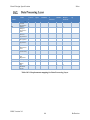
Test Cases ....................................................................................................................... 78
10.
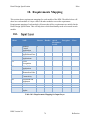
Requirements Mapping ...................................................................................................... 79
10.1.
Input Layer ................................................................................................................. 79
10.2.
Data Processing Layer ................................................................................................ 80
10.3.
Presentation Layer ...................................................................................................... 81
10.4.
Data Storage Layer ..................................................................................................... 82
11.
Acceptance Plan ................................................................................................................. 83
11.1.
Packaging and Installation .......................................................................................... 83
11.2.
Acceptance Testing..................................................................................................... 83
11.1.
Acceptance Criterion. ................................................................................................. 83
12.
Appendix ............................................................................................................................ 85
12.1.
Interface Table Legend ............................................................................................... 85
12.2.
Server .......................................................................................................................... 86
12.3.
Turn on App on Boot up ............................................................................................. 87
DDS Version 2.0
4
Reflection
Detail Design Specification
Echo
Document Revision History
Revision
Number
0.1
Revision Date
12 September 2014
Description
Rationale
First Draft
Initial draft for Echo system
1.0
20 September 2014
Version 1.0
Team Review
2.0
08 October 2014
Version 2.0
Baseline after Feedback and Review
DDS Version 2.0
5
Reflection
Detail Design Specification
Echo
List of Figures
FIGURE
PAGE
Figure 1-1 General System Diagram .............................................................................................. 9
Figure 2-1 : Architecture Design Diagram ................................................................................... 10
Figure 2-2 : Detail Design Diagram.............................................................................................. 15
Figure 2-3: Producer Consumer Diagram (part 1) ........................................................................ 20
Figure 2-4: producer Consumer Diagram (part 2) ........................................................................ 21
Figure 3-1: 23” LCD Screen ......................................................................................................... 22
Figure 3-2: USB extender cable .................................................................................................... 23
Figure 3-3: Android TV Box ........................................................................................................ 24
Figure 3-4: Sound Card Adapter ................................................................................................... 25
Figure 3-5 Microphone ................................................................................................................. 26
Figure 3-6: Speaker System .......................................................................................................... 27
Figure 3-7: Pushbutton Switch...................................................................................................... 28
Figure 3-8: Surge Protector ........................................................................................................... 29
Figure 3-9: HDMI Cable ............................................................................................................... 30
Figure 3-10: AV Cable.................................................................................................................. 31
Figure 5-1: GUI Listener Module ................................................................................................. 33
Figure 5-2: Event Handler Module ............................................................................................... 35
Figure 5-3: Echo Activation Service Module ............................................................................... 37
Figure 5-4: Speech Recognizer Module ....................................................................................... 40
Figure 5-5: System Power Module ............................................................................................... 42
Figure 6-1 Request Processor Module .......................................................................................... 43
Figure 6-2: Command Validator Module ..................................................................................... 46
Figure 6-3: System Boot up Module ............................................................................................. 48
Figure 6-4: Request Handler Module ........................................................................................... 50
Figure 6-5: Command Processor Module ..................................................................................... 54
Figure 6-6: Application Request Processor .................................................................................. 56
Figure 7-1: Dispatcher Module ..................................................................................................... 58
Figure 7-2: Display Formatter ...................................................................................................... 61
Figure 7-3: Speaker Formatter ...................................................................................................... 64
Figure 7-4: Display Formatter ...................................................................................................... 66
Figure 8-1: Data Parser Module .................................................................................................... 68
Figure 8-2: Data Request Formatter ............................................................................................. 70
Figure 8-3: Data Storage Module ................................................................................................. 72
Figure 8-4: Data Retrieval Module ............................................................................................... 74
DDS Version 2.0
6
Reflection
Detail Design Specification
Echo
List of Tables
TABLE
PAGE
Table 3-1: LCD Screen Specifications ......................................................................................... 22
Table 3-2: US extender cable Specifications ................................................................................ 23
Table 3-3: Android TV Box Specifications .................................................................................. 25
Table 3-4: Sound Card Adapter Specifications ............................................................................ 26
Table 3-5: Microphone Specifications .......................................................................................... 27
Table 3-6: Speaker System Specifications .................................................................................... 28
Table 3-7: Pushbutton Switch Specifications ............................................................................... 29
Table 3-8: Surge Protector Specifications .................................................................................... 30
Table 3-9: HDMI Cable Specifications ........................................................................................ 30
Table 3-10: AV Cable Specifications ........................................................................................... 31
Table 5-1: Touch Input Interfaces................................................................................................. 34
Table 5-2 Event Handler Interfaces .............................................................................................. 36
Table 5-3: Echo Activation Interfaces .......................................................................................... 38
Table 5-4: Speech Recognizer Interfaces ..................................................................................... 41
Table 6-1: Request Processor Interfaces ....................................................................................... 44
Table 6-2: Command Validator Interfaces ................................................................................... 47
Table 6-2: Power Input Processor Interfaces ................................................................................ 48
Table 6-3: Request Handler Interfaces ......................................................................................... 51
Table 6-4: Command Processor Interfaces ................................................................................... 54
Table 6-5: Application Request Processor Interfaces ................................................................... 57
Table 7-1: Dispatcher Module Interfaces ..................................................................................... 59
Table 7-2: Display Formatter Interfaces ....................................................................................... 62
Table 7-3: Speaker Formatter Interfaces....................................................................................... 64
Table 7-4: Display Formatter Interfaces ....................................................................................... 66
Table 8-1: Data Parser Interfaces .................................................................................................. 69
Table 8-2: Data Request Formatter Interfaces .............................................................................. 70
Table 8-3: Data Storage Interfaces ............................................................................................... 72
Table 8-4: Data Retrieval Interfaces ............................................................................................. 74
Table 10-1: Requirements Mapping for Input Layer .................................................................... 79
Table 10-2: Requirements mapping for Data Processing Layer ................................................... 80
Table 10-3: Requirements mapping for Presentation Layer ......................................................... 81
Table 10-4: Requirements Mapping for Data Storage Layer........................................................ 82
DDS Version 2.0
7
Reflection
Detail Design Specification
Echo
1. Introduction
This Detailed Design Specification document will provide an in-depth and thorough analysis of
the Echo system. It will expand upon the systems various layers, subsystems, interfaces, and data
flows, all of which were previously introduced in the Architecture Design Specification
document. In addition to this, it will provide breakdown of each subsystem into several unique
modules. All of the specific details necessary to build the system from start to finish will be
included in this document. The document will begin by introducing the product concept,
definition, and system overview. It will then elaborate on the system’s overall architecture and
proceed to outline the details of the various hardware peripherals required for the system’s
construction. Following this, all of the subsystem modules residing within each layer will be
thoroughly explained. The document will conclude by outlining the requirements mapping
approach taken to ensure that all requirements are met accordingly.
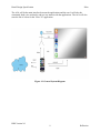
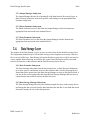
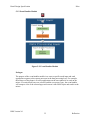
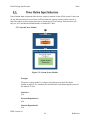
Echo is a Smart Mirror that displays applications from a user’s phone to a mirror. The user will
be able to choose which applications to display on the mirror and enlarge the application to see it
in more detail. It achieves this using an ACA that communicates with and controls the Echo.
Echo will give a better start to the day. The few minutes that you spend in front of the mirror
looking at your reflection could be used more productively. While brushing your teeth you can
inquire about weather, social updates, calendar events, emails, or even listen to music.
Echo is designed for the average consumer who wishes to view information more easily than on
their phone. The ACA will allow the user to select various apps that are on their AndroidTM
phone. The selected apps will be displayed on the mirror and will allow the user to see updated
information, similar to normal locked screen updates.
An example is the busy student. They wake up, go to the bathroom to do their morning rituals,
and they can see what their friends posted on Facebook, figure out how to get that perfect look
for their presentation, play some upbeat music, and see what the weather is like, all while
brushing their teeth and getting ready for the day.
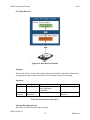
Echo will consist of two major components, the mirror and the ACA. The mirror will hold the
display unit, speakers, microphone, and a motherboard. The display unit will be a LCD screen
that will display user’s requests. The speakers will send sound from the music application or
from the “How-To” application to the user. The microphone will allow the user to interact with
the ACA using voice commands. The motherboard will analyze the voice commands and send it
to the ACA and receive information from the ACA and make it into a display for the screen. The
mirror itself will be a mountable box that will keep all components inside, while keeping
moisture out and allowing sound to come in and heat to dissipate.
DDS Version 2.0
8
Reflection
Detail Design Specification
Echo
The ACA will be the main interface between the applications and the user. It will take the
commands, both voice and touch, and use it to interact with the applications. The ACA will also
store the list of videos for the “How-To” application.
Figure 1-1 General System Diagram
DDS Version 2.0
9
Reflection
Detail Design Specification
Echo
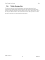
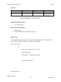
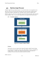
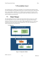
2. Architecture Overview
The following section gives a high level description of our system by breaking it down into
several layers. The system consists of a total of 4 separate layers: Input layer, Data Processing,
Data Storage, and Presentation Layer. A brief description of each layer and their respective sub
layer will be provided in the following sections.
Figure 2-1 : Architecture Design Diagram
DDS Version 2.0
10
Reflection
Detail Design Specification
Echo
The purpose of the Input Layer is to accept input from the user. This will be accomplished in 2
sub-layers: Touch and Hardware.
The Touch Sub-Layer accepts input from the user through the phone’s touch screen. This will
serve as a secondary source of input from the user to the system. Information from the
AndroidTM Control Application (ACA) is sent to this layer where it is initially processed and
then formatted. Once the data has been formatted it is passed to the next layer to be further
processed.
The Hardware Sub-Layer accepts data from the mirror microphone and the power button. This
will serve as the main source of input from the user into the system. This layer will listen for the
key command words spoken by the user. The information will go through an event handler in
order to distinguish what actions need to be taken with the given input (every word after the key
word “Echo” is collected). After the speech recognition has been formatted it is converted to
strings to be sent out for processing.
2.1.1 Touch Input Subsystem
The Touch Input Subsystem provides the user interface to the ACA. It will accept the
input from user through ACA. This subsystem takes in user request of list of applications
to be displayed on Echo and send that list to the Data Processing Layer.
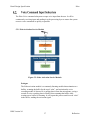
2.1.2 Voice Command Input Subsystem
The Echo Voice command subsystem accepts voice input from the user. It will be
continuously receiving input and sending it to the processing layer to ensure the system
reacts to voice commands as quickly as possible.
2.1.3 Power Input Subsystem
Power Button Input subsystem takes the user request to turn on or turn off the system. It
does not do any data processing in case of power off but when user request to power on
the system, it takes the request to application request processor to launch the ACA on
boot up. Therefore user will only see ACA and not the default launcher of Android TV
Box.
DDS Version 2.0
11
Reflection
Detail Design Specification
Echo
The purpose of the Data Processing Layer is to accept data that has been gathered through the
input layers and to trigger events that correspond with the needs of the user. This layer contains
components to analyze the data that is being received from the other layers. After the data has
been analyzed, it is sent to the app command processor, where the command is processed into a
request and sent to the Internet and database. The appropriate action will be generated and sent to
the presentation layer. This layer also contains a component to deal with API requests to the
Internet as well as their responses.
2.2.1 Touch Input Processor Subsystem
The Touch Input Processor subsystem takes input from the Touch Input subsystem of the
Input layer and formats it to display on the phone ACA. It also sends the selected
applications and associated credentials to the ACA of Echo in form of JSON object over
the server.
2.2.2 Hardware Input Processor Subsystem
Hardware Input Processor subsystem plays a very crucial role in the voice recognition
service that Echo will provide. This subsystem gets input from Speech Recognizer
Module and the System Power module of the Input Layer. The input is sent to respective
modules in the Hardware Input Layer. The Voice Commands are parsed and check
against the valid commands. If the command is valid, it is sent to the Command
Processor module of the Data Processor.
2.2.3 Data Processor Subsystem
Data Processor Subsystem is the brain of the system. This subsystem gets input from the
Hardware Input Processor Subsystem, and the Touch Input Processor Subsystem via the
network. The subsystem then uses the input and executes both the user and the system
functions corresponding to that input. All of the input from the Echo is routed thru this
subsystem in order to be processed, and it then outputs to the Presentation Layer.
The purpose of the Presentation Layer is to present information to the user. This could be via
LCD Screen, the speakers, or the Android™ Control application on the phone. Data to be output
is sent from the Data Processing Layer to the Presentation Layer and is then routed to the correct
output formatter based on the data received. After the data has been formatted to the correct
medium it is presented to the user via that channel.
DDS Version 2.0
12
Reflection
Detail Design Specification
Echo
2.3.1 Output Manager Subsystem
The Output Manager has the job of getting all of the data from the Processing Layer, or
Data Processor Subsystem to be more specific, and sending it to the appropriate Data
Formatter Subsystem.
2.3.2 Phone Formatter Subsystem
The Phone Formatter receives data from the Output Manager which it formats into
appropriate form and sends to the Android Device.
2.3.3 Echo Formatter Subsystem
The Echo Formatter receives data from the Output Manager which it formats into
appropriate form and sends to the Android Device.
The purpose of the Data Storage Layer is to store or retrieve data for the Data Processing Layer.
The components inside this layer will facilitate saving or retrieving data as necessary. Data can
flow in or out of this layer. Data flowing in from the Data Processing Layer will be converted to
a more suitable format for being saved on the file system. Data flowing out will be converted
from its file format to a data structure that the Data Processing Layer can use.
2.4.1 Data Formatter Subsystem
The Data Formatter takes data from the Processing Layer, or Data Processor Subsystem
to be more specific, and formats it from a data structure that is used by the program to a
format that can be passed on to the Data Storage Manager to store on the physical disk. It
can also do the reverse and get the data from the Data Storage Manager and convert it to
a data structure that could be used by the Data Processor.
2.4.2 Data Storage Manager Subsystem
The Data Storage Manager has the job of finding enough free space in the storage device
and storing the data received from the data formatter onto the disk, it also finds the stored
data on the storage device for the data processor
DDS Version 2.0
13
Reflection
Detail Design Specification
Echo
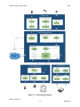
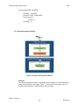
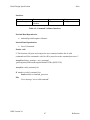
This subsection shows the Detail Design Diagram, which contains subsystems of each
architecture layer and the modules within each subsystem. This section also introduces all the
modules of subsystems with little description of them. In later sections of the document, each of
the subsystems and their modules will be explained in more detail. The figure below also shows
the data flow between each of the subsystems and the modules.
DDS Version 2.0
14
Reflection
Detail Design Specification
Echo
Figure 2-2 : Detail Design Diagram
DDS Version 2.0
15
Reflection
Detail Design Specification
Echo
Input Layer
Touch Input Subsystem
2.5.1 GUI Listener
The GUI listener module takes phone touch screen input from the user by
identifying the type of input, location of input, and then classifies this input for
the data processing layer.
2.5.2 Event Handler
The purpose of the event handler module is to react to specific touch input and
send appropriate requests to the request handler in the data processing layer. For
example, the main use of the phone is to select applications on the users phone to
be used on the mirror. If certain check boxes are selected, and the user presses
sync, the event handler will compose a list of the selected apps and send them to
the mirror.
Voice Command Input
2.5.3 Echo Activation Service
The Echo activation module is a constantly listening module that maintains two
buffers, scanning the buffer for the word “echo”, and activation the voice
recording module if detected. It is pulling data in from the microphone, saving a
second of voice recording data in a buffer, then scanning that buffer while
creating a new buffer for listening. It will repeat this process until it reads “echo”
in the buffer, sending the activation signal.
2.5.4 Speech Recognizer
The speech recognizer module is responsible for recording voice commands after
being activated by the user saying “Echo”. It will record voice input for up to 5
seconds, then send the recorded string out for processing.
Power Input
2.5.5 System Power
The power system module is a simple circuit that powers the Echo Mirror
System on and off. It is a double pole, double throw switch that supplies power to
the android TV box.
DDS Version 2.0
16
Reflection
Detail Design Specification
Echo
Data Processing Layer
Touch Input Processor
2.5.6 Request Processor
The Request Processor obtains list of applications and associated credentials from
the Event Handler of the Touch Input subsystem and converts it into a JSON
Object. The JSON is transferred over the network to the server that is on Android
TV Box.
Hardware Input Processor
2.5.7 Command Validator
This module receives text input from the Speech Recognizer module located in
Input Layer and parses the string into words. After which it filters out the key
commands for example “Open” + “Stocks”, and validates them against the preselected list of commands. It then forwards the commands onto the next module.
2.5.8 Power Input Processor
This module is responsible for opening the Android Control Application on Echo
as the Android TV Box boots up. It receives digital signal input from the System
Power module which turns on the Android TV Box, and from there this module
will be able to launch the ACA.
Data Processor
2.5.9 Request Handler
This module receives the JSON object from the Server via the Network. It will
send a request to the Data Parser for the Echo apps table with the compatible
applications and their paths, which it will then use to create a new Favorites table
with the list of Apps, and their credentials from the JSON objects, and the paths
from the Echo apps table. The new Favorites table will be then sent to the Data
Parser in order to be stored (replaces the older one). The paths from the Favorites
table will be sent to the Dispatcher module in order to be displayed onto the ACA
main screen.
DDS Version 2.0
17
Reflection
Detail Design Specification
Echo
2.5.10 Command Processor
This module receives a string from the Command Validator module. It will use
the android system commands to determine if the command can be processed or
not as per the situation (for example. Open news command will not be processed
if news is already open). If the command can be performed, it will send it to the
Application Request Processor, if not, it will ignore the command. It audits the
commands
2.5.11 Application Request Processor
This module is perhaps the most important module in the system, it performs the
majority of the work. It receives the string command from the Command
Processor module and then performs the actions based on the command. For
example, in order to open an Application, it will first get the path of the
application form the storage manager, specifically from the favorites table, it will
then get the necessary data for the application, either from the Internet or from the
Internal Storage, and then display the content.
Presentation Layer
Output Manager
2.5.12 Dispatcher
The dispatcher module is responsible of receiving data from the application
request processor and the request handler and determines where the output should
go for appropriate output. The dispatcher parsers through the received data and
sends it to the speaker or display formatter accordingly for the output. The
Dispatcher consists of a series of predetermined possible cases for output options.
Phone Formatter
2.5.13 Display Formatter
The display formatter module is responsible of receiving data from the request
processor and creating an appropriate user Interface for the phone. The display
formatter will create new Interface that will show the buttons for the application
that are in the list passed.
DDS Version 2.0
18
Reflection
Detail Design Specification
Echo
Echo Formatter
2.5.14 Speaker Formatter
The speaker formatter module is responsible of receiving data from the dispatcher
and creating an appropriate audio output. The speaker formatter will access the
speech API (API for the voice recognition service).
2.5.15 Display Formatter
The display formatter module is responsible of receiving data from the dispatcher
and creating an appropriate user Interface for the echo. The display formatter will
create new Interface that will show the buttons for the application that are in the
list passed. This module will also open the how-to-app activity page.
Data Storage Layer
Data Formatter
2.5.16 Data Parser
This module will take data in from the Data Processing Layer from the Request
Handler module and the Application Request processor and will deconstruct the
data structure into the different data elements so that the information can be stored
appropriately
2.5.17 Data Request Formatter
This module will take data from the Data Storage module and format all
information into the correct format needed for the different modules that it will
send it out to.
Data Storage Manager
2.5.18 Data Storage
This module will store the information on the hard disk into the proper location
and into the right tables.
2.5.19 Data Retrieval
This module will receive the data requested from the hard disk, combine the
information into appropriate data sections, and send it to the formatter for proper
structuring.
DDS Version 2.0
19
Reflection
Detail Design Specification
Echo
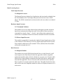
The figure below maps the data flow occurring between the Producer and Consumer modules.
This figure clearly depicts the large amount of data flows coming in and out of some modules
like Request Handler and the Application Request Processor.
Producer
Phone ACA
Microphone
Power Button
Touch Input
GUI Listener
Event Handler
Echo Activation
Service
Speech
Recognizer
System Power
Request
Processor
Power Input
Processor
Command
Validator
Request
Handler
Command
Processor
Application
Request
Processor
Server
Application
Data
HW1
T1
Power Input Processor
Display Formatter
Application Data
Server
Application Request
Processor
Command Processor
Request Handler
Command Validator
Request Processor
System Power
Speech Recognizer
Echo Activation Service
Event Handler
GUI Listener
Touch Input
Echo ACA
Phone ACA
Consumers
HW2
T2
T3
C1
C2
HW4
E1
T4
HW5
C3
C4
D1
E2
D2
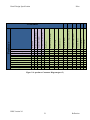
Figure 2-3: Producer Consumer Diagram (part 1)
DDS Version 2.0
20
Reflection
Detail Design Specification
Echo
Echo Monitor
Echo Speakers
Android Phone
Internal Storage (HDD)
Application Request Processor
Request Handler
Data Retrieval
Data Storage
E4
Data Request Formatter
Display Formatter (Echo)
E6
Data Parser
Speaker Formatter
Dispatcher
Display Formatter (phone)
Speaker Formatter
Display Formatter (Echo)
Data Parser
Data Request Formatter
Data Storage
Data Retrieval
Request Handler
Application Request Processor
Internal Storage (HDD)
Display Formatter (Phone)
Dispatcher
Producer
Consumer
T5
E7
E5
DS2
DS6
DS8
DS3
DS5
E3
C5
DS1
DS7
DS4
Figure 2-4: producer Consumer Diagram (part 2)
DDS Version 2.0
21
Reflection
Detail Design Specification
Echo
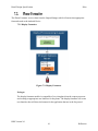
3. System Hardware Description
This section will cover the hardware needed to build an Echo Mirror product. Each component
will detail the quantity needed, purpose of the component, specification and interface for the
item.
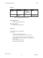
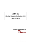
Figure 3-1: 23” LCD Screen
3.1.1 Purpose
The monitor in the mirror will be displaying the applications the user chooses. It
is the main visual user interface with the Echo mirror.
3.1.2 Quantity
The Echo Mirror system only requires one monitor.
3.1.3 Interface
The screen shall interface with the Android TV box.
3.1.4 Specification
23”
1920 x 1080
16:9
HDMI, VGA
LED
Screen Size
Resolution
Aspect Ratio
Video Input Ports
Backlight Technology
Table 3-1: LCD Screen Specifications
DDS Version 2.0
22
Reflection
Detail Design Specification
Echo
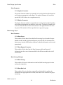
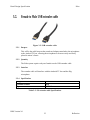
Figure 3-2: USB extender cable
3.2.1
Purpose
This will be the cable between the sound card adapters attached to the microphone
to the Android TV box, allowing the microphone to be more easily and freely
placed in mirror’s frame.
3.2.2
Quantity
The Echo system requires only one female to male USB extender cable.
3.2.3
Interface
The extender cable will interface with the Android TV box and the iRig
microphone.
3.2.4
Specification
Length
Terminal Gender
Type
3 ft
M-F
USB 3.0
Table 3-2: US extender cable Specifications
DDS Version 2.0
23
Reflection
Detail Design Specification
Echo
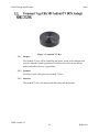
Figure 3-3: Android TV Box
3.3.1
Purpose
The Android TV box will be controlling the mirror, acting as the computer that
runs the Android Control Application. It will drive the screen image and any
audio produced by the user’s applications.
3.3.2
Quantity
The Echo system will require one Android TV box.
3.3.3
Interface
The Android TV box will interact with the screen and the speakers.
DDS Version 2.0
24
Reflection
Detail Design Specification
3.3.4
Echo
Specification
CPU
GPU
RAM
ROM
Wifi
Bluetooth
Buttons
Ports
OS
Power Adapter
Amlogic S802 Quad-Core 2.0G
Mali-450
DDR3 2G
Nand flash 8G
AP6210,Support 802.11 a/b/g/n
Bluetooth v4.0
Update Button (via pinhole), power button
(physical)
USB2.0: 2* Standard USB, 1*Micro USB
with OTG, DC-in: 1*DC in Jack, HDMI:
1* standard A HDMI 1.4b out, 4K*2K,
SPDIF: 1*S/SPDIF out, RJ45: 1*RJ45, TF
Card Slot: 1*TF card slot, AV: 1*AV port
Google Android 4.4, support OTA function
5V 3A
Table 3-3: Android TV Box Specifications
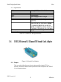
Figure 3-4: Sound Card Adapter
3.4.1
Purpose
This acts as the bridge between the microphone and the Android TV box,
allowing for the most freedom in the placement of the microphone and Android
TV box inside the frame.
DDS Version 2.0
25
Reflection
Detail Design Specification
3.4.2
Echo
Quantity
The Echo Mirror system only requires one sound card adapter.
3.4.3
Interface
The sound card adapter only interfaces with the USB extender and the
microphone.
3.4.4
Specification
Ports
Type
5.1 channel sound, microphone
USB 2.0
Table 3-4: Sound Card Adapter Specifications
Figure 3-5 Microphone
3.5.1
Purpose
This will be the microphone that listens for user voice input. It will be the main
control mechanism of the Echo Mirror system.
3.5.2
Quantity
The Echo Mirror system requires one microphone.
3.5.3
Interface
The microphone will directly interface with the sound card adapter, indirectly
interacting with the Android TV box, supplying voice input from the user.
DDS Version 2.0
26
Reflection
Detail Design Specification
3.5.4
Echo
Specification
Microphone Type
Polar Pattern
Frequency Response
Maximum Sound Pressure
Windscreen
Size
OS Support
Condenser electret
Unidirectional/cardioid
100Hz – 15kHz
110 dB
Built in
30mm/1.18" x 47mm/1.85" x 10mm/0.39"
Android, iOS
Table 3-5: Microphone Specifications
Figure 3-6: Speaker System
3.6.1
Purpose
The speakers will play audio from the phone such as music, video, etc.
3.6.2
Quantity
The Echo Mirror will have 2 speakers.
3.6.3
Interface
The speakers will interface with the Android TV Box
DDS Version 2.0
27
Reflection
Detail Design Specification
3.6.4
Echo
Specification
Type
Size
Voice Coil
Peak Power
Mounting Depth
2-way Speaker
5.25 inches
1” voice coil
100W
1.97”
Table 3-6: Speaker System Specifications
Figure 3-7: Pushbutton Switch
3.7.1
Purpose
This will act as the power button for the system. It will give the Echo Mirror
system the power on and power off signal.
3.7.2
Quantity
The Echo Mirror system requires one DPDT switch.
3.7.3
Interface
The switch will interface with the power switching on the screen and the Android
TV box.
DDS Version 2.0
28
Reflection
Detail Design Specification
3.7.4
Echo
Specification
Contact Form
Current Rating
Switch Function
Voltage Rating AC
Voltage Rating DC
DPDT
6A
ON-OFF
250V
30V
Table 3-7: Pushbutton Switch Specifications
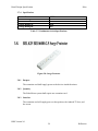
Figure 3-8: Surge Protector
3.8.1
Purpose
The extension cord shall supply power to the devices inside the mirror.
3.8.2
Quantity
The Echo Mirror system shall require one extension cord.
3.8.3
Interface
The extension cord will supply power to the speakers, the Android TV box, and
the screen.
DDS Version 2.0
29
Reflection
Detail Design Specification
3.8.4
Echo
Specification
Length
Outlets
Input Voltage
Output Capacity
2.5 ft
6
125V
1875W
Table 3-8: Surge Protector Specifications
Figure 3-9: HDMI Cable
3.9.1
Purpose
The HDMI cable will connect the Android TV box to the screen, supplying the
video.
3.9.2
Quantity
The Echo Mirror System will require one HDMI cable.
3.9.3
Interface
The HDMI cable will interface with the Android TV box and the screen.
3.9.4
Specification
Length
Terminal Gender
6.5ft
M-M
Table 3-9: HDMI Cable Specifications
DDS Version 2.0
30
Reflection
Detail Design Specification
Echo
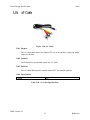
Figure 3-10: AV Cable
3.10.1 Purpose
The AV cable shall connect the Android TV box to the speakers, supplying sound
output for the user.
3.10.2 Quantity
The Echo Mirror system shall require one AV cable.
3.10.3 Interface
The AV cable shall interface with the Android TV box and the speakers.
3.10.4 Specification
Length
3 ft
Table 3-10: AV Cable Specifications
DDS Version 2.0
31
Reflection
Detail Design Specification
Echo
4. System Software Description
This Section describes the software development technologies that will be used to make Echo.
The software parts of Echo are divided into two sections: Android Application and the Android
TV box that will act as the main controller for this Product.
Project will consists of two Android Control Applications (ACA), one for the phone and one for
the mirror. The Applications will be developed to run Android Versions from 4.0 to 4.4. To
implement voice recognition team will be using Android speech libraries.
Echo will use the Android TV Box as its Controller. Echo ACA will be downloaded in Android
TV Box. This app will provide the user interface. Android Box comes with pre- installed
Android OS in it which will make it easy for us to launch other applications like Facebook,
Weather or Twitter from ACA.
DDS Version 2.0
32
Reflection
Detail Design Specification
Echo
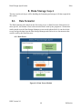
5. Input Layer
The input layer handles all input from the user, includes touch input from the phone and voice
input going into the mirror. It contains the voice recognition API that enables the user to control
the mirror using voice commands, and the graphical user interface on the phone for configuring
the system for the user. Its main functions include the GUI listener, the Echo Activation service,
the Voice Recording Function, and the Power button input subsystem.
The Touch Input Subsystem provides the user interface to the ACA. It will accept the input from
user through ACA. This subsystem takes in user request of list of applications to be displayed on
Echo and send that list to the Data Processing Layer.
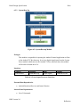
5.1.1 GUI Listener Module
Figure 5-1: GUI Listener Module
DDS Version 2.0
33
Reflection
Detail Design Specification
Echo
Prologue
The GUI listener module takes phone touch screen input from the user by identifying the
type of input, location of input, and then classifies this input for the data processing layer.
Interfaces
Source
Sink
Phone
GUI Listener
GUI Listener
Event Handler
Input Data to
Sink
Touch Input
N/A
Output Data to
Sink
N/A
Sorted Touchscreen
Input, directed
program control to
appropriate touch
screen input section
Table 5-1: Touch Input Interfaces
External Data Dependencies
The module needs user touch screen interaction to process any actions.
Internal Data Dependencies
The actions will be built with Android API levels 20 and up.
Service Dependencies
The action listeners will depend entirely on built in Android touch screen interface
functions.
Pseudo code
//below are examples of touch screen input that will be used by the system, not the action
the //system takes upon touch screen input. The purpose of the GUI listener is to
differentiate //between the different user inputs on the touchscreen.
ON_TOUCH{
Determine location of screen touch
}
ON_SLIDE{
Determine distance slid across screen
}
DDS Version 2.0
34
Reflection
Detail Design Specification
Echo
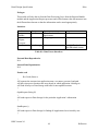
5.1.2 Event Handler Module
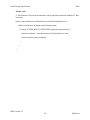
Figure 5-2: Event Handler Module
Prologue
The purpose of the event handler module is to react to specific touch input and send
appropriate requests to the request processor in the data processing layer. For example,
the main use of the phone is to select applications on the users phone to be used on the
mirror. If certain check boxes are selected, and the user presses sync, the event handler
will compose a list of the selected apps and convert it into JSON object and send it to the
mirror.
DDS Version 2.0
35
Reflection
Detail Design Specification
Echo
Interfaces
Producer
GUI Listener
Consumer
Event Handler
Event Handler Request Processor
Input
Location of screen
touch or direction of
slide on screen
(touchscreen API
information)
Selected apps
Output
N/A
List of apps
Table 5-2 Event Handler Interfaces
External Data Dependencies
N/A
Internal Data Dependencies
N/A
Pseudo code
While(1)
If checkbox selected
{
If checkbox already selected
Unselect checkbox
Else
Select checkbox
}
If sync button pressed
Build a list of selected list
Send list to request processor
DDS Version 2.0
36
Reflection
Detail Design Specification
Echo
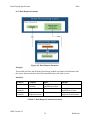
The Echo Voice command subsystem accepts voice input from the user. It will be
continuously receiving input and sending it to the processing layer to ensure the system
reacts to voice commands as quickly as possible.
5.2.1 Echo Activation Service Module
Figure 5-3: Echo Activation Service Module
Prologue
The Echo activation module is a constantly listening module that maintains two
buffers, scanning the buffer for the word “echo”, and activation the voice
recording module if detected. It is pulling data in from the microphone, saving a
second of voice recording data in a buffer, then scanning that buffer while
creating a new buffer for listening. It will repeat this process until it reads “echo”
in the buffer, sending the activation signal.
DDS Version 2.0
37
Reflection
Detail Design Specification
Echo
Interfaces
Producer
Consumer
Microphone Echo Activation
Service
Echo
Voice Recorder
Activation
Module
Service
Input
String Buffer
Output
N/A
“Echo”
identification
Activation Signal
(int)
Table 5-3: Echo Activation Interfaces
External Data Dependencies
The module depends on the voice input from the user.
Internal Data Dependencies
Since the input will be raw voice data, the module will be using a voice
recognition API that simply converts the raw voice data into strings that will fill
the buffers to be used by the module.
Pseudo code
//on system start up//
//global variables for ease of use between threads.
Char[] buffer1, buffer2
Int activate = 0;//initiates activation signal to 0 (off)
int buffer1active = 0;//notifies system buffer1 is taking voice input
int buffer2active = 0;//notifies system buffer2 is taking voice input
Int checking1= 0//notifies system that buffer1 is being checked to stall until buffer
is ready to be deleted
Int checking2=0// notifies system that buffer2 is being checked to stall until buffer
is ready to be deleted
Int EchoListener(string buffer1);//function for identifying echo in string
main(void)
{
buffer1active = 1;
Create thread1, thread2
Run thread1
Run thread2
while(1)
{
DDS Version 2.0
38
Reflection
Detail Design Specification
Echo
If activate = 1
send activate signal to voice recording service
release voice recognition control to voice recorder service
wait 5 seconds for voice recording service
takes back voice recognition control
activate = 0
}
}
Thread1
{
While(1)
{
While(activate);// halts threads while voice recorder is activated
If(buffer2active)do nothing
Else
{
Buffer1active = 1;
Put voice into buffer1//using SpeechRecognitionListener
API in Android
Buffer1active = 0;
Call EchoListener(buffer1, threadID)
While(checking==threadID) do nothing
//waits for checking to be
done before
//continuing
Clear buffer1
}
}
}
Thread2
{
While(1)
{
While(activate);//halts threads while voice recorder is activated
If buffer1active do nothing
Else
{
Buffer2active = 1;
put voice into buffer2//using SpeechRecognitionListener
API in Android
buffer2active = 0;
call echolistener(buffer2, threadID)
while(checking == threadID) do nothing
clear buffer2;
}
}
}
DDS Version 2.0
39
Reflection
Detail Design Specification
Echo
EchoListener(buffer, threadID)
{
Checking = threadID;
Check for “echo” within buffer
If echo detected
Activate =1
Checking = 0;
}
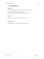
5.2.2 Speech Recognizer Module
Figure 5-4: Speech Recognizer Module
Prologue
The speech recognizer module is responsible for recording voice commands after
being activated by the user saying “Echo”. It will record voice input for up to 5
seconds, then send the recorded string out for processing.
DDS Version 2.0
40
Reflection
Detail Design Specification
Echo
Interfaces
Producer
Echo Activation
Service
Consumer
Voice Recorder
Voice Recorder
Parse Input
Module
Input
Voice Input
passed from the
echo activation
service
N/A
Output
N/A
Recording
command string
Table 5-4: Speech Recognizer Interfaces
External Dependencies
Android Speech Recognizer Library
Internal Dependencies
Android Voice Recognition API
Pseudo code
//continuation of echo activation program
VoiceRecorder
{
While(activation signal not detected);
//waiting for activation signal from echo activation service
Play beep signaling microphone is ready for command input
Accept microphone input using Android Voice Recognition API
Wait 5 seconds
Stop accepting microphone input
Send string to parse input module
}
DDS Version 2.0
41
Reflection
Detail Design Specification
Echo
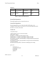
Power Button Input subsystem takes the user request to turn on or turn off the system. It does not
do any data processing in case of power off but when user request to power on the system, it
takes the request to power input processor to launch the ACA on boot up. Therefore user will
only see ACA and not the default launcher of Android TV Box.
5.3.1 System Power Module
Figure 5-5: System Power Module
Prologue
The power system module is a simple circuit that powers the Echo Mirror
System on and off. It is a double pole, double throw switch that supplies power to
the android TV box.
Interfaces
N/A
External Dependencies
N/A
Internal Dependencies
N/A
DDS Version 2.0
42
Reflection
Detail Design Specification
Echo
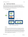
6. Data Processing Layer
This Section introduces the Data Processing Layer and the modules inside its subsystems. Data
Processing Layer receives input from the input layer and performs system functions on the data.
This Layer consists of several subsystems that perform data manipulation and data validation on
the touch input and the hardware input. Each Subsystem will have specific modules to perform
the required action.
The Touch Input Processor subsystem takes input from the Touch Input subsystem of the Input
layer and formats it to display on the phone ACA. It also sends the selected applications and
associated credentials to the ACA of Echo in form of JSON object over the server.
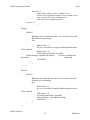
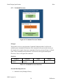
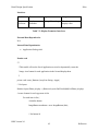
6.1.1 Request Processor
Figure 6-1 Request Processor Module
Prologue
The Request Processor obtains list of applications and associated credentials from the
Event Handler of the Touch Input subsystem and converts it into a JSON Object. The
JSON is transferred over the network to the server that is on Android TV Box.
DDS Version 2.0
43
Reflection
Detail Design Specification
Echo
Interfaces
Producer
Event Handler
Server
Consumer
Request Processor
Request Handler
Input
List of Applications
JSON Object
Output
JSON object
ArrayList with
Package Info
Table 6-1: Request Processor Interfaces
External Data Dependencies
Java Socket library
Internal Data Dependencies
JSON libraries
Various JSON objects containing ArrayLists.
Pseudo-Code
/* This function creates a client- server connection between the ACA of phone and the
ACA of Echo to send the JSON object to the request Handler.*/
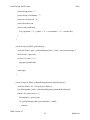
Private class Client{
try {
client = new Socket("10.0.2.2", 4444);
Send JSON object
client.close(); // closing the connection
} catch (IOException e) {
}
}
Private class Server {
DDS Version 2.0
44
Reflection
Detail Design Specification
Echo
try {
serverSocket = new ServerSocket(4444); // Server socket
System.out.println("Server started. Listening to the port 4444");
} catch (IOException e) {
System.out.println("Could not listen on port: 4444");
}
while (true) {
try {
clientSocket = serverSocket.accept();
inputStreamReader = new
InputStreamReader(clientSocket.getInputStream());
bufferedReader = new
BufferedReader(inputStreamReader);
Receive the JSON object
inputStreamReader.close();
clientSocket.close();
} catch (IOException ex) {
System.out.println("Problem in message reading");
}
}
DDS Version 2.0
45
Reflection
Detail Design Specification
Echo
Hardware Input Processor subsystem plays a very crucial role in the voice recognition service
that Echo will provide. This subsystem gets input from Speech Recognizer Module and the
System Power module of the Input Layer. The input is sent to respective modules in the
Hardware Input Layer. The Voice Commands are parsed and check against the valid commands.
If the command is valid, it is sent to the Command Processor module of the Data Processor.
6.2.1
Command Validator
Figure 6-2: Command Validator Module
Prologue
This module receives text input from the Speech Recognizer module located in Input
Layer and parses the string into words. After which it filters out the key commands for
example “Open” + “Stocks”, and validates them against the pre-selected list of
commands. It then forwards the commands onto the next module.
DDS Version 2.0
46
Reflection
Detail Design Specification
Echo
Interfaces
Producer
Speech Recognizer
Consumer
Command
Validator
Input
String
Output
String
Table 6-2: Command Validator Interfaces
External Data Dependencies
Android SpeechRecognizer Libraries
Internal Data Dependencies
List of Commands
Pseudo- code
/* This function will parse and compare the user command with the list of valid
commands and if the command is valid it will be passed on to the command processor */
ArrayList<String> matches = user_command
.getStringArrayListExtra(RecognizerIntent.EXTRA_RESULTS);
ArrayList valid_command_list
If matches in valid_command_list
Send matches to command_processor
Else
Voice message “ not a valid command”
DDS Version 2.0
47
Reflection
Detail Design Specification
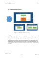
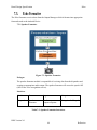
6.2.2
Echo
System Boot Up
Figure 6-3: System Boot up Module
Prologue
This module is responsible for opening the Android Control Application on Echo
as the Android TV Box boots up. It receives digital signal input from the System
Power module which turns on the Android TV Box, and from there this module
will be able to launch the ACA.
Interfaces
Producer
System Power
Consumer
System Boot Up
Input
Digital Signal
Output
Android OS call
Table 6-3: Power Input Processor Interfaces
External Data Dependencies
Android Broadcast Receiver and Intent Libraries
Internal Data Dependencies
List of Commands
DDS Version 2.0
48
Reflection
Detail Design Specification
Echo
Pseudo- code
/* This function will boot up the Android Control Application when the Android TV Box
boots up*/
public class StartMyServiceAtBootReceiver extends BroadcastReceiver {
public void onReceive(Context context, Intent intent) {
if (Intent.ACTION_BOOT_COMPLETED.equals(intent.getAction())) {
Intent serviceIntent = new Intent(context, MySystemService.class);
context.startService(serviceIntent);
}
}
}
DDS Version 2.0
49
Reflection
Detail Design Specification
Echo
Data Processor Subsystem is the brain of the system. This subsystem gets input from the
Hardware Input Processor Subsystem, and the Touch Input Processor Subsystem via the
network. The subsystem then uses the input and executes both the user and the system functions
corresponding to that input. All of the input from the Echo is routed thru this subsystem in order
to be processed, and it then outputs to the Presentation Layer.
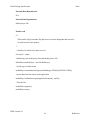
6.2.1
Request Handler
Figure 6-4: Request Handler Module
Prologue
This module receives the JSON object from the Server via the Network. It will send a
request to the Data Parser for the Echo apps table with the compatible applications and
their paths, which it will then use to create a new Favorites table with the list of Apps,
and their credentials from the JSON objects, and the paths from the Echo apps table. The
new Favorites table will be then sent to the Data Parser in order to be stored (replaces the
older one). The paths from the Favorites table will be sent to the Dispatcher module in
order to be displayed onto the ACA main screen.
DDS Version 2.0
50
Reflection
Detail Design Specification
Echo
Interfaces
Producer
Server
Consumer
Request Handler
Input
JSON Object
Data Request
Formatter
Request Handler
Table
Output
List of Apps with
package info
Request
Table 6-4: Request Handler Interfaces
External Data Dependencies
JSON libraries
Various JSON objects containing ArrayLists.
Internal Data Dependencies
Android Applications PackageInfo
Pseudo-code
/* This module gets a JSON Object that contains list of applications that user requested
to open. So a compare function will look at the list of apps in JSON and the list of
installed apps and if that app exists in the Android TV Box, it will copy the package
information of the application, display the icon on the screen and store it in the favorite
list. */
if requested_app in contained_apps
get_package_info
else
show failure message.
/* This helper function retrieves all installed apps with the application name, package
name, version-number and -code as well as the icons. The method getPackages() returns
an ArrayList with all the apps.*/
class PInfo {
private String appname = "";
DDS Version 2.0
51
Reflection
Detail Design Specification
Echo
private String pname = "";
private String versionName = "";
private int versionCode = 0;
private Drawable icon;
private void prettyPrint() {
Log.v(appname + "\t" + pname + "\t" + versionName + "\t" + versionCode);
}
}
private ArrayList<PInfo> getPackages() {
ArrayList<PInfo> apps = getInstalledApps(false); /* false = no system packages */
final int max = apps.size();
for (int i=0; i<max; i++) {
apps.get(i).prettyPrint();
}
return apps;
}
private ArrayList<PInfo> getInstalledApps(boolean getSysPackages) {
ArrayList<PInfo> res = new ArrayList<PInfo>();
List<PackageInfo> packs = getPackageManager().getInstalledPackages(0);
for(int i=0;i<packs.size();i++) {
PackageInfo p = packs.get(i);
if ((!getSysPackages) && (p.versionName == null)) {
continue ;
DDS Version 2.0
52
Reflection
Detail Design Specification
Echo
}
PInfo newInfo = new PInfo();
newInfo.appname = p.applicationInfo.loadLabel(getPackageManager()).toString();
newInfo.pname = p.packageName;
newInfo.versionName = p.versionName;
newInfo.versionCode = p.versionCode;
newInfo.icon = p.applicationInfo.loadIcon(getPackageManager());
res.add(newInfo);
}
return res;
}
DDS Version 2.0
53
Reflection
Detail Design Specification
6.2.2
Echo
Command Processor
Figure 6-5: Command Processor Module
Prologue
This module receives a string from the Command Validator module. It will use the
android system commands to determine if the command can be processed or not as per
the situation (for example. Open news command will not be processed if news is already
open). If the command can be performed, it will send it to the Application Request
Processor, if not, it will ignore the command.
Interfaces
Producer
Command
Validator
Consumer
Command
Processor
Input
String
Output
String
Table 6-5: Command Processor Interfaces
External Data Dependencies
Android Activity Manager Library
DDS Version 2.0
54
Reflection
Detail Design Specification
Echo
Internal Data Dependencies
N/A
Pseudo- Code
/* This function will check if the application is already open before processing the
commands like “next”, “previous”, “ scroll up” or “scroll- down”. If the application id
open the command is processed and command processor request App request Processor
to pull data from internet, else user will hear a “command cannot be processed” message.
To check is an app is already open will be use the code given below*/
public string isForeground(String PackageName){
// Get the Activity Manager
ActivityManager manager = (ActivityManager)
getSystemService(ACTIVITY_SERVICE);
// Get a list of running tasks, we are only interested in the last one,
// the top most so we give a 1 as parameter so we only get the topmost.
List< ActivityManager.RunningTaskInfo > task = manager.getRunningTasks(1);
ComponentName componentInfo = task.get(0).topActivity;
// Check if it matches our package name.
If (componentInfo.getPackageName().equals(PackageName))
send command to Application Request Processor
// If not then requested application is not open
Voice message “ Command Cannot be Processed”
}
DDS Version 2.0
55
Reflection
Detail Design Specification
6.2.3
Echo
Application Request Processor
Figure 6-6: Application Request Processor
Prologue
This module is perhaps the most important module in the system, it performs the majority
of the work. It receives the string command from the Command Processor module and
then performs the actions based on the command. For example, in order to open an
Application, it will first get the path or package information of the application from the
storage manager, specifically from the favorites table, it will then get the necessary data
for the application, either from the Internet or from the Internal Storage, and then display
the content.
DDS Version 2.0
56
Reflection
Detail Design Specification
Echo
Interfaces
Producer
Command
Processor
System Power
Internet
Data Request
Formatter
Consumer
Application
Request Processor
Application
Request Processor
Application
Request Processor
Application
Request Processor
Input
Digital Signal
Output
Application
Interfaces
Android OS Call
Request
Application Data
Request
Path to
Applications
String
Table 6-6: Application Request Processor Interfaces
External Data Dependencies
Android application services that provide the Application Request Processor
Module with the application data.
Internal Data Dependencies
Applications PackageInfo to get the path
Pseudo – code
/* This function is a code snippet of how to open an app from ACA, For example if user
says command “open Facebook”, following code will be used to process the request */
public static Intent getOpenFacebookIntent(Context context) {
try {
context.getPackageManager().getPackageInfo("com.facebook.katana", 0);
return new Intent(Intent.ACTION_VIEW, Uri.parse("fb://profile/<id_here>"));
} catch (Exception e) {
return new Intent(Intent.ACTION_VIEW,
Uri.parse("https://www.facebook.com/<user_name_here>"));
}
}
DDS Version 2.0
57
Reflection
Detail Design Specification
Echo
7. Presentation Layer
Our presentation layer’s modules serve the purpose of receiving data from the data processing
layer and formatting it into presentable form for the user interfaces and the audio. It has three sub
layers, output manager, which takes care of sending requests to appropriate formatters, phone
formatter that takes care of the output to the phone, and the Echo formatter which takes care of
audio and display on the Echo mirror
The Output Manager has the job of getting all of the data from the Processing Layer, or Data
Processor Subsystem to be more specific, and sending it to the appropriate Data Formatter
Subsystem. Since most of the data is provided by Android Application Services, we don’t have
to format most of the data coming to the presentation layer. We will be formatting how we
display the application icons on the mirror.
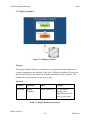
7.1.1 Dispatcher
Figure 7-1: Dispatcher Module
DDS Version 2.0
58
Reflection
Detail Design Specification
Echo
Prologue
The dispatcher module is responsible of receiving data from the application request
processor and the request handler and determines where the output should go for
appropriate output. The dispatcher parsers through the received data and sends it to the
speaker or display formatter accordingly for the output. The Dispatcher consists of a
series of predetermined possible cases for output options.
Interfaces
Producer
Consumer
Input
Output
App
request
processor
Dispatcher
Struct: speaker or
display data
String: Audio file path
and Display data
Request
Handler
Dispatcher
Struct: Selected apps String: Display data
Table 7-1: Dispatcher Module Interfaces
External Data Dependencies
N/A
Internal Data Dependencies
Application package information
DDS Version 2.0
59
Reflection
Detail Design Specification
Echo
Pseudo-code
/**
*This model will use the destination specified in the struct to send the data to the
*appropriate formatter model.
*/
Public void dispatcher (Struct S){
If (S.destination == Speaker_Formatter) {
//send S.data to the speaker formatter
}
Else if (S.destination == Echo_Formatter){
//send S.data to the Echo formatter
}
Else {
//call exception for invalid destination
}
DDS Version 2.0
60
Reflection
Detail Design Specification
Echo
The Phone Formatter receives data from the Output Manager which it formats into appropriate
form and sends to the Android Device
7.2.1 Display Formatter
Figure 7-2: Display Formatter
Prologue
The display formatter module is responsible of receiving data from the request processor
and creating an appropriate user Interface for the phone. The display formatter will create
new Interface that will show the buttons for the application that are in the list passed.
DDS Version 2.0
61
Reflection
Detail Design Specification
Echo
Interfaces
Producer
Consumer
Input
Output
Request
Processor
Display
Formatter
String: Selected apps Visual response:
display icons.
Table 7-2: Display Formatter Interfaces
External Data Dependencies
N/A
Internal Data Dependencies
Application Package info
Pseudo-code
/**
* This model will use the list of application received to dynamically create the
* image view button for each application in the list and display them.
*/
private void create_Buttons (ArrayList<String> Apps){
// Get layout
RelativeLayout Phone_display = (RelativeLayout) findViewById(R.id.Phone_display)
//create a button for each app name in list
For each item in list {
//initialize button
ImageButton newbutton =new ImageButton (this);
// Set button id
DDS Version 2.0
62
Reflection
Detail Design Specification
Echo
newbutton.setId (item number)
// Add app image
newbutton.setSrc (item name.getSrc ())
// Add button text
newbutton.setText (item name)
// New layout params for each button
RelativeLayout.LayoutParams lp = new
RelativeLayout.LayoutParams (RelativeLayout.LayoutParams.WRAP_CONTENT,
RelativeLayout.LayoutParams.WRAP_CONTENT)
//specify button location
Ip.addRule (RelativeLayout.RIGHT_OF, item number-1)
//Add button to view
Phone_display.addView (newbutton, lp);
}
DDS Version 2.0
63
Reflection
Detail Design Specification
Echo
The Echo Formatter receives data from the Output Manager which it formats into appropriate
form and sends to the Android Device
7.3.1 Speaker Formatter
Figure 7-3: Speaker Formatter
Prologue
The speaker formatter module is responsible of receiving data from the dispatcher and
creating an appropriate audio output. The speaker formatter will access the speech API
(API for the voice recognition service).
Interfaces
Producer
Consumer
Input
Output
Dispatcher
Speaker
Formatter
Audio response:
outputs response
String: Audio file path
Table 7-3: Speaker Formatter Interfaces
DDS Version 2.0
64
Reflection
Detail Design Specification
Echo
External Data Dependencies
N/A
Internal Data Dependencies
Media player API.
Pseudo-code
/**
*This model will get an audio file path receive from the dispatcher and convert it
*to audio send it to the speaker.
*/
// initialize Uri which is the data received.
Uri myUri = s.data;
//initializing your media player from the Media player API
MediaPlayer mediaPlayer = new MediaPlayer();
//set the type of audio stream
mediaPlayer.setAudioStreamType(AudioManager.STEAM_NOTIFICATION);
//get the data from the source in the application
mediaPlayer.setDataSource(getApplicationContext(), myUri);
// Play the file.
mediaPlayer.prepare();
mediaPlayer.start();
DDS Version 2.0
65
Reflection
Detail Design Specification
Echo
7.3.2 Display Formatter
Figure 7-4: Display Formatter
Prologue
The display formatter module is responsible of receiving data from the dispatcher and
creating an appropriate user Interface for the echo. The display formatter will create new
Interface that will show the buttons for the application that are in the list passed. This
module will also open the how-to-app activity page.
Interfaces
Producer
Consumer
Input
Output
Dispatcher
Display
Formatter
String: display data
Visual response:
display icons,
Application interface,
how-to-app activity
Table 7-4: Display Formatter Interfaces
DDS Version 2.0
66
Reflection
Detail Design Specification
Echo
External Data Dependencies
N/A
Internal Data Dependencies
N/A
Pseudo-code
/*** This model will use the list of application received to dynamically create the image
view button for each application in the list and display them. */
private void create_Buttons (ArrayList<String> Apps){ // Get layout
RelativeLayout Phone_display = (RelativeLayout) findViewById(R.id.Phone_display)
//create a button for each app name in list
For each item in list {
//initialize view
ImageView newIcon =new ImageView (this);
// Set button id
newIcon.setId (item number)
// Add app image
newIcon.setSrc (item name.getSrc ())
// New layout params for each button
RelativeLayout.LayoutParams lp = new
RelativeLayout.LayoutParams (RelativeLayout.LayoutParams.WRAP_CONTENT,
RelativeLayout.LayoutParams.WRAP_CONTENT)
//specify view location
Ip.addRule (RelativeLayout.RIGHT_OF, item number-1)
//Add image to layout
Phone_display.addView (newbutton, lp);
}
DDS Version 2.0
67
Reflection
Detail Design Specification
Echo
8. Data Storage Layer
This layer and its sub layers will be handling the formatting and storage of all data required for
this system.
The Data Formatter takes data from the Processing Layer, or Data Processor Subsystem to be
more specific, and formats it from a data structure that is used by the program to a format that
can be passed on to the Data Storage Manager to store on the physical disk. It can also do the
reverse and get the data from the Data Storage Manager and convert it to a data structure that
could be used by the Data Processor.
8.1.1 Data Parser
Figure 8-1: Data Parser Module
DDS Version 2.0
68
Reflection
Detail Design Specification
Echo
Prologue
This module will take data in from the Data Processing Layer from the Request Handler
module and the Application Request processor and will deconstruct the data structure into
the different data elements so that the information can be stored appropriately
Interfaces
Producer
Request
Handler
Application
Request
Processor
Data Parser
Consumer
Data Parser
Output
N/A
Data Parser
Input
Struct: Credentials for
Applications
String: Application name
Data Storage
N/A
String[]: The data for
each individual section
N/A
Table 8-1: Data Parser Interfaces
External Data Dependencies
N/A
Internal Data Dependencies
N/A
Pseudo-code
RcvCreds (Struct c)
{
will separate the structure into application name, user name, password, and path
will place into preset locations into array based on which application it belongs to
will send all arrays to Data Storage with nulls for non updated sections
}
OpenRequest (String N)
{
will send request to Data Storage for the particular Application’s information
}
StartRequest ()
{
will send request to Data Storage for finding all Applications last selected by user
}
DDS Version 2.0
69
Reflection
Detail Design Specification
Echo
8.1.2 Data Request Formatter
Figure 8-2: Data Request Formatter
Prologue
This module will take data from the Data Storage module and format all information into
the correct format needed for the different modules that it will send it out to.
Interfaces
Producer
Consumer
Data Retrieval Data Request
Formatter
Data Request Request Handler
Formatter
Data Request Application
Formatter
Request Processor
Input
String[]: List of
applications to show
N/A
N/A
Output
N/A
String[]: List of
applications to show
Struct: Requested
Application information
Table 8-2: Data Request Formatter Interfaces
DDS Version 2.0
70
Reflection
Detail Design Specification
Echo
External Data Dependencies
N/A
Internal Data Dependencies
N/A
Pseudo-code
StartUp(String[] s)
{
Receives the list of applications that will be displayed on start up
Sends just the list of applications needed for display
}
OpenCreds(String AppName, String UN, String PW, String Path)
{
receives all application information and places it into a struct, then sends to the
Application Request Processor
}
DDS Version 2.0
71
Reflection
Detail Design Specification
Echo
The Data Storage Manager has the job of finding enough free space in the storage device and storing
the data received from the data formatter onto the disk, it also finds the stored data on the storage
device for the data processor
8.2.1 Data Storage
Figure 8-3: Data Storage Module
Prologue
This module will store the information on the hard disk into the proper location and into
the right tables.
Interfaces
Producer
Data Parser
Consumer
Data Storage
Data Storage
Hard Disk
Input
String[]: The data for each
individual section
N/A
Output
N/A
String: Data for each
application
Table 8-3: Data Storage Interfaces
External Data Dependencies
N/A
DDS Version 2.0
72
Reflection
Detail Design Specification
Echo
Internal Data Dependencies
Android SQLite Database
Pseudo-code
StoreCreds(String[] AppName, String[] UN, String[] PW, String[] Path)
{
Stores all information into the appropriate table
The AppName String will be used to determine the startup list
}
StartRqst()
{
Search database for all applications needed for startup
}
OpenRqst(String N)
{
Search database for all credentials for particular application
}
DDS Version 2.0
73
Reflection
Detail Design Specification
Echo
8.2.2 Data Retrieval
Figure 8-4: Data Retrieval Module
Prologue
This module will receive the data requested from the hard disk, combine the information
into appropriate data sections, and send it to the formatter for proper structuring.
Interfaces
Producer
Hard Disk
Consumer
Data Retrieval
Data
Retrieval
Data Request
Formatter
Input
String: applications for
start, application
credentials
Data Request
Output
Data Request
Application Icons and
Interfaces
Table 8-4: Data Retrieval Interfaces
External Data Dependencies
Hard Disk Operational and has data requested
DDS Version 2.0
74
Reflection
Detail Design Specification
Echo
Internal Data Dependencies
N/A
Pseudo-code
OpenCreds(String AppName, String UN, String PW, String Path)
{
Will receive the data from the hard disk and place all needed information into a String[]
for Data
Request Formatter
}
StartApps(String AppName)
{
Will receive the list of Applications that need to b displayed at startup and send it as a
String[]
}
DDS Version 2.0
75
Reflection
Detail Design Specification
Echo
9. Quality Assurance
The following section will contain a brief description of how each of the module and the system
as a whole will be tested. The System Test Plan document will contain in greater detail the test
for each of the modules, subsystems, and the system as a whole.
We will be simultaneously testing the hardware and the software for the system. Every
individual hardware part will be tested out of the box for DOA (Dead on Arrival), after which we
will test them for functionality. More details will be provided in the System Test Plan.
We will be using the White Box Testing approach at the Unit testing level. Rather than testing
the Functionality of the entire subsystem, we will be testing the functionality at each of the
modules. Below we have a brief description on how each of the modules will be tested.
9.2.1.
9.2.2.
Input Layer
9.2.1.1.
GUI Listener: This module will be able to listen for any events that
happen in the Android Control Application on the Android device.
9.2.1.2.
Event Handler: This module will be able to handle the events that happen
in the Android Control Application on the Android device.
9.2.1.3.
Echo Activation Service: This module will continuously listen for the
“Echo” command keyword to be spoken.
9.2.1.4.
Speech Recognizer: This module will turn on speech recognition once the
command word has been spoken.
9.2.1.5.
System Power: This module will listen for Power button to be pressed on
the Echo.
Data Processing Layer
9.2.2.1.
Request Processor: This module will send a JSON object over the
network.
9.2.2.2.
Command Validation: This module will parse and validate the string
from voice recognition.
9.2.2.3.
Request Handler: This module will be able to create a favorite apps list
from JSON object and a list of default apps.
9.2.2.4.
Command Processor: This module will be able to validate commands.
9.2.2.5.
Application Request Processor: This module will be able to start
applications and retrieve the necessary data for the applications.
DDS Version 2.0
76
Reflection
Detail Design Specification
9.2.3.
9.2.4.
Echo
9.2.2.6.
Server: This module will receive a JSON object and transfer it forward to
Request Handler module.
Data Storage Layer
9.2.3.1.
Data Parser: This module will deconstruct data structures into different
data elements and prepare it for storage.
9.2.3.2.
Data Request Formatter: This module will reconstruct data elements
into desired data structures and send it to appropriate module.
9.2.3.3.
Data Storage: This module will store the data onto the internal storage.
9.2.3.4.
Data Retrieval: This module will retrieve the data from the internal
storage.
Presentation Layer
9.2.4.1.
Dispatcher: This module will be direct the data that needs to be presented
to appropriate peripherals.
9.2.4.2.
Speaker Formatter: This module will format the data received into audio
format and direct it to speakers.
9.2.4.3.
Display Formatter (Echo): This module will format the data receive into
user interface and direct it to the monitor.
9.2.4.4.
Display Formatter (Phone): This module will format the data receive
into user interface and direct it to the phone screen.
9.2.4.5.
We will be using the White Box Testing approach at the Component testing level. The
functionality for each of the layers will be tested. Below we have a brief description on how each
of the layers will be tested.
9.3.1.
Input Layer: The Android control application on the phone will be able to take in
input by touch from the user and the android control application on the Echo will be able to
take in input from the user by voice commands.
9.3.2.
Data Processing Layer: The system will be able to parse data, validate
commands, execute the commands, and retrieve the necessary data from other layers.
9.3.3.
Data Storage Layer: The system will be able to retrieve the requested data and
store data as well.
9.3.4.
Presentation Layer: The system will be able to format the data received from the
Data processing layer and be able to present it onto the peripherals.
DDS Version 2.0
77
Reflection
Detail Design Specification
Echo
We will be using the Black Box testing approach at the system verification testing level. The
functionality of the entire application will be tested using the requirements and the acceptance
criterion specified by the development team and the sponsors.
Below are a few test cases that we will be using to determine if the system as a whole is working
as we intended it to work.
The User can select favorite applications using their phone.
o Expected Results: The user chooses their favorite applications from the
pre-selected list and synchronizes the phone with the Echo to select
favorite applications.
The User can open an application.
o Expected Results: The user speaks the correct voice command in order to
open an application and Echo will recognize and open that application.
The User can interact with an application.
o Expected Results: The user speaks the correct voice command in order to
interact with an application and Echo will recognize and perform that
action on the application.
The User can view a How-To Video.
o Expected Results: The user speaks the correct voice command to open
and view a video on the how-to application and the Echo recognizes that
command and plays the video on the monitor.
The User can turn on or turn off the system.
o Expected Results: The user presses the power button on Echo and the
system shuts down or turns on depending on the current state.
DDS Version 2.0
78
Reflection
Detail Design Specification
Echo
10. Requirements Mapping
This section shows requirements mappings for each module of the DDS. The tables below will
show how each module of a layer works with other modules to meet the requirement.
Requirements mapping of each module will ensure that all key requirements are satisfied in the
Detail Design Specification. This will help show which functionality needs to be tested in each
module.
Requirement
Number
Requirement
Name
GUI
Listener
3.1
AndroidTM
Control
Application
Display Multiple
Application Icons
Switch between
Applications
Voice
Recognition
“How-To”
Application
Speakers
Mounted on Echo
Server
Connectivity
Resolution and
Brightness
Microphone
Power Button
Pill Reminder
Applet
3.2
3.3
3.4
3.5
3.6
3.7
3.8
3.9
3.10
3.11
Event
Handler
Continuous
speech
Recognition
Service
Voice
Recognizer
System
Power
Table 10-1: Requirements Mapping for Input Layer
DDS Version 2.0
79
Reflection
Detail Design Specification
Requiremen
t
Number
Requiremen
t Name
Request
Processo
r
3.1
AndroidTM
Control
Application
Display
Multiple
Application
Icons
Switch
between
Applications
Voice
Recognition
“How-To”
Application
3.2
3.3
3.4
3.5
3.6
3.7
3.8
3.9
3.10
3.11
Echo
Parse
Input
Command
Validation
Request
Handler
App
Request
Processor
System Boot
up
Speakers
Mounted on
Echo
Server
Connectivity
Resolution
and
Brightness
Microphone
Power
Button
Pill
Reminder
Applet
Comman
d
Processor
Table 10-2: Requirements mapping for Data Processing Layer
DDS Version 2.0
80
Reflection
Detail Design Specification
Echo
Requirement
Number
Requirement Name
Dispatcher
Phone
Formatter
Speaker
Formatter
3.1
AndroidTM Control
Application
3.2
Display Multiple Application
Icons
3.3
Switch between Applications
3.4
Voice Recognition
3.5
“How-To” Application
3.6
Speakers Mounted on Echo
3.7
Server Connectivity
3.8
Resolution and Brightness
3.9
Microphone
3.10
Power Button
3.11
Pill Reminder Applet
Echo
Formatter
Table 10-3: Requirements mapping for Presentation Layer
DDS Version 2.0
81
Reflection
Detail Design Specification
Echo
Requirement
Number
Requirement Name
Data
Parser
Data Request
Formatter
Data Retrieval
Data Storage
3.1
AndroidTM Control
Application
3.2
Display Multiple Application
Icons
3.3
Switch between Applications
3.4
Voice Recognition
3.5
“How-To” Application
3.6
Speakers Mounted on Echo
3.7
Server Connectivity
3.8
Resolution and Brightness
3.9
Microphone
3.10
Power Button
3.11
Pill Reminder Applet
Table 10-4: Requirements Mapping for Data Storage Layer
DDS Version 2.0
82
Reflection
Detail Design Specification
Echo
11. Acceptance Plan
The following section will discuss the acceptance criterion that needs to be met in order for the
product to be complete. The acceptance plan outlines the Acceptance Criterion, Acceptance
Testing, and the Packaging and Installation information for the Echo.
11.1.
Packaging and Installation
Echo will be pre-assembled and will come in a wooden housing no bigger than 44” x 24” x 8”. It
will come with a Power Cord to power the system, a User’s Manual, a Troubleshooting Guide,
and an USB stick containing the accompanying Android Application.
In order to install the Android Application, the user must insert USB stick into a computer and
connect the android phone to the same computer, after which the user must simply transfer the
APK file onto the phone and run it to install it.
11.2.
Acceptance Testing.
Echo will be tested to ensure that all of the High and Critical priority requirements stated in the
System Requirement Specification are met. The project will be complete after the requirements
are tested and completed. The details about the acceptance testing will be included in the System
Test Plan document.
Echo must meet the following requirements in order to be considered complete by the team
Reflection and the sponsor.
11.1.1. Android Control Application (ACA): Echo must have an Android application
accompanying it that will be able to control it.
11.1.2. Display Multiple Applications Icons: Echo and the ACA must be able to display
multiple application icons.
11.1.3. Switch between Applications: The user must be able to switch between applications
using Voice commands.
11.1.4. Voice Recognition: The user can use voice commands to interact with Echo.
11.1.5. How-To Application: Echo must have a How To application on it.
11.1.6. Speakers: Echo shall have speakers mounted on to it.
11.1.7. Resolution and Brightness: Echo will have a high enough resolution and be bright
enough so that the user will be able to see all information displayed clearly.
11.1.8. Microphone: Echo will have a microphone built onto it.
DDS Version 2.0
83
Reflection
Detail Design Specification
Echo
11.1.9. Power Button: Echo will have an external power button to allow the user to conserve
energy and to power down the system if desired.
11.1.10.
Mirror Housing: The components of Echo will be attached to the inside of the
wooden housing to secure them in place
11.1.11.
Mirror Size: Echo will be no larger than 44” x 24” x 8”.
11.1.12.
Smart Phone Control Latency: There will exist a small delay of up to a second
between the input controls and the corresponding action of the mirror due to processing delay.
11.1.13.
Speaker Quality: Echo speakers must have high quality so that the user can clearly
hear the system.
11.1.14.
Microphone Quality: The microphone mounted on Echo must be of high quality such
that the voice commands are correctly interpreted by the system.
11.1.15.
Installation: The system shall include adequate anchors and screws such that it
can be safely secured to the wall.
11.1.16.
Packaging Safety: The system shall be packaged such that there will be no
exposed circuitry to the user.
11.1.17.
Heat Dissipation: The system shall be able to dissipate the heat generated by the
components of the system
11.1.18.
User Manual: The system shall come with a User’s Manual.
11.1.19.
Troubleshooting Guide: The system shall come with a Troubleshooting guide.
11.1.20.
Moisture Control: Echo will prevent moisture from damaging components
within the system.
DDS Version 2.0
84
Reflection
Detail Design Specification
Echo
12. Appendix
The following section will contain any formulas and algorithms not covered in the software
requirement section.
This section will give a brief overview of how the Interface tables under each module’s sections
are to be read
Producer: This is the module that sends the input to the consumer.
Consumer: This is the receiving module that receives input from the producer.
Input: This is the data that is passed on from the producer to consumer.
Output: This is the data that is passed on from Consumer onto some module or
peripheral.
DDS Version 2.0
85
Reflection
Detail Design Specification
Echo
This section will describe the relevant information about the server module. It will describe the
location, the functionality, and other characteristics of the server module needed to fully
understand it.
Figure 12-1: Server Module on Echo
The server that is included in the DDS will be run on the Echo, inside the Android TV Box as a
part of the ACA on Echo. It will be a Bi-directional communication between client (Android
Phone) and the Server (Echo), using socket programming. The server will load up when the
Android TV Box boots up, and it will reserve its own IP and port. The client (Phone) will then be
able connect to the server using this IP address and port and directly send JSON object
containing the List of applications and their credentials. All of the communication happens on
local Wi-Fi network and no connection to the internet is necessary for the server communication.
DDS Version 2.0
86
Reflection
Detail Design Specification
Echo
The code snippet below is what will make sure that the Android Control Application that is on
Android TV Box (ECHO) will open up at the system boot up time.
// Courtesy of Sean Schulte
// http://stackoverflow.com/questions/6391902/how-to-start-an-application-on-startup
// First, you need the permission in your AndroidManifest.xml
<uses-permission android:name="android.permission.RECEIVE_BOOT_COMPLETED" />
// Also, in your AndroidManifest.xml, define your service and listen for the
BOOT_COMPLETED action:
<service android:name=".MyService" android:label="My Service">
<intent-filter>
<action android:name="com.myapp.MyService" />
</intent-filter>
</service>
<receiver
android:name=".receiver.StartMyServiceAtBootReceiver"
android:enabled="true"
android:exported="true"
android:label="StartMyServiceAtBootReceiver">
<intent-filter>
<action android:name="android.intent.action.BOOT_COMPLETED" />
</intent-filter>
</receiver>
// Then you need to define the receiver that will get the BOOT_COMPLETED action and
start your service.
public class StartMyServiceAtBootReceiver extends BroadcastReceiver {
@Override
public void onReceive(Context context, Intent intent) {
if (Intent.ACTION_BOOT_COMPLETED.equals(intent.getAction())) {
Intent serviceIntent = new Intent(context, MySystemService.class);
context.startService(serviceIntent);
}
}
}
DDS Version 2.0
87
Reflection