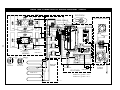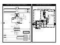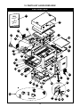
1
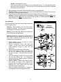
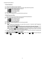
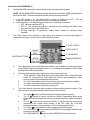
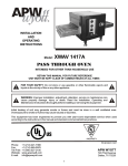
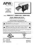
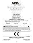
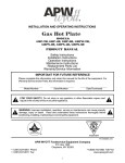
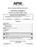
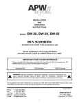
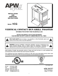
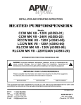
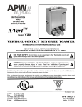
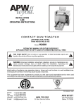
R INSTALLATION AND OPERATING INSTRUCTIONS XWAV 1422 XWAV 1829EZ Models: XWAV-1422, -1829, -1422EZ & -1829EZ PASS THROUGH OVEN INTENDED FOR OTHER THAN HOUSEHOLD USE RETAIN THIS MANUAL FOR FUTURE REFERENCE UNIT MUST BE KEPT CLEAR OF COMBUSTIBLES AT ALL TIMES ! FOR YOUR SAFETY: Do not store or use gasoline or other flammable vapors and liquids in the vicinity of this or any other appliance. ! ! WARNING: Improper installation, adjustment, alteration, service or maintenance can cause property damage, injury or death. Read the Installation, Operating and Maintenance Instructions thoroughly before installing or servicing this equipment. ! Initial heating of unit may generate smoke or fumes and must be done in a well ventilated area. Overexposure to smoke or fumes may cause nausea or dizziness. This equipment has been engineered to provide you with year-round dependable service when used according to the instructions in this manual and standard commercial kitchen practices. ANSI/NSF4 Phone: Fax: Toll Free: Website: E-mail: P/N 96000079 9/06 +1 (214) 421-7366 +1 (214) 565-0976 +1 (800) 527-2100 www.apwwyott.com [email protected] APW WYOTT 729 Third Avenue Dallas, TX 75226 1 IMPORTANT FOR FUTURE REFERENCE Please complete this information and retain this manual for the life of the equipment. For Warranty Service and/or Parts, this information is required. Model Number Serial Number Date Purchased TABLE OF CONTENTS SECTION ITEM 1 2 3 4 5 6 ! ! PAGE Owner's Information Safety Information Specifications Installation Instructions Operation Cleaning 2 2 3 4 6 14 SECTION ITEM 7 8 9 10 11 Troubleshooting Preventative Maintenance Wiring Diagrams Parts List & Exploded View Warranty WARNING: In Europe, appliance must be connected by an earthing cable to all other units PAGE 14 15 15 24 27 in the complete installation and thence to an independent earth connection in compliance with EN 60335-1 and/or local codes ! WARNING: An earthing cable must connect the appliance to all other units in the complete installation and from there to an independent earth connection. ! 1. OWNER’S INFORMATION General Information: 1. 2. 3. Always clean equipment thoroughly before first use. (See general cleaning instructions). Check rating label for your model designation and electrical rating. For best results, use stainless steel counter tops. General Operation Instructions: 1. 2. 3. All food-service equipment should be operated by trained personnel. Do not allow your customers to come in contact with any surface labeled “CAUTION HOT”. Never touch ceramic or steel heaters. Warranty Information: Reliability Backed By APW Wyott’s Warranty: All APW Wyott Pass Through Ovens are backed by a one year parts and labor warranty, including On-Site Service calls within 50 miles of authorized service technicians. Service Information: Service Hotline (800) 733-2203 2. SAFETY INFORMATION APW Wyott equipment is designed, built and sold for commercial use and should be operated by trained personnel only. Clearly post all CAUTIONS, WARNINGS and OPERATING INSTRUCTIONS near each unit to insure proper operation and to reduce the chance of personal injury and/or equipment damage. This product is used for the cooking, defrosting or re-thermalization of food products only. Always disconnect power before servicing the unit. Surfaces will remain hot after power has been turned off. Allow unit to cool before cleaning or servicing. Never clean the unit by immersing it in water. The unit is not protected against water jets; DO NOT CLEAN PASS THROUGH OVEN WITH A WATER JET. Always clean equipment properly before first use. 2 3. SPECIFICATIONS OVERALL DIMENSIONS - XWAV-1422, -1829, -1422EZ & -1829EZ A B C J DE Dimensions: K F H I G L INCHES (mm) DIMENSION A B C D E F G H I J K L XWAV1422 24.5 21.0 15.1 18.0 14.0 16.8 10.5 22.0 43.0 3.8 18.0 4.00 (622) (533) (385) (457) (356) (425) (267) (559) (1092) (97) (457) (102) XWAV 1829 28.0 25.0 19.1 18.0 14.0 24.1 10.5 29.5 50.5 3.8 22.0 4.0 (711) (635) (486) (457) (356) (611) (267) (749) (1283) (97) (559) (102) XWAV1422EZ 24.5 21.0 15.1 18.0 14.0 16.8 10.5 22.0 43.0 3.8 18.0 4.0 (622) (533) (385) (457) (356) (425) (267) (559) (1092) (97) (457) (102) XWAV1829EZ 28.0 25.0 19.1 18.0 14.0 24.1 10.5 29.5 50.5 3.8 22.0 4.0 (711) (635) (486) (457) (356) (611) (267) (749) (1283) (97) (559) (102) Electrical Rating: MODEL XWAV1422 XWAV1829 XWAV 1422EZ XWAV 1829EZ WATTS 5400 5400 7200 7200 5500 5500 7000 7000 VOLTS AMPS (1 Phase) 26.0 22.5 34.6 30.0 26.4 22.9 33.7 29.2 208 240 208 240 208 240 208 240 3 NEMA PLUG 6-30P 6-30P 6-50P 6-50P 6-30P 6-30P 6-50P 6-50P Power Cord: Six (6) foot, 3 wire grounded cord. If the supply cord is damaged, the manufacturer, or an authorized service agent, must replace it in order to avoid a hazard and warranty. Please contact the factory by calling the 800 # located on the unit. Shipping Weights: XWAV1422 115 lbs. (52.2 kg.) XWAV 1829 149 lbs. (67.6 kg.) XWAV1422EZ XWAV1829EZ 115 lbs. (52.2 kg.) 149 lbs. (67.6 kg.) 4. INSTALLATION INSTRUCTIONS If the carton appears damaged, or damage is discovered once the carton is opened, stop immediately and contact the freight company to file a damage claim. ! CAUTION: The Pass Through Oven is shipped assembled. The unit is shipped with urethane supports between the top heaters and the conveyor assembly. Please remove all urethane supports and packaging materials before operating the unit. Failure to remove all packaging materials may lead to a fire and / or damage to the appliance. ! 1. Remove all external packaging that is protecting top portion of unit. 2. Remove unit from shipping container while in the upright position. The unit can be lifted out of the carton by grasping under the conveyor on each side of the appliance. Please remove the plastic bag. 3. Remove all internal packaging to the unit. Important: Remove urethane supports located inside the tunnel oven between the top heaters and the conveyor. Remove tape from conveyor trays. Remove tape from extrusion corners. Remove tape from deflecting curtains located just above entrance and exit of conveyor. 4. Visually inspect all external and internal portions of unit for damage. Important: Inspect the top white ceramic elements located inside the oven tunnel after removal of urethane supports. To inspect these white ceramic elements, use a small mirror held under each element to detect cracks. Important: The Ceramic elements are fragile and will break under stress. Do not twist, pull, push, or otherwise subject the white ceramic elements to stress. 5. Wipe down the exterior of the unit using a damp cloth with warm water. Do not use abrasive pads or cleaners as they will damage the stainless steel surface and high temperature plastic. NOTE: DO NOT USE CLEANERS OF ANY KIND ON THE WHITE CERAMIC HEATERS. 6. Remove four feet from box and install into threaded nuts located at the four corners underside of the left and right housings; Also remove conveyor extension tray(s). Conveyor extensions should be hung off end of conveyor frame. Model XWAV 1422EZ and XWAV 1829EZ will have two conveyor extensions for loading and exit ends. 7. Place unit in operating location. Note: Ambient Conditions - Make sure that the operating location is in an area where the ambient temperature is held constant (minimum 70°F). Please avoid areas such as near exhaust fans and air conditioning ducts. Warning: Operating environment Ensure that operation location is at a reasonable distance from combustible walls and materials otherwise combustion or discoloration could occur. Stand-off/Air-divider located on rear panel is important in maintaining proper division of inlet and exhaust air flow - If removed it could result in improper functioning of unit and MAY cause personal injury and WILL void your warranty. 4 Caution: Operating environment Place unit on a stable, level counter at a convenient height for use. Turn the adjustable feet so that unit is level to counter top. The top of the unit is not intended for use a shelf. Materials placed there are at risk for fire. 8. Before plugging unit into wall, make sure that the switch is in the off position. 9. Warning: Ensure no hands, tools or parts or other unintended items are located on the conveyor as injury will result when unit is turned on. 10. Plug unit into grounded electrical outlet with correct voltage, and plug configuration. Warning: Using any receptacle that is not designed to match the attached cord and plug MAY cause personal injury and WILL void your warranty. Please attach the XWAV1422/Medium Size unit, 208V, 5400W only, to an individual branch circuit. Oven Stacking FIGURE 1 The stacking kit will consist of 4 corner posts to be inserted between stacked units. Remove End Caps & Screws Before Installing Kit Warning: When stacking, unit must have proper stacking kit installed. This will prevent overheating and damaging of electrical components. Warning: Do not stack more than three units tall or do not use more than two stacking kits. Warning: Standoff on rear panel of unit is important to allow proper inlet and exhaust fan airflow. Do not cover inlet or exhaust fan openings as this could damage electrical components. 1. Ensure bottom unit is mounted on secure surface, with feet installed. 2. Remove respective corner end caps and screws. This will allow each of the stacking spacer retaining fingers to slide into the extrusions. 3. Remove the feet from the top unit as shown. 4. Secure each stacking spacer to the bottom of the unit as shown by using the bolts and washers provided. You should have four total of each. 5. Once the stacking kit spacers are secure, place top unit onto bottom unit. The stacking kit spacers each have tapered guides to allow the unit to lock into position. 6. Refer to Figure 1. Install rear support bracket and screws as shown. Each stacking kit requires that two brackets be mounted on the backside only. One bracket near the strain relief and one at the opposite end. 7. Refer to Cleaning Instructions for cleaning of stacking spacers and cleaning between units. 5 Stacking Kit #94000189 5. OPERATION 1. The controls that operate the belt conveyor and the heaters are located on the front of the unit. 2. A. (NON-EZ MODELS) 1. The On/Off switch is used to turn the unit on or off. Once the unit is turned on the conveyor will automatically run. Warning: Ensure no hands, tools or parts are located on the conveyor as injury will result when unit is turned on. 2. The control display (oval keypad) is used to control top and bottom heat only. The control settings allow for separate upper and lower zone control. The settings for upper and lower zones are 1 through 15; 1 being coolest and 15 being hottest setting. (See control operation below) B. (EZ MODELS) 1. The direction of the belt conveyor travel is controlled by a hidden rocker switch located beneath the left side conveyor extension, behind a removable cover attached to the base housing panel. To change belt direction, remove this cover, flip the rocker switch to the opposite setting, and replace the cover. This operation can be performed while the belt is moving. 3. Note: Before moving the On / Off switch to the “On” position, please read the following statements: 4. A. CAUTION: HOT SURFACES! The exterior metal surfaces of the unit will get hot enough to cause burns. Avoid touching these surfaces to prevent injury. B. WARNING: SEVERE BURN HAZARD CERAMIC HEATERS (top heaters). The white ceramic heaters located in the top of the unit operate at very high temperatures. DO NOT TOUCH HEATERS AFTER UNIT IS TURNED ON. 5. Two adjustable deflector shields are located at the inlet/outlet of the unit, above the conveyor belt. These shields are designed to keep maximum heat inside the unit. Position the shields as needed for product flow. CAUTION HOT SURFACE! Control Operation (NON-EZ MODELS): 6. This oven has 3 heating zones, 2 on top, and a bottom one. The 2 top zones share the same parameters (set point, probe offsets, etc.) The bottom zone is completely independent of the top one. 6 USER INTERFACE Top Zone Selected Active Top Zone Active Bottom Zone Up Bottom Zone Selected Alarm Down Bottom Zone Top Zone There are 4 keys: Bottom Zone, Top Zone, Up, and Down. There are also 5 status LEDs: 2 that indicate the currently selected Zone; and 2 that indicate the zone Heater output state; and 1 for the Alarm conditions. 7. Operating Modes A. Display Set point temperature is displayed as a range: 1, 2, 3,..., 14, 15. 1 corresponds to the lowest sensor temperature and 15 corresponds to the highest sensor temperature. The factory default setting is 8. Once the settings are changed and the unit is turned off, these new settings will remain in memory and appear in the display once the unit is turned on. B. Preheat Mode · · · · · · Unit powers up in this state Unit displays Lo and the active bottom and active top LEDs are on whenever the corresponding zone output is active. A normal press of Bottom Zone key selects this zone (its LED lights up) and display shows its current set point for 5 seconds A normal press of Top Zone key selects this zone (its LED lights up) and display shows its current set point for 5 seconds Up and Down keys are used to change set point of current zone. Set point is displayed for 5 seconds after last Up or Down key press, then normal display resumes. Default set points are defined in Lowlevel parameters. Preheat state ends when both top and bottom zones are within the Low Temperature threshold defined in Low-level programming. C. Ready Mode · · · Unit displays rdy and the active bottom and active top LEDs are on whenever the corresponding zone output is active. All keys work in the same fashion as for the Preheat mode Ready state ends when one of the top or bottom zones fall below the Low Temperature threshold defined in Low-level programming (unit then goes back to Preheat mode) 7 8. Special Features/Alarms A. Zone Probe Error · · · · · Heater probe is disconnected or defective Normal user interface operation applies, but heater output remains inoperative Display flashes Alarm LED as well as an Alarm ID: o AL1 for Zone 1 (Bottom probe) o AL2 for Zone 2 (Top, probe A) o AL3 for Zone 3 (Top, probe B) Alarm shuts down all outputs Probe must be replaced or re-connected to allow normal use B. High Temperature Error · · · · · · · · Heater element is too hot, most likely due to external SSR that failed short Display flashes Alarm LED as well as an Alarm ID: o AL4 for Zone 1 (Bottom probe) o AL5 for Zone 2 (Top, probe A) o AL6 for Zone 3 (Top, probe B) Alarm shuts down heater regulation. The alarm threshold temperature is Low-level programmable Algorithm: o In normal use, if temperature ever goes above (set point + threshold), High Temperature Error is immediately triggered. o If set point is changed (lowered) by the user, the unit will look at the current temperature for 2 minutes and display HI. The peak temperature reached during this time is recorded. o Thereafter, unit monitors the temperature until it reaches set point. During this cooldown time, standard HI message is still displayed. User may change set point again, but 2-minute timer is not restarted (and old Peak value still applies.) During the cooldown time, if ever the temperature rises above the previously recorded peak temperature, High Temperature Error is triggered. Once set point is reached, rdy is displayed again. HI is displayed only if other zone is rdy or also HI. If other zone is Lo, then LH (low-high) is displayed instead of HI. 8 Control Operation (EZ MODELS): 6. The Main ON/OFF rocker switch controls electric power to the electronic controller. NOTE: If the ALARM BUZZER should sound when the switch is turned ON, PRESS the I/0 button to MUTE the ALARM. The alarm condition still exists, but the buzzer is turned OFF. a. In the OFF position ( 0 ), the digital display is blank, all functions are OFF. The rear exhaust/cooling fans may run because they are controlled by thermostats. b. In the ON position ( I ), the digital display will show the current state of operation: 1. OFF belt and heaters are OFF, or 2. REC “X” unit operating according to user-defined recipe settings: belt speed (cooktime), and heat values (top & bottom); or 3. Scrolling message of importance, stating action needed to continue proper operation. 7. The Control Panel of the controller is shown below, and consists of a large 5-digit display, 6 rectangular status lights, and 6 control buttons with indicator lights 5 - DIGIT DISPLAY CONTROL BUTTONS ON/OFF STATUS LIGHTS HEAT UP (INCREASE) RECIPE DOWN (DECREASE) COOK TIME a. The 5-digit display shows both letters and numbers, and is capable of scrolling messages. In the Recipe Programming Mode (Section 6.3), a flashing arrow appears on the left side pointing to the value being modified. b. The status lights indicate what is happening to various areas of the unit: 1. Three “Heat Zone” lights show when heat is being added, Zone 1 being the bottom, Zones 2 & 3 being the top. These lights also come on when pressing the “Heat” button to see the current temperature of the zones. 2. The “Time” status light comes on when the cook-time is being viewed or modified. 3. The “Alarm” light indicates when an alarm condition exists. 4. The “Belt” light indicates if the belt is moving or not. c. The Control buttons are used to make changes to various settings needed for recipes. They also are used to view present settings of the current recipe being run. 1. 2. 3. 4. 5. 6. The “Heat” button controls the heat values for top and bottom heaters. The “R” R (Recipe) is used to access the Recipe Programming Mode where individual recipe parameters are entered, including belt speed, top heat, and bottom heat. The “I/0” I/O button turns the controller ON/OFF. In the ON mode, the unit operates according to the current recipe desired. In the OFF mode, the “Low-Level Programming Mode” may be accessed. This is for Advanced Users Only. The “Clock” button indicates cook time, and controls the belt speed. The “UP ARROW” button is used to INCREASE various settings, whether recipe selections, belt speed, or heat. The “DOWN ARROW” button is used to DECREASE the same settings. 9 8. Control Operating Modes There are 4 Modes of operation with this appliance: 1. 2. 3. 4. OFF HEAT (normal Mode) RECIPE PROGRAMMING ALARM Because each Mode is capable of several functions, careful study should be given to their details to maximize appliance utility. The LOW-LEVEL Programming Mode should only be accessed by an authorized, advanced user or Service Professional. 1. Off Mode (display Reads Off) This Mode allows three (3) functions: a. LOCKing / UNLOCKing of the control buttons (keypad). When the keypad is LOCKED, the temperature set points, cook-time, and recipe changes are no longer accessible to the user. All other functions operate normally, including recipe selection. 1. To change the current state to the other, PRESS the UP button for 5 seconds. The current state will be displayed. 2. PRESS the UP button immediately a second time for 5 or more seconds. This will change the state to the opposite value. 3. If the second PRESS is not done properly, the original state will remain. b. LANGUAGE Selection 1. PRESS the HEAT button for 5 seconds to view the present Language setting: ENGLISH or ESPANOL. 2. Use the UP or DOWN arrow to select the desired language. 3. DO NOT press anything for 5 seconds and the new selection is retained. 4. The following messages are available in both languages: a. OFF (APAGADO) b. LOCKED (BLOQUEADO) c. UNLOCKED (DESBLOQUEADO) d. ZONE OVERHEAT CALL FOR SERVICE (SOBRECALENTAMIENTO ZONA LLAMADA DE SERVICIO) e. PROBE FAILURE CALL FOR SERVICE (FALLA SENSOR LLAMADA DE SERVICIO) 2. Heat Mode (normal Mode of Operation) IF the display reads OFF, PRESS the I/0 button to Enter this Mode. PRESS the I/0 button again to Exit this Mode. This Mode allows seven (7) functions: a. Recipe Selection. Use the UP/DOWN buttons to toggle to the next recipe. The display will show the current recipe selection as “REC 1”, “REC 2”, etc. (NOTE: This is the Default display setting.) b. Heat Regulation. As the recipe requirements dictate, the controller supplies power to the various heat zones. When there is a Call For Heat in any Heat Zone, the status light of the respective Zone will be illuminated. NOTE: Top heaters are regulated independently of the Bottom heater. c. Temperature Setting Viewing. PRESS and HOLD the HEAT button repeatedly to see the current temperature of Zones 1,2,3 in succession. (Zone 1 = Bottom, Zone 2 = Top Left, Zone 3 = Top Right). 10 d. Temperature Setting “Tweaking”. This feature allows “1-time” adjustments to temperature settings that will be lost when a new recipe is selected. 1. PRESS and HOLD HEAT button for 10 seconds. A flashing arrow appears on the left side of the display, pointing to the value that is now available for “tweaking”. 2. Use the UP & DOWN ARROWs to adjust the values to new settings. 3. Successive PRESSes of the HEAT button jumps to the next Temperature Zone, where these settings may now be “tweaked”. NOTE: “Tweaked” temperature settings remain good as long as the recipe is unchanged. When a new recipe is selected, “tweaked” settings are lost. e. Cook-time Regulation. As the recipe requirements dictate, the controller monitors and adjusts the belt speed to achieve the desired cook-time. NOTE: COOK-TIME is defined as: “The time required for the product Leading Edge to Enter and Exit the Cook Zone”. COOK-TIME DOES NOT MEAN leading Edge IN to Trailing Edge OUT. There is an important difference and should be understood by the operator. f. Cook-time Viewing. PRESS and HOLD the Clock button to see the current cook-time setting (belt speed). NOTE: 0.30 = 30 seconds; 3:45 = 3 minutes, 45 seconds, etc. NOTE: Factory default minimum and maximum cook-times are set at 30 seconds (1422), 38 seconds (1829) and 10:00 minutes (both 1422 and 1829). g. Cook-time “Tweaking”. This feature allows “1-time” adjustments to cook-time settings that will be lost when a new recipe is selected. 1. PRESS and HOLD CLOCK button for 10 seconds. A flashing arrow appears on the left side of the display, pointing at the value that is now available for “tweaking”. 2. Use the UP & DOWN ARROWs to adjust the values to a new setting. NOTE: “Tweaked” cook-time settings remain good as long as the recipe is unchanged. When a new recipe is selected, “tweaked' settings are lost. 3. Recipe Programming Mode This Mode allows the user to set the temperature and cook-time values for every recipe that is desired. There are a maximum of 20 recipes that can be programmed by the user. Recipe NAMES are not programmable. All values entered into recipes remain saved in memory and ARE NOT LOST when the unit is turned OFF. The controller starts at Recipe 1 every time the unit is turned ON. This cannot be modified. This Mode allows three (3) functions: a. Bottom Heat (Zone 1) temperature setting. 1. PRESS and HOLD the R (Recipe) button for 5 seconds. A flashing arrow appears on the left side of the display, pointing at the value that is now ready for programming. 2. Use the UP & DOWN ARROWs to adjust the values to the new temperature setting. For accelerated scrolling, HOLD the ARROW button down. 3. DO NOTHING for 5 seconds and the new value is saved in memory. 11 b. Top Heat Zones [2 (left side, top) & 3 (right side, top)] temperature setting. Duplicate steps for Bottom Heat setting. NOTE: Zones 2 & 3 are tied together (internal software coding) and CANNOT be set at different values. c. Cook-time setting. 1. PRESS and HOLD CLOCK button for 5 seconds, until a flashing arrow appears on the left side of the display, pointing at the value that is now ready for programming. 2. Use the UP & DOWN ARROWs to adjust the value to the new cook-time setting. 3. DO NOTHING for 5 seconds and the new value is saved in memory. NOTE: If the UP & DOWN ARROWs are not PRESSed within 15 seconds of when the flashing arrow appears, the controller jumps out of Recipe Programming Mode and retains the previous recipe values. NOTE: These same steps must be repeated for each recipe. After each recipe is programmed, the display returns to display REC “X”. Use the UP & DOWN arrow to jump to the next recipe and repeat the process as described above. 4. Alarm Mode This Mode alerts the operator to situations that the controller has detected as faulty operation that needs attention. An ALARM BUZZER starts beeping loudly when such a situation is detected. PRESS the I/0 button to MUTE the BUZZER. The alarm condition still exists, the ALARM status light continues to flash, but the buzzer is cancelled. Alarm conditions are in two (2) categories: (a) Temperature Probe Failure; (b) Overheat Conditions. a. Temperature Probe Failure. Whenever any of the three temperature probes fail (2-top, 1-bottom), the controller alerts the operator (loud buzzer beeping). Only when the alarm condition has been fixed will the buzzer not sound when the unit is turned ON via the I/0 button. A qualified service professional should replace the faulty probe for proper operation to resume. The controller automatically responds to such conditions, depending on which type of failure has occurred. Responses are as follows: 1. Scrolling message on the display: PROBE FAILURE CALL FOR SERVICE. 2. The affected zone status light flashes. 3. If either of the Top probes has failed, the controller continues to regulate top heat as if nothing had happened. This is because each probe is a redundant item for the other. With one probe input invalid, the controller reads the other input as valid. 4. If both Top probes should fail, the controller reverts to a preset “duty cycle” program that allows a reduced amount of top heat to be generated. Since there is no reliable top probe input, the controller controls power to the heaters on an “ON/OFF” percentage basis, such as 66% time ON, 33% time OFF. This is done to prevent a possible “Overheat” condition, since there is now no reliable means to sense an Top overheat condition. 5. If the Bottom probe should fail, the controller reverts to a preset “duty cycle” program similar to the dual-Top probe failure mentioned above. 12 NOTE: In Ineither either case case where the unit is in in aa“duty “dutycycle” cycle”mode, mode,the theoperator operatorcan canstill stilluse usethe until isservice is performed correct theHowever, failure. However, the reduced heat the unit untilunit service performed to correcttothe failure. the reduced valuevalue will affect the output capacity of theof unit. heat will affect the output capacity the unit. NOTE: A normal operator response may be as such: 1. 2. 3. 4. 5. PRESS the I/0 button to MUTE the buzzer. The scrolling PROBE FAILURE message goes away. The ALARM status light stays illuminated. All other functions continue as normal: a. Display shows current recipe selection. Recipe selection is still possible. b. Belt moves and belt status light is illuminated. c. Heat Zone status lights will be dark. If the HEAT button is pressed to view current temperatures, the unaffected zones will display their current temperature, but the affected zone(s) will scroll the PROBE FAILURE message, without any beeping buzzer. b. Overheat Conditions. NOTE: If unexpected smoke should appear around the unit during an Overheat Alarm condition, turn the Main Switch OFF. Overheat conditions result from excessive power being applied to the heaters. Such situations usually arise from a solid-state relay that has failed CLOSED, of which there is one for each heat zone (three total). However, over-voltage conditions can also cause excess heat, even though the relays are OK. Therefore, it is necessary to properly trouble-shoot such conditions to correctly identify the problem. A qualified technician should make any needed repairs. The maximum allowable temperature is programmable in the LOW-LEVEL PROGRAMMING Mode, and is factory set at 1100°F (593°C). The controller automatically responds to such conditions as follows: 1. 2. 3. Scrolling message on the display: TEMPERATURE ZONE OVERHEAT - CALL FOR SERVICE. Alarm status light is illuminated. By shutting OFF ALL power to ALL heaters until Overheat condition resolved. NOTE: A normal operator response may be as such: 1. 2. 3. 4. PRESS the I/0 button to MUTE the buzzer. The scrolling OVERHEAT message goes away. The ALARM status light stays illuminated. All other functions continue as normal: a. Display shows current recipe. Recipe selection is still possible. b. Belt moves and belt status light is illuminated. c. Heat Zone status lights will be dark. 5. If the HEAT button is pressed to view current temperatures, the unaffected zones will display their current temperatures, but the affected zone(s) will scroll the OVERHEAT message, without any beeping buzzer. (Since there is no power going to the heaters, the temperatures should be lower than normal, UNLESS a failed relay is continuing to power the heater(s). 13 6. CLEANING Insure the appliance has been turned off and has had sufficient time for all surfaces to cool down before cleaning. Use only mild soap and water to clean this appliance. Appliance cleaning should be performed daily. NOTE: DO NOT USE ABRASIVE PADS OR CLEANING SOLUTIONS ON THIS APPLIANCE. Daily Cleaning ! ! Remove the crumb pans and wipe out debris with a damp rag and mild soap solution. Remove the deflector panels located at the entrance and exit of the oven tunnel. Wipe down the area under the deflector panels, and the deflector panels, with a damp rag and mild soap. Reinstall the deflector panels by reversing the procedure used to remove them. ! ! ! Using a damp rag with mild soap and water, wipe down the exterior surfaces of the appliance. Using a damp rag with mild soap solution, wipe down all areas of the conveyor. DO NOT ATTEMPT TO CLEAN THE UPPER WHITE CERAMIC, OR LOWER METAL HEATERS. When units are in the stacked configuration, it is still necessary to clean between the units. Using a damp rag with mild soap and water, wipe down the tops and undersides of all units. Ensure there are no foreign objects between the units that could catch fire. ! Using a damp rag with mild soap and water, wipe the surfaces of the stacking spacers on all four corners. 7. TROUBLESHOOTING Always ask and check the following: Not getting power: 1. 2. 3. 4. 5. Is the unit connected to a live power source of the proper voltage? Check the rating label. Is the unit connected to the correct power source? Check the circuit breaker. Is power switch “ON” and led displaying information? If the above checks out, and you still have problems, call your local service agent. Conveyor not working (NON-EZ MODELS): 1. Please refer to “Not getting power” section. 2. Is the knob turnedto correct setting per desired speed? 3. Note: At slower settings the conveyor moves very slow and may appear stalled, which is not the case. 4. If the above checks out and you still have problems, call your local service agent. Conveyor not working (EZ MODELS): 1. Please refer to “Not getting power” section. 2. Check belt for obstructions. Belt may be jammed. 3. Reverse belt direction to check for belt jam - locate Reversing Switch on left side, beneath conveyor frame, hidden by removable cover. Remove cover, flip switch, and note if belt begins to move backwards. Does belt move backwards? 4. If YES, then clear belt jam and reset belt direction via Reversing Switch. 5. If NO, then call your local service agent. 6. Note: At slower settings the conveyor moves very slow and may appear stalled, which is not the case. 7. If the above checks out, and you still have problems, call your local service agent. 14 Food not cooking properly: 1. 2. 3. 4. Please refer to “Not getting power” section. Are the controller and speed control adjusted to the desired setting? Are the deflector curtains in the proper position? If the above checks out, and you still have problems, call your local service agent. 8. PREVENTATIVE MAINTENANCE SCHEDULE ! ! ! ! ! ! ! Please follow the cleaning section for the daily preventative maintenance schedule. DO NOT USE ABRASIVES OR CLEANING SOLUTIONS ON THIS APPLIANCE. Routinely check before every operation that adequate distance is allowed between fans and anything that would possibly allow foreign debris or substances to be taken in by inlet fan. Clean fan guards on a daily basis to ensure proper inlet cooling to electrical components and efficient hot air exhaust. On a daily basis make sure side walls of tunnel oven remain clean to assist in maintaining even cooking around product. Be careful not to bump or hit the upper ceramic heaters when wiping down. Ensure belt is properly tensioned as to prevent slippage or binding, which causes strain on motor. DO NOT ATTEMPT TO MAINTENANCE, SERVICE OR CLEAN THE UPPER CERAMIC AND LOWER METAL HEATERS. 9. WIRING DIAGRAMS/SCHEMATICS OVERHEAD XWAV1829 (NON-EZ MODELS) OVERHEAD XWAV1422 (NON-EZ MODELS) RTD 2 To: Controller AN2 To: Relay To: Terminal Block To: Terminal Block RTD 3 To: Controller AN3 RTD 3 To: Controller AN3 RTD 3 11 11 10 12 12 9 REAR HEATERS ZONE 3 RTD 3 10 9 RTD 2 11 11 10 12 12 9 REAR HEATERS ZONE 3 RTD 2 13 13 15 14 14 16 10 13 14 16 13 RTD 2 15 14 16 RTD 2 FRONT HEATERS ZONE 2 To: Relay To: Terminal Block FRONT HEATERS ZONE 2 16 To: Relay To: Terminal Block To: Relay 15 RTD 2 To: Controller AN2 15 16 15 9 LEFT SIDE HOUSING (NON-EZ MODELS) UNDER CARRIAGE (NON-EZ MODELS) Motor wiring for left to right configuration of conveyor belt non-reversable switch BLACK (-) ORANGE(+) RED (+) T.STAT 1 TO: POWER SWITCH GREEN (-) L2 1 2 L2 26 5 L1 L1 94100134 5/24V DC OUTPUT L1 L2 2 T.STAT GR 26 208 V 2 POWER CORD L1= BLACK L2= WHITE 5 TO: POWER SWITCH 16 RED BLACK 1. ORANGE 1. OPEN OR FEMALE TERMINAL GR BL 2. WHITE 3. BLUE 4. RED 5. OPEN 6. BLACK 4. RED A1 24 24 T1/2 1/L1 7 7 T2/4 3/L2 T3/6 OR GR BLUE 94000172 TO 3 POLE TERMINAL BLOCK A2 2. WHITE 3. BLUE MOTOR SPEED POT TO SPEED TO SPEED TO SPEED MOTOR-ORANGE MOTOR-GREEN MOTOR-BLUE 5. GREEN 6. BLACK MOTOR CONTACTOR MALE TERMINAL TO 3 POLE TERMINAL BLOCK 94200093 RIGHT SIDE HOUSING (NON-EZ MODELS) 29 TO CONTACTOR "A1 " TO POWER SUPPLY 6 PIN-RED 28 5 TO 2 POLE TERMINAL BLOCK 2 TO 2 POLE TERMINAL BLOCK 5/L3 14 13/NO 22 21/NC 28 RED BL GR OR 29 TO: POWER SWITCH MOTOR SPEED POT. 29 30 POWER SWITCH ESCUTCHEON XWAV LADDER SCHEMATIC (NON-EZ MODELS) L1 L2 TOP FAN EXHAUST TEMPERATURE SWITCHES BOTTOM FAN COOLING POWER SUPPLY 85 - 265 VAC INPUT, 1~ 24 VDC / 5 VDC OUTPUT TO REVERSE DIRECTION OF CONVEYOR BELT, CONNECT / DISCONNECT WHITE WIRE TO TERMINAL “A2” ON CONTACTOR. - + CONTACTOR COIL C1 A1 MAIN SWITCH A2 WHITE C1 BRUSHLESS MOTOR M1 BLUE C1 ORANGE C1 GREEN CONVEYOR SPEED POT ZONE 1 ZONE 2 ZONE 3 RTD BTM RTD TOP RTD TOP INPUTS ECM-3 DIGITAL TEMP CONTROL +++ OUTPUTS SSR1 R1 R2 R3 --SOLIDSTATE RELAYS (1) BOTTOM ELEMENT SSR2 SSR3 TOP ELEMENTS Note: 1417 = (5) Top Elements 1422 = (6) Top Elements 1829 = (8) Top Elements 17 XWAV 1422EZ POWER SUPPLY WIRING DIAGRAM 208 or 240VAC, 1 PH, 50/60 HZ 3 26 ZONE 1 SSR - DC + 8 16 8 ZONE 2 SSR - DC + 19 9 MAIN ON / OFF SWITCH 9 ZONE 3 SSR - DC + 20 21 USER INTERFACE KEYPAD TIME ZONE1 RTD PROBE 3 ZONE 1 - BOTTOM HEAT 29 29 26 23 ZONE 2 ZONE3 HEAT ON / OFF BELT ALARM 22 RECIPE COOKTIME 23 23 CABLE RTD PROBE 18 13 12 15 10 11 16 9 9 16 3 BELT REVERSE SWITCH 1 2 3 10 15 208240 VAC IN BLACK L1 6 RED BLACK -24VDC BLK RED +24VDC RED -24VDC WHITE 26 30 6 7 6 WH 208 or 240VAC, 1 PH, 50/60 Hz Power Supply, 5500 Watts 27 FAN THERMOSTAT MOTOR SIGNAL PROCESSOR RED BLK YEL 24 7 5 WH WH YEL BLU RED BLK 2 BLK CONVEYOR MOTOR 24VBLDC 1 2 28 18 REAR FANS L2-WHITE 23 A1+ 17 2 25 5 SELECT VOLTAGE JUMPER 17 5 L1-BLACK G P16 YEL RED 5 5 6-30P 18 5L3 3L2 1L1 A2- P20 + RED YEL 7 13 N.O. COIL 24 L2 25 COM N.O. WH 10 L1 24 PRODUCT FLOW 15 3 26 NOTE: Top & Bottom Heaters are either 208V or 240V, and must match power supply voltage. 25 CONTACTOR 17 P16 YEL L2/N 4 14 + 19 20 + 14 6T3 4T2 2T1 N.O. CONTACTOR 24VDC COIL P20 + RED + 21 _ 22 + 120 208 240 --- +++ BLK - AN2 AN3 7 RED AN1 30 24 VDC OUT TOP HEAT ZONE 3 24 29 29 ECM-3 CONTROLLER D RT E OB PR 4 AC RELAY TOP HEAT ZONE 2 28 28 MOTOR POWER SUPPLY 4 FAN THERMOSTAT 2 XWAV 1422EZ LADDER WIRING SCHEMATIC L1 L2 TOP FAN EXHAUST THERMOSTATS BOTTOM FAN COOLING POWER SUPPLY 85 - 265 VAC, 1~ INPUT 24 VDC OUTPUT - + MAIN SWITCH BELT REVERSING SWITCH CONTACTOR COIL C1 17 C1 YEL WH R M1 BLU P20 + RED 18 A2 - BLK BRUSHLESS MOTOR 2 C1 BLK 24 7 MSP P16 - YEL ZONE 2 RTD TOP +5VDC ZONE 1 RTD BTM ZONE 3 RTD TOP ANALOG INPUTS 6 ECM-3 ELECTRONIC CONTROLLER SSR 1 3 + HI-VOLT AC IN R HI-VOLT AC OUT LOW-VOLTAGE DC I/O + + + 22 20 R3 R2 R1 29 --- - 19 4 28 16 8 30 15 14 ( 6 ) TOP ELEMENTS SSR 3 ( 1 ) BOTTOM ELEMENT 14 13 SSR 2 25 SOLIDSTATE RELAYS 13 16 26 21 MOTOR SIGNAL 5 C1 A1 + 23 12 11 9 11 19 9 10 12 XWAV 1829EZ POWER SUPPLY WIRING DIAGRAM 208 or 240VAC, 1 PH, 50/60 HZ 3 ZONE 1 SSR - DC + 26 8 16 8 ZONE 2 SSR - DC + 19 4 9 MAIN ON / OFF SWITCH 9 ZONE 3 SSR - DC + 20 21 RTD PROBE 3 30 29 22 32 31 29 USE INTERFACE KEYPAD ZONE 1 - BOTTOM HEAT 30 26 TIME ZONE 1 ZONE2 ZONE 3 HEAT RECIPE ON / OFF BELT ALARM COOKTIME 29 CABLE 28 --- +++ RTD PROBE 20 14 12 13 RTD PROBE 11 208240 VAC IN 16 10 16 9 9 BELT REVERSE SWITCH 3 1 2 3 10 15 -24VDC BLK 26 26 NOTE: Top & Bottom Heaters are either 208V or 240V, and must match power supply voltage. L1 6 COM +24VDC RED 23 7 25 7 6 208 or 240VAC, 1 PH, 50/60 Hz Power Supply, 7000 Watts 27 FAN THERMOSTAT 29 A1+ RED BLK YEL 17 24 7 5 5 WH WH WH YEL BLU RED BLK 2 BLK CONVEYOR MOTOR 24VBLDC 1 2 5 18 REAR FANS L2 MOTOR SIGNAL PROCESSOR COIL 2 8 17 5 L1 G P16 YEL 2 25 5L3 3L2 1L1 RED SELECT VOLTAGE JUMPER YEL 5 6-50P 18 13 N.O. 17 A2- P20 + RED 24 L2 6 N.O. WH 10 15 L1 24 PRODUCT FLOW P16 YEL L2/N 25 CONTACTOR CONTACTOR 24VDC COIL + 19 20 + -24VDC WHITE 3 14 6T3 4T2 2T1 N.O. 21 _ 22 + 4 15 RED + BLK - AN2 AN3 7 P20 + 24 VDC OUT 24 RED AN1 120 208 240 30 23 ECM-3 CONTROLLER TOP HEAT ZONE 3 SPLICES 23 MOTOR POWER SUPPLY TOP HEAT ZONE 2 30 28 AC RELAY 28 FAN THERMOSTAT 2 XWAV 1829EZ LADDER WIRING SCHEMATIC L1 L2 TOP FAN EXHAUST THERMOSTATS BOTTOM FAN COOLING 4 23 POWER SUPPLY 85 - 265 VAC, 1~ INPUT 24 VDC OUTPUT MAIN SWITCH - + 30 BELT REVERSING SWITCH 28 CONTACTOR COIL C1 34 C1 YEL WH R M1 BLU P20 + RED 35 A2 - BLK BRUSHLESS MOTOR 2 C1 BLK 24 7 MSP P16 - YEL ZONE 2 RTD TOP +5VDC ZONE 1 RTD BTM ZONE 3 RTD TOP ANALOG INPUTS 6 ECM-3 ELECTRONIC CONTROLLER SSR 1 3 + HI-VOLT AC IN R HI-VOLT AC OUT LOW-VOLTAGE DC I/O + + + 22 20 18 32 R3 R2 R1 SSR 2 ( 8 ) TOP ELEMENTS 8 SSR 3 --- 9 21 25 - SOLIDSTATE RELAYS 19 17 ( 1 ) BOTTOM ELEMENT 13 13 16 26 21 MOTOR SIGNAL 5 C1 A1 + 29 33 16 13 14 14 15 14 11 11 9 11 12 12 10 12 XWAV 1829 POWER SUPPLY WIRING DIAGRAM 208VAC RTD 3 ESCUTCHEON RTD 3 LEFT SIDE HOUSING 30 UNDER CARRIAGE 30 6 RTD 2 RTD 1 L2 3 26 L1 24 24 7 7 22 25 20 RTD 2 RTD 1 6 ZONE 3 T1 9 13 15 NATURAL 22 RTD 2 25 8 GREEN (-) A B 6 21 5 /24V A1 L1 - A2 19 20 8 7 18 L1 - A2 17 + FEMALE TERMINAL RIGHT SIDE HOUSING 33 A2 A1 24 T1/2 1/L1 7 T2/4 3/L2 29 6. BLA CK 28 5 L1 2 2 5/L3 14 13/NO 28 22 21/NC T.STAT 27 RED BL ESCUTCHEON POWER SWITCH 7000 WATTS @ 208V = 33.6 A 7000 WATTS @ 208V = 29.1 A 32 31 3 . BLUE 5 . GRE E N 29 BROWN 4200 WATTS L1 MOTOR CONTACTOR MOTOR SPEED POT. 32 SHEET 1 OF 6 L1 5 94200093 24 OR GR BROWN LOWER HEATER ZONE 1 BL T3/6 NATURAL DETAIL B L2 4 . RE D 6. BLACK 7 30 BLUE 5. O PE N 34 33 DETAIL A 1 2. W HITE 4. RE D GR MALE TERMINAL 3 208 V JUMPER SETUP OR 94000172 240 V JUMPER SETUP 3 3 A1 T1 L2 27 1. O RANGE 1. O PE N 2. W HITE 31 RTD 1 OVERHEAD 2800 WATTS 2 34 26 ZONE 1 V RED 3. FRONT HEATERS ZONE 2 T.STAT 1 SEE DETAIL VIEW 24 DC O UTPUT BLACK 20 + 17 18 22 ZONE 2 T1 19 20 (P16 "-") (P20 "+") AN3 3 16 (P11 "-") (P15 "+") A1 3 16 21 22 2 14 + L1 -A2 8 RTD 1 14 18 17 (P6 "-") (P9 "+") RED (+) 1 13 21 L1 REAR HEATERS ZONE 3 BLACK (-) ORANGE(+) AN1 AN2 94100134 7 9 12 15 10 M. CTL. 15 I/O 1 I/O 2 I/O 3 12 10 L2/N 11 RTD 3 11 POWER CORD L1= BLACK L2= WHITE GR L2 XWAV 1829 LADDER WIRING SCHEMATIC XWAV 1829 REVERSE SWITCH L1 L2 BLACK (-) EXHAUST TEMPERATURE SWITCHES TO POWER SWITCH Merkle-Korff Motor With Reverse Switch TOP FAN ORANGE(+) BOTTOM FAN RED (+) GREEN (-) COOLING 94100134 BLUE WHITE BRUSHLESS MOTOR C1 GREEN CONVEYOR SPEED POT ZONE 1 RTD BTM ZONE 2 RTD TOP 1. ORANGE FEMALE TERMINAL BLUE ZONE 3 RTD TOP +++ SSR 1 R1 A2 R2 R3 SOLIDSTATE RELAYS NOTE: 1417= (5) TOP ELEMENTS 1422= (6) TOP ELEMENTS 1829= (8) TOP ELEMENTS ( 1 ) BOTTOM ELEMENT SSR 2 SSR 3 TOP ELEMENTS ORANGE 2 . WHITE 3. BLUE RED 4. RE D 5. OPEN 5. GRE EN 6. BL ACK 6. BL ACK MOTOR CONTACTOR MALE TERMINAL POTENTIOMETER --- WHITE BL UE 4. 94200093 29 28 A1 24 T1/2 1/L1 7 T2/4 3/L2 T3/6 5/L3 14 13/NO 22 21/NC 5 2 28 RED BLUE ECM-3 DIGITAL TEMP CONTROL 1. OPEN 2. 3. GREEN 94000172 23 ORANGE RED BLACK GREEN TO POWER SWITCH ORANGE TO 2 POLE TERMINAL BLOCK TO 2 POLE TERMINAL BLOCK M1 A2 20 8 V TO 3 POLE TERMINAL BLOCK TO 3 POLE TERMINAL BLOCK C1 3 C1 A1 WHITE 2 CONTACTOR COIL MAIN SWITCH OUTPUTS BLACK (-) TO REVERSE DIRECTION OF CONVEYOR BELT, CONNECT / DISCONNECT WHITE WIRE TO TERMINAL "A2" ON CONTACTOR - + INPUTS OUTPUT 1 POWER SUPPLY 85 - 265 VAC INPUT, 1~ 24 VDC / 5VDC OUTPUT C1 5/24V DC 10. PARTS LIST & EXPLODED VIEW EXPLODED VIEW 24 XWAV n Installatio & Operation Manual 12 14 15 23 1 2 28 8 27 6 20 16 7 18 36 3 31 32 5 33 22 34 9 21 10 35 26 4 17 11 13 29 Non-EZ 25 41 19 39 30 43 40 42 38 Stacking Kit 24 37 ITEM PART NUMBER 1 96000034 96300004 96000033 96300003 96000064 96200006 96800064 96900006 96000001 96000007 96200001 93000067 96000070 82914 94100043 94200045 94200089 94100140 95000033 69148 85283 85287 85284 30201 30203 86295 94000105 96000075 94000108 94000109 94200057 96000079 89488 89408 94000056 94200029 94100045 94200055 94100108 94000189 38125 96000010 94000211 96000077 96000002 94000099 88705 89488 94000027 94000121 94000122 94000172 94100015 2 3 4 5 6 7 8 9 10 11 12 13 14 15 16 17 18 19 20 21 22 23 24 25 26 27 28 29 30 31 32 33 34 35 36 37 38 39 40 41 42 43 QUANTITY DESCRIPTION ELEMENT, CERAMIC, 208V ELEMENT, CERAMIC, 240V ELEMENT, CERAMIC W/RTD, 208V ELEMENT, CERAMIC W/RTD, 240V ASSY, CALROD ELEMENT, XWAV1422, 208V ASSY, CALROD ELEMENT, XWAV 1829, 208V ASSY, CALROD ELEMENT, XWAV 1422, 240V ASSY, CALROD ELEMENT, XWAV 1829, 240V ESCUTCHEON, ECM-2, XWAV 1422EZ & 1829EZ W/ASSY, CONVEYOR, XWAV 1422EZ W/ASSY, CONVEYOR, XWAV 1829EZ END, CAP, F/L & B/R END, CAP, B/L & FIR CHAIN, CONVEYOR DRIVE, XWAV 1422EZ & 1829EZ WIREBELT, XWAV 1422EZ (NOT SHOWN) WIREBELT, XWAV 1829EZ (NOT SHOWN) GEARMOTOR, MERKLE-KORFF POWER SUPPLY, 5V/24DC OUTPUT TERMINAL BLOCK, CERAMIC RELAY, SOLID STATE FAN, CORD FAN, GUARD FAN, COOLING TERMINAL BLOCK, 3 POLE TERMINAL BLOCK, 2 POLE LEG, BLACK THERMOSTAT FAN CONTROLLER, ECM-3, XWAV II RTD, 3/16" DIA, BOTTOM ELEMENT POWER CORD, 10/3, 6-30P POWER CORD, 8/3, 6-50P INSTALLATION & OPERATION MANUAL, XWAV EZ ROCKER, SWITCH SWITCH, LIGHTED ROCKER (BELT REVERSING) TRAY, CONVEYOR, XWAV 1422EZ TRAY, CONVEYOR, XWAV 1829EZ CONVEYOR, EXTENSION, XWAV 1422EZ CONVEYOR, EXTENSION, XWAV 1829EZ CONTACTOR, 24V DC 15KW/400V 20HP/460V STACKING BRACKING KIT (OPTIONAL) BEARING, FLANGED POLYMER ASSY, CLIP BEARING SPROCKET, 12 TOOTH, 42X50 MOTOR SIGNAL PROCESSOR LED DISPLAY, GECKO, ECM-2 TUNNEL, GUARD KNOB 039-266 8A BLACK SWITCH, ROCKER DPST 16A TCS INTERFACE, LED DISPLAY, GECKO LABEL, ESCUTCHEON, CONTROL AREA LABEL, ESCUTCHEON, LOGO 10K OHM POTENTIOMETER ESCUTCHEON, FRONT 25 AS R'QD AS R'QD AS R'QD AS R'QD 1 1 1 1 1 1 1 4 4 1 1 1 1 1 AS R'QD 3 2 2 2 1 1 4 2 1 1 1 1 1 1 1 2 2 AS R'QD 2 1 1 4 4 AS R'QD 1 1 2 1 1 1 1 1 1 1 Notes: 26 11. APW WYOTT EQUIPMENT LIMITED WARRANTY APW Wyott Foodservice Equipment Company warrants it's equipment against defects in materials and workmanship, subject to the following conditions: This warranty applies to the original owner only and is not assignable. Should any product fail to function in its intended manner under normal use within the limits defined in this warranty, at the option of APW Wyott such product will be repaired or replaced by APW Wyott or its Authorized Service Agency. APW Wyott will only be responsible for charges incurred or service performed by its Authorized Service Agencies. The use of other than APW Wyott Authorized Service Agencies will void this warranty and APW Wyott will not be responsible for such work or any charges associated with same. The closest APW Wyott Authorized Service Agent must be used. This warranty covers products shipped into the 48 contiguous United States, Hawaii, metropolitan areas of Alaska and Canada. There will be no labor coverage for equipment located on any island not connected by roadway to the mainland. Warranty coverage on products used outside the 48 contiguous United States, Hawaii, and metropolitan areas of Alaska and Canada may vary. Contact the international APW Wyott distributor, dealer, or service agency for details. Time Period One year for parts and one year for labor, effective from the date of purchase by the original owner. The Authorized Service Agency may, at their option, require proof of purchase. Parts replaced under this warranty are warranted for the un-expired portion of the original product warranty only. Exceptions *Gas/Electric Cookline: Models GCB, GCRB, GF, GGM, GGT, CHP-H, EF, EG, EHP. Three (3) Year Warranty on all component parts, except switches and thermostats. (2 additional years on parts only. No labor on second or third year.) *Broiler Briquettes, Rock Grates, Cooking Grates, Burner Shields, Fireboxes: *Heat Strips: *Glass Windows, Doors, Seals, Rubber Seals, Light Bulbs: Models FD, FDL, FDD, FDDL. 90 Day Material Only. No Labor. Two (2) Year Warranty on element only. 90 Day Material Only. No labor second year. No Labor. In all cases, parts covered by extended warranty will be shipped FOB the factory after the first year. Portable Carry In Products Equipment weighing over 70 pounds or permanently installed will be serviced on-site as per the terms of this warranty. Equipment weighing 70 pounds or under, and which is not permanently installed, i.e. with cord and plug, is considered portable and is subject to the following warranty handling limitations. If portable equipment fails to operate in its intended manner on the first day of connection, or use, at APW Wyott's option or its Authorized Service Agency, it will be serviced on site or replaced. From day two through the conclusion of this warranty period, portable units must be taken to or sent prepaid to the APW Wyott Authorized Service Agency for in-warranty repairs. No mileage or travel charges are allowed on portable units after the first day of use. If the customer wants on-site service, they may receive same by paying the travel and mileage charges. Exceptions to this rule: (1) countertop warmers and cookers, which are covered under the Enhanced Warranty Program, and (2) toasters or rollergrills which have in store service. Exclusions The following conditions are not covered by warranty: *Equipment failure relating to improper installation, improper utility connection or supply and problems due to ventilation. *Equipment that has not been properly maintained, calibration of controls, adjustments, damage from improper cleaning and water damage to controls. *Equipment that has not been used in an appropriate manner, or has been subject to misuse or misapplication, neglect, abuse, accident, alteration, negligence, damage during transit, delivery or installation, fire, flood, riot or act of god. *Equipment that has the model number or serial number removed or altered. If the equipment has been changed, altered, modified or repaired by other than an Authorized Service Agency during or after the warranty period, then the manufacturer shall not be liable for any damages to any person or to any property, which may result from the use of the equipment thereafter. This warranty does not cover services performed at overtime or premium labor rates. Should service be required at times which normally involve overtime or premium labor rates, the owner shall be charged for the difference between normal service rates and such premium rates. APW Wyott does not assume any liability for extended delays in replacing or repairing any items beyond its control. In all cases, the use of other than APW Wyott Authorized OEM Replacement Parts will void this warranty. This equipment is intended for commercial use only. Warranty is void if equipment is installed in other than commercial application. Water Quality Requirements Water supply intended for a unit that has in excess of 3.0 grains of hardness per gallon (GPG) must be treated or softened before being used. Water containing over 3.0 GPG will decrease the efficiency and reduce the operation life of the unit. Note: Product failure caused by liming or sediment buildup is not covered under warranty. THE FOREGOING WARRANTY IS IN LIEU OF ANY AND ALL OTHER WARRANTIES EXPRESSED OR IMPLIED INCLUDING ANY IMPLIED WARRANTY OF MERCHANTABILITY OR FITNESS FOR PARTICULAR PURPOSES AND CONSTITUTES THE ENTIRE LIABILITY OF APW WYOTT. IN NO EVENT DOES THE LIMITED WARRANTY EXTEND BEYOND THE TERMS STATED HEREIN. 9/05 27 R Phone: Fax: Toll Free: Website: E-mail: +1 (214) 421-7366 +1 (214) 565-0976 +1 (800) 527-2100 www.apwwyott.com [email protected] APW WYOTT 729 Third Avenue Dallas, TX 75226 28