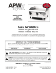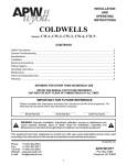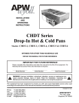
1
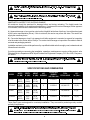
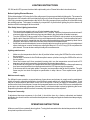
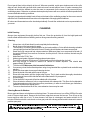
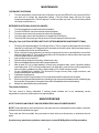
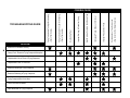
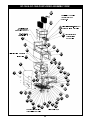
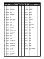
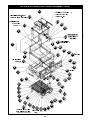
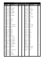
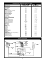
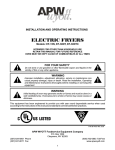
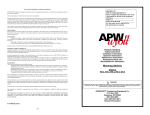
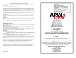
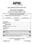
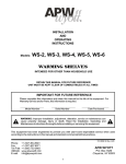
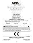
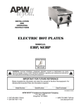
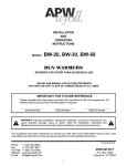
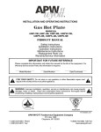
R INSTALLATION AND OPERATING INSTRUCTIONS Gas Fryer MODELS: GF-15H, GF-15HLP, GF-30H, GF-30HLP (US & Canadian units are convertible and are assembled for Natural Gas) (European units are not convertible and assembled for the appropriate gas) IMPORTANT FOR FUTURE REFERENCE Please complete this information and retain this manual for the life of the equipment. For Warranty Service and/or Parts, this information is required. Model Number Serial Number Date Purchased ! FOR YOUR SAFETY: Do not store or use gasoline or other flammable vapors and liquids in the vicinity of this or any other appliance. ! WARNING: Improper installation, operation, service or maintenance can cause property damage, injury or death. Read and understand these instructions thoroughly before positioning, installing, maintaining or servicing this equipment. ! ! P/N 88356-22 2/06 APW WYOTT Foodservice Equipment Company +1 (307) 634-5801 Phone +1 (307) 637-8071 Fax P.O. Box 1829 Cheyenne, WY 82003 1 +1 (800) 752-0863 Toll Free www.apwwyott.com CAUTION: These models are designed, built, and sold for commercial use. If these models are positioned so the general public can use the equipment, make sure that cautions, warnings, and operating instructions are clearly posted near each unit so that anyone using the equipment will use it correctly and not injure themselves or harm the equipment. ! ! WARNING: Improper installation, adjustment, alteration, service or maintenance can cause property damage, injury or death. Read the installation, operating and maintenance instructions thoroughly before installing or servicing this equipment. WARNING: Install per the spacing requirements listed in the installation section of this manual. We strongly recommend having a competent professional install the equipment. A licensed electrician should make the electrical connections and connect power to the unit. Local codes should always be used when connecting these units to electrical power. In the absence of local codes, use the latest version of the National Electrical Code. ! ! WARNING: For your safety do not store or use gasoline or other flammable vapors and liquids in the vicinity of this or any other appliance. Keep the area free and clear of combustibles. (See ANZI Z83. 14B, 1991). ! NOTICE: Instructions to be followed if anyone smells gas should be posted in a prominent place. These may be obtained from the gas supplier. ! ! ! ! ! GAS PRESSURE The appliance and it’s individual shutoff valve must be disconnected from the gas supply piping system during any pressure testing of that system at test pressures in excess of ½ psi (3.45 kPa). The appliance must be isolated from the gas supply piping system by closing it’s individual manual shut-off valve during any pressure testing of the gas supply piping system at test pressures equal to or less than ½ psi (3.45 kPa). ! ! WARNING: A factory authorized agent should handle all maintenance and repair. Before doing any maintenance or repair, contact APW Wyott. NOTICE: This product is intended for commercial use only. Not for household use. ! ! CAUTION: These models are designed, built, and sold for commercial use. If these models are ! ! positioned so the general public can use the equipment make sure that cautions, warnings, and operating instructions are clearly posted near each unit so that anyone using the equipment will use it correctly and not injure themselves or harm the equipment. WARNING: SHOCK HAZARD: Do not open any panels that require the use of tools. ! WARNING: Improper installation, operation, service or maintenance can cause property damage, injury or death. Read and understand these instructions thoroughly before positioning, installing, maintaining or servicing this equipment. ! WARNING: Keep the appliance free and clear from all combustible substances. In the event of gas odor, shut unit down at the main shut-off valve and contact the local gas company or gas supplier for service. 2 ! ! ! ! Congratulations on your purchase of APW Wyott commercial cooking or refrigeration equipment. APW Wyott takes pride in the design and quality of our products. When used as intended and with proper care and maintenance, you will experience years of reliable operation from this equipment. To ensure best results, it is important that you read and follow the instructions in this manual carefully. TABLE OF CONTENTS: ITEM PAGE Safety Precautions Specifications & Dimensions General Installation Instructions Lighting Instructions Operating Instructions Cleaning Maintenance 3 4 5 6 6 7 8 ITEM PAGE Service/Repair Troubleshooting Guide Parts Lists & Exploded Views Suggested Temperatures & Times Wiring Diagram Warranty 8 9 10 14 14 15 LOCATION OF DATA PLATE The data plate is located on the back side of the front panel. SAFETY PRECAUTIONS Before installing and operating this equipment be sure everyone involved in its operation are fully trained and are aware of all precautions. Accidents and problems can result by a failure to follow fundamental rules and precautions. The following words and symbols, found in this manual, alert you to hazards to the operator, service personnel or the equipment. The words are defined as follows: ! DANGER: This symbol warns of imminent hazard which will result in serious injury or death. ! ! WARNING: This symbol refers to a potential hazard or unsafe practice, which could result in serious injury or death. ! ! CAUTION: This symbol refers to a potential hazard or unsafe practice, which may result in minor or moderate injury or product or property damage. ! ! NOTICE: This symbol refers to information that needs special attention or must be fully understood even though not dangerous. ! GAS PRESSURE: This appliance is equipped with a gas pressure regulator that is built-in as part of the main control valve. The unit will be factory set at 3.5” of water column (9 mbar) at the manifold for Natural Gas. The unit will be factory set to 10” of water column (25 mbar) at the manifold for Propane Gas. This regulator may only be adjusted by a properly certified technician. ! WARNING: Do not obstruct either the air inlet (underneath unit) or the ventilation air (back of unit). Provisions must be provided to provide an adequate air supply to the fryer. 3 ! ! NOTICE: Canadian installation must comply with CSA-STANDARD C.22.2 Number 0 M1982 General Requirements-Canadian Electrical Code Part II, 109-M1981- Commercial Cooking Appliances. ! NOTICE: Local codes regarding installation vary greatly from one area to another. The National ! Fire Protection Association, Inc. states in its NFPA96 latest edition that local codes are Authority Having Jurisdiction when it comes to requirement for installation of equipment. Therefore, installation should comply with all local codes. ! IMMEDIATELY INSPECT FOR SHIPPING DAMAGE All containers should be examined for damage before and during unloading. The freight carrier has assumed responsibility for its safe transit and delivery. If equipment is received damaged, either apparent or concealed, a claim must be made with the delivering carrier. A) Apparent damage or loss must be noted on the freight bill at the time of delivery. It must then be signed by the carrier representative (Driver). If this is not done, the carrier may refuse the claim. The carrier can supply the necessary forms. B) Concealed damage or loss if not apparent until after equipment is uncrated, a request for inspection must be made to the carrier within 15 days. The carrier should arrange an inspection. Be certain to hold all contents and packaging material. Installation and start-up should be performed by a qualified installer who thoroughly read, understands and follows these instruction. If you have questions concerning the installation, operation, maintenance or service of this product, write Technical Service Department APW Wyott Foodservice Equipment Company, P.O. Box 1829, Cheyenne, WY 82003. ! CAUTION: All foodservice equipment should be operated by trained personnel only. Do not allow your customers to come in contact with any surface labeled CAUTiON HOT. Never pour cold water into heated unit. Never hold food below 140°F. ! SPECIFICATIONS AND DIMENSIONS WIDTH IN. (MM) DEPTH IN. (MM) HEIGHT IN. (MM) # OF BURNERS BTU/kW PER BURNER NATURAL GAS TOTAL BTU/kW HOUR GF-15H 26.25 (666.75) 12.00 (304.80) 20.38 (517.65) 3 13.333/3.9 40,000/11.72 3.5 (9) GF-15HLP 26.25 (666.75) 12.00 (304.80) 20.38 (517.65) 3 13.333/3.9 40,000/11.72 10 (25) GF-30H 26.25 (666.75) 20.00 (508) 20.38 (517.65) 6 15,000/4.4 90,000/26.38 3.5 (9) GF-30HLP 26.25 (666.75) 20.00 (508) 20.38 (517.65) 6 13,333/3.9 80,000/23.45 10 (25) MODEL W.C. IN. (’Mbar’) These Gas Fryers are designed for countertop installation. They are used for producing evenly cooked, perfectly fried potatoes. WARNING: This Fryer is restrained from tipping and splashing hot oil by using the 1/2 NDT gas ! inlet pipe. If a flexible inlet hose is used the unit must be restrained by other means. This Fryer should not be moved with liquid in the fry tank as serious burns can result. Liquid should be drained into a suitable container using the drain valve supplied located behind the front door. 4 ! GENERAL INSTALLATION INSTRUCTIONS Ensure gas supply and gas type, as shown on unit nameplate agree. Unit installation must conform with the National Fuel Gas Code, ANSI Z223.1-1996, the National Gas Installation Code, CAN/CGA-B149.1, or the Propane Installation Code, CAN/CGA-B149.2 as applicable and in accordance with local codes. Screw legs into the permanently fastened nuts on the four corners of the unit and tighten by hand. Level the unit by turning the adjustment screw at the bottom of each leg. Do not slide unit with legs mounted, lift if necessary to move unit. Pipe threading compound must be resistant to the action of liquefied petroleum gases. Caution: DO NOT use an open flame to check for leaks. Check all gas piping for leaks with a soap and water solution before operating unit. THESE UNITS ARE SUITABLE FOR INSTALLATION ON NON-COMBUSTIBLE SURFACES ONLY. Noncombustible clearances: 0" sides (0 mm) 0" rear (0 mm) Do not obstruct the flow of combustion and ventilation air, under the unit by the legs or behind the unit by the flue. Adequate clearance for air openings into the combustion chamber is required. Do not place objects between the bottom of the unit and the counter top. There must be adequate clearance for removal of the front panel. All major parts except the burners are removable thru the front if the gas line is disconnected. CANADIAN INSTALLATION MUST COMPLY WITH THE CANADIAN ELECTRICAL CODE, CSA C22.2 AS APPLICABLE. NOTICE: Local codes regarding installation vary greatly from one area to another. The National ! Fire Protection Association, Inc. states in its NFPA96 latest edition that local codes are Authority Having Jurisdiction when it comes to requirement for installation of equipment. Therefore, installation should comply with all local codes. ! European Community Installation Instructions: “THIS APPLIANCE MUST BE FITTED BY A COMPETENT PERSON. IN THE UK, CORGI REGISTERED INSTALLERS (INCLUDING THE REGIONS OF BRITISH GAS) UNDERTAKE TO WORK TO SAFE AND SATISFACTORY STANDARDS. THIS APPLIANCE MUST BE INSTALLED IN ACCORDANCE WITH THE GAS SAFETY (INSTALLATION AND USE) REGULATIONS AND THE RELEVANT BUILDING REGULATIONS / IEE. REGULATIONS. DETAILED RECOMMENDATIONS ARE CONTAINED IN THE FOLLOWING BRITISH STANDARD CODES OF PRACTICE - BS 6172, BS 5440 PART 2, BS 6891" "THIS APPLIANCE MUST BE INSTALLED IN ACCORDANCE WITH THE RULES IN FORCE” "MUST BE INSTALLED IN A WELL VENTILATED AREA. Ventilation requirements ie. B.S. 5440.” IMPORTANT: We strongly recommend having a competent professional install this equipment. Such a person should be familiar with local gas regulations. A gas company representative should approve the completed installation. 5 LIGHTING INSTRUCTIONS GF-30H and HLP Fryers are furnished with a pilot safety valve. Please follow the instructions below. Before Lighting Pilot and Burners Fill the fat tank about 3/4" below the full line with proper frying cornpound before lighting pilot. The reason for filling the tank 3/4" below the full line is that the frying corn pound will expand during the preheating process. If the frying compound expands above the full line, the frying compound may overflow out of the tank during the cooking process. The reason for adding fry compound in fry tank before lighting the pilot or burners is that the unit will be damaged if this is not done. Pilot Safety Valve Lighting Instructions 1. 2. 3. I 4. Turn on main gas supply to unit, on-off valve located under the unit. Turn the burner temperature control knob to "OFF" position. Open the front panel and wait at least 5 minutes to allow any gas which may have accumulated in the combustion chamber to escape. Turn the Off/Pilot/On valve control to Pilot. Depress the Off/Pilot/On valve control on the valve and light the pilot. Keep the Off/Pilot/On valve control depressed for at least 1-2 minutes after pilot has lit. f pilot does not stay lit, repeat this step. All valve controls and dials must be operated by hand. Never use pliers, wrenches or other tools to rotate valve control and temperature dial. If pilot flame needs to be adjusted, remove the pilot adjust cover screw and turn the inner adjustment screw clockwise or counter-clockwise to adjust pilot flame to 1/2" to 3/4" long (12/19 mm) above the pilot channel. This can be done while pilot stays lit to see flame size. Lighting main burners 1. 2. 3. 4. 5. Make sure the temperature dial is in the off position before turning the Off/Pilot/On valve control to the on position. Wait at least 5 minutes for the Pilot/thermopile to warm up before turning the Off/Pilot/On valve to the on position. Since the burners are lit from constantly burning pilot, turn the temperature control knob to 375 degrees to put the unit in operation; then adjust to any desired temperature. If the burners do not ignite, turn temperature dial to the off position and let the thermopile warm up for a few more minutes then turn the temperature dial to 375 degrees to put in operation. If the burners still do not ignite within 5 seconds, turn temperature dial to the off position. The pilot flame may be too short and adjust to specification in step 4 above. Then repeat burner ignition steps. Main burner air supply For efficient burner operation, a proper balance of gas volume and primary air supply must be maintained, which will result in complete combustion. Insufficient air supply results in a yellow streaming flame. There may be no obstructions to the bottom of the unit or the top flue. Primary air supply is controlled by an air shutter on the front-of each burner. Loosen the hexagonal head screw on front of the burner, and adjust the air shutter to just eliminate yellow tips of burner flame. Lock the air shutter in place by tightening the screw. Repeat this procedure with all burners if necessary. Adjustment may not be required. European Community If adjustment becomes necessary in the field, it should be done by a factory authorized and trained technician who should seal the screw after the adjustment to safeguard against unauthorized tampering by the end user. OPERATING INSTRUCTIONS All burners are lit from constantly burning pilots. Turning the thermostat to the desired temperature is all that is required to put the unit in service. 6 Do not permit fans to blow directly at the unit. Wherever possible, avoid open windows next to the unit's sides or back. Avoid wall type fans which create air cross-currents within a room. It is also necessary that sufficient air should be allowed to enter the room to compensate for the amount of air removed by any ventilating system. Otherwise, a subnormal atmospheric pressure will occur, which will effect operation and cause undesirable working conditions. A properly designed and installed hood will act as the heart of the ventilating system for the room or area in which the unit is installed and will leave the unit independent of changing draft conditions. All valves and thermostats must be checked periodically. Consult the authorized service representative in your area. CLEANING Initial Cleaning Always clean equipment thoroughly before first use. Clean the protective oil from the bright parts and interior of tank with a solution of washing soda or other grease dissolving material. Cleaning 1. 2. 3. Always turn unit off and allow it to cool completely before cleaning. Never clean unit by immersing it in water. The frequency of cleaning should depend on the load conditions. Set a definite cleaning schedule corresponding to how hard the kettle is used. Cleaning should be done at a least once a week. Strain the frying compound into a clean container. Make sure there is no compound left in tank. (If the tank is left empty for more than 2 minutes, shut the pilot off. If this is not done, the tank may be damaged.) Add water to the "FULL" line. Add any good grade of cleaner following cleaner instructions. Turn the thermostat to 250 degrees F. Let the heating unit bring the solution to a boil. Boil long enough to loosen or dissolve all varnish or carbon deposits. This should take approximately 30 minutes. Turn the unit off. Make sure pilot is turned off at this time. If necessary, clean the thermostat probes using a long-handled fiber or plastic brush and mild soap solution. Rinse with clean water to remove all cleaning mixture. Rinse the inside of the tank with 2 cups of vinegar. Rinse with clean water until the vinegar odor is gone. The fry tank must be thoroughly rinsed since even a trace of cleaner left inside the tank will contaminate the fry compound. Dry thoroughly. Cover the tank if compound will not be added until a future date. Clean all exterior surfaces of unit on a regular basis with a damp cloth. Thin films of oil subjected to frying temperatures quickly form into gummy consistency. In order to avoid these gum formations, clean the surfaces on a regular basis. To remove discolorations or oil film, a non-abrasive cleaner may be used. 4. 5. 6. 7. 8. 9. 10. 11. 12. 13. 14. 15. 16. 17. Cleaning Burner Air Shutters Burner ports and burner air shutters must be kept clean. To remove burners, turn off the Off/Pilot/On valve control. Remove back panel. Remove the hold down strap that secures the burners. Then lift up on the burner end then slide out of unit. To clean burners, boil them in a detergent and water solution for 15 minutes. Either brush with a wire brush or clean gas ports with a sharp pointed metal instrument to ensure positive open ports. ! CAUTION : Clean the regulator at least once a month. Make sure the vent opening is open and not blocked in any way. Failure to do so will cause variations in pressure. Your unit will not function as well and it could shorten the life of the product. 7 ! MAINTENANCE OVER NIGHT SHUTDOWN 1. Turn the temperature control knob to the off position. Or turn the Off/Pilol/On valve control to Pilot if you wish not to change the temperature setting. (The pilot flame alone will keep the frying compound temperature to 130-145 degrees F. when not under any load. This will shorten preheat time when turned back on.) EXTENDED SHUTDOWN (4 DAYS OR LONGER) 1. 2. 3. 4. 5. Turn the temperature control knob to the off position. Turn the Off/Pifot/On valve control knob to the off position. Turn the manual control valve under the unit to the off position. Turn the supply valve to the off position (not supplied by APW Wyott). The entire flue duct opening on the top rear of unit must always be left uncovered. Filling Fry Tank (CAUTION: NEVER LIGHT PILOT OR TURN BURNERS ON WITH EMPTY TANK) 1. 2. 3. 4. 5. 6. 7. 8. 9. 10. 11. Fill the fry tank approximately 3/4" below the full line. The fry compound will expand as it is heated. Heat the fry compound to 375 degrees for 20 minutes then check the level. Add or decrease amount of fry compound so it lines up with the full line. When using solid frying compound, put enough compound in fry tank so at least half or more of the tank has compound in it. Then set the temperature to 200 degrees on dial and allow the compound to liquefy. Add to adjust compound level. Use a quality frying compound. Filter the frying compound frequently, at least once a day. Skim out food particles frequently with a strainer/skimmer. Add at least 15% (of fry tank capacity) of fresh frying compound daily (more if possible) without overloading tank. If 15% of frying compound is not used daily, remove some of the compound for other use (gravy, griddle frying, etc.) to permit adding 15% of fresh compound daily. Do not overload the fry baskets. This will result in longer recovery time, longer cook time, and compound absorption into the product. Prepare the food properly. Keep salt out of the frying compound. Do not salt foods with the basket above the kettle. Ensure a good thermostat operation by checking frying compound temperature with a reliable frying thermometer. Temperature of compound should be comparable to thermostat setting. Keep the fry tank and thermo-probes clean. Thermostat Calibration The fryer control is factory calibrated. If cooking results indicate unit is not maintaining correct temperatures, consult an authorized service representative. SERVICE I REPAIR NOTE: THIS APPLIANCE MUST ONLY BE SERVICED BY AN AUTHORIZED AGENT. NOTE: Parts protected by the manufacturer or his agent are not to be adjusted by the installer, unless the installer is an authorized service agent. These units are field convertible. Any conversion to these units must be done by an authorized service agent. If you have any questions or problems contact your nearest APW Wyott Service Representative. 8 PROBLEM Excessive & Premature Foaming Greasy Food / Excessive Frying Compound Absorption Objectionable Odor or Flavor of Frying Compound Objectionable Flavor of Fried Food Excessive Smoking of Frying Compound Excessive Darkening of Frying Compound Frying Compound Won’t Hold Heat Food Crust Color Not Brown Rapid Breakdown of Frying Compound (Due to salt or other foreign material) Contamination of Fryer Compound Improper Preparation of Food Inadequate Frying Compound Turnover High Moisture Content in Food Being Fried Improper Draining of Food After Frying Overloading Fryer (Check Thermostat) Frying Temperature Too Low/Overheating (Check Thermostat) TROUBLESHOOTING GUIDE Frying Temperature Too High/Overheating POSSIBLE CAUSE GF-15H & GF-15HLP EXPLODED ASSEMBLY VIEW 26 Seal All NPTS w/Teflon Tape or Leak Lock (10451-00) 24 32 38 Seal inside seam w/ Red High Temp RTV Seal w/Silicone Extrusion Item 17 17 30 28 35 45 37 Thermostat Probe Connect Wires 54 53 Clip Pins Flush w/Washers Inner Liner 7 27 16 23 22 36 46 2 41 Connect Wires to Gas Valve to Gas Valve 10 1 High Limit Thermo-probe 52 48 19 39 6 9 29 51 49 47 40 50 3 55 4 31 14 25 18 43 12 42 5 8 33 11 56 21 20 13 15 Pilot Supply Tube Connect Wires of Pilot/ Thermopile to Gas Valve 10 34 GF-15H & GF-15HLP PARTS LIST ITEM P/N 1 81349-00 2 DESCRIPTION ITEM P/N Screw 36 29 218161-35 Front Panel 1 218161-37 Back Panel 1 30 217730-19 Drain Tube 1 3 218161-46 Side Insulation 2 31 217730-04 Drain Tube 1 4 218161-34 Bottom Main 1 32 14731-05 High Limit 1 5 20658-41 Burner 2 33 20925-94 Reducer 1 6 218161-44 Strap Holdown 1 34 218161-48 Manifold 1 7 218161-15 Inner Liner 1 35 85023-00 Snap Washer 3 8 86320-00 Leg 4 36 20344-00 Elbow 1 9 20658-40 Burner, Crossover 1 37 14731-07 Thermostat 1 10 218161-25 Body Weldment 1 38 218163-69 Knob 1 11 20343-00 Elbow 1 39 81925-00 Screw 4 12 20656-12 valve 1 40 218161-63 Label, Champion 1 13 217730-41 Drain Support 1 41 85053-00 Washer 3 14 218161-39 Tube, Vertical 1 42 218161-66 Bracket, Indicator 1 15 20661-80 Pilot 1 43 81320-00 Screw 2 20668-83 Pilot Orifice For LP 1 44 20925-17 Plug 1 16 218161-47 Front Insulation 3 45 438131-03 Label 2 17 23432-00 Extrusion 1 46 88610-00 Label 1 18 20656-38 Valve 1 47 88253-10 Label 1 20927-16 LP Conversion Kit 1 48 88253-12 Label 1 19 20925-30 Elbow 1 49 88326-00 Label 1 20 218161-40 Pilot Supply Tube 1 50 88253-00 Decal 1 21 120668-51 Orifice GF-15H 3 51 88253-11 Label 1 20668-57 Orifice GF-15HLP 3 52 88371-31 Label 1 22 218161-38 Tube, Horizontal 1 53 87050-00 Magnet 2 23 81423-00 Screw 4 54 438131-49 Label 2 24 218161-10 Fry Tank 1 55 218161-68 Bottom, Heat Shield 1 25 20691-00 Burner Fitting 3 56 83530-00 Rivet 8 26 31012-12 Basket, 1/2 Size 2 27 218161-45 Rear Insulation 1 28 218161-55 Ball Valve 1 11 DESCRIPTION QUAN QUAN GF-30H & GF-30HLP EXPLODED ASSEMBLY VIEW 14 High Limit Thermo-probe Connect Wires to Gas Valve Seal All NPTS w/Teflon Tape (29376) or Leak 21 Lock(10451-00) 27 Seal inside seam w/ Red High 10 Temp RTV 28 3 31 24 5 1 Clip Pins Flush w/Washer 38 2 50 9 Seal w/Silicone Extrusion Item 9 49 34 35 4 37 41 40 6 4 36 39 53 20 54 52 Far Side 44 45 22 18 43 25 13 56 47 15 57 8 55 58 11 17 12 19 26 23 7 33 Connect Wires of Pilot/ Thermopile to Gas Valve Pilot Supply Tube 12 46 16 30 29 32 51 55 48 Far Side GF-30H & GF-30HLP PARTS LIST ITEM P/N 1 81349-00 2 DESCRIPTION ITEM P/N Screw 35 30 20656-12 Valve 1 218163-45 Rear Insulation 1 31 218161-55 Ball Valve 1 3 218163-37 Back Panel 1 32 218150-86 Drain Support 1 4 218161-46 Side Insulation 4 33 217730-04 Drain Tube 1 5 218163-25 Body Assembly 1 34 87050-00 Magnet 2 6 218163-15 Inner liner 1 35 218163-35 Front Panel 1 7 218163-34 Panel, Bottom 1 36 88371-31 Label 1 8 86320-00 Leg 4 37 218163-63 Label, Champ 1 9 23432-00 Extrusion 1 38 438131-03 Label 2 10 218163-10 Fry Tank 1 39 88253-10 Label 1 11 20658-41 Burner 3 40 88253-12 Label 1 12 20656-38 Valve 1 41 88610-00 Label 1 20927-16 LP Conversion Kit 1 42 218161-66 Bracket, Indic 1 13 20658-40 Burner, Crossover 3 43 218163-39 Vertical Tube 1 14 31012-32 Basket 2 44 81423-00 Screw 4 15 218163-44 Holdown 1 45 81925-00 Screw 4 16 218163-48 Manifold 1 46 81697-00 Screw 2 17 20925-95 Reducer 1 47 85053-00 Washer 5 18 20925-30 Elbow 1 48 81320-00 Screw 2 19 218163-40 Tube, Pilot 1 49 438131-49 Label 2 20 218163-47 Front Insulation 3 50 85023-00 Washer 3 21 14731-05 High Limit Probe 1 51 20925-17 Plug 1 22 218163-38 Tube, Horizontal 1 52 88326-00 Label 1 23 20668-51 Orifice GF-30H 6 53 88253-00 Decal 1 20668-57 Orifice GF-30HLP 6 54 88253-11 Label 1 24 14731-07 Thermostat 1 55 83530-00 Rivet 10 25 20691-00 Burner Fitting 6 56 218163-62 Bracket, Pilot 1 26 20661-80 Pilot 1 57 218163-68 Heat Shield 1 20668-83 Pilot Orifice For LP 1 58 20344-00 Elbow 1 27 14798-18 Knob 1 28 218163-21 Drain Tube 1 29 20343-00 Street Elbow 1 13 DESCRIPTION QUAN QUAN SUGGESTED TEMPERATURES & TIMES FOOD TYPE CONTROL SETTING TIME (IN DEGREES F) (IN MINUTES) 375 375 1½-2 2-2½ 350 350 350 5-8 5-8 5-8 375 350 350 350 350 1-2 2-3 2-3 5 - 10 1-2 325 350 325-350 325 10 - 15 7 - 10 3-5 9 - 10 DOUGHNUTS Cake Type Yeast Raised MEAT Cutlets (less than 112" thick) Chicken Fried Steak Chops (very lean) MISCELLANEOUS Chinese Noodles Croquettes French Toast Glazed Cinnamon Apples French Fried Sandwiches POULTRY Chicken (large pieces) Chicken (small pieces) Chicken (pre-cooked) Turkey (small pieces) SEAFOOD Fish Cakes Clams Fillets (small) Oysters Scallops Shrimp Smelts VEGETABLES Eggplant Onion Rings Potatoes (112" strips, one-operation) Potatoes (blanch) Potatoes (brown) Potatoes (julienne) 350 350 350 350 350 350 350 2-3 1-3 3-5 2-5 3-5 4-6 4-6 350 350 350 350 350 350 5-7 3-5 6-9 4-6 2-3 3-5 WIRING DIAGRAM Normally 14731-07 Closed 218161-64 Normally 14731-07 Open Common 11195-12 20661-80 20656-38 11260-09 11195-06 14 APW WYOTT EQUIPMENT LIMITED WARRANTY APW Wyott Foodservice Equipment Company warrants it's equipment against defects in materials and workmanship, subject to the following conditions: This warranty applies to the original owner only and is not assignable. Should any product fail to function in its intended manner under normal use within the limits defined in this warranty, at the option of APW Wyott such product will be repaired or replaced by APW Wyott or its Authorized Service Agency. APW Wyott will only be responsible for charges incurred or service performed by its Authorized Service Agencies. The use of other than APW Wyott Authorized Service Agencies will void this warranty and APW Wyott will not be responsible for such work or any charges associated with same. The closest APW Wyott Authorized Service Agent must be used. This warranty covers products shipped into the 48 contiguous United States, Hawaii, metropolitan areas of Alaska and Canada. There will be no labor coverage for equipment located on any island not connected by roadway to the mainland. Warranty coverage on products used outside the 48 contiguous United States, Hawaii, and metropolitan areas of Alaska and Canada may vary. Contact the international APW Wyott distributor, dealer, or service agency for details. Time Period One year for parts and one year for labor, effective from the date of purchase by the original owner. The Authorized Service Agency may, at their option, require proof of purchase. Parts replaced under this warranty are warranted for the un-expired portion of the original product warranty only. Exceptions *Gas/Electric Cookline: Models GCB, GCRB, GF, GGM, GGT, CHP-H, EF, EG, EHP. Three (3) Year Warranty on all component parts, except switches and thermostats. (2 additional years on parts only. No labor on second or third year.) *Broiler Briquettes, Rock Grates, Cooking Grates, Burner Shields, Fireboxes: *Heat Strips: *Glass Windows, Doors, Seals, Rubber Seals, Light Bulbs: Models FD, FDL, FDD, FDDL. 90 Day Material Only. No Labor. Two (2) Year Warranty on element only. 90 Day Material Only. No labor second year. No Labor. In all cases, parts covered by extended warranty will be shipped FOB the factory after the first year. Portable Carry In Products Equipment weighing over 70 pounds or permanently installed will be serviced on-site as per the terms of this warranty. Equipment weighing 70 pounds or under, and which is not permanently installed, i.e. with cord and plug, is considered portable and is subject to the following warranty handling limitations. If portable equipment fails to operate in its intended manner on the first day of connection, or use, at APW Wyott's option or its Authorized Service Agency, it will be serviced on site or replaced. From day two through the conclusion of this warranty period, portable units must be taken to or sent prepaid to the APW Wyott Authorized Service Agency for in-warranty repairs. No mileage or travel charges are allowed on portable units after the first day of use. If the customer wants on-site service, they may receive same by paying the travel and mileage charges. Exceptions to this rule: (1) countertop warmers and cookers, which are covered under the Enhanced Warranty Program, and (2) toasters or rollergrills which have in store service. Exclusions The following conditions are not covered by warranty: *Equipment failure relating to improper installation, improper utility connection or supply and problems due to ventilation. *Equipment that has not been properly maintained, calibration of controls, adjustments, damage from improper cleaning and water damage to controls. *Equipment that has not been used in an appropriate manner, or has been subject to misuse or misapplication, neglect, abuse, accident, alteration, negligence, damage during transit, delivery or installation, fire, flood, riot or act of god. *Equipment that has the model number or serial number removed or altered. If the equipment has been changed, altered, modified or repaired by other than an Authorized Service Agency during or after the warranty period, then the manufacturer shall not be liable for any damages to any person or to any property, which may result from the use of the equipment thereafter. This warranty does not cover services performed at overtime or premium labor rates. Should service be required at times which normally involve overtime or premium labor rates, the owner shall be charged for the difference between normal service rates and such premium rates. APW Wyott does not assume any liability for extended delays in replacing or repairing any items beyond its control. In all cases, the use of other than APW Wyott Authorized OEM Replacement Parts will void this warranty. This equipment is intended for commercial use only. Warranty is void if equipment is installed in other than commercial application. Water Quality Requirements Water supply intended for a unit that has in excess of 3.0 grains of hardness per gallon (GPG) must be treated or softened before being used. Water containing over 3.0 GPG will decrease the efficiency and reduce the operation life of the unit. Note: Product failure caused by liming or sediment buildup is not covered under warranty. THE FOREGOING WARRANTY IS IN LIEU OF ANY AND ALL OTHER WARRANTIES EXPRESSED OR IMPLIED INCLUDING ANY IMPLIED WARRANTY OF MERCHANTABILITY OR FITNESS FOR PARTICULAR PURPOSES AND CONSTITUTES THE ENTIRE LIABILITY OF APW WYOTT. IN NO EVENT DOES THE LIMITED WARRANTY EXTEND BEYOND THE TERMS STATED HEREIN. 9/05 15 R APW WYOTT Foodservice Equipment Company +1 (307) 634-5801 Phone +1 (307) 637-8071 Fax P.O. Box 1829 Cheyenne, WY 82003 16 +1 (800) 752-0863 Toll Free www.apwwyott.com