1
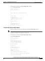
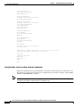
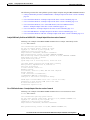
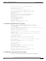
C H A P T E R
4
Configuring the PA-FE-TX or PA-FE-FX
To continue your PA-FE-TX or PA-FE-FX port adapter installation, you must configure the Fast Ethernet
interface. The instructions that follow apply to all supported platforms. Minor differences between the
platforms—with Cisco IOS software commands—are noted.
This chapter contains the following sections:
•
Using the EXEC Command Interpreter, page 4-1
•
Configuring the Interfaces, page 4-2
•
Checking the Configuration, page 4-5
Using the EXEC Command Interpreter
You modify the configuration of your router through the software command interpreter called the EXEC
(also called enable mode). You must enter the privileged level of the EXEC command interpreter with
the enable command before you can use the configure command to configure a new interface or change
the existing configuration of an interface. The system prompts you for a password if one has been set.
The system prompt for the privileged level ends with a pound sign (#) instead of an angle bracket (>).
At the console terminal, use the following procedure to enter the privileged level:
Step 1
At the user-level EXEC prompt, enter the enable command. The EXEC prompts you for a
privileged-level password as follows:
Router> enable
Password:
Step 2
Enter the password (the password is case sensitive). For security purposes, the password is not displayed.
When you enter the correct password, the system displays the privileged-level system prompt (#):
Router#
To configure the new interfaces, proceed to the “Configuring the Interfaces” section on page 4-2.
Cisco PA-FE-TX and Cisco PA-FE-FX Fast Ethernet 100BaseT Port Adapter Installation and Configuration
OL-2899-03
4-1
Chapter 4
Configuring the PA-FE-TX or PA-FE-FX
Configuring the Interfaces
Configuring the Interfaces
After you verify that the new PA-FE-TX or PA-FE-FX is installed correctly (the enabled LED goes on),
use the privileged-level configure command to configure the new interfaces. Have the following
information available:
•
Protocols you plan to route on each new interface
•
IP addresses, if you plan to configure the interfaces for IP routing
•
Bridging protocols you plan to use
If you installed a new PA-FE-TX or PA-F-FX or if you want to change the configuration of an existing
interface, you must enter configuration mode to configure the new interfaces. If you replaced a
PA-FE-TX or PA-FE-FX that was previously configured, the system recognizes the new interfaces and
brings each of them up in their existing configuration.
For a summary of the configuration options available and instructions for configuring interfaces on a
PA-FE-TX or PA-FE-FX, refer to the appropriate configuration publications listed in the “Related
Documentation” section on page viii.
You execute configuration commands from the privileged level of the EXEC command interpreter, which
usually requires password access. Contact your system administrator, if necessary, to obtain password
access. (See the “Using the EXEC Command Interpreter” section on page 4-1 for an explanation of the
privileged level of the EXEC.)
This section contains the following subsections:
•
Performing a Basic Configuration, page 4-2
•
Configuring PA-FE-TX or PA-FE-FX Transmission Mode, page 4-4
•
Configuring PA-FE-TX or PA-FE-FX Media Type, page 4-4
Performing a Basic Configuration
Following are instructions for a basic configuration: enabling an interface and specifying IP routing. You
might also need to enter other configuration subcommands, depending on the requirements for your
system configuration and the protocols you plan to route on the interface. For complete descriptions of
configuration subcommands and the configuration options available for interfaces, refer to the
appropriate software documentation.
In the following procedure, press the Return key after each step unless otherwise noted. At any time you
can exit the privileged level and return to the user level by entering disable at the prompt as follows:
Router# disable
Router>
Step 1
At the privileged-level prompt, enter configuration mode and specify that the console terminal is the
source of the configuration subcommands, as follows:
Router# configure terminal
Enter configuration commands, one per line. End with CNTL/Z.
Router(config)#
Cisco PA-FE-TX and Cisco PA-FE-FX Fast Ethernet 100BaseT Port Adapter Installation and Configuration
4-2
OL-2899-03
Chapter 4
Configuring the PA-FE-TX or PA-FE-FX
Configuring the Interfaces
Step 2
The following examples explain how to configure the Fast Ethernet interface:
•
For the Cisco 7100 series, Cisco 7200 series, and the Cisco uBR7200 series, at the prompt specify
the first interface to configure by entering the subcommand interface, followed by the type
(fastethernet) and slot/interface (port adapter slot number and interface number). The example that
follows is for the first interface of the port adapter in slot 4:
Router(config)# interface fastethernet 4/0
Note
•
For the Cisco 7206VXR and Cisco 7206 router shelves in the Cisco AS5800 Universal Access
Server, the interface specified in the above example would include a shelf number. For example,
the command interface fastethernet 5/4/0 would specify the first Fast Ethernet interface of the
port adapter in slot 4 of router shelf 5.
For the Cisco 7301 router, the Cisco 7401ASR router, and the Cisco 7304 PCI Port Adapter Carrier
Card in a Cisco 7304 router, at the prompt specify the first interface to configure by entering the
subcommand interface, followed by the type (fastethernet) and slot/interface (port adapter slot
number and interface number). The example that follows is for the first interface of the port adapter
in slot 1:
Router(config)# interface fastethernet 1/0
•
For the VIP, at the prompt specify the first interface to configure by entering the subcommand
interface, followed by the type (fastethernet) and slot/port-adapter/interface. The example that
follows is for the first interface of the first port adapter, on a VIP in interface processor slot 1:
Router(config)# interface fastethernet 1/0/0
•
For the Catalyst RSM/VIP2, at the prompt specify the first interface to configure by entering the
subcommand interface, followed by the type (fastethernet) and port-adapter/interface. The
example that follows is for the first interface of the first port adapter, on a Catalyst RSM/VIP2:
Router(config)# interface fastethernet 0/0
Step 3
If IP routing is enabled on the system, you can assign an IP address and subnet mask to the interface with
the ip address configuration subcommand, as in the following example:
Router(config-if)# ip address 10.0.0.0 10.255.255.255
Step 4
Add any additional configuration subcommands required to enable routing protocols and set the
interface characteristics.
Step 5
Change the shutdown state to up and enable the interface as follows:
Router(config-if)# no shutdown
Step 6
Configure additional interfaces as required.
Step 7
After including all of the configuration commands to complete your configuration, press Ctrl-Z—hold
down the Control key while you press Z—or enter end or exit to exit configuration mode and return to
the EXEC command interpreter prompt.
Step 8
Write the new configuration to NVRAM as follows:
Router# copy running-config startup-config
[OK]
Router#
This completes the procedure for creating a basic configuration.
Cisco PA-FE-TX and Cisco PA-FE-FX Fast Ethernet 100BaseT Port Adapter Installation and Configuration
OL-2899-03
4-3
Chapter 4
Configuring the PA-FE-TX or PA-FE-FX
Configuring the Interfaces
Configuring PA-FE-TX or PA-FE-FX Transmission Mode
Half-duplex operation is the default transmission mode for the PA-FE-TX or PA-FE-FX. Use the
full-duplex command to configure full-duplex operation for the PA-FE-TX or PA-FE-FX as follows:
Router# configure terminal
Enter configuration commands, one per line. End with CNTL/Z.
Router(config)#
Router(config)# interface fastethernet 4/0
Router(config-if)# full-duplex
Ctrl-z
Use the show interfaces fastethernet command to verify that the 4/0 Fast Ethernet interface is now
configured for full-duplex operation as follows:
Router# show interfaces fastethernet 4/0
FastEthernet 4/0 is administratively up, line protocol is up
(display text omitted)
Encapsulation ARPA, loopback not set, keepalive not set, fdx, 100BaseTX
Use the no full-duplex command to return the interface to half-duplex operation as follows:
Router# configure terminal
Enter configuration commands, one per line. End with CNTL/Z.
Router(config)# interface fastethernet 4/0
Router(config-if)# no full-duplex
Ctrl-z
Router#
Use the show interfaces fastethernet command to verify that the 4/0 Fast Ethernet interface is now
configured for half-duplex operation as follows:
Router# show interfaces fastethernet 4/0
FastEthernet2/0 is administratively up, line protocol is up
(display text omitted)
Encapsulation ARPA, loopback not set, keepalive not set, hdx, 100BaseTX
(display text omitted)
To check the interface configuration using show commands, proceed to the “Checking the
Configuration” section on page 4-5
Note
When you enter the show interfaces fastethernet command using Cisco IOS Release 11.1(10) or later,
or Release 11.2(4) or later with updated Cisco hardware, the “overrun” field is always zero.
If you use this command because you are troubleshooting potential network problems, you may be
expecting to see a number in the overrun field.
Configuring PA-FE-TX or PA-FE-FX Media Type
The RJ-45 receptacle is the default media type for the PA-FE-TX and the SC receptacle (for fiber-optic
connections) is the default media type for the PA-FE-FX. Use the media-type mii command to configure
the MII receptacle as the media type for the PA-FE as follows:
Router# configure terminal
Enter configuration commands, one per line. End with CNTL/Z.
Router(config)# interface fastethernet 4/0
Router(config-if)# media-type mii
Ctrl-z
Cisco PA-FE-TX and Cisco PA-FE-FX Fast Ethernet 100BaseT Port Adapter Installation and Configuration
4-4
OL-2899-03
Chapter 4
Configuring the PA-FE-TX or PA-FE-FX
Checking the Configuration
Router# show interface fastethernet 4/0
FastEthernet3/0/0 is administratively up, line protocol is up
(display text omitted)
Encapsulation ARPA, loopback not set, keepalive not set, hdx, MII
(display text omitted)
Use the media-type 100 command to return the media type for the PA-FE-TX or PA-FE-FX to the RJ-45
receptacle or SC receptacle.
To check the interface configuration using show commands, proceed to the “Checking the
Configuration” section on page 4-5.
Checking the Configuration
After configuring the new interface, use the show commands to display the status of the new interface
or all interfaces, and use the ping command to check connectivity. This section includes the following
subsections:
•
Using show Commands to Verify the Interface Status, page 4-5
•
Using the ping Command to Verify Network Connectivity, page 4-22
Using show Commands to Verify the Interface Status
This section demonstrates how you can use the show commands to verify that interfaces are configured
and operating correctly and that the port adapter appears in them correctly. Sample displays of the output
of selected show commands appear in the sections that follow. For complete command descriptions and
examples, refer to the publications listed in the “Related Documentation” section on page viii.
If an interface is shut down and you configured it as up, or if the displays indicate that the hardware is
not functioning properly, ensure that the interface is properly connected and terminated. If you still have
problems bringing up the interface, contact a service representative for assistance. This section includes
the following subsections:
•
Using the show controllers Commands, page 4-6
•
Using the show protocols Command, page 4-6
•
Using the show running-config Command, page 4-6
•
Using the show startup-config Command, page 4-7
•
Using the show version or show hardware Commands, page 4-8
•
Using the show diag Command, page 4-13
•
Using the show interfaces Command, page 4-17
Choose the subsection appropriate for your system. Proceed to the “Using the ping Command to Verify
Network Connectivity” section on page 4-22 when you have finished using the show commands.
Cisco PA-FE-TX and Cisco PA-FE-FX Fast Ethernet 100BaseT Port Adapter Installation and Configuration
OL-2899-03
4-5
Chapter 4
Configuring the PA-FE-TX or PA-FE-FX
Checking the Configuration
Using the show controllers Commands
Display all the current interface processors and their interfaces using the show controllers command.
Note
The outputs that appear in this document may not match the output you receive when running these
commands. The outputs in this document are examples only.
The following is an example of the show controllers command:
Router# show controllers
MEMD at 40000000, 2097152 bytes (unused 3360, recarves 1, lost 0)
RawQ 48000100, ReturnQ 48000108, EventQ 48000110
BufhdrQ 48000128 (2900 items), LovltrQ 48000140 (5 items, 2016 bytes)
IpcbufQ 48000150 (16 items, 4096 bytes)
IpcbufQ_classic 48000148 (8 items, 4096 bytes)
3570 buffer headers (48002000 - 4800FF10)
pool0: 9 buffers, 256 bytes, queue 48000130
pool1: 344 buffers, 1536 bytes, queue 48000138
pool2: 284 buffers, 4544 bytes, queue 48000158
pool3: 4 buffers, 4576 bytes, queue 48000160
slot2: VIP2, hw 2.4, sw 22.20, ccb 5800FF40, cmdq 48000090
software loaded from flash slot0:vip2_22-20.atmdx.191897
IOS (tm) VIP Software (SVIP-DW-M), Experimental Version 11.3
ROM Monitor version 17.0
ATM2/0/0, applique is DS3 (45Mbps)
gfreeq 48000158, lfreeq 48000168 (4544 bytes), throttled 0
rxlo 4, rxhi 284, rxcurr 1, maxrxcurr 5
txq 48001A00, txacc 48001A02 (value 284), txlimit 284
Using the show protocols Command
Display protocols configured for the entire system and for specific interfaces using the show protocols
command.
Note
The outputs that appear in this document may not match the output you receive when running these
commands. The outputs in this document are examples only.
The following is an example of the show protocols command:
Router# show protocols
line protocol is up
Router#
Using the show running-config Command
Display the running configuration file using the show running-config command.
Note
The outputs that appear in this document may not match the output you receive when running these
commands. The outputs in this document are examples only.
Cisco PA-FE-TX and Cisco PA-FE-FX Fast Ethernet 100BaseT Port Adapter Installation and Configuration
4-6
OL-2899-03
Chapter 4
Configuring the PA-FE-TX or PA-FE-FX
Checking the Configuration
The following is an example of the show running-config command:
Router# show running-config
Building configuration...
Current configuration:
!
!
!
user add admin uid 0 capability admin-access
!
!
!
hostname CR4430
!
interface ethernet 0
ip address 10.2.2.8 255.255.255.0
ip broadcast-address 10.2.2.255
exit
!
interface ethernet 1
exit
!
ip default-gateway 10.2.2.1
ip name-server 10.2.2.6
ip route 0.0.0.0 0.0.0.0 10.2.2.1
Using the show startup-config Command
Display the configuration stored in the NVRAM using the show startup-config command.
Note
The outputs that appear in this document may not match the output you receive when running these
commands. The outputs in this document are examples only.
The following is an example of the show startup-config command:
Router# show startup-config
Building configuration...
Current configuration:
!
version 12.0
service timestamps debug uptime
service timestamps log uptime
no service password-encryption
!
hostname rp-3640-2b
!
ip subnet-zero
!
ip audit notify log
ip audit po max-events 100
!
crypto isakmp policy 1
hash md5
authentication pre-share
crypto isakmp key cisco123 address 95.95.95.2
!
crypto ipsec transform-set rtpset esp-des esp-md5-hmac
!
crypto map rtp 1 ipsec-isakmp
Cisco PA-FE-TX and Cisco PA-FE-FX Fast Ethernet 100BaseT Port Adapter Installation and Configuration
OL-2899-03
4-7
Chapter 4
Configuring the PA-FE-TX or PA-FE-FX
Checking the Configuration
set peer 95.95.95.2
set transform-set rtpset
match address 115
!
interface Ethernet0/0
ip address 98.98.98.1 255.255.255.0
no ip directed-broadcast
!
interface Ethernet0/1
ip address 99.99.99.2 255.255.255.0
no ip directed-broadcast
no ip route-cache
no ip mroute-cache
crypto map rtp
!
interface Ethernet0/2
no ip address
no ip directed-broadcast
shutdown
!
interface Ethernet0/3
no ip address
no ip directed-broadcast
shutdown
!
ip classless
ip route 0.0.0.0 0.0.0.0 99.99.99.1
no ip http server
!
access-list 115 permit ip 98.98.98.0 0.0.0.255 10.103.1.0 0.0.0.255
access-list 115 deny ip 98.98.98.0 0.0.0.255 any
!
line con 0
transport input none
line aux 0
line vty 0 4
login
!
end
Using the show version or show hardware Commands
Display the configuration of the system hardware, the number of each interface type installed, the Cisco
IOS software version, the names and sources of configuration files, and the boot images, using the show
version (or show hardware) command.
Note
The outputs that appear in this document may not match the output you receive when running these
commands. The outputs in this document are examples only.
Cisco PA-FE-TX and Cisco PA-FE-FX Fast Ethernet 100BaseT Port Adapter Installation and Configuration
4-8
OL-2899-03
Chapter 4
Configuring the PA-FE-TX or PA-FE-FX
Checking the Configuration
The following sections offer some platform-specific output examples using the show version command:
•
Catalyst 5000 Family Switches with RSM/VIP2—Example Output of the show version Command,
page 4-9
•
Cisco 7000 Series Routers—Example Output of the show version Command, page 4-9
•
Cisco 7100 Series Routers—Example Output of the show version Command, page 4-10
•
Cisco 7200 Series Routers, Cisco 7200 VXR Routers, and Cisco uBR7200 Series
Routers—Example Output of the show version Command, page 4-10
•
Cisco 7301 Routers—Example Output of the show version Command, page 4-11
•
Cisco 7401ASR Routers—Example Output of the show version Command, page 4-11
•
Cisco 7500 Series Routers with VIP—Example Output of the show version Command, page 4-12
Catalyst 5000 Family Switches with RSM/VIP2—Example Output of the show version Command
Following is an example of the show version command from a Catalyst 5000 family switch:
Router# show version
Cisco Internetwork Operating System Software
IOS (tm) GS Software (RSP-A), Version 11.1(6)CA
Copyright (c) 1986-1995 by cisco Systems, Inc.
Compiled Fri 06-Oct-95 12:22 by mpo
Image text-base: 0x600088A0, data-base: 0x605A4000
ROM: System Bootstrap, Version 5.3(16645) RELEASED SOFTWARE
ROM: GS Bootstrap Software (RSP-BOOT-M), Version 11.1(6)CA, RELEASED SOFTWARE
honda uptime is 4 hours, 22 minutes
System restarted by reload
System image file is “slot0:rsp-a111-1”, booted via slot0
cisco RSP2 (R4600) processor with 32768K bytes of memory.
R4600 processor, Implementation 32, Revision 2.0
Last reset from power-on
G.703/E1 software, Version 1.0.
Bridging software.
X.25 software, Version 2.0, NET2, BFE and GOSIP compliant.
Chassis Interface.
1 VIP2 controllers (1 FastEthernet).
1 FastEthernet/IEEE 802.3 interfaces.
125K bytes of non-volatile configuration memory.
20480K bytes of Flash PCMCIA card at slot 0 (Sector size 128K).
8192K bytes of Flash internal SIMM (Sector size 256K).
No slave installed in slot 6.
Configuration register is 0x2
Cisco 7000 Series Routers—Example Output of the show version Command
Following is an example of the show version command from a Cisco 7000 series router:
Router# show version
Cisco Internetwork Operating System Software
IOS (tm) C2600 Software (C2600-IS-M), Version 12.0(7)T, RELEASE SOFTWARE (fc2)
Copyright (c) 1986-1999 by cisco Systems, Inc.
Compiled Tue 07-Dec-99 02:21 by phanguye
Image text-base: 0x80008088, data-base: 0x80C524F8
ROM: System Bootstrap, Version 11.3(2)XA4, RELEASE SOFTWARE (fc1)
Cisco PA-FE-TX and Cisco PA-FE-FX Fast Ethernet 100BaseT Port Adapter Installation and Configuration
OL-2899-03
4-9
Chapter 4
Configuring the PA-FE-TX or PA-FE-FX
Checking the Configuration
Router uptime is 3 minutes
System returned to ROM by abort at PC 0x802D0B60
System image file is "flash:c2600-is-mz.120-7.T"
cisco 2611 (MPC860) processor (revision 0x202) with 26624K/6144K bytes of memory.
Processor board ID JAB031202NK (3878188963)
M860 processor: part number 0, mask 49
Bridging software.
X.25 software, Version 3.0.0.
Basic Rate ISDN software, Version 1.1.
2 Ethernet/IEEE 802.3 interface(s)
2 Serial(sync/async) network interface(s)
1 ISDN Basic Rate interface(s)
32K bytes of non-volatile configuration memory.
8192K bytes of processor board System flash partition 1 (Read/Write)
8192K bytes of processor board System flash partition 2 (Read/Write)
Cisco 7100 Series Routers—Example Output of the show version Command
Following is an example of the show version command from a Cisco 7120 series router:
Router# show version
Cisco Internetwork Operating System Software
IOS (tm) EGR Software (c7100-IS-M), Version 12.0(4)XE, EARLY DEPLOYMENT
RELEASE)
TAC:Home:SW:IOS:Specials for info
Copyright (c) 1986-1999 by cisco Systems, Inc.
Compiled Thu 10-Jun-99 15:32 by linda
Image text-base:0x60008900, data-base:0x60D8E000
ROM:System Bootstrap, Version 12.0(19990720:023243)
[gautham-conn_4xe-PRE_ALPHE
BOOTFLASH:EGR Software (c7100-IS-M), Version 12.0(4)XE, EARLY DEPLOYMENT
RELEA)
Router uptime is 24 minutes
System restarted by power-on
System image file is "disk0:c7100-is-mz.120-4.XE"
cisco 7120-bad (EGR) processor with 61440K/69632K bytes of memory.
R527x CPU at 225Mhz, Implementation 40, Rev 10.0, 2048KB L2 Cache
Last reset from power-on
Bridging software.
X.25 software, Version 3.0.0.
2 FastEthernet/IEEE 802.3 interface(s)
125K bytes of non-volatile configuration memory.
40960K bytes of ATA PCMCIA card at slot 0 (Sector size 512 bytes).
8192K bytes of Flash internal SIMM (Sector size 256K).
Configuration register is 0x2000
Cisco 7200 Series Routers, Cisco 7200 VXR Routers, and Cisco uBR7200 Series Routers—Example Output of the show version
Command
Following is an example of the show version command from a Cisco 7200 series router:
Router# show version
Cisco Internetwork Operating System Software
IOS (tm) 7200 Software (C7200-J-M), Version 11.1(7)CA [biff 105]
Copyright (c) 1986-1996 by cisco Systems, Inc.
Compiled Sun 04-Aug-96 06:00 by biff
Image text-base: 0x600088A0, data-base: 0x605A4000
Cisco PA-FE-TX and Cisco PA-FE-FX Fast Ethernet 100BaseT Port Adapter Installation and Configuration
4-10
OL-2899-03
Chapter 4
Configuring the PA-FE-TX or PA-FE-FX
Checking the Configuration
ROM: System Bootstrap, Version 11.1(7)CA RELEASED SOFTWARE
Router uptime is 4 hours, 22 minutes
System restarted by reload
System image file is “c7200-j-mz”, booted via slot0
cisco 7206 (NPE150) processor with 12288K/4096K bytes of memory.
R4700 processor, Implementation 33, Revision 1.0 (Level 2 Cache)
Last reset from power-on
Bridging software.
SuperLAT software (copyright 1990 by Meridian Technology Corp).
X.25 software, Version 2.0, NET2, BFE and GOSIP compliant.
TN3270 Emulation software (copyright 1994 by TGV INC).
Chassis Interface.
4 Ethernet/IEEE 802.3 interfaces.
2 FastEthernet/IEEE 802.3 interfaces.
4 Token Ring /IEEE802.5 interfaces.
12 Serial network interfaces.
1 Compression module.
125K bytes of non-volatile configuration memory.
1024K bytes of packet SRAM memory.
Cisco 7301 Routers—Example Output of the show version Command
Following is an example of the show version command from a Cisco 7301 router:
Router# show version
Cisco Internetwork Operating System Software
IOS (tm) 7301 Software (C7300-JS-M), Experimental Version 12.2(20020904:004736) [biff 107]
Copyright (c) 1986-2002 by cisco Systems, Inc.
Compiled Mon 09-Sep-02 18:02 by biff
Image text-base:0x600088F8, data-base:0x61A94000
ROM:System Bootstrap, Version 12.2(20020730:200705) [biff-TAZ2_QA_RELEASE_16B 101],
DEVELOPMENT SOFTWARE
BOOTLDR:7301 Software (C7301-BOOT-M), Experimental Version 12.2(20020813:014224)
[biff-TAZ2_QA_RELEASE_17B 101]
7301p2b uptime is 0 minutes
System returned to ROM by reload at 00:01:51 UTC Sat Jan 1 2000
System image file is "tftp://10.1.8.11/tazii/images/c7301-js-mz"
cisco 7301 (NPE-G1) processor (revision A) with 491520K/32768K bytes of memory.
Processor board ID 0
BCM1250 CPU at 700Mhz, Implementation 1, Rev 0.2, 512KB L2 Cache
1 slot midplane, Version 2.0
Last reset from power-on
Bridging software.
X.25 software, Version 3.0.0.
SuperLAT software (copyright 1990 by Meridian Technology Corp).
TN3270 Emulation software.
3 Gigabit Ethernet/IEEE 802.3 interface(s)
509K bytes of non-volatile configuration memory.
62976K bytes of ATA PCMCIA card at slot 0 (Sector size 512 bytes).
32768K bytes of Flash internal SIMM (Sector size 256K).
Configuration register is 0x102
Cisco 7401ASR Routers—Example Output of the show version Command
Following is an example of the show version command from a Cisco 7401ASR router:
Cisco PA-FE-TX and Cisco PA-FE-FX Fast Ethernet 100BaseT Port Adapter Installation and Configuration
OL-2899-03
4-11
Chapter 4
Configuring the PA-FE-TX or PA-FE-FX
Checking the Configuration
Router# show version
Cisco Internetwork Operating System Software
IOS (tm) 7401ASR Software (C7401ASR-J-M), Version 11.1(6)CA
Copyright (c) 1986-1996 by cisco Systems, Inc.
Compiled Sun 21-Apr-95 12:22 by
Image text-base: 0x600088A0, data-base: 0x605A4000
ROM: System Bootstrap, Version 11.1(6)CA
Router uptime is 4 hours, 22 minutes
System restarted by reload
System image file is “slot0:c7401ASR-j-mz.960421”, booted via slot0
cisco 7401ASR (R4700) processor with 22528K/10240K bytes of memory.
R4700 processor, Implementation 33, Revision 1.0 (Level 2 Cache)
Last reset from power-on
Bridging software.
X.25 software, Version 2.0, NET2, BFE and GOSIP compliant.
Chassis Interface.
4 Ethernet/IEEE 802.3 interfaces.
2 FastEthernet/IEEE 802.3 interfaces.
125K bytes of non-volatile configuration memory.
20480K bytes of Flash PCMCIA card at slot 0 (Sector size 128K).
8192K bytes of Flash internal SIMM (Sector size 256K).
Configuration register is 0x2
Cisco 7500 Series Routers with VIP—Example Output of the show version Command
Following is an example of the show version command from a Cisco 7500 series router with a VIP2:
Router# show version
Cisco Internetwork Operating System Software
IOS (tm) GS Software (RSP-A), Version 11.1(6)CA
Copyright (c) 1986-1995 by cisco Systems, Inc.
Compiled Fri 06-Oct-95 12:22 by mpo
Image text-base: 0x600088A0, data-base: 0x605A4000
ROM: System Bootstrap, Version 5.3(16645) RELEASED SOFTWARE
ROM: GS Bootstrap Software (RSP-BOOT-M), Version 11.1(6)CA, RELEASED SOFTWARE
honda uptime is 4 hours, 22 minutes
System restarted by reload
System image file is “slot0:rsp-a111-1”, booted via slot0
cisco RSP2 (R4600) processor with 32768K bytes of memory.
R4600 processor, Implementation 32, Revision 2.0
Last reset from power-on
G.703/E1 software, Version 1.0.
Bridging software.
X.25 software, Version 2.0, NET2, BFE and GOSIP compliant.
Chassis Interface.
1 VIP2 controllers (1 FastEthernet).
1 FastEthernet/IEEE 802.3 interfaces.
125K bytes of non-volatile configuration memory.
20480K bytes of Flash PCMCIA card at slot 0 (Sector size 128K).
8192K bytes of Flash internal SIMM (Sector size 256K).
No slave installed in slot 6.
Configuration register is 0x2
Cisco PA-FE-TX and Cisco PA-FE-FX Fast Ethernet 100BaseT Port Adapter Installation and Configuration
4-12
OL-2899-03
Chapter 4
Configuring the PA-FE-TX or PA-FE-FX
Checking the Configuration
Using the show diag Command
Display the types of port adapters installed in your system (and specific information about each) using
the show diag slot command, where slot is the port adapter slot.
Note
The outputs that appear in this document may not match the output you receive when running these
commands. The outputs in this document are examples only.
The following sections offer some platform-specific output examples using the show diag command:
•
Catalyst 5000 Family Swithces with RSM/VIP2—Example Output of the show diag Command,
page 4-13
•
Cisco 7000 Series Routers—Example Output of the show diag Command, page 4-14
•
Cisco 7100 Series Routers—Example Output of the show diag Command, page 4-14
•
Cisco 7200 Series Routers, Cisco 7200 VXR Routers, and Cisco uBR7200 Series
Routers—Example Output of the show diag Command, page 4-15
•
Cisco 7301 Routers—Example Output of the show diag Command, page 4-15
•
Cisco 7401ASR Routers—Example Output of the show diag Command, page 4-16
•
Cisco 7500 Series Routers with VIP—Example Output of the show diag Command, page 4-16
Catalyst 5000 Family Swithces with RSM/VIP2—Example Output of the show diag Command
Following is an example of the show diag command that shows a port adapter on a Catalyst RSM/VIP2:
Router# show diag
Slot 0:
Physical slot 0, ~physical slot 0xE, logical slot 0, CBus 1
Microcode Status 0xC
Master Enable, LED, WCS Loaded
Board is analyzed
Pending I/O Status: Console I/O
EEPROM format version 1
VIP2 controller, HW rev 2.2, board revision UNKNOWN
Serial number: 03508056 Part number: 73-1554-02
Test history: 0x00
RMA number: 43-27-00
Flags: cisco 7000 board; 7500 compatible
EEPROM contents (hex):
0x20: 01 15 02 02 00 35 87 58 49 06 12 02 00 2B 1B 00
0x30: 12 2B 00 2A 1A 00 00 00 00 00 00 00 00 00 00 00
Slot database information:
Flags: 0x4
Insertion time: 0x10DC (00:01:17 ago)
Note
The slot argument is not required for Catalyst 5000 family switches.
Cisco PA-FE-TX and Cisco PA-FE-FX Fast Ethernet 100BaseT Port Adapter Installation and Configuration
OL-2899-03
4-13
Chapter 4
Configuring the PA-FE-TX or PA-FE-FX
Checking the Configuration
Cisco 7000 Series Routers—Example Output of the show diag Command
Following is an example of the show diag command from a Cisco 7000 router that shows two modules
installed in slot 0 and slot 1 on a VIP2 in interface processor slot 3:
Router# show diag 3
Slot 3:
Physical slot 3, ~physical slot 0x7, logical slot 3, CBus 0
Microcode Status 0x4
Master Enable, LED, WCS Loaded
Board is analyzed
Pending I/O Status: None
EEPROM format version 1
VIP2 controller, HW rev 2.2, board revision UNKNOWN
Serial number: 03341418 Part number: 73-1684-02
Test history: 0x00
RMA number: 00-00-00
Flags: cisco 7000 board; 7500 compatible
EEPROM contents (hex):
0x20: 01 15 02 02 00 32 FC 6A 49 06 94 02 00 00 00 00
0x30: 07 2B 00 2A 1A 00 00 00 00 00 00 00 00 00 00 00
Slot database information:
Flags: 0x4
Insertion time: 0x3188 (01:20:53 ago)
Controller Memory Size: 8 MBytes
PA Bay 0 Information:
Token Ring PA, 4 ports
EEPROM format version 1
HW rev 1.1, Board revision 0
Serial number: 02827613 Part number: 73-1390-04
PA Bay 1 Information:
Token Ring PA, 4 ports
EEPROM format version 1
HW rev 1.1, Board revision 88
Serial number: 02023786 Part number: 73-1390-04
Cisco 7100 Series Routers—Example Output of the show diag Command
Following is an example of the show diag slot command that shows a module in slot 3 of a Cisco 7120
series router:
Router# show diag 3
Slot 3:
10/100 Fast-ethernet with RJ45 Integrated module, 2 ports
Integrated module is analyzed
EEPROM contents at hardware discovery:
Hardware revision 255.255
Board revision UNKNOWN
EEPROM format version 1
EEPROM contents (hex):
0x20:01 D3 FF FF FF FF FF FF FF FF FF FF FF FF FF FF
0x30:FF FF FF FF FF FF FF FF FF FF FF FF FF FF FF FF
Note
To use the show diag command with the Cisco 7140 series router, replace the slot argument 3 with 4.
Cisco PA-FE-TX and Cisco PA-FE-FX Fast Ethernet 100BaseT Port Adapter Installation and Configuration
4-14
OL-2899-03
Chapter 4
Configuring the PA-FE-TX or PA-FE-FX
Checking the Configuration
Cisco 7200 Series Routers, Cisco 7200 VXR Routers, and Cisco uBR7200 Series Routers—Example Output of the show diag
Command
Following is an example of the show diag slot command that shows a module in slot 1 of a Cisco 7200
series router:
Router# show diag 1
Slot 1:
Mueslix serial (RS232) module, 8 ports
module is analyzed
module insertion time 2d09h ago
Hardware revision 255.255
Board revision UNKNOWN
Serial number
4294967295
Part number
255-65535-255
Test history
0xFF
RMA number
255-255-255
EEPROM format version 1
EEPROM contents (hex):
0x20: 01 0D FF FF FF FF FF FF FF FF FF FF FF FF FF FF
0x30: FF FF FF FF FF FF FF FF FF FF FF FF FF FF FF FF
Note
Modules used with Cisco 7200 VXR routers require the correct base hardware revision in order to
function. The following is an example of the type of error message that occurs on bootup if the incorrect
hardware revision is used:
> PA-FE-REVNOTSUPPORTED:PA in slot 1 (Ethernet) requires base h/w revision of (1.14) for
this chassis
Use the show diag command to display the hardware revision.
Cisco 7301 Routers—Example Output of the show diag Command
Note
Input/output data for the console port, auxiliary port, Gigabit Ethernet ports, and CompactFlash Disk are
listed in the output of the show c7300 command, rather than in the output of the show diag command.
Use the show diag command for port adapter information.
Router# sh diag
Slot 1:
POS Single Width, Multi Mode Port adapter, 1 port
Port adapter is analyzed
Port adapter insertion time 01:38:29 ago
EEPROM contents at hardware discovery:
Hardware revision 2.2
Board revision A0
Serial number
28672741
Part number
73-3192-06
FRU Part Number:PA-POS-OC3MM=
Test history
0x0
RMA number
00-00-00
EEPROM format version 1
EEPROM contents (hex):
0x20:01 96 02 02 01 B5 82 E5 49 0C 78 06 00 00 00 00
0x30:50 00 00 00 02 08 19 00 00 00 FF FF FF FF FF FF
Cisco PA-FE-TX and Cisco PA-FE-FX Fast Ethernet 100BaseT Port Adapter Installation and Configuration
OL-2899-03
4-15
Chapter 4
Configuring the PA-FE-TX or PA-FE-FX
Checking the Configuration
Cisco 7401ASR Routers—Example Output of the show diag Command
Following is an example of the show diag slot command that shows a port adapter in slot 1 of a
Cisco 7401ASR router:
Router# show diag 1
Slot 1:
Fast-ethernet port adapter, 1 port
Port adapter is analyzed
Port adapter insertion time 2d09h ago
Hardware revision 255.255 Board revision A0
Serial number
4294967295
Part number
73-1556-04
Test history
0x0
RMA number
00-00-00
EEPROM format version 1
EEPROM contents (hex):
0x20: 01 02 01 01 FF FF FF FF 49 06 14 04 00 00 00 00
0x30: 50 00 00 00 FF FF FF FF FF FF FF FF FF FF FF FF
Cisco 7500 Series Routers with VIP—Example Output of the show diag Command
Following is an example of the show diag slot command that shows a port adapter in slot 0 on a VIP in
interface processor slot 1:
Router# show diag 1
Slot 1:
Physical slot 1, ~physical slot 0xE, logical slot 1, CBus 0
Microcode Status 0xC
Master Enable, LED, WCS Loaded
Board is analyzed
Pending I/O Status: Console I/O
EEPROM format version 1
VIP2 controller, HW rev 2.2, board revision UNKNOWN
Serial number: 03508056 Part number: 73-1554-02
Test history: 0x00
RMA number: 43-27-00
Flags: cisco 7000 board; 7500 compatible
EEPROM contents (hex):
0x20: 01 15 02 02 00 35 87 58 49 06 12 02 00 2B 1B 00
0x30: 12 2B 00 2A 1A 00 00 00 00 00 00 00 00 00 00 00
Slot database information:
Flags: 0x4
Insertion time: 0x10DC (00:01:17 ago)
Controller Memory Size: 8 MBytes
PA Bay 0 Information:
Fast-Ethernet PA, 1 ports, 100BaseFX-ISL
EEPROM format version 1
HW rev 1.0, Board revision 43
Serial number: 02826254 Part number: 73-1690-02
Cisco PA-FE-TX and Cisco PA-FE-FX Fast Ethernet 100BaseT Port Adapter Installation and Configuration
4-16
OL-2899-03
Chapter 4
Configuring the PA-FE-TX or PA-FE-FX
Checking the Configuration
Using the show interfaces Command
The show interfaces command displays status information (including the physical slot and interface
address) for the interfaces you specify.
For complete descriptions of interface commands and the configuration options available for specific
interfaces, refer to the publications listed in the “Related Documentation” section on page viii.
Note
The outputs that appear in this document may not match the output you receive when running these
commands. The outputs in this document are examples only.
The following sections offer some platform-specific output examples using the show interfaces
command:
•
Catalyst 5000 Family Switches with RSM/VIP2—Example Output of the show interfaces
Command, page 4-17
•
Cisco 7000 Series Routers—Example Output of the show interfaces Command, page 4-18
•
Cisco 7100 Series Routers—Example Output of the show interfaces Command, page 4-18
•
Cisco 7200 Series Routers, Cisco 7200 VXR Routers, and Cisco uBR7200 Series
Routers—Example Output of the show interfaces Command, page 4-19
•
Cisco 7301 Routers—Example Output of the show interfaces Command, page 4-20
•
Cisco 7401ASR Routers—Example Output of the show interfaces Command, page 4-21
•
Cisco 7500 Series Routers with VIP—Example Output of the show interfaces Command, page 4-21
Catalyst 5000 Family Switches with RSM/VIP2—Example Output of the show interfaces Command
Using the show interfaces type 0 or 1/interface-port-number command displays the status information
about a specific type of interface—in these examples, a serial interface—on a Catalyst RSM/VIP2.
In these examples, the eight serial interfaces (0 to 7) are on a port adapter in slot 1 of a
Catalyst RSM/VIP2; also, most of the status information for each interface is omitted. (Interfaces are
administratively shut down until you enable them.)
Router# show interfaces serial 1/0
Serial1/0 is up, line protocol is up
Hardware is cyBus Serial
Internet address is 10.0.0.1
MTU 1500 bytes, BW 1544 Kbit, DLY 20000 usec, rely 255/255, load 1/255
Encapsulation HDLC, loopback not set, keepalive not set
[Additional display text omitted from this example]
Router# show interfaces serial 1/1
Serial1/1 is up, line protocol is up
Hardware is cyBus Serial
Internet address is 10.0.0.1
MTU 1500 bytes, BW 1544 Kbit, DLY 20000 usec, rely 255/255, load 1/255
Encapsulation HDLC, loopback not set, keepalive not set
[Additional display text omitted from this example]
Cisco PA-FE-TX and Cisco PA-FE-FX Fast Ethernet 100BaseT Port Adapter Installation and Configuration
OL-2899-03
4-17
Chapter 4
Configuring the PA-FE-TX or PA-FE-FX
Checking the Configuration
Router# show interfaces serial 1/2
Serial1/2 is up, line protocol is up
Hardware is cyBus Serial
Internet address is 10.0.0.2
MTU 1500 bytes, BW 1544 Kbit, DLY 20000 usec, rely 255/255, load 1/255
Encapsulation HDLC, loopback not set, keepalive not set
[Additional display text for remaining interfaces omitted]
Cisco 7000 Series Routers—Example Output of the show interfaces Command
Using the show interfaces type interface-processor-slot-number/module-slot-number/
interface-port-number command displays the status information about a specific type of interface
—in this example, a FDDI interface—on a Cisco 7000 series router.
Following is an example showing of the show interfaces command with a VIP2. In this example, the
eight interfaces (0 to 7) are on a module in slot 1 of the VIP2 in interface processor slot 3; also, most of
the status information for each interface is omitted. (Interfaces are administratively shut down until you
enable them.)
Router# show interfaces fddi 3/0/0
Fddi3/0/0 is up, line protocol is up
Hardware is cxBus FDDI, address is 0000.0c0c.4444 (bia 0060.3e47.4360)
Internet address is 14.0.0.2/8
MTU 4470 bytes, BW 100000 Kbit, DLY 100 usec, rely 255/255, load 10/255
Encapsulation SNAP, loopback not set, keepalive not set
ARP type: SNAP, ARP Timeout 04:00:00
Phy-A state is connect, neighbor is Unknown, status QLS
Phy-B state is active, neighbor is A, status SILS
ECM is in, CFM is c_wrap_b, RMT is ring_op,
Requested token rotation 5000 usec, negotiated 0 usec
Configured tvx is 2500 usec
LER for PortA = 09, LER for PortB = 0C ring operational 11:36:23
Upstream neighbor 0000.0c0c.8888, downstream neighbor 0000.0c0c.8888
Last input 00:02:22, output 00:00:06, output hang never
Last clearing of "show interface" counters 14:57:58
Output queue 0/40, 0 drops; input queue 0/75, 0 drops
5 minute input rate 3922000 bits/sec, 147 packets/sec
5 minute output rate 3962000 bits/sec, 148 packets/sec
7523044 packets input, 631964210 bytes, 0 no buffer
Received 0 broadcasts, 0 runts, 0 giants
0 input errors, 0 CRC, 0 frame, 0 overrun, 0 ignored, 0 abort
7523554 packets output, 625092443 bytes, 0 underruns
0 output errors, 0 collisions, 0 interface resets
0 output buffer failures, 0 output buffers swapped out
0 transitions, 0 traces, 0 claims, 0 beacon
Cisco 7100 Series Routers—Example Output of the show interfaces Command
Using the show interfaces type module-slot-number/interface-port-number command displays staus
information about a specific type of interface—in these examples, a serial interface—on a Cisco 7100
series router. (Interfaces are administratively shut down until you enable them.)
Following is an example of the show interfaces command used with a Cisco 7120 series router and a
Cisco 7140 series router. In this example, the eight serial interfaces (0 to 7) are on a module in module
slot 3 of a Cisco 7120 series router; also, most of the status information for each interface is omitted.
Router# show interfaces serial 3/0
Serial3/0 is up, line protocol is up
Hardware is M8T-RS232
Internet address is 10.0.0.0
MTU 1500 bytes, BW 1544 Kbit, DLY 20000 usec, rely 255/255, load 1/255
Cisco PA-FE-TX and Cisco PA-FE-FX Fast Ethernet 100BaseT Port Adapter Installation and Configuration
4-18
OL-2899-03
Chapter 4
Configuring the PA-FE-TX or PA-FE-FX
Checking the Configuration
Encapsulation HDLC, loopback not set, keepalive set (10 sec)
[Additional display text omitted from this example]
Router# show interfaces serial 3/1
Serial3/1 is up, line protocol is up
Hardware is M8T-RS232
Internet address is 10.0.0.1
MTU 1500 bytes, BW 1544 Kbit, DLY 20000 usec, rely 255/255, load 1/255
Encapsulation HDLC, loopback not set, keepalive set (10 sec)
[Additional display text omitted from this example]
Router# show interfaces serial 3/2
Serial3/2 is up, line protocol is up
Hardware is M8T-RS232
Internet address is 10.0.0.2
MTU 1500 bytes, BW 1544 Kbit, DLY 20000 usec, rely 255/255, load 1/255
Encapsulation HDLC, loopback not set, keepalive set (10 sec)
[Additional display text for remaining interfaces omitted]
Note
To use the show interfaces command with the Cisco 7140 series router, replace the interface address
arguments 3/0, 3/1, 3/2, 3/3, 3/4, 3/5, 3/6, and 3/7 with 4/0, 4/1, 4/2, 4/3, 4/4, 4/5, 4/6, and 4/7,
respectively.
Cisco 7200 Series Routers, Cisco 7200 VXR Routers, and Cisco uBR7200 Series Routers—Example Output of the show interfaces
Command
Using the show interfaces type module-slot-number/interface-port-number command displays the
status information about a specific type of interface—in these examples, a serial interface.
Following is an example of the show interfaces command for Cisco 7200 series and Cisco uBR7200
series routers. In this example, the eight serial interfaces (0 to 7) are on a module in slot 1; also, most of
the status information for each interface is omitted. (Interfaces are administratively shut down until you
enable them.)
Router# show interfaces serial 1/0
Serial1/0 is up, line protocol is up
Hardware is M8T-RS232
Internet address is 10.0.0.0
MTU 1500 bytes, BW 1544 Kbit, DLY 20000 usec, rely 255/255, load 1/255
Encapsulation HDLC, loopback not set, keepalive set (10 sec)
[Additional display text omitted from this example]
Router# show interfaces serial 1/1
Serial1/1 is up, line protocol is up
Hardware is M8T-RS232
Internet address is 10.0.0.1
MTU 1500 bytes, BW 1544 Kbit, DLY 20000 usec, rely 255/255, load 1/255
Encapsulation HDLC, loopback not set, keepalive set (10 sec)
[Additional display text omitted from this example]
Router# show interfaces serial 1/2
Serial1/2 is up, line protocol is up
Hardware is M8T-RS232
Internet address is 10.0.0.2
MTU 1500 bytes, BW 1544 Kbit, DLY 20000 usec, rely 255/255, load 1/255
Encapsulation HDLC, loopback not set, keepalive set (10 sec)
[Additional display text for remaining interfaces omitted]
Cisco PA-FE-TX and Cisco PA-FE-FX Fast Ethernet 100BaseT Port Adapter Installation and Configuration
OL-2899-03
4-19
Chapter 4
Configuring the PA-FE-TX or PA-FE-FX
Checking the Configuration
Cisco 7301 Routers—Example Output of the show interfaces Command
Using the show interfaces type slot-number/interface-port-number command displays status
information about a specific type of interface—in this example, GigE interfaces—on a Cisco 7301
router.
Following is an example of the show interfaces command for a Cisco 7301 router. In this example, the
three GigE interfaces (0 through 2) are on a module in slot 1.
outer# show interfaces
GigabitEthernet0/0 is up, line protocol is up
Hardware is BCM1250 Internal MAC, address is 0005.dd2c.7c1b (bia 0005.dd2c.7c1b)
Internet address is 10.1.3.153/16
MTU 1500 bytes, BW 100000 Kbit, DLY 100 usec,
reliability 255/255, txload 1/255, rxload 1/255
Encapsulation ARPA, loopback not set
Keepalive set (10 sec)
Half-duplex, 100Mb/s, media type is RJ45
output flow-control is off, input flow-control is off
ARP type:ARPA, ARP Timeout 04:00:00
Last input 00:00:01, output 00:00:07, output hang never
Last clearing of "show interface" counters 19:00:50
Input queue:0/75/63658/0 (size/max/drops/flushes); Total output drops:0
(display text omitted)
GigabitEthernet0/1 is up, line protocol is up
Hardware is BCM1250 Internal MAC, address is 0005.dd2c.7c1a (bia 0005.dd2c.7c1a)
Internet address is 192.18.1.1/24
MTU 1500 bytes, BW 1000000 Kbit, DLY 10 usec,
reliability 255/255, txload 5/255, rxload 6/255
Encapsulation ARPA, loopback not set
Keepalive set (10 sec)
Full-duplex, 1000Mb/s, link type is autonegotiation, media type is SX
output flow-control is off, input flow-control is off
ARP type:ARPA, ARP Timeout 04:00:00
Last input 18:56:46, output 00:00:09, output hang never
Last clearing of "show interface" counters 19:00:52
Input queue:0/75/16176489/0 (size/max/drops/flushes); Total output drops:0
(display text omitted)
GigabitEthernet0/2 is up, line protocol is up
Hardware is BCM1250 Internal MAC, address is 0005.dd2c.7c19 (bia 0005.dd2c.7c19)
Internet address is 1.1.1.1/24
MTU 1500 bytes, BW 1000000 Kbit, DLY 10 usec,
reliability 255/255, txload 1/255, rxload 5/255
Encapsulation ARPA, loopback not set
Keepalive set (10 sec)
Full-duplex, 1000Mb/s, link type is autonegotiation, media type is SX
output flow-control is off, input flow-control is off
ARP type:ARPA, ARP Timeout 04:00:00
Last input 00:04:42, output 00:00:01, output hang never
Last clearing of "show interface" counters 19:00:54
Input queue:0/75/22087/0 (size/max/drops/flushes); Total output drops:0
(display text omitted)
Cisco PA-FE-TX and Cisco PA-FE-FX Fast Ethernet 100BaseT Port Adapter Installation and Configuration
4-20
OL-2899-03
Chapter 4
Configuring the PA-FE-TX or PA-FE-FX
Checking the Configuration
Cisco 7401ASR Routers—Example Output of the show interfaces Command
Using the show interfaces type slot-number/interface-port-number command displays status
information about a specific type of interface—in this example, ATM interfaces—on a Cisco 7401ASR
router.
Following is an example of the show interfaces command for a Cisco 7401ASR router. In this example,
the eight ATM interfaces (0 through 7) are on a module in slot 1.
Router# show interfaces atm 1/1
ATM1/1 is up, line protocol is down
Hardware is IMA PA
Internet address is 192.168.0.0/24
MTU 4470 bytes, BW 1536 Kbit, DLY 20000 usec,
reliablility 255/255, txload 1/255, rxload 1/255
Encapsulation UNKNOWN, loopback not set
Keepalive set (10 sec)
Encapsulation(s):AAL5
512 maximum active VCs, 0 current VCCs
VC idle disconnect time:300 seconds
2 carrier transitions
Last input never, output never, output hang never
Last clearing of "show interface" counters never
Input queue:0/75/0 (size/max/drops); Total output drops:0
Queueing strategy:weighted fair
Output queue:0/1000/64/0 (size/max total/threshold/drops)
Conversations 0/0/256 (active/max active/max total)
Reserved Conversations 0/0 (allocated/max allocated)
5 minute input rate 0 bits/sec, 0 packets/sec
5 minute output rate 0 bits/sec, 0 packets/sec
0 packets input, 0 bytes, 0 no buffer
Received 0 broadcasts, 0 runts, 0 giants, 0 throttles
0 input errors, 0 CRC, 0 frame, 0 overrun, 0 ignored, 0 abort
0 packets output, 0 bytes, 0 underruns
0 output errors, 0 collisions, 0 interface resets
0 output buffer failures, 0 output buffers swapped out
Cisco 7500 Series Routers with VIP—Example Output of the show interfaces Command
Using the show interfaces type interface-processor-slot-number/module-slot-number/
interface-port-number command displays the status information about a specific type of interface
—in this example, serial interfaces—on a Cisco 7500 series router.
Following is an example of the show interfaces command used with a VIP2. In this example, the eight
serial interfaces (0 to 7) are on a module in slot 1 of a VIP2 in interface processor slot 3; also, most of
the status information for each interface is omitted. (Interfaces are administratively shut down until you
enable them.)
Router# show interfaces serial 3/1/0
Serial3/1/0 is up, line protocol is up
Hardware is cyBus Serial
Internet address is 10.0.0.0
MTU 1500 bytes, BW 1544 Kbit, DLY 20000 usec, rely 255/255, load 1/255
Encapsulation HDLC, loopback not set, keepalive not set
[Additional display text omitted from this example]
Cisco PA-FE-TX and Cisco PA-FE-FX Fast Ethernet 100BaseT Port Adapter Installation and Configuration
OL-2899-03
4-21
Chapter 4
Configuring the PA-FE-TX or PA-FE-FX
Checking the Configuration
Router# show interfaces serial 3/1/1
Serial3/1/1 is up, line protocol is up
Hardware is cyBus Serial
Internet address is 10.0.0.1
MTU 1500 bytes, BW 1544 Kbit, DLY 20000 usec, rely 255/255, load 1/255
Encapsulation HDLC, loopback not set, keepalive not set
[Additional display text omitted from this example]
Router# show interfaces serial 3/1/2
Serial3/1/2 is up, line protocol is up
Hardware is cyBus Serial
Internet address is 10.0.0.2
MTU 1500 bytes, BW 1544 Kbit, DLY 20000 usec, rely 255/255, load 1/255
Encapsulation HDLC, loopback not set, keepalive not set
[Additional display text for remaining interfaces omitted]
Using the ping Command to Verify Network Connectivity
Using the ping command, you can verify that an interface port is functioning properly. This section
provides a brief description of this command. Refer to the publications listed in the “Related
Documentation” section on page viii for detailed command descriptions and examples.
The ping command sends echo request packets out to a remote device at an IP address that you specify.
After sending an echo request, the system waits a specified time for the remote device to reply. Each
echo reply is displayed as an exclamation point (!) on the console terminal; each request that is not
returned before the specified timeout is displayed as a period (.). A series of exclamation points (!!!!!)
indicates a good connection; a series of periods (.....) or the messages [timed out] or [failed] indicate a
bad connection.
Following is an example of a successful ping command to a remote server with the address 10.0.0.10:
Router# ping 10.0.0.10 <Return>
Type escape sequence to abort.
Sending 5, 100-byte ICMP Echoes to 10.0.0.10, timeout is 2 seconds:
!!!!!
Success rate is 100 percent (5/5), round-trip min/avg/max = 1/15/64 ms
Router#
If the connection fails, verify that you have the correct IP address for the destination and that the device
is active (powered on), and repeat the ping command.
Cisco PA-FE-TX and Cisco PA-FE-FX Fast Ethernet 100BaseT Port Adapter Installation and Configuration
4-22
OL-2899-03