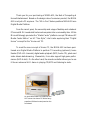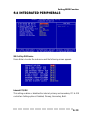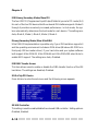
1
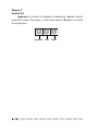
i
FCC-B Radio Frequency Interference Statement
This equipment has been tested and found to comply with the limits for a class B
digital device, pursuant to part 15 of the FCC rules. These limits are designed to
provide reasonable protection against harmful interference when the equipment
is operated in a commercial environment. This equipment generates, uses and
can radiate radio frequency energy and, if not installed and used in accordance
with the instruction manual, may cause harmful interference to radio
communications. Operation of this equipment in a residential area is likely to
cause harmful interference, in which case the user will be required to correct the
interference at his own expense.
Notice 1
The changes or modifications not expressly approved by the party responsible for
compliance could void the user’s authority to operate the equipment.
Notice 2
Shielded interface cables and AC. power cord, if any, must be used in order to
comply with the emission limits.
VOIR LA NOTICE D’INSTALLATION AVANT DE RACCORDER AU RESEAU.
Micro-Star International MEGA 651
Tested to comply
with FCC Standard
For Home or Office Use
ii
Lithium Battery Statement
CAUTION
Danger of explosion if battery is incorrectly replaced. Replace only with the
same or equivalent type recommended by the manufactuer. Discard used batteries according to the manufacturer’s instructions.
Macrovision® Statement
This product incorporates copyright protection technology that is protected by
method claims of certain U.S. patents and other intellectual property rights owned
by Macrovision Corporation and other rights owners. Use of this copyright protection technology must be authorized by Macrovision Corporation, and is intended for home and other limited viewing users only unless otherwise authorized by Macrovision Corporation. Reverse engineering or disassembly is
prohibited.
iii
Safety Instructions
1.
2.
3.
4.
5.
Always read the safety instructions carefully.
Keep this User’s Manual for future reference.
Keep this equipment away from humidity.
Lay this equipment on a reliable flat surface before setting it up.
The openings on the enclosure are for air convection hence protects the
equipment from overheating. DO NOT COVER THE OPENINGS.
6.
Make sure the voltage of the power source and adjust properly 115/230V
before connecting the equipment to the power inlet.
7.
Place the power cord such a way that people can not step on it. Do not
place anything over the power cord.
8.
Always Unplug the Power Cord before inserting any add-on card or module.
9.
All cautions and warnings on the equipment should be noted.
10. Never pour any liquid into the opening that could damage or cause electrical shock.
11. If any of the following situations arises, get the equipment checked by a
service personnel:
- The power cord or plug is damaged.
- Liquid has penetrated into the equipment.
- The equipment has been exposed to moisture.
- The equipment has not work well or you can not get it work according to
User’s Manual.
- The equipment has dropped and damaged.
- The equipment has obvious sign of breakage.
12. DO NOT LEAVE THIS EQUIPMENT IN AN ENVIRONMENT
UNCONDITIONED, STORAGE TEMPERATURE ABOVE 600 C (1400F), IT MAY
DAMAGE THE EQUIPMENT.
CAUTION: Danger of explosion if battery is incorrectly replaced.
Replace only with the same or equivalent type recommended by
the manufacturer.
iv
Copyright Notice
The material in this document is the intellectual property of MICRO-STAR
INTERNATIONAL. We take every care in the preparation of this document, but
no guarantee is given as to the correctness of its contents. Our products are
under continual improvement and we reserve the right to make changes without notice.
Trademarks
All trademarks are the properties of their respective owners.
Intel® and Pentium® are registered trademarks of Intel Corporation.
PS/2 and OS®/2 are registered trademarks of International Business Machines
Corporation.
Windows® 95/98/2000/NT/XP are registered trademarks of Microsoft Corporation.
Netware® is a registered trademark of Novell, Inc.
Award® is a registered trademark of Phoenix Technologies Ltd.
AMI® is a registered trademark of American Megatrends Inc.
Revision History
Revision
V1.0
V1.1
v1.2
v1.3
v1.4
Revision History
First release
Add “Media Center” and “Appendix”
Make update on p. 1-7 & 3-3
Replace v1.0
Special Edition for SI
Remove “Media Center”
Replace v1.1
Update Chapter 3
Replace v1.3
v
Date
April 2003
June 2003
July 2003
July 2003
Sep. 2003
CONTENTS
Introduction
Chapter 1. Getting Started......................................................................1-1
All-in-One Feature Set.......................................................1-2
Front Panel...............................................................1-3
Back Panel.........................................................................1-3
System Specification.....................................................................1-4
Performance PC ............................................................................1-6
Hi-Fi Audio...................................................................................1-8
Home Theater...............................................................................1-10
Chapter 2. Introducing Mainboard...........................................................2-1
Mainboard Layout..........................................................................2-2
CPU/Memory.................................................................................2-3
Introduction to DDR SDRAM................................................2-3
Power Supply.................................................................................2-4
Front Panel...................................................................................2-5
IEEE 1394 Port: J1394-2.......................................................2-5
IEEE 1394 Port: J1394-1........................................................2-6
USB Ports.........................................................................2-6
Mic-in/Head-Phone.............................................................2-7
OPTICAL SPDIF-in..............................................................2-7
Back Panel..................................................................................2-8
Serial Port...........................................................................2-8
VGA Port...........................................................................2-9
Mouse/Keyboard Connectors..............................................2-9
RJ45 LAN Jack..................................................................2-10
USB Ports.............................................................................2-10
OPTICAL SPDIF-out.........................................................2-10
Parallel Port........................................................................2-11
Audio Port..........................................................................2-12
Connectors.................................................................................2-13
vi
IDE Connectors: CN22 & CN23............................................2-13
FDD Connector: CN10.................................................... 2-13
CD-in Connector: CN16......................................................2-14
TV-Tuner Card Connector: CN13...........................................2-14
CPU Fan Connector: CN15.................................................2-14
Front Panel Power Connector: CN4..................................2-15
USB Card Reader Connector: CN6........................................2-15
LCM Connector: CN18.................................................2-16
Modem Module Connector: CN21...........................2-16
Jumper.............................................................................2-17
Clear CMOS Jumper: J2.............................................2-17
Slots......................................................................................2-18
PCI Slot.......................................................................2-18
AGP Slot......................................................................2-18
Chapter 3. Using Audio Function........................................................... 3-1
Introduction.........................................................................3-2
Control Panel..............................................................................3-3
Remote Controller........................................................................3-4
AC Power on................................................................................3-5
Playing CD/MP3 in Hi-Fi Mode.....................................................3-6
Playing FM/AM in Hi-Fi Mode..................................................3-10
Using Audio Function in PC Mode.........................................3-12
Radio Mode.....................................................................3-12
CD\MP Mode......................................................................3-13
Chapter 4: Setting BIOS Function..................................................4-1
Entering Setup..............................................................................4-2
Control Keys..................................................................4-2
Getting Help................................................................4-3
Main Menu........................................................................4-3
Sub-Menu.....................................................................4-3
General Help<F1>............................................................4-3
The Main Menu.............................................................................4-4
vii
Standard CMOS Features.........................................................4-6
Advanced BIOS Features...........................................................4-8
Advanced Chipset Features...........................................................4-11
Integrated Peripherals..............................................................4-13
Power Management Setup.......................................................4-19
PNP/PCI Configurations............................................................4-23
PC Health Status......................................................................4-25
Frequency/Voltage Control...........................................................4-26
Appendix. Using Mega Radio.................................................................A-1
Listening to Radio.........................................................................A-2
Setting Memory Station.................................................................A-6
Recording Music...........................................................................A-7
viii
Introduction
Introducing Y
our
Your
“Digital Media Platform
”
Platform”
Thank you for your purchasing of MEGA 651, the Best of Computing &
Home Entertainment. Based on the design idea of consumer product, the MEGA
651 is not just a PC anymore. The “All-in-One” feature positions MEGA 651 as a
Digital Media Platform.
From the recent years, the ownership and usage of desktop and notebook
PCs across W.W. households has turned computers into a commodity item. While
Microsoft strongly promotes the “Media Center” platform concept “Windows XP
Media Center Edition” on HP “Free Style”, Intel is also exploring their “Digital
Home” concept for the “Home-use” PC.
To meet the new concept of Home PC, the MEGA 651 has been positioned as a Digital Media Platform to perform TV-recording (optional), home
theater (DVD+5.1 channels), digital audio playback (MP3, Audio CD), photo and
video stream data browsing. Meanwhile, it can also support high game performance (AGP 4x slot). On the other hand, the remote controller allows you to use
it like an advanced Hi-Fi stereo in playing CD/MP3 and listening to radio.
An innovative feature to implement the
Hi-Fi stereo into home PC with a fancy
equalizer LCM and control panel on the
front bezel
Introduction
maximize your connection to the digital planet
- Hi-Fi Stereo: Audio CD+MP3 Player+AM/FM Tuner
- Home Theater: DVD + 5.1 Channel + TV Tuner (option)
- Media Center: Card Reader + 1394 + SPDIF I/O +PVR
- Completed PC: Office + Game Machine
A New Digital Media Form Factor from MSI That Allows You to
- Control Live Television
- Enjoy Home Theater (DVD + 5.1 Channel)
- Listen to Digital Music (MP3, Audio CD)
- Burn Music, Photos and Video
- View Your Favorite Photos
- Incredible Gaming Performance
- And more.....
For Home, For Work & For Fun
Getting Started
1
Getting Started
1.1 All-inOne Feature Set
All-in-One
1.2 System Specification
Performance
1.3 P
erformance PC
1.4 Hi-Fi Audio
1.5 Home Theater
○○○○○○○○○○○○○○○○○○○○○○○○○
1-1
Chapter 1
1.1 All-in-one Feature Set
The MEGA651 implements all the Hi-Fi Stereo into Home-PC with a fancy
equalizer LCM and control panel in the front bezel. When PC is power off, you
can use it just like a Hi-Fi Stereo with a remote controller. When PC is power
on, you can use it for Home Theater and Media Center PC. The all-in-one feature
provides you with multiple functions in a small form factor. It can be set anywhere you want, such as bedroom or living room, while it’s easily be moved to
anywhere whenever you need.
See the following for the feature:
TV-out(option)
TV-Tuner (Option)
5.1 Channel
Hi-Fi Power Switch
Optical Drive (Option)
Equalizer LCM
PC Power Switch
Card Reader (Standard)
FDD/2nd HDD (Option)
MDC Modem
Remote Controller
-
Hi-Fi Stereo: Audio CD+ MP3 Player+ AM/FM Tuner (power off)
-
Home Theater: DVD+ 5.1 Channel
Media Center: A/V Browsing/Radio Turning (Card Reader+
1394+ SPDIF I/O+CD-RW) + PVR (TV Tuner)
Completed PC: Office+ Game Machine
-
1-2
○○○○○○○○○○○○○○○○○○○○○○○○○
Getting Started
Front Panel
Hi-Fi Power Switch
IR Receiver
Mode
Eject/Stop
Forward
Play/Pause
Backward
Shuttle Controller
PC Power Switch
HDD LED
PC Reset
Optical SPDIF-in
Mic-in
J1394-2
USB x 2
J1394-1
Head-Phone
Back Panel
Mouse
Power Jack
LAN Port
Parallel Port
Radio Antenna
Jack
Serial Port
Modem
Lin-in
Keyboard
USB x 2 Speak-out
PCI Slot
VGA Port
AGP Slot
Optical SPDIF-out
Mic-in
○○○○○○○○○○○○○○○○○○○○○○○○○
1-3
Chapter 1
1.2 System Specification
M/B
- MS-6760 (Proprietary F/F), 185 x 290 mm (4 layer)
CPU:
- Support Socket 478 for Pentium® 4, 2.8 GHz
Chipset:
- SiS 651 + SiS 962
Memory:
- DDR 333 x 2, support memory up to 2.0GB
On-Board Audio:
- AC’97 Codec integrated in ALC 650, support 5.1 channel , SPDIF In/Out.
On-Board VGA:
- Integrated (AGP 4X)
** On-Board VGA memory: None
On-Board Communication
- LAN: integrated in Realtek (10/100Mb)
- Modem: 56K MDC module
On-Board USB
- Front x 2; Rear x 2; On-Board x 2 for Card Reader & RF K/B, M/S (MFG Option)
On-Board IEEE 1394:
- RTL8801B PHY (2 ports), Front x 2 (4 pin, 6 pin)
Expansion Slots:
- PCI 2.2 x 1, AGP (4X) x1
Power Off Function:
- Playback Audio CD, MP3, AM/FM Radio Tuner (with Remote Controller)
TV Tuner Function
- MS-8606 (Option PCI with remote controller)
Power Supply:
- 200W (PFC 5V/12V SB) Full Range
Chassis:
- 202(W) x 320(D) x 151(H) mm (9.76 Liters)
1-4
○○○○○○○○○○○○○○○○○○○○○○○○○
Getting Started
On-Board Headers & Connectors
- Rear Panel: Parallel Port x 1, Serial Port x 1, VGA x 1, PS/2 x 2, Mic in/Line in/
Line out x 1, USB x 2, LAN (RJ45) x 1, SPDIF/O x 1, Modem (RJ11) x 1
- Front Panel: Mic in/Headphone x 1, USB x 2, SPDIF/I x 1, 1394 x 1 (4-pin), 1394
x 1(6-pin)
BIOS
- 2MB Flash
Others
- Microsoft® PC 2001
- LAN Wake Up Function
- Suspend to RAM/DISk function
- Top Tech III (Thermal Overheat Protection Technology)
- PC Alert System Hardware Monitor
- On-Board BlueBird Module for Power-Off features
- On-Board Equalizer (LCM)
○○○○○○○○○○○○○○○○○○○○○○○○○
1-5
Chapter 1
1.3 Performance PC
When PC is power on, the MEGA651 is your performance PC. Power on
means “If the power button of PC is pressed, the Hi-Fi stereo has no function even
you press the Hi-Fi button.”
Press the Power button to start
the PC function
Features
CPU support: Intel P4
PCI/AGP Expansion
Front I/O
- Mic-in/Head-Phone
- USB x 2
- 1394 x 2 (6-pin & 4-pin)
- Optical SPDIF-in
- 6-in-1 Card Reader
Rear I/O
- COM/VGA/Parallel/PS2 x 2
- LAN (RJ45)
- USB x 2
- Optical SPDIF-out
- Speaker-out/Line-in/Mic-in (5.
1channel)
- Modem
- Radio Antenna
See Chapter 2 for more information of mainboard, Front and Rear I/O.
1-6
○○○○○○○○○○○○○○○○○○○○○○○○○
Getting Started
Target Operating System
-- Microsoft Windows XP Home Edition
Security
-- The security features protect the data of machine from unveiled publicity and
unauthorized access through BIOS control.
Password
-- The MEGA651 uses two levels of BIOS access (User Password & Supervisor
Password) to protect the computer system.
Storage Subsystem
1) Floppy (Standard Floppy & USB Floppy)
2) Hard Disk
3) CD-ROM (OPTIONAL)
4) DVD-ROM (OPTIONAL)
5) CD-RW (OPTIONAL)
6) DVD/CD-RW Combo (OPTIONAL)
In pure barebone Hi-Fi mode with NO CPU, Memory, Had
Disk intalled, if you push the PC power button, the system
will deadly hang up. The Hi-Fi mode will be malfunction.
It’s impossible to recover the system by pressing power
button for 4 seconds. The only way is to unplug power
cord and reset the system.
○○○○○○○○○○○○○○○○○○○○○○○○○
1-7
Chapter 1
1.4 Hi-Fi Audio
When PC is power off, the MEGA651 can be used as a Hi-Fi audio. You
can press the Hi-Fi button or use the remote controller to start the audio function.
Power-off means “When used as a Hi-Fi audio, the PC should be in power-off
status. If you press the PC power button on, the Hi-Fi audio will be disabled .”
Option 1
Press the Power button to use the
audio function
Option 2
Press the Hi-Fi button to use the
audio function
Features
LCM Display, Clock, AM/FM Radio Tuner, Audio CD Play,
MP3 CD Play, SRS
See Chapter 3 for more information of using audio function.
1-8
○○○○○○○○○○○○○○○○○○○○○○○○○
Getting Started
SRS
MEGA651 is equipped with SRS audio enforcement technology. SRS (Sound Retrieval System) was
the first generation of 3D sound, dramatically improving the quality of standard stereo. SRS is based on the
human hearing system and was designed to retrieve
the natural spatial cues and ambient information that
is present in audio but masked by traditional recording and playback methods.
Whether the signal is mono or stereo, SRS expands the audio material to create a realistic threedimensional sound image. SRS has no sweet-spot and
fills the room with a sound experience much closer to
that of a live performance.
SRS is a trademark of SRS Labs, Inc. SRS technology is incorporated under license from SRS Labs,
Inc.
○○○○○○○○○○○○○○○○○○○○○○○○○
1-9
Chapter 1
1.5 Home Theater
Except the general PC function, the MEGA651 has the extra Home Theater function when PC button is pressed on.
When PC button is pressed on, you can use the equipped optical drive to
play DVD. The equipped 5.1 channel audio effect gives you a wonderful feeling
of home theater while playing DVD.
Plus, the OPTIONAL MS-8606 TV-Tuner card allows you to watch TV.
The top part of remote controller is designed specially for the TV-Tuner function.
For more informaiton on MS-8606 TV Tuner card, please refer to the maual
packed in MS-8606. After inserting the TV Tuner card, remember to install the
driver packed in CD to using the function.
1-10
○○○○○○○○○○○○○○○○○○○○○○○○○
Introducing Mainboard
2
Introducing Mainboard
2.1 Mainboard Layout
2.2 CPU/Memory
Power
2.3 P
ower Supply
anel
2.4 Front P
Panel
Panel
anel
2.5 Back P
2.6 Connectors
2.7 Jumper
2.8 Slots
○○○○○○○○○○○○○○○○○○○○○○○○○
2-1
Chapter 2
2.1 Mainboard layout
CN1
AUDIO1
FDD Connector
J1
AUDIO 2
USB2
USB1
J 1394-2
J 1394-1
The MEGA651 is equipped with MS6760 proprietary mainboard.
See the following for the mainboard layout:
IDE Connectors
CN6
USB Card Reader Connector
CN10
Radio Module
CN1
SiS962
CN5
CN8
SM
BluebirdVL+
CN23
DDR DIMM Slots
CN12
CN22
Front Panel Connector
CN26
Clear CMOS Jumper
C8
BATT
+
CN28
Radio Antenna Connector
LCM Connector
Front Panel Power
Connector
AGP Slot
J2
SiS651
Winbond
W83697HF
BIOS
Realtek
RTL8801B
CN4
USB Connector
PCI Slot 1
AGP Slot
Bottom:
SPDIF
Line_Out
Line_In
Mic
PCI Slot
Codec
TV Audio Connector
CN7
CN13
CN16
CN21
Top :
Parallel Port
Top: LAN Jack
Bottom: USB
ports
Top : mouse
Bottom: keyboard
Power Supply Connector
Top : COM1
Bottom: VG A Port
CN20
Realtek
RTL8101L
Modem Module Connector
ATX
Power Supply
CN15
CPU Fan Connector
ATX Power Supply
CD-IN Connector
Hi-Fi Power Connector
MS6760 v1.X Mainboard
2-2
○○○○○○○○○○○○○○○○○○○○○○○○○
Introducing Mainboard
2.2 CPU/memory
The MEGA651 supports Intel® Pentium® 4 processors in the 478-pin
package. The mainboard uses a CPU socket called PGA478 for easy CPU
installation. When you are installing the CPU, make sure the CPU has a heat sink
and a cooling fan attached on the top to prevent overheating.
Overheating
Overheating will seriously damage the CPU and system,
always make sure the cooling fan can work properly to
protect the CPU from overheating.
The mainboard provides 2 slots for 184-pin DDR SDRAM DIMM (Double
In-Line Memory Module) modules and supports the memory size up to 2GB. You
can install PC2700/DDR333 or PC2100/DDR266 modules into the DDR DIMM
slots (CN28/26).
Introduction to DDR SDRAM
CN26
CN28
DDR (Double Data Rate) SDRAM is
similar to conventional SDRAM, but
doubles the rate by transferring data twice
per cycle. It uses 2.5 volts as opposed to 3.
3 volts used in SDR SDRAM, and requires
184-pin DIMM modules rather than 168pin DIMM modules used by SDR SDRAM.
High memory bandwidth makes DDR an
ideal solution for high performance PC,
workstations and servers.
○○○○○○○○○○○○○○○○○○○○○○○○○
2-3
Chapter 2
2.3 Power Supply
The system is equipped with a 200W(PFC) ATX power supply. The power
cord of power supply has been connected to the connectors on the mainboard
when shipped out. You can find two connectors (20-Piin & CN 20) on the
mainboard.
ATX Power Supply Pin Definition
PIN
SINGAL
PIN
SIGNAL
1
2
3
4
5
6
7
8
9
3.3V
3.3V
GND
5V
GND
5V
GND
PW_OK
5V_SB
3.3V
-12V
GND
PS_ON
GND
GND
GND
10
12V
11
12
13
14
15
16
17
18
19
20
10
20
1
11
20-Pin
Connector
5V
5V
CN20 Pin Definition
PIN
SINGAL
3
4
1
2
3
4
GND
GND
12V
12V
1
2
CN 20
Power Supply Specification
Dimension
70 (H)x1450(W)x105(D) mm
PFC
Yes (passive)
Wattage
200W Max
Electrical Design Specification
AC Output :100-127/200-240 VAC, Switch
Selectable, Auto Protection
DC Output :+3.3V 17A
:+5V 12A
:+12V 13.5A
:-12V 0.5A
:+5Vsb 3A
:+12Vsb 2.5A
80 mm PWM Fan
Certificate
2-4
FCC/UL/CUL/BSMI/CB/NEMKO/TUV
○○○○○○○○○○○○○○○○○○○○○○○○○
Introducing Mainboard
2.4 Front panel
The Front Panel is independent and extended from the mainboard. It’s
connected to the Front Panel Connector on the mainboard. You can find the
following ports on the Front Panel.
Optical SPDIF-In
Mic-In
USB x 2
J1394-1
J1394-2
Head-Phone
IEEE 1394 Port: J1394-2
The mainboard provides two IEEE 1394 ports. This smaller one is designed for you to connect the IEEE 1394 device with external power. The IEEE
1394 high-speed serial bus complements USB by providing enhanced PC connectivity for a wide range of devices, including consumer electronics audio/video
(A/V) appliances, storage peripherals, other PCs, and portable devices.
Software Support
IEEE 1394 Driver is provided by Windows® 98 SE, Windows® XP, Windows® ME and Windows® 2000. Just plug in
the IEEE 1394 connector into the port. These Operating Systems will install the driver for IEEE 1394.
○○○○○○○○○○○○○○○○○○○○○○○○○
2-5
Chapter 2
IEEE 1394 Port: J1394-1
The bigger 6-pin IEEE 1394 Port on the back panel is designed for you to
connect to IEEE 1394 devices without external power. That means the mainboard
can provide the power for the devices connected to this port.
Software Support
IEEE 1394 Driver is provided by Windows® 98 SE, Windows® XP, Windows® ME and Windows® 2000. Just plug in
the IEEE 1394 connector into the port. These Operating Systems will install the driver for IEEE 1394.
USB Ports
The mainboard provides an OHCI (Universal Host Controller Interface)
Universal Serial Bus root for attaching USB devices such as keyboard, mouse or
other USB-compatible devices. You can plug the USB device directly into the
connector.
USB Port Description
PIN
1
2
3
4
5
6
7
8
2-6
SIGNAL
VCC
-Data 0
+Data 0
GND
VCC
-Data 1
+Data 1
GND
DESCRIPTION
+5V
Negative Data Channel 0
Positive Data Channel 0
Ground
+5V
Negative Data Channel 1
Positive Data Channel 1
Ground
○○○○○○○○○○○○○○○○○○○○○○○○○
Introducing Mainboard
Mic-in/Head-Phone
Mic-in is a connector for microphone. Head-Phone is a connector for
Speakers or Headphones.
OPTICAL SPDIF-in
The OPTICAL connector allows you to receive the audio file of SPDIF
interface for recording and playing.
The SPDIF (Sony & Philips Digital Interface) is developed jointly by the
Sony and Philips corporations . A standard audio file transfer format, SPDIF
allows the transfer of digital audio signals from one device to another without
having to be converted first to an analog format.
○○○○○○○○○○○○○○○○○○○○○○○○○
2-7
Chapter 2
2.5 Back panel
The Back Panel provides the following ports:
Serial Port
Mouse
VGA Port
LAN Port
Keyboard USB x 2
Parallel Port
Optical SPDIF-out Lin-in Mic-in
Speak-out
Serial Port
The mainboard offers a 9-pin male DIN serial port . The port is 16550A
high speed communication ports that sends/receives 16 bytes FIFOs. You can
attach a serial mouse or other serial devices directly to the connector.
1
2
6
3
7
4
8
9
9-Pin Male DIN Connector
2-8
Pin Definition
5
PIN
SIGNAL
DESCRIPTION
1
2
3
4
5
6
7
8
9
DCD
SIN
SOUT
DTR
GND
DSR
RTS
CTS
RI
Data Carry Detect
Serial In or Receive Data
Serial Out or Transmit Data
Data Terminal Ready
Ground
Data Set Ready
Request To Send
Clear To Send
Ring Indicate
○○○○○○○○○○○○○○○○○○○○○○○○○
Introducing Mainboard
VGA Port
The mainboard provides one DB 15-pin female connector to connect a
VGA monitor.
Pin Definition
5
1
15
Analog Video Display Connector (DB-15s)
11
DB 15-Pin Female Connector
PIN
SIGNAL DESCRIPTION
1
2
3
4
5
6
7
8
9
10
11
12
13
14
15
Red
Green
Blue
Not used
Ground
Ground
Ground
Ground
Power
Ground
Not used
SDA
Horizontal Sync
Vertical Sync
SCL
Mouse/Keyboard Connectors
The mainboard provides two standard mini DIN connectors for attaching
PS/2 mouse and keyboard. You can plug a PS/2® mouse or keyboard directly
into the connector.
®
Pin Definition
6
5
3
4
1
2
PS/2 Mouse (6-pin Female)
PIN
SIGNAL
DESCRIPTION
1
2
3
4
5
6
Mouse DATA
NC
GND
VCC
Mouse Clock
NC
Mouse DATA
No connection
Ground
+5V
Mouse clock
No connection
PIN
1
2
3
4
5
6
SIGNAL
Keyboard DATA
NC
GND
VCC
Keyboard Clock
NC
Pin Definition
6
5
3
4
2
1
PS/2 Keyboard (6-pin Female)
DESCRIPTION
Keyboard DATA
No connection
Ground
+5V
Keyboard clock
No connection
○○○○○○○○○○○○○○○○○○○○○○○○○
2-9
Chapter 2
RJ45 LAN Jack
The mainboard provides one standard RJ-45 jack for connection to Local
Area Network (LAN). You can connect a network cable to the LAN jack.
Pin Definition
PIN
SIGNAL
1
TDP
DESCRIPTION
Transmit Differential Pair
2
TDN
Transmit Differential Pair
3
RDP
Receive Differential Pair
4
NC
Not Used
5
NC
Not Used
6
RDN
Receive Differential Pair
7
NC
Not Used
8
NC
Not Used
USB Ports
The mainboard provides an OHCI (Universal Host Controller Interface)
Universal Serial Bus root for attaching USB devices such as keyboard, mouse or
other USB-compatible devices. You can plug the USB device directly into the
connector.
USB Port Description
1
2
3
4
5
6
7
8
USB Ports
PIN
1
2
3
4
5
6
7
8
SIGNAL
VCC
-Data 0
+Data 0
GND
VCC
-Data 1
+Data 1
GND
DESCRIPTION
+5V
Negative Data Channel 0
Positive Data Channel 0
Ground
+5V
Negative Data Channel 1
Positive Data Channel 1
Ground
OPTICAL SPDIF-out
The OPTICAL connector allows you to play the audio file of SPDIF interface.
See p. 2-7 for more information.
2-10
○○○○○○○○○○○○○○○○○○○○○○○○○
Introducing Mainboard
Parallel Port
The mainboard provides a 25-pin female centronic connector as LPT. A
parallel port is a standard printer port that supports Enhanced Parallel Port (EPP)
and Extended Capabilities Parallel Port (ECP) mode.
13
1
14
25
Pin Definition
PIN
SIGNAL
DESCRIPTION
1
2
3
4
5
6
7
8
9
10
11
12
13
14
15
16
17
18
19
20
21
22
23
24
25
STROBE
DATA0 Data0
DATA1
DATA2
DATA3
DATA4
DATA5
DATA6
DATA7
ACK#
BUSY
PE
SELECT
AUTO FEED#
ERR#
INIT#
SLIN#
GND
GND
GND
GND
GND
GND
GND
GND
Strobe
Data1
Data2
Data3
Data4
Data5
Data6
Data7
Acknowledge
Busy
Paper End
Select
Automatic Feed
Error
Initialize Printer
Select In
Ground
Ground
Ground
Ground
Ground
Ground
Ground
Ground
○○○○○○○○○○○○○○○○○○○○○○○○○
2-11
Chapter 2
Audio Port
Speak-out is a connector for Speakers or Headphones. Line In is used for
external CD player, Tape player, or other audio devices. Mic-in is a connector
for microphones.
Speak-out
2-12
Lin-in
Mic-in
○○○○○○○○○○○○○○○○○○○○○○○○○
Introducing Mainboard
2.6 Connectors
IDE Connectors: CN22 & CN23
The mainboard has a 32-bit Enhanced PCI IDE and Ultra DMA 33/66/100
controller that provides PIO mode 0~4, Bus Master, and Ultra DMA/33/66/100
function. The two connectors on the mainboard allows you to connect to two
IDE device.
CN22 (Primary IDE Connector)
- CN22 can only connect a HDD.
CN23 (Secondary IDE Connector)
- CN23 can only connect a CD-ROM drive.
CN22
CN23
If you install two hard disks on cable, you must configure the second drive to Slave mode by setting its jumper.
Refer to the hard disk documentation supplied by hard
disk vendors for jumper setting instructions.
FDD Connector: CN10
The mainboard provides you with a standard floppy disk drive connector
that supports 1.44M floppy disk type.
CN10
○○○○○○○○○○○○○○○○○○○○○○○○○
2-13
Chapter 2
CD-in Connector: CN16
The connector is for CD-ROM audio connector.
JCD1
L GND R
CN16
TV-Tuner Card Connector: CN13
The mainboard provides the connector to connect the TV-Tuner card.
The TV-Tuner card is included in the package. You can insert the TV-Tuner card
into the PCI Slot 1.
L GND R
CN13
CPU Fan Connector: CN15
The CPU Fan connector supports system cooling fans with +12V that is
controlled by PWM. When connecting the wire to the three-pin head connectors,
always note that the red wire is the positive and should be connected to the +12V
(that is controlled by PWM), the black wire is Ground and should be connected
to GND.
CN15
GND
+12V
SENSOR
2-14
○○○○○○○○○○○○○○○○○○○○○○○○○
Introducing Mainboard
Front Panel Power Connector: CN4
The mainboard provides a Front Panel connector for electrical connection
to the Front Panel switches and LEDs. CN4 is compliant with Intel® Front Panel
I/O Connectivity Design Guide.
1
2
HDD
LED
Power LED
Reset
Switch
Power
Switch
9
10
CN4
CN4 Pin Definition
PIN
SIGNAL
DESCRIPTION
1
2
3
4
5
6
7
8
9
HD_LED_P
FP PWR/SLP
HD_LED_N
FP PWR/SLP
RST_SW_N
PWR_SW_P
RST_SW_P
PWR_SW_N
RSVD_DNU
Hard disk LED pull-up
MSG LED pull-up
Hard disk active LED
MSG LED pull-up
Reset Switch low reference pull-down to GND
Power Switch high reference pull-up
Reset Switch high reference pull-up
Power Switch low reference pull-down to GND
Reserved. Do not use.
USB Card Reader Connector: CN6
The mainboard provides a connector to connect the USB Card Reader on
the Front Panel.
○○○○○○○○○○○○○○○○○○○○○○○○○
2-15
Chapter 2
LCM Connector: CN8
The connector is used to connect the LCM on the front panel.
CN 8
VCC3SBY
+12VSBY
2
1
SPI Bus
Key (0-~5)
GND
CD_SMI
VCC5
HDLED
GND
PWRBTNH
IR
FP_RST
GND
GND
LED-BL
VCC5SBY
26
25
Modem Module Connector: CN21
The mainboard provides the connector to connect the modem module.
The modem module is directly inserted into the connector without an extra cable.
2-16
○○○○○○○○○○○○○○○○○○○○○○○○○
Introducing Mainboard
2.7 Jumper
There is a CMOS RAM on board that has a power supply from external
battery to keep the data of system configuration. With the CMOS RAM, the system can automatically boot OS every time it is turned on. That battery has long
life time for at least 5 years. If you want to clear the system configuration, use the
JBAT1 (Clear CMOS Jumper ) to clear data. Follow the instructions below to clear
the data:
Clear CMOS Jumper: J2
1
1
3
3
Keep Data
Clear Data
You can clear CMOS by shorting 2-3 pin while the
system is off. Then return to 1-2 pin position. Avoid
clearing the CMOS while the system is on; it will damage the mainboard.
○○○○○○○○○○○○○○○○○○○○○○○○○
2-17
Chapter 2
2.8 Slots
PCI Slot
The PCI slot allows you to insert PCI card or TV Tuner
card. The TV Tuner card is included in the MEGA651.
When adding or removing expansion cards, make sure
that you unplug the power supply first. Meanwhile, read the
documentation for the expansion card to make any necessary hardware or software settings
NOTE: You can insert the OPTIONAL MS8606 card into the
PCI slot to enjoy watching TV.
PCI Slot 1
AGP (Accelerated Graphics Port) Slot
The AGP slot allows you to insert the AGP graphics
card. AGP is an interface specification designed for the
throughput demands of 3D graphics. It introduces a 66MHz,
32-bit channel for the graphics controller to directly access
main memory and provides three levels of throughputs: 1x
(266Mbps), 2x (533Mbps) and 4x (1.07Gbps).
AGP Slot
2-18
○○○○○○○○○○○○○○○○○○○○○○○○○
Using Audio Function
3
Using Audio Function
3.1 Control Panel
3.2 Remote Controller
3.3 AC Power on
3.4 Playing CD/MP3 in Hi-Fi Mode
3.5 Playing FM/AM in Hi-Fi Mode
3.6 Using Audio Function in PC Mode
○○○○○○○○○○○○○○○○○○○○○○○○○○
3-1
Chapter 3
Introduction
The MEGA 651 is featured with audio function. There are
two ways to use audio function: in PC mode, in Hi-Fi mode. As
the Mega 651 is shipped out in barebone, you must install the
necessary components (such as HDD, CPU, RAM...) before using audio function in PC mode. However, there is no limit to
use audio function in Hi-Fi mode, although the system is not set
up completely.
You can use control panel or remote controller to select
the audio function in Hi-Fi mode. However, you can also use
the control panel or remote control to select the audio function
in PC mode. See 3.1 and 3.2 for information on control panel
and remote controller. On the other hand, the “Mega Radio”
software has been included in package which allows you to
listen to the radio in PC mode. See Appendix for information on
“Mega Radio”.
In this chapter, we will tell you how to use audio function
in Hi-Fi and PC mode. The LCM pictures are used to provide the
information step by step.
3-2
○○○○○○○○○○○○○○○○○○○○○○○○○
Using Audio Function
3.1 Control Panel
Hi-Fi Power Switch
IR Receiver
Mode
Eject/Stop
Forward
Play/Pause
Backward
Shuttle Controller
HiFi Power Start the audio function.
Mode
Choose the audio mode (CD/MP3, FM, AM)
Eject/Stop
Eject the CD/MP3 or stop the play. In Hi-Fi
mode, you can press this button to recall memory
sub-mode.
Forward
Forward the channel search in FM/AM mode or
forward the music selection in MP3 mode.
Play/Pause Play or pause the play in CD/MP3, AM, FM modes.
In Hi-Fi mode, you can press this button to store
the memory station.
Backward
Shuttle
Backward the channel search in FM/AM mode or
backward the music selection in CD/MP3 mode.
a. Adjust volume b. Set EQ/Play mode
c. Set SRS and timer
○○○○○○○○○○○○○○○○○○○○○○○○○○
3-3
Chapter 3
3.2 remote Controller
The buttons on the bottom are used for audio function while the ones on
the top are used for TV application. See the manual of TV Tuner Card MS8606
for information on top part button.
Function Keys for TV
application
SRS on/off Button
Control Buttons
Mute Button
Mode Button
(CD/MP3/FM/AM)
EQ Mode Button
Hi-Fi Power
Adjusting Volume
Play Mode Button
Control Buttons These buttons allow you to eject/stop, forward, play/pause and backward
the play in CD, MP3, AM or FM mode. See p. 3-3 for detail desciption.
Mute Button
Press this button to mute the volume.
Hi-Fi Power
Press this button to use the function of Hi-Fi audio.
Mode Button
There are three buttons:CD/MP3, FM and AM. Choose the mode you want.
Adjusting
Volume
Use this button to adjust the volume.
EQ Mode
Use this button to set EQ sub-mode (Normal, POP, Classic, Jazz) in playing
CD. See p. 3-9 for more information.
Play Mode
Use this button to set play sub-mode (Normal, Random, Repeat Disc) in
playing CD. See p. 3-8 for more information.
3-4
○○○○○○○○○○○○○○○○○○○○○○○○○
Using Audio Function
3.3 AC Power ON
- Plug in the power cord
Plug in the power cord. You will see
the panel (LCM) items FLASH 2 times.
- Set Timer
Then you can adjust time by shuttle. You
will see timer 00:00 flash.
Turn the shuttle clockwise to adjust
minute.
Turn the shuttle counterclockwise to
adjust hour. After adjusting the minute
and hour, press the shuttle to set the
timer. The second will be reset to zero
while setting the timer.
○○○○○○○○○○○○○○○○○○○○○○○○○○
3-5
Chapter 3
3.4 playing CD/Mp3 in Hi-fi mode
- Select CD/MP3
Press HiFi button to start the audio
function. Press MODE on the Control
Panel to select CD/MP3 mode or press
CD/MP3 on the remote controller to
play CD/MP3.
If there is no CD in the tray or CD is
broken, the LCM shows “NO disc”.
Press the Eject/Stop button to open the
disc tray and put CD/MP3 in.
If the disc in the tray is CD, the LCM
shows CD. If the disc in the tray is MP3,
the LCM shows MP3.
- Play music
Press the “Forward” button to play the
music. The icon
will run a circle.
The LCM shows
.
1 means the first song. 00 means minute.
02 means second.
3-6
○○○○○○○○○○○○○○○○○○○○○○○○○
Using Audio Function
- Pause Music
Press “Play/Pause” button to pause the
music. The LCM shows
.
- Play Next Song
Press the “Forward” button to play the
next song. There is no action if you
hold “Forward” button.
- Replay the song
Press “Backward” button once to replay the song.
- Replay previous song
Press the “Backward” button twice (in
2 seconds) to play the previous song
(After 2 seconds, it replay the song).
- Eject/Stop
Press the “Eject/Stop” button once to
stop the music or open the CD-ROM.
Press “Forward” button to play the song
after rejecting.
○○○○○○○○○○○○○○○○○○○○○○○○○○
3-7
Chapter 3
- Adjusting volume
Turn the shuttle clockwise to turn the
volume up and counterclockwise to
turn the volume down.
- Set Play Sub-Mode
Press the shuttle once to set the Play
Sub-Mode (NORMAL, RANDOM,
REPEAT, and REPEAT DISC)
: :Allows you to play the CD in normal
Turn the shuttle to choose Play SubMode. The item you choose will flash
selection.
and the others are on. Wait for 5 seconds to set the Play Sub-Mode and go
selection.
:Allows the system makes the random
back to volume mode. You can also
press the shuttle to set it and change
:Allows you to repeat the song.
to the EQ Sub-Mode at the same time.
:Allows you to repeat the whole disc.
NOTE: You can also press the “PLAY MODE”
button on the remote controller to set the SubMode.
Press the shuttle twice (if you want to
skip the Play Sub-Mode) to set the EQ
Sub-Mode (NORMAL, POP, CLASSIC,
JAZZ).
3-8
○○○○○○○○○○○○○○○○○○○○○○○○○
Using Audio Function
: To play the CD/MP3 in Normal mode.
- Set EQ Sub-Mode
Turn the shuttle to choose EQ SubMode. The item you choose will flash
and the others are on. Wait for 5 sec-
: To play the CD/MP3 in Classic mode.
onds to set the EQ Sub-Mode and go
back to volume mode. You can also
: To play the CD/MP3 in Jazz mode.
press the shuttle to set it and change
to the Timer Sub-Mode at the same
: To play the CD/MP3 in POP mode.
time.
NOTE: You can also press the “EQ MODE” button
on the remote controller to set it.
Press the shuttle thrice (if you want to
skip Play and EQ sub-modes) to set the
Timer sub-mode. The operation of setting is the same as AC power on. After
that, it changes to the Volume submode. The LCM shows
.
- Turn on SRS
Press the shuttle four times to turn on
SRS. You can also press the MTS button on the remote controller to turn on
SRS.
○○○○○○○○○○○○○○○○○○○○○○○○○○
3-9
Chapter 3
3.5 playing FM/AM in Hi-fi mode
- Select AM/FM
Press the “MODE” button on the Control Panel to set AM/FM mode or press
AM/FM button on the Remote Controller to switch to AM or FM station.
- Next Available Station
Press the “Forward” button to jump to
the next available station.
- Previous Available Station
Press the “Backward” button to jump to
the previous available station.
- Memory Station
Press the “mem.set (Play/Pause)” button to store the memory station and
turn the shuttle to choose the spot you
want to save. Press the shuttle to set it
(You can set up to 6 spots. You will see
“
“ on the LCM.)
3-10
○○○○○○○○○○○○○○○○○○○○○○○○○
Using Audio Function
- Adjusting Volume
Turn the shuttle to adjust the volume.
- Recall Memory Station
Press the “Eject/Stop” once to recall the
memory sub-mode and turn the shuttle
to choose the number of spot (1-6) to
play.
- Set EQ Sub-Mode
Press the shuttle once into the “EQ”
sub-mode. Turn the shuttle to choose
the sub-mode. The operation is the
same as in CD/MP3 mode.
- Set Timer
Press the shuttle twice to set the Timer
sub-mode (operation is the same as in
AC power on). After you set the hour
and minute, it changes to the volume
sub-mode. The LCM shows
.
NOTE: Press the shuttle thrice or press
the MTS button on the remote controller
to turn the SRS on.
○○○○○○○○○○○○○○○○○○○○○○○○○○
3-11
Chapter 3
3.6 Using audio function in PC mode
Radio Mode
You can use Remote Controller or Front Panel to control the audio function.
Basically, the operation is very similar to that in Hi-Fi mode. The difference is
in memory station setting.
Remote Controller Function
1. Press “Hi-Fi” button to turn on/off radio.
2. Press “FM/AM” button to launch MSI Mega Radio to listen to radio.
3. Press “Mute” button to mute the volume.
4. Press “Vol up/down” button to adjust volume.
5. Press “Forward/Backward” button to get an available station.
<Setting Memory Station>
a. Get an available station.
b. Press “mem.set”.
c. Use “Forward/Backward” button to choose the station number
you want to store.
d. Press “mem.set” again.
<Calling Memory Station>
a. Press “Memory”.
b. Use “Forward/Backward” button to choose the memory station.
<Reset Memory Station>
a. Use “Forward/Backward” button to choose the NEW station
number.
b. Press “mem.set” to reset the station.
3-12
○○○○○○○○○○○○○○○○○○○○○○○○○
Using Audio Function
Front Panel Function
1. Press “Hi-Fi” button to turn on/off radio.
2. Press “Mode” button to launch MSI Radio to listen to radio.
3. Turn “Shuttle” to adjust the volume.
4. Press “Forward/Backward” button to get an available station.
Memory Station
The shuttle is not allowed to set the memory station as
in Hi-Fi mode. Use the “mem.set” button on the remote
controller to set the memory station.
CD/MP3 Mode
To listen to the play of CD/MP3 in PC mode, you must use the application
“Media Player” that is equipped in Windows. As in Radio Mode, there are two
ways (Remote Controller/Front Panel) to use the CD/MP3 audio function.
Before playing MP3 in PC mode, you need to download the
MP3 file into system, and then add the file to the playlist.
The Mega 651 is not allowed to play music automatically
after inserting MP3
○○○○○○○○○○○○○○○○○○○○○○○○○○
3-13
Chapter 3
Remote Controller Function
1. Press “Hi-Fi” button to turn on/off CD/MP3.
2. Press “FM/AM/CDMP3” button to select the mode you want.
3. Press “Mute” button to mute the volume.
4. Press “Vol up/down” button to adjust volume.
5. Press “Forward/Backward” button to get the next/last song.
6. Press “Play/Pause” button to play/pause the song.
7. Press “Eject” button to eject/retrieve the tray.
Memory Station
The “Eject” button is not allowed to recall the memory
station as in Hi-Fi mode. It can only be used to eject or
retrieve the tray.
Front Panel Function
1. Press “Hi-Fi” button to turn on/off CD/MP3.
2. Press “FM/AM/CDMP3” button to select the mode you want.
3. Turn “Shuttle” to adjust the volume.
4. Press “Forward/Backward” button to get an available station.
6. Press “Play/Pause” button to play/pause the song.
7. Press “Eject” button to eject/retrieve the tray.
Memory Station
The “Eject” button is not allowed to recall the memory
station as in Hi-Fi mode. It can only be used to eject or
retrieve the tray.
3-14
○○○○○○○○○○○○○○○○○○○○○○○○○
Setting BIOS Function
4
Setting BIOS Function
4.1 Entering Setup
4.2 The Main Menu
4.3 Standard CMOS Features
4.4 Advanced BIOS Features
4.5 Advanced Chipset Features
eripherals
4.6 Integrated P
Peripherals
ower Management Setup
Power
4.7 P
4.8 PnP/PCI Configurations
4.9 PC Health Status
4.10 Frequency/V
oltage Control
Frequency/Voltage
○○○○○○○○○○○○○○○○○○○○○○○○○
4-1
Chapter 4
4.1 Entering Setup
Power on the computer and the system will start POST (Power On Self
Test) process. When the message below appears on the screen, press <DEL> key
to enter Setup.
Press DEL to enter SETUP
If the message disappears before you respond and you still wish to enter
Setup, restart the system by turning it OFF and On or pressing the RESET button.
You may also restart the system by simultaneously pressing <Ctrl>, <Alt>, and
<Delete> keys.
Control Keys
<↑>
Move to the previous item
<↓>
Move to the next item
<←>
Move to the item in the left hand
<→>
Move to the item in the right hand
<Enter>
Select the item
<Esc>
Jumps to the Exit menu or returns to the main menu from a submenu
<+/PU>
Increase the numeric value or make changes
<-/PD>
Decrease the numeric value or make changes
<F1>
General help, only for Status Page Setup Menu and Option Page
<F5>
Restore the previous CMOS value from CMOS, only for Option Page
Setup Menu
Setup Menu
<F6>
Load the default CMOS value from Fail-Safe default table, only for
Option Page Setup Menu
4-2
<F7>
Load Optimized defaults
<F10>
Save all the CMOS changes and exit
○○○○○○○○○○○○○○○○○○○○○○○○○
Setting BIOS Function
Getting Help
After entering the Setup menu, the first menu you will see is the Main
Menu.
Main Menu
The main menu lists the setup functions you can make changes to. You
can use the control keys ( ↑↓ ) to select the item. The on-line description of the
highlighted setup function is displayed at the bottom of the screen.
Sub-Menu
If you find a right pointer symbol (as shown in the right view) appears to the left
of certain fields that means a sub-menu containing additional options can be
launched from this field. You can use control keys (↑↓ ) to highlight the field
and press <Enter> to call up the sub-menu. Then you can use the control keys
to enter values and move from field to field within a sub-menu. If you want to
return to the main menu, just press <Esc >.
8IDE
8IDE
8IDE
8IDE
Primary Master
Primary Slave
Secondary Master
Secondary Slave
General Help <F1>
The BIOS setup program provides a General Help screen. You can call up
this screen from any menu by simply pressing <F1>. The Help screen lists the
appropriate keys to use and the possible selections for the highlighted item. Press
<Esc> to exit the Help screen.
○○○○○○○○○○○○○○○○○○○○○○○○○
4-3
Chapter 4
4.2 The main menu
Once you enter Phoenix-Award® BIOS CMOS Setup Utility, the Main Menu
(Figure 1) will appear on the screen. The Main Menu allows you to select from
twelve setup functions and two exit choices. Use arrow keys to select among the
items and press <Enter> to accept or enter the sub-menu.
Standard CMOS Features
Use this menu for basic system configurations, such as time, date etc.
Advanced BIOS Features
Use this menu to setup the items of AWARD® special enhanced features.
Advanced Chipset Features
Use this menu to change the values in the chipset registers and optimize your
system’s performance.
Integrated Peripherals
Use this menu to specify your settings for integrated peripherals.
4-4
○○○○○○○○○○○○○○○○○○○○○○○○○
Setting BIOS Function
Power Management Setup
Use this menu to specify your settings for power management.
PNP/PCI Configurations
This entry appears if your system supports PnP/PCI.
PC Health Status
This entry shows your PC health status.
Frequency/Voltage Control
Use this menu to specify your settings for frequency/voltage control.
Load Fail/Safe Defaults
Use this menu to load factory default settings into the BIOS for stable system
performance operations.
Load Optimized Defaults
Use this menu to load the BIOS values for the best system performance, but the
system stability may be affected.
Set Supervisor Password
Use this menu to set Supervisor Password.
Set User Password
Use this menu to set User Password.
Save & Exit Setup
Save changes to CMOS and exit setup.
Exit Without Saving
Abandon all changes and exit setup.
○○○○○○○○○○○○○○○○○○○○○○○○○
4-5
Chapter 4
4.3 standard cmos features
The items in Standard CMOS Features Menu are divided into 12 categories.
Each category includes no, one or more than one setup items. Use the arrow keys
to highlight the item and then use the <PgUp> or <PgDn> keys to select the value
you want in each item.
Date
This allows you to set the system to the date that you want (usually the current
date). The format is <day><month> <date> <year>.
Time
This allows you to set the system time that you want (usually the current time).
The time format is <hour> <minute> <second>.
IDE Primary/Secondary Master/Slave
Press PgUp/<+> or PgDn/<-> to select Manual, None or Auto type. Note that the
specifications of your drive must match with the drive table. The hard disk will
not work properly if you enter improper information for this category. If your
hard disk drive type is not matched or listed, you can use Manual to define your
own drive type manually.
4-6
○○○○○○○○○○○○○○○○○○○○○○○○○
Setting BIOS Function
If you select Manual, related information is asked to be entered to the following
items. Enter the information directly from the keyboard. This information should
be provided in the documentation from your hard disk vendor or the system
manufacturer.
Access Mode
The settings are CHS, LBA, Large, Auto.
Capacity
The formatted size of the storage device.
Cylinder
Number of cylinders.
Head
Number of heads.
Precomp
Write precompensation.
Landing Zone
Cylinder location of the landing zone.
Sector
Number of sectors.
Drive A
This item allows you to set the type of floppy drives installed.
Video
The setting controls the type of video adapter used for the primary monitor of the
system. Available options are EGA/VGA.
Halt On
The setting determines whether the system will stop if an error is detected at boot.
Available options are:
All Errors
No Errors
All, But Keyboard
All, But Diskette
All, But Disk/Key
The system stops when any error is detected.
The system doesn’t stop for any detected error.
The system doesn’t stop for a keyboard error.
The system doesn’t stop for a disk error.
The system doesn’t stop for either a disk or a key
○○○○○○○○○○○○○○○○○○○○○○○○○
4-7
Chapter 4
4.4 advanced bios features
Quick Boot
Setting the item to Enabled allows the system to boot within 5 seconds since it
will skip some check items. Available options: Enabled, Disabled.
Boot Sequence
The items allow you to set the sequence of boot devices where BIOS attempts to
load the disk operating system.
NOTE: If you want to boot from USB device like USB FDD, please turn on either
USB keyboard or mouse enable.
CPU L1 & L2 Cache
Cache memory is additional memory that is much faster than conventional DRAM
(system memory). When the CPU requests data, the system transfers the requested data from the main DRAM into cache memory, for even
faster access by the CPU. This setting enables/disables the internal cache (also
known as L1 or level 1 cache) and external cache (also known as L2 or
level 2 cache). Settings are: Enabled and Disabled.
4-8
○○○○○○○○○○○○○○○○○○○○○○○○○
Setting BIOS Function
CPU L2 Cache ECC Checking
This setting allows you to enable or disable the ECC (Error-Correcting Code) feature for error detection and correction when data passes through L2 cache memory.
Setting options: Disabled, Enabled.
Seek Floppy
Setting to Enabled will make BIOS seek floppy drive A: before booting the system.
Settings: Disabled, Enabled.
Boot Up Num-Lock Status
This setting is to set the Num Lock status when the system is powered on. Setting
to On will turn on the Num Lock key when the system is powered on. Setting to
Off will allow users to use the arrow keys on the numeric keypad. Setting options:
On, Off.
Typematic Rate Setting
This item is used to enable or disable the typematic rate setting including Typematic
Rate & Typematic Delay.
Typematic Rate (Chars/Sec)
After Typematic Rate Setting is enabled, this item allows you to set the rate
(characters/second) at which the keys are accelerated. Settings: 6, 8, 10, 12, 15,
20, 24 and 30.
Typematic Delay (Msec)
This item allows you to select the delay between when the key was first pressed
and when the acceleration begins. Settings: 250, 500, 750 and 1000.
○○○○○○○○○○○○○○○○○○○○○○○○○
4-9
Chapter 4
Security Option
This specifies the type of BIOS password protection that is implemented. Settings are described below:
Option
Description
Setup
The password prompt appears only when end users try
to run Setup.
A password prompt appears every time when the computer is powered on or when end users try to run Setup.
System
HDD S.M.A.R.T Capability
This allows you to activate the S.M.A.R.T. (Self-Monitoring Analysis & Reporting
Technology) capability for the hard disks. S.M.A.R.T is a utility that monitors your
disk status to predict hard disk failure. This gives you an opportunity to move
data from a hard disk that is going to fail to a safe place before the hard disk
becomes offline. Settings: Enabled and Disabled.
HT CPU Function
The Intel processor uses Hyper-Threading technology to increase transaction rates
and reduces end-user response times. The technology treats the two cores inside
the processor as two logical processors that can execute instructions
simultaneously. In this way, the system performance is highly improved. If you
disable the function, the processor will use only one core to execute the
instructions. Settings: Enabled and Disabled.
APIC Mode
This field is used to enable or disable the APIC (Advanced Programmable Interrupt Controller). Due to compliance with PC2001 design guide, the system is
able to run in APIC mode. Enabling APIC mode will expand available IRQ resources for the system. Settings: Enabled and Disabled.
4-10
○○○○○○○○○○○○○○○○○○○○○○○○○
Setting BIOS Function
4.5 advanced chipset features
Advanced DRAM Control 1
Press <Enter> to enter the sub-menu and the following screen appears:
System Performance
The DRAM timing is controlled by the DRAM Timing Registers. The Timings
programmed into this register are dependent on the system design. Slower rates
may be required in certain system designs to support loose layouts or slower
memory. Setting options: Safe Mode, Normal Mode, Fast Mode, Turbo Mode,
Ultra Mode.
CAS Latency Setting
The option lets you override the SPD timing to control the CAS latency, which
determines the timing delay before SDRAM starts a read command after receiving it. Settings: 2 Clocks, 2.5 Clocks, 3 Clocks and Disabled. 2 Clocks increases
system performance while 3 Clocks provides more stable system performance.
○○○○○○○○○○○○○○○○○○○○○○○○○
4-11
Chapter 4
MA 1T/2T Select
This setting controls the SDRAM command rate. Setting to Auto allows the SDRAM
command rate to be determined by the BIOS. Selecting MA 1T/MA 2T makes
SDRAM signal controller run at 1T/2T rate. 1T is faster than 2T. Setting options:
Auto, MA 2T, MA 1T.
AGP Aperture Size
This setting controls just how much system RAM can be allocated to AGP for
video purposes. The aperture is a portion of the PCI memory address range
dedicated to graphics memory address space. Host cycles that hit the aperture
range are forwarded to the AGP without any translation. The option allows the
selection of an aperture size of 4MB, 8MB, 16MB, 32MB, 64MB, 128MB, and
256 MB.
AGP Fast Write
The item enables or disables the AGP Fast Write feature. The Fast Write technology allows CPU to write directly into the graphics controller without passing
anything through system memory and improves 8x speed accordingly. Select
Enabled only when your AGP card supports the feature. Options: Disabled,
Enabled.
4-12
○○○○○○○○○○○○○○○○○○○○○○○○○
Setting BIOS Function
4.6 integrated peripherals
SIS OnChip IDE Device
Press <Enter> to enter the sub-menu and the following screen appears:
Internal PCI/IDE
This setting enables or disables the internal primary and secondary PCI & IDE
controllers. Setting options: Disabled, Primary, Secondary, Both.
○○○○○○○○○○○○○○○○○○○○○○○○○
4-13
Chapter 4
IDE Primary/Secondary Master/Slave PIO
The four IDE PIO (Programmed Input/Output) fields let you set a PIO mode (0-4)
for each of the four IDE devices that the onboard IDE interface supports. Modes 0
through 4 provide successively increased performance. In Auto mode, the system automatically determines the best mode for each device. The settings are:
Auto, Mode 0, Mode 1, Mode 2, Mode 3, Mode 4.
Primary/Secondary Master/Slave UltraDMA
Ultra DMA/33 implementation is possible only if your IDE hard drive supports it
and the operating environment includes a DMA driver (Windows 95 OSR2 or a
third-party IDE bus master driver). If your hard drive and your system software
both support Ultra DMA/33, Ultra DMA/66 and Ultra DMA/100 select Auto to
enable BIOS support. The settings are: Auto, Disabled.
IDE DMA Transfer Access
This item allows users to enable or disable the DMA transfer function of the IDE
hard drive. The settings are: Enabled, Disabled.
SIS OnChip PCI Device
Press <Enter> to enter the sub-menu and the following screen appears:
SIS USB Controller
This setting is used to enable/disable the onboard USB controller. Setting options:
Disabled, Enabled.
4-14
○○○○○○○○○○○○○○○○○○○○○○○○○
Setting BIOS Function
USB 2.0 Supports
Set to Enabled if you need to use any USB 2.0 device in the operating system that
does not support or have any USB 2.0 driver installed, such as DOS and SCO
Unix. Setting options: Disabled, Enabled.
USB Keyboard Support
Select Enabled if you need to use a keyboard in the operating system. Setting
options: Enabled, Disabled.
USB Mouse Support
Select Enabled if you need to use a mouse in the operating system. Setting options:
Enabled, Disabled.
SIS AC97 AUDIO
Auto allows the motherboard’s BIOS to detect whether you’re using any audio
device. If so, the onboard audio controller will be enabled. If not, the onboard
audio controller will be disabled. If you want to use different controller cards to
connect audio connectors, set the field to Disabled. Setting options: Disabled,
Auto.
SIS S/W Modem
Auto allows the mainboard to detect whether a modem is used. If a modem is
detected, the onboard S/W modem controller will be enabled; if not, it is disabled.
Disable the controller if you want to use other controller cards to connect a
modem. Settings: Auto, Disabled.
SIS 1394 Controller
This item allows you to enable/disable the onboard IEEE1394 controller. Setting
options: Enabled and Disabled.
○○○○○○○○○○○○○○○○○○○○○○○○○
4-15
Chapter 4
Onboard Super IO Device
Press <Enter> to enter the sub-menu and the following screen appears:
Onboard FDC Controller
Select Enabled if your system has a floppy disk controller (FDD) installed on the
system board and you wish to use it. If you install add-on FDC or the system has
no floppy drive, select Disabled in this field. The settings are: Enabled and
Disabled.
Onboard Serial Port 1
Select an address and corresponding interrupt for the first and second serial ports.
The settings are: 3F8/IRQ4, 2E8/IRQ3, 3E8/IRQ4, 2F8/IRQ3, Disabled, Auto.
Onboard Parallel Port Mode
SPP : Standard Parallel Port
EPP : Enhanced Parallel Port
ECP : Extended Capability Port
ECP + EPP: Extended Capability Port + Enhanced Parallel Port
To operate the onboard parallel port as Standard Parallel Port only, choose “SPP.
” To operate the onboard parallel port in the EPP mode simultaneously, choose
“EPP.” By choosing “ECP”, the onboard parallel port will operate in ECP mode
only. Choosing “ECP + EPP” will allow the onboard parallel port to support both
the ECP and EPP modes simultaneously.
4-16
○○○○○○○○○○○○○○○○○○○○○○○○○
Setting BIOS Function
EPP Mode Select
The onboard parallel port is EPP Spec. compliant, so after the user chooses the
onboard parallel port with the EPP function, the following message will be displayed on the screen: “EPP Mode Select.” At this time either EPP 1.7 spec or EPP
1.9 spec can be chosen.
ECP Mode Use DMA
The ECP mode has to use the DMA channel, so choose the onboard parallel port
with the ECP feature. After selecting it, the following message will appear: “ECP
Mode Use DMA.” At this time, the user can choose between DMA channel 3 or
1.
Init Display First
This item specifies which VGA card is your primary graphics adapter. Settings:
PCI Slot and AGP.
System Share Memory Size
For SiS650 chipset, the system shares memory to the onboard VGA card. This
setting controls the exact memory size shared to the VGA card. Setting options:
4MB, 8MB, 16MB, 32MB, 64MB, 24MB.
SiS301 Display Type
This item allows you to set the TV display type. Setting options: CRT1+S-V PAL
OTV, CRT1+S-V PAL UTV, CRT1+S-V NTSC OTV, CRT1+S-V NTSC UTV.
LCD&TV Select
This item allows you to select LCD or TV for display type. Setting options: off,
LCD, TV, LCD+TV.
Display From CMOS
This item allows you to enable or disable the function of display from CMOS in
Window 2000. Setting options: Disabled, Enabled.
○○○○○○○○○○○○○○○○○○○○○○○○○
4-17
Chapter 4
Onboard LAN Device
This item is used to enable or disable the onboard LAN controllers. Setting options:
Enabled, Disabled.
Onboard Lan Boot ROM
The items enable or disable the initialization of the onboard LAN Boot ROMs
during bootup. Selecting Disabled will speed up the boot process.
4-18
○○○○○○○○○○○○○○○○○○○○○○○○○
Setting BIOS Function
4.7 Power management setup
Sleep State
This item specifies the power saving modes for ACPI function. If your operating
system supports ACPI, such as Windows 98SE, Windows ME and Windows 2000,
you can choose to enter the Standby mode in S1(POS) or S3(STR) fashion through
the setting of this field. Options are:
S1/POS
S3/STR
The S1 sleep mode is a low power state. In this state, no
system context is lost (CPU or chipset) and hardware
maintains all system context.
The S3 sleep mode is a lower power state where the in
formation of system configuration and open applications/
files is saved to main memory that remains powered while
most other hardware components turn off to save
energy. The information stored in memory will be used
to restore the system when a “wake up” event occurs.
○○○○○○○○○○○○○○○○○○○○○○○○○
4-19
Chapter 4
Power Management
This item is used to select the degree (or type) of power saving and is related to
these modes: Suspend Mode and HDD Power Down. There are three options for
power management:
Min Saving Minimum Power Management. Suspend Mode=1 Hour
Max Saving Maximum Power Management. Suspend Mode=1 Min
User Define Allows end users to configure each mode separately.
Suspend Mode
After the selected period of system inactivity, all devices except the CPU shut off.
Settings: Disabled, 1Min, 2Min, 4Min, 8Min, 12Min, 20Min, 30Min, 40Min, 1
Hour.
MODEM Use IRQ
This determines the IRQ in which the MODEM can use. Activity of the selected
IRQ always awakens the system. Settings: 3, 4, 5, 7, 9, 10, 11, NA.
Hot Key Function As
This setting specifies the function of the preset hot key. Settings: Disabled, Power
Off, Suspend.
HDD Off After
If enabled and after the set time of system inactivity, the hard disk drive will be
powered down while all other devices remain active. Settings: Disabled, 1 Min
~ 15Min.
Power Button Function
This feature sets the function of the power button. Settings are:
Power Off The power button functions as normal power off button.
Suspend
When you press the power button, the computer enters
the suspend/sleep mode, but if the button is pressed for
more than four seconds, the computer is turned off.
4-20
○○○○○○○○○○○○○○○○○○○○○○○○○
Setting BIOS Function
After AC Power Lost
This setting specifies whether your system will reboot after a power failure or
interrupt occurs. Available settings are:
Off
Leaves the computer in the power off state.
On
Leaves the computer in the power on state.
Last State
Restores the system to the status before power failure or
interrupt occurred.
PM Wake Up Events
Press <Enter> and the following sub-menu appears.
IRQ [3-7, 9-15], NMI & IRQ 8 Break Suspend
This setting enables/disables the monitoring of the specified IRQ line. If set to
Enabled, the activity of the specified IRQ line will prevent the system from entering power saving modes or awaken it from power saving modes. Setting options:
Disabled, Enabled.
Wake Up On PME/Ring
These two fields specify whether the system will be awakened from power savings modes when activity or input signal of the specified hardware peripheral or
components is detected. Setting options: Disabled, Enabled.
○○○○○○○○○○○○○○○○○○○○○○○○○
4-21
Chapter 4
USB Wake Up from S3
This item allows the activity of the USB device to wake up the system from S3
(Suspend to RAM) sleep state. Settings are: Enabled and Disabled.
PS2KB Wake Up from S3/S4/S5
This setting allows you to enter “Any Key” (max. 8 numbers) to wake up the
system from S3/S4/S5 state. Settings are: Hot Key, Disabled, Password.
PS2MS Wake Up from S3/S4/S5
This setting allows the activity of the mouse to wake up the system from S3/S4/S5
state. Settings are: Disabled, Click, Move & Click.
Resume By Alarm
This function is for setting date and time for your computer to boot up. During
Disabled, you cannot use this function. During Enabled, choose the Month, Day,
and Time Alarm:
Month Alarm You can choose which month the system will boot up.
Day of Month Alarm You can choose which day of the preset month the system
will boot up. Set to 0, to boot every day.
Time (hh:mm:ss) Alarm You can choose what hour, minute and second the
system will boot up.
**Reload Global Timer Events**
Primary/Secondary IDE 0/1, FDD, COM, LPT Port, PCI PIRQ [A-D] #
The global timer is the hardware timer that counts down to the power saving
modes. If the monitoring of the listed hardware peripherals or components is
enabled, the activity of the specified peripherals or components will awaken the
system or reload the original count of global timer when they are accessed.
4-22
○○○○○○○○○○○○○○○○○○○○○○○○○
Setting BIOS Function
4.8 pnp/pci configurations
This section describes configuring the PCI bus system and PnP (Plug &
Play) feature. PCI, or Peripheral Component Interconnect, is a system which
allows I/O devices to operate at speeds nearing the speed the CPU itself uses
when communicating with its special components. This section covers some
very technical items and it is strongly recommended that only experienced users
should make any changes to the default settings.
Clear ESCD
Normally, you leave this field Disabled. Select Enabled to reset Extended System
Configuration Data (ESCD) when you exit Setup if you have installed a new addon and the system reconfiguration has caused such a serious conflict that the
operating system can not boot. The settings are: Enabled and Disabled.
Resources Controlled By
The Award Plug and Play BIOS has the capacity to automatically configure all of
the boot and Plug and Play compatible devices. However, this capability means
absolutely nothing unless you are using a Plug and Play operating system such as
Windows® 95/98. If you set this field to “manual” choose specific resources by
going into each of the sub menu that follows this field (a sub menu is preceded by
○○○○○○○○○○○○○○○○○○○○○○○○○
4-23
Chapter 4
a “¾”). The settings are: Auto (ESCD), Manual.
IRQ Resources
The items are adjustable only when Resources Controlled By is set to Manual.
Press <Enter> and you will enter the sub-menu of the items. IRQ Resources list
IRQ 3/4/5/7/9/10/11/12/14/15 for users to set each IRQ a type depending on the
type of device using the IRQ. Settings are:
PCI Device For Plug & Play compatible devices designed for PCI bus
architecture.
Reserved
The IRQ will be reserved for further request.
PCI/VGA Palette Snoop
When set to Enabled, multiple VGA devices operating on different buses can
handle data from the CPU on each set of palette registers on every video device.
Bit 5 of the command register in the PCI device configuration space is the VGA
Palette Snoop bit (0 is disabled).
4-24
○○○○○○○○○○○○○○○○○○○○○○○○○
Setting BIOS Function
4.9 PC health status
Shutdown Temperature
When the processor reaches the preset temperature, the ACPI-aware system will
be shut down. Settings: Disabled, 85oC/185oF, 90oC/194oF.
System/CPU Temperature, CPU Fan, Vcore, 3.3V, +5V, +12V, -12V, VBAT (V),
5VSB(V)
These items display the current status of all of the monitored hardware devices/
components such as CPU voltages, temperatures and all fans’ speeds.
○○○○○○○○○○○○○○○○○○○○○○○○○
4-25
Chapter 4
4.10 Frequency/Voltage Control
CPU Clock Ratio
This setting controls the multiplier that is used to determine the internal clock
speed of the processor relative to the external or motherboard clock speed.
Auto Detect DIMM/PCI Clk
This option allows you to enable/disable the feature of auto detecting the clock
frequency of the installed DIMM/PCI bus. The settings are: Enabled, Disabled.
Spread Spectrum
When the motherboard’s clock generator pulses, the extreme values (spikes) of
the pulses creates EMI (Electromagnetic Interference). The Spread Spectrum function reduces the EMI generated by modulating the pulses so that the spikes of the
pulses are reduced to flatter curves. If you do not have any EMI problem, leave
the setting at Disabled for optimal system stability and performance. But if you
are plagued by EMI, activate the Spread Spectrum for EMI reduction. Remember
to disable Spread Spectrum if you are overclocking because even a slight jitter
can introduce a temporary boost in clockspeed which may just cause your
overclocked processor to lock up. Options: Disabled, Enabled.
4-26
○○○○○○○○○○○○○○○○○○○○○○○○○
Setting BIOS Function
CPU Frequency
Use this item to select the appropriate frequency for your CPU FSB. Options:
Default, 100MHz, 133MHz.
DRAM Frequency
This setting shows the current frequency of DDR DRAM (read only). Options: By
SPD, 200MHz, 266MHz, 333MHz.
○○○○○○○○○○○○○○○○○○○○○○○○○
4-27
Appendix:
Using Mega Radio
○○○○○○○○○○○○○○○○○○○○○○○○○
.
A-1
The Mega Radio Application is developed by MSI which is used for Mega
651 only. The application allows you to listen to radio, set memory station and
record music in Windows XP. Please pay attention to the fact as below:
If the AC power is off while you are using Mega Radio application, the
system will lose the data saved before when the power is turned on again.
See the following for the three functions:
Listening to Radio
When you launch the Mega Radio application, you will see the control
panel as below.
There are some functions on the control panel.
a. Choosing previous/next station
Clicking on the PREVIOUS/NEXT buttons allows you to choose
the previous or next radio station.
b. Choosing FM/AM station
Clicking on the FM/AM buttons allows you to choose FM/AM
station.
c. Adjusting volume
Click on the small circle on the VOL button and turn the circle
clockwise to adjust the volume.
A-2
○○○○○○○○○○○○○○○○○○○○○○○○○
d. Preference Setting
Clicking on the SET button allows you to set preference. There are
four kinds of preference you can set
<Setting Configuration>
In “Configuration” window, you can set “Area” and “EQ Mode”.
There are six options in “Area”: Asia, Middle East, Near East, Russia, South
Africa and Others (Europe). Choose the area you live in.
NOTE: Each area has its proprietary frequency range. If you are not unable to receive some stations in your area, there might be improper setting
in this option.
In “EQ Mode”, you have four options: Normal, POP, Classic, Jazz. Choose
the mode you prefer.
○○○○○○○○○○○○○○○○○○○○○○○○○
A-3
<Setting AM/FM Memory List>
In “AM Memory List” or “FM Memory List” window, you can set 6 AM or
FM memory stations. Just type the AM or FM frequency and station name
to set the memory station.
A-4
○○○○○○○○○○○○○○○○○○○○○○○○○
<About Mega Radio>
The window shows the Mega Radio version you are using. Click the web
address to contact us if you need more information about our products.
○○○○○○○○○○○○○○○○○○○○○○○○○
A-5
Setting Memory Station
Click on the PREVIOUS or NEXT button to choose the station you want to
memorize. After selecting the station, click on the memory station number you
want to memorize. There are 6 station numbers you can use. The number you
choose will become “yellow” while others are in “white” color.
Click on the station
number you want
to memorize
If you want to reset the memory station, click on the station number you
want to reset. Then, click on the left top of the mouse, a window as below will
pop up:
Click on “Yes” to erase the memory station. Then follow the steps mentioned to reset the memory station.
A-6
○○○○○○○○○○○○○○○○○○○○○○○○○
Recording Music
Click on the
button to use the recording function.
Click on the button
to use the recording function.
You will see the recording window pops up. There are five buttons on the
recording window.
Click on this button to close the recording window.
Click on this button to suspend the music from playing.
Click on this button to play the recorded music.
Click on this button to stop the music playing.
Click on this button to record the music.
○○○○○○○○○○○○○○○○○○○○○○○○○
A-7
After recording, click on the
button again. You will see the “Save
As” window pops up. Type the file name you want to save, and then click on
“Save” to save the music.
A-8
○○○○○○○○○○○○○○○○○○○○○○○○○