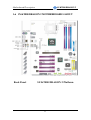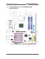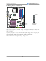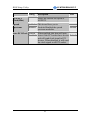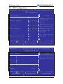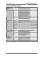
1
SY-KT880 DRAGON 2
Motherboard
****************************************************
AMD Athlon & Duron Processors Supported
VIA KT880 AGP/PCI Motherboard
200/266/333/400 MHz Front Side Bus supported
ATX Form Factor
****************************************************
User's Manual
SOYO™
SY-KT880 DRAGON 2
Copyright © 2004 by SOYO Computer Inc.
Trademarks:
SOYO is a registered trademark of SOYO Computer Inc. All trademarks are
properties of their owners.
Product Rights:
All names of the product and corporate mentioned in this publication are used for
identification purposes only. The registered trademarks and copyrights belong to
their respective companies.
Copyright Notice:
All rights reserved. This manual has been copyrighted by SOYO Computer Inc. No
part of this manual may be reproduced, transmitted, transcribed, translated into any
other language, or stored in a retrieval system, in any form or by any means, such as
by electronic, mechanical, magnetic, optical, chemical, manual or otherwise,
without permission in writing from SOYO Computer Inc.
Disclaimer:
SOYO Computer Inc. makes no representations or warranties regarding the contents
of this manual. We reserve the right to amend the manual or revise the specifications
of the product described in it from time to time without obligation to notify any
person of such revision or amend. The information contained in this manual is
provided to our customers for general use. Customers should be aware that the
personal computer field is subject to many patents. All of our customers should
ensure that their use of our products does not infringe upon any patents. It is the
policy of SOYO Computer Inc. to respect the valid patent rights of third parties and
not to infringe upon or to cause others to infringe upon such rights.
Disclaimer:
Please be advised that some SOYO motherboards are designed with overclocking
features and may allow users to run the components beyond manufacturer's
recommended specifications. Overclocking beyond manufacturer's specifications is
not recommended nor endorsed by SOYO, Inc. and will void your manufacturer's
warranty. Overclocking beyond manufacturer's specifications is not encouraged and
should be assumed at the user's own risk. Unsafe overclocking can damage the user's
system or cause serious personal injury. If the user is unsure or in doubt about
overclocking, please seek professional advise. SOYO, Inc. is not responsible for any
direct or indirect damage resulting from overclocking.
Restricted Rights Legend:
Use, duplication, or disclosure by the Government is subject to restrictions set forth
in subparagraph (c)(1)(ii) of the Rights in Technical Data and Computer Software
clause at 252.277-7013.
About This Guide:
This Quick Start Guide can help system manufacturers and end users in setting up
and installing the Motherboard. Information in this guide has been carefully checked
for reliability; however, to the correctness of the contents there is no guarantee given.
The information in this document is subject to amend without notice.
For further information, please visit our Web Site on the Internet. The address is
"http://www.soyo.com.tw".
C
FC
Tested To Comply
With FCC Standards
FOR HOME OR OFFICE USE
Edition: April 2004
Version P1.0
100%
KT880 DRAGON 2 SERIES
ii
POST CONSUMER
RECYCLED PAPER
SY-KT880 DRAGON 2
Table of Contents
Table of Contents
CHAPTER 1 MOTHERBOARD DESCRIPTION ................................1
1-1
INTRODUCTION.......................................................................1
1-2
UNPACKING THE MOTHERBOARD .....................................1
1-3
KEY FEATURES........................................................................3
1-4
HANDLING THE MOTHERBOARD .......................................4
1-5
ELECTROSTATIC DISCHARGE PRECAUTIONS..................5
1-6
SY-KT880 DRAGON 2 MOTHERBOARD LAYOUT.....................6
1-7
SY-KT880 DRAGON 2 MOTHERBOARD COMPONENTS...7
CHAPTER 2 HARDWARE INSTALLATION.....................................14
2-1
PREPARATIONS......................................................................14
2-2
INSTALLATION GUIDE .........................................................15
Step 1 Install the CPU.......................................................................14
Step 2 Install Memory Module ..........................................................22
Step 3 Install Expansion Card ...........................................................23
A. IDE Device Installation (HDD, CD-ROM)...................................25
B. Floppy Drive Installation..............................................................26
C. Front Panel Connections..............................................................28
D. Back Panel Connections...............................................................30
E. Other Connections ........................................................................35
F. ATX12V Power Supply ..................................................................41
G. CMOS Clear (JP5) .......................................................................43
Step 5 Power On................................................................................43
2-3
QUICK BIOS SETUP...............................................................44
CHAPTER 3 BIOS SETUP UTILITY ..................................................46
3-1
SOYO COMBO FEATURE......................................................49
3-2
STANDARD BIOS FEATURES...............................................56
3-3
ADVANCED BIOS FEATURES ..............................................57
3-4
PCI/PNP RESOURCE MANAGEMENT.................................70
3-5
PC HEALTH STATUS ..............................................................72
iii
SY-KT880 DRAGON 2
Table of Contents
3-6
BOOT CONFIGURATION SETUP .........................................74
3-7
BIOS SECURITY FEATURES.................................................77
3-8
EXIT .........................................................................................77
CHAPTER 4 VIA 8237 SERIAL ATA DRIVER INSTALLATION....79
CHAPTER 5 ALI M5281 IDE3/4 DRIVER INSTALLATION ...........82
CHAPTER 6 ALI M5281 SATA3/4 DRIVER INSTALLATION ........85
CHAPTER 7 DRIVERS INSTALLATION ..........................................88
CHAPTER 8 USB 2.0 DRIVER INSTALLATION..............................96
APPENDIX A ALI M5281 .......................................................................97
APPENDIX B TROUBLESHOOTING.................................................106
APPENDIX C CONTACT INFORMATION ........................................ 113
iv
SY-KT880 DRAGON 2
Motherboard Description
Chapter 1
MOTHERBOARD DESCRIPTION
1-1 INTRODUCTION
The SY-KT880 DRAGON 2 AGP/PCI motherboard is a high performance
Socket A, ATX form-factor system board. The SY-KT880 DRAGON 2
uses VIA Chipset technology and supports AMD Socket class processors.
This motherboard is fully compatible with industry standards and adds
many technical enhancements.
1-2 UNPACKING THE MOTHERBOARD
When unpacking the motherboard, check for the following items:
The SY-KT880 DRAGON 2 AGP/PCI motherboard
The user manual
The Installation and Bonus Pack CD-ROM
Four Serial ATA Cables
Two IDE Device ATA 66/100/133 Flat Cable
One Floppy Disk Drive Flat Cable
One Heat Sink Compound
1
SY-KT880 DRAGON 2
Motherboard Description
One COM port/Printer port Bracket
One Back Panel
Warning: Do not unpack the motherboard from its anti-static
packaging until you are ready to install it.
Like most electronic equipment, your motherboard may be damaged by
electrostatic discharge. To avoid permanent damage to components ground
yourself while working by using a grounding strap. Otherwise, ground
yourself frequently by touching the unpainted portion of the computer
chassis to drain the static charges.
Handle the motherboard carefully, holding it by the edges.
You are now ready to start the installation.
2
SY-KT880 DRAGON 2
Motherboard Description
1-3 KEY FEATURES
Supports AMD 462 pins Socket A processors:
CPU
Athlon XP (Palomino/Thoroughbred/Barton)
(200/266/333/400 MHz FSB)
Duron/Morgan
Chipset
Memory
VIA KT880/ 8237 Chipset
Supports PC2100, PC2700 and PC3200 DDR
(non-registered and ECC) memory modules.
AGP
1x AGP Pro master 4x/8x slot (1.5v only)
PCI
5x 32-bit bus master PCI slots
ITE IT8705F (GX) Super I/O controller supporting:
Floppy disk controller
Parallel port (SPP, EPP and ECP compliant)
I/O
IrDA compatible infrared port
PS/2 Keyboard and mouse
Hardware monitor for monitoring temperatures,
voltages and fan speeds in the system.
VIA VT8237 Integrated Parallel ATA controller
supporting up to 4x UDMA 33/66/100/133
Parallel ATA devices.
VIA VT8237 Integrated Serial ATA controller
(SATA1/2) supporting up to 2x UDMA 150 hard
disks in normal or RAID 0,1 mode.
Storage
ALi M5281 Integrated Parallel ATA controller
(IDE3/4) supporting up to 4x UDMA
33/66/100/133 Parallel ATA devices. Support
RAID 0, 1, 0+1 mode.
ALi M5281 Integrated Serial ATA controller
(SATA3/4) supporting up to 2x UDMA 150 hard
disks in normal or RAID 0, 1 mode.
USB 2.0
8x USB 2.0 compliant ports (4 on rear IO panel, 4 pin
headers.)
IEEE 1394
Onboard VIA VT6307 IEEE1394 Firewire controller
with 2x pin header
3
SY-KT880 DRAGON 2
Motherboard Description
Sound
Network
AC97 C-Media CMI9780 8 Channel CODEC
Onboard VIA VT6122 100Base-T and
1000BASE-T(Gigabit) Ethernet controller, supporting
Wake-On-Lan (WOL).
Power Failure resume function to allow the system
to turn on or off after a power failure, which is
indispensable for server systems.
BIOS
Wake On Ring and Power On by Alarm to allow
your system to wake up from suspend or power on
through the modem or RTC alarm.
Multiple boot, allowing your system to boot from
for example CD-ROM
1-4 HANDLING THE MOTHERBOARD
To avoid damage to your motherboard, please follow these simple rules
while unpacking:
Before handling the motherboard, ground yourself by grasping an
unpainted portion of the system's metal chassis.
Remove the motherboard from its anti-static packaging. Hold the
motherboard by the edges and avoid touching its components.
Check the motherboard for damage. If any chip appears loose, press
carefully to set it firmly in its socket.
Warning: Do not apply power if the motherboard appears
damaged. If there is damage to the board, contact your dealer
immediately.
4
SY-KT880 DRAGON 2
Motherboard Description
1-5 ELECTROSTATIC DISCHARGE PRECAUTIONS
Be sure to ground yourself before handling the motherboard or other system
components. Electrostatic discharge can easily damage the components.
Note that you must take special precautions when handling the motherboard
in dry or air-conditioned environment.
To protect your equipment from electrostatic discharge, take the following
precautions:
Do not remove the anti-static packaging until you are ready to install.
Ground yourself before removing any system component from its
protective anti-static packaging. (To ground yourself, grasp the expansion
slot covers or other unpainted portions of the computer chassis).
Frequently ground yourself while working or use a grounding strap.
Handle the motherboard by its edges and avoid touching its
components.
5
SY-KT880 DRAGON 2
Motherboard Description
1-6 SY-KT880 DRAGON 2 MOTHERBOARD LAYOUT
Back Panel
SY-KT880 DRAGON 2 Platform
6
SY-KT880 DRAGON 2
Motherboard Description
1-7 SY-KT880 DRAGON 2 MOTHERBOARD
COMPONENTS
7
SY-KT880 DRAGON 2
Motherboard Description
CPU Cooling Fan (CPUFAN3) connector
A
With these connectors you can attach the CPU fan or fans to your
motherboard. They supply power and (in the case of CPUFAN1)
allow you to monitor the speed of the FAN via the SOYO
Hardware Monitor software or via CMOS setup. For more details
on the lay-out of these connectors, check the CPU Cooling FAN
(CPUFAN1, CPUFAN2, CPUFAN3) paragraph on page 36.
Front panel I/O Connector (J30)
B
This connector allows you to extend your earphone, microphone,
Line-in connector to your front panel. Check the Front panel I/O
Connector (J30) paragraph on page 39 for a lay-out of this header.
ATX Power Supply connector
C
This connector is to connect the ATX connector of your ATX 12V
compliant power supply to the motherboard. For more details on
this connector, please check the F. ATX12V Power Supply
paragraph on page 41.
+12V Power Connector
D
This is where the Power Supply's +12V ATX connector goes. For a
lay-out of this connector please check the F. ATX12V Power
Supply paragraph on page 41.
VIA KT880 North Bridge
E
The advanced FastStream64 DDR400 Memory Controller on the
VIA KT880 interweaves with the 400MHz Front Side Bus to
provide a perfectly balanced subsystem, greatly reducing data
latency and enabling searing performance from the latest AMD
Athlon™ XP processors. In addition, the KT880 supports the very
latest I/O technologies including AGP8X, deriving maximum
performance from the most powerful graphics processors.
Socket 462 (Socket A) connector
F
This is the Zif (Zero Insertion Force) socket for your AMD
Athlon®, Athlon XP®, Duron® or Morgan® CPU. For more
information on how to install your CPU, check the CPU Mount
Procedure paragraph on page 17.
8
SY-KT880 DRAGON 2
Motherboard Description
G
H
I
J
K
ABR (Anti Burn Regulator) Jumper
SOYO's ABR (Anti Burn Regulator) is specially designed
hardware circuits that works hand in hand with the CPU’s internal
sensor in monitoring the temperature of the CPU and prevent it
from overheating. This jumper enables or disables this function.
For more information, please check the ABR (Anti Burn
Regulator) paragraph on page 21.
CPU Cooling Fan (CPUFAN1, 2) connectors
With these connectors you can attach the CPU fan or fans to your
motherboard. They supply power and (in the case of CPUFAN1)
allow you to monitor the speed of the FAN via the SOYO
Hardware Monitor software or via CMOS setup. For more details
on the lay-out of these connectors, check the CPU Cooling FAN
(CPUFAN1, CPUFAN2, CPUFAN3) paragraph on page 36.
DDR DIMM Banks
These 4, 184 pin memory slots are to install your system memory
in. They support up to 4 GB of memory. For more details check the
Step 2 Install Memory Module paragraph on page 22.
Bus Mastering EIDE/ATAPI Ports
These connectors are to attach your IDE devices to. Each
connector can support up to 2 IDE devices, 1 master and 1 slave.
Please check the A. IDE Device Installation (HDD, CD-ROM)
paragraph on page 25 for more details.
VIA VT8237 South Bridge
Featuring the first ever integrated combined Serial ATA/RAID
controller, the VT8237 is the most advanced South Bridge
available on the market today. With its integrated dual channel
native Serial ATA/RAID controller supplying 150MB/s of
bandwidth per port and support for RAID 0 & RAID 1, the
VT8237 delivers the highest disk data transfer rates for maximum
system performance and provides the most advanced fault tolerant
solution for optimum data integrity. The VT8237 also features
support for up to four Parallel ATA-133 devices, extending
flexibility to the system integrator by allowing for mainstream or
value configurations leveraging the existing technology standard.
Additional features on the VIA VT8237 South Bridge include
support for up to eight USB 2.0 ports, and integrated PCI support.
9
SY-KT880 DRAGON 2
Motherboard Description
L
M
N
O
P
Q
R
S
3V Lithium Battery
This battery supplies power to the CMOS RAM. As long as the
battery supplies enough power, the contents of your CMOS RAM
will be valid. CMOS RAM contents are configured by CMOS
setup, and can be cleared by JP5. For more details on this check the
G. CMOS Clear (JP5) paragraph on page 43.
Onboard buzzer
This buzzer gives off system beeps.
Chassis Cooling Fan (CHAFAN1, 3)
This connector is to connect your chassis fan to your motherboard.
This motherboard supports up to 3 chassis fans. It allows you to
monitor the speed of CHAFAN1 in CMOS setup or by using the
SOYO Hardware Monitor software. Please check the Chassis
Cooling Fan (CHAFAN1,CHAFAN2, CHAFAN3) paragraph on
page 37 for more details.
CMOS Clear Jumper (JP5)
This jumper allows you to clear your CMOS RAM contents in
order to reset your system configuration. For more details on this
check the G. CMOS Clear (JP5) paragraph on page 43.
Floppy disk connector
This motherboard supports one floppy drive. For more details,
please check the B. Floppy Drive Installation paragraph on page
27.
IDE RAID Ports
This IDE port (IDE 3, 4) can be used as normal IDE port or in a
RAID configuration and are controlled by ALi M5281 chip.
ATAPI devices will not work on these ports. For more details,
please check the A. IDE Device Installation (HDD, CD-ROM)
paragraph on page 25.
5V Stand-By Indicator LED
The power supply will always supply a 5V standby voltage to your
motherboard so that it can power on via for example Wake On Lan
technology. This LED shows that your power supply is supplying
this standby voltage to your motherboard.
J25 Front panel connections header
This header contains the connections to the front panel on the case.
For more details, please check the C. Front Panel Connections
paragraph on page 28.
10
SY-KT880 DRAGON 2
Motherboard Description
T
U
V
W
X
Y
Z
ALi M5281 Serial ATA/IDE RAID chip
The M5281 provides personal computer systems with PCI device
solution of the highest integration: It includes two Serial-ATA Host
controllers (SATA3/4) for supporting a total of 2 ports, two fully
Parallel-ATA Host controller (IDE3/4) for supporting two single
channel.
IEEE1394 Firewire connector
These connectors allow you to attach IEEE 1394 connectors or
devices to the motherboard. The lay-out can be found in the IEEE
1394 (Firewire) Connector (FW1/FW2) paragraph on page 40.
SATA Connectors
These connectors allow you to attach one UDMA 150 hard disk to
each connector. SATA1/2 are controlled by VIA VT8237 chip, and
SATA 3/4 are controlled by the ALi M5281 chip, and SATA1~4 all
can support RAID 0 and 1. For more information on these
connectors check the A. IDE Device Installation (HDD,
CD-ROM) paragraph on page 25.
VIA VT6307 IEEE 1394 Firewire controller
The VIA Fire II VT6307 provides direct connectivity between the
PCI and 1394 serial buses. With three ports, the VIA Fire II
VT6307 is designed to provide scalability and manageability in
IEEE 1394 network solutions for home networking and multiple
PC access to a single internet connection. Each individual port
detects connected device types and automatically configures data
speeds to either 100, 200 or 400 Mbps, speeds well suited to
multi-streaming I/O requirements. A programmable PCI power
management mode (specification 1.1) shuts down power to
unconnected ports while the sleep function maximizes power
efficiency of connected ports.
USB 2.0 connectors
These connectors support 2 USB 2.0 ports per connector. For
details on the lay-out, please check the Universal Serial Bus
(USB1/USB2/USB3/USB4, USB20_1/USB20_2) paragraph on
page33.
COM Port
LPT Port
11
SY-KT880 DRAGON 2
Motherboard Description
AA
AB
AC
AD
AE
AF
AG
Flash BIOS
This chip contains the system BIOS firmware, and is software
upgradable. It's size is 2Mbit. For updates of your Flash BIOS,
please go to http://www.soyousa.com. For details on how to setup
your BIOS, please go to the Quick BIOS Setup chapter on page
44.
ITE IT8705F Super I/O Chip
IT8705F is a LPC Interface based highly integrated Super I/O.
IT8705F provides the most commonly used legacy Super I/O
functionality plus the latest Environment Control initiatives, such
as Hardware Monitor, Fan Speed Controller and ITE’s
“SmartGuardian” function. The device’s LPC interface complies
with Intel “LPC Interface Specification Rev. 1.0” (Sept. 29, 1997).
IT8705F meets the “Microsoft PC98/99/2001 System Design
Guide” requirements and is ACPI compliant.
Serial Infrared (IrDA) device header
This header allows you to connect an IrDA receiver to the
motherboard. You can find the lay-out in the Standard Infrared
(SIRCON) paragraph on page 35.
CDIN CDROM Audio In connectors
This connector is to attach your analog audio output channel from
your CDROM or DVD drive to your motherboard. Please check
for more details on page 38 in the CD Line-in/AUXIN
(CDIN1,AUXIN1) paragraph.
AUXIN CDROM Audio In connectors
This connector allows you to attach a second CDROM analog
audio out output to your motherboard. Please check for more
details on page 38 in the CD Line-in/AUXIN (CDIN1,AUXIN1)
paragraph.
AC97 C-Media CMI9780 8 Channel CODEC
32 bit PCI slots
These are the motherboard's 3.3v busmastering PCI slots,
compliant to PCI specification v2.2. Please check the Step 3
Install Expansion Card paragraph on page 23 for more details.
12
SY-KT880 DRAGON 2
Motherboard Description
AH
AI
AJ
AK
VIA VT6122 LAN Chip
Onboard VIA VT6122 100Base-T and 1000BASE-T(Gigabit)
Ethernet controller, supporting Wake-On-Lan (WOL).
Chassis Cooling Fan (CHAFAN2)
This connector is to connect your chassis fan to your motherboard.
This motherboard supports up to 3 chassis fans. It allows you to
monitor the speed of CHAFAN2 in CMOS setup or by using the
SOYO Hardware Monitor software. Please check the Chassis
Cooling Fan (CHAFAN1,CHAFAN2, CHAFAN3) paragraph on
page 37 for more details.
AGP Pro Slot
This is the AGP expansion slot for your video card. Note that it can
only work with 1.5v AGP cards. For more information, check the
Step 3 Install Expansion Card paragraph on page 23.
Back panel connectors
These connectors allow you to attach the external devices to the
back of your PC. Please check the Back Panel Connections
paragraph on page 30 for more details.
13
SY-KT880 DRAGON 2
Hardware Installation
Chapter 2
HARDWARE INSTALLATION
Congratulations on owning a-SY-KT880 DRAGON 2. You are about to
install and connect your new motherboard.
Note: Do not unpack the motherboard from its protective
anti-static packaging until you have made the following
preparations.
2-1 PREPARATIONS
Gather and prepare all the following hardware equipment to complete the
installation successfully:
1.
Socket A processor with built-in CPU cooling fan (boxed type)
2.
DDR RAM module (s)
3.
Computer case and chassis with adequate power supply unit
4.
Monitor
5.
PS/2 Keyboard
6.
Pointing Device (PS/2 mouse)
7.
Speaker(s) (optional)
8.
Disk Drives: HDD, CD-ROM, Floppy drive…
9.
External Peripherals: Printer, Plotter, and Modem (optional)
10.
Internal Peripherals: Modem and LAN cards (optional)
14
SY-KT880 DRAGON 2
Hardware Installation
2-2 INSTALLATION GUIDE
We will now begin the installation process. Please follow the step-by-step
procedure designed to lead you to a complete and correct installation.
Step 1- Install the Central Processing Unit (CPU)
Step 2- Install memory modules
Step 3- Install expansion cards
Step 4- Connect cables, case wires, and power supply
Step 5- Power on and enter BIOS setup
Step 6- Install supporting software tools. See Chapter 4 for more info.
Warning: Turn off the power to the motherboard, system chassis,
and peripheral devices before performing any work on the
motherboard or system.
BEGIN THE INSTALLATION
Step 1 Install the CPU
CPU Mount Procedure: To mount the AMD® K7 Athlon XP or DuronTM
processor that you have purchased separately, follow these instructions.
1.
Lift the socket handle up to a vertical position.
15
SY-KT880 DRAGON 2
Hardware Installation
2.
Align the blunt edge of the CPU with the matching pinhole distinctive
edge on the socket.
3.
Seat the processor in the socket completely and without forcing.
4.
Then close the socket handle to secure the CPU in place.
Remember to connect the CPU Cooling Fan to the
appropriate power connector on the motherboard. The fan is a
key component that will ensure system stability. It prevents
overheating, therefore prolonging the life of your CPU.
16
SY-KT880 DRAGON 2
Hardware Installation
CPU Fan Installation
Your Socket A processor kit comes with a cooling fan. Mount the fan on the
processor according to the instructions provided by the manufacturer. The
fan is a key component that will ensure system stability. The fan prevents
overheating, therefore prolonging the life of your CPU.
Note: Remember to connect the fan to the appropriate power source.
CPU Fan Mount Procedure: To prevent scratch or damage to the
motherboard, please follow the instructions on how to mount the CPU fan
properly.
1. Apply thermal paste to the die of the CPU.
17
SY-KT880 DRAGON 2
Hardware Installation
2. Make sure that the retaining clip is in this position before trying to install
the heatsink. Notice that the clip is not symmetrical. The long end always
attaches to the top of the socket (the end that reads “Socket 462”), while
the short end engages the bottom of the socket. No matter which heatsink
is used, the clip is always installed in the same manner.
3.
To install this clip, push firmly only on the end of the clip. To install the
clip, typically requires 12 to 24 pounds of force.
18
SY-KT880 DRAGON 2
Hardware Installation
4. The fans power connector should be connected to CPUFAN1.
Note: If the fan is defective or Power connector is not connected to
CPUFAN1, the system will enable Fan Off Control function. See
page 20 for more information on FOC function.
When the CPU temperature exceeds the temperature set in the CPU
Temp. Protection in the BIOS setup, SOYO’s Anti burn Regulator
(ABR) will automatically shutdown the system and beep until the
power button is pressed for one time. For more info about ABR, check
page 25.
19
SY-KT880 DRAGON 2
Hardware Installation
FOC ( Fan-Off Control )
The newly designed SOYO “FOC” is based on the concept of total
protection for CPU, which is very different from currently seen on the
market. The H/W control function is used to see a passive security system of
monitoring and warning. S/W Simultaneous Signal Follow-ups techniques
and Auto Power Off System are included to prevent all possible damage
caused by the malfunctioning of the CPU fan. With the help of “O/S On
Time Monitoring And Warning” function, provided by the H/W monitoring
system, the double-protection purpose is achieved.
“FOC” includes the following functions:
(1) Simultaneous Signal Follow Ups: Before the system enters the O/S,
H/W will detect the signals of the CPU fan pins, get their revolution
information and send it to the BIOS.
(2) Auto Power Off System: If the BIOS receives the information of
CPU fan revolution, it continues to function normally. If no signal is
received, it will inform the system and disconnects the power
supply immediately to protect the CPU from overheating.
Note: The following must be observed to secure the normal functioning of
“Fan-Off Control”:
1. FOC only works on CPUFAN 1.
2. CPU fan with sensor pins must be used.
3. CPU fans approved by AMD are strongly recommended.
The “HOT KEY” function is provided for the CPU fans without sensor pins,
to avoid the power off. Users may press the “Insert” key to jump over the
“Power Off” mode; go to the BIOS and disable “FOC”. Now system can be
booted normally.
We provide the following user-friendly protection features:
1. Fan-Off Control: The motherboard detects the status of the CPU fan
and protects the CPU by automatically disconnecting the power
supply. The default value of this function is Enable. After booting
20
SY-KT880 DRAGON 2
Hardware Installation
up, the user may disable it.
2. Heat Dissipation Paste: Heat Dissipation Paste is included for all
Socket-A motherboards, to enhance the heat dissipation capability.
Furthermore, we strongly recommend our users to enable the function of
H/W monitoring in the BIOS. This function, together with the FOC,
provides the total protection to the CPU and allows it to maximize its
performance.
ABR (Anti Burn Regulator)
SOYO's ABR (Anti Burn Regulator) is specially designed hardware circuits
that works hand in hand with the CPU’s internal sensor in monitoring the
temperature of the CPU and prevent it from overheating.
Once the heat accumulated in the CPU is over the set limit. ABR will
automatically shut down the system power and warns you with a beeping
sound. To de-activate the beeping sound, un-plug the AC power cord. We
recommend you to check the cause of the overheating and let the processor
cool down before powering on the system.
Note: ABR supports AMD XP and Morgan CPU. Duron and
Thunderbird CPU are not supported
Some early versions of the 2400+ and 2600+ XP CPUs when used in
this motherboard will automatically activate the ABR function, thus
making a beeping sound and shut down your system. If this
compatibility issue arises, you need to disable the ABR function via
the ABR hardware jumper.
Setting
Enabled
Disabled
ABR Jumper
1 2
1 2
21
SY-KT880 DRAGON 2
Hardware Installation
Step 2 Install Memory Module
DIMA1
DIMA2
DIMB1
DIMB2
□
□
This motherboard supports two Dual Channels to your memory. Note that
you can use normal DDR memory for Dual Channel to work. Also note that
for Dual Channel to work 2 or 4 modules of equal size and specifications
have to be installed.
The largest memory capacity possible is 4GB. On this motherboard,
DRAM speed can be set independent from the CPU front side bus speed.
Note that when installing 4GB of memory, your total memory will be less
than 4GB. The reason for this is that the BIOS, PCI and AGP cards claim
part of your CPUs address space.
22
SY-KT880 DRAGON 2
Hardware Installation
Memory Configuration Table
If you want to use the Dual Channel feature, please follow the memory
configuration table below:
Step 3 Install Expansion Card
The motherboard has 1 AGP slot and 5 PCI slots.
1.
Read the related expansion card’s instruction document before inserting
the expansion card into the computer.
2.
Press the expansion card firmly into expansion slot in motherboard.
3.
Be sure the metal contacts on the card are indeed seated in the slot.
4.
Replace the screw to secure the slot bracket of the expansion card.
5.
Install driver for the operating system you use.
NOTE: Some high-speed memory modules may need to be set “DDR
Voltage Select” to 2.7V at BIOS when using.
23
SY-KT880 DRAGON 2
Hardware Installation
AGP Pro Slot
This motherboard supports AGP 4x/8x/Pro VGA CARD.
DO NOT remove the safety tab underneath it if you will be using an AGP
card without a retention notch. Removing may cause the card to shift and
may cause damage to your card, slot, and motherboard. Remove ONLY
when you will be using an AGP Pro card. You can use a pen tip to remove
the tab from the bay.
24
SY-KT880 DRAGON 2
Hardware Installation
Step 4 Connect cables, case wires, and power supply
A. IDE Device Installation (HDD, CD-ROM)
IDE 1
IDE 2
Primary
IDE
Secondary
IDE
Pin-1
Pin-1
□
□
IDE3 IDE4
RAID IDE
SATA2
SATA1
SATA3
SATA4
This Motherboard offers two primary (IDE1, IDE3) IDE device connectors,
2 secondary IDE device connectors (IDE2, IDE4) and 4 tertiary serial ATA
ports. IDE1 and IDE2 can support up to four high-speed Ultra DMA
33/66/100/133 HDD or CD-ROM. IDE3 and IDE4 can support up to 4 high
speed Ultra DMA 33/66/100/133 HDD. SATA1~4 can support up to 4 ATA
150 SATA hard disks.
There are 4 parallel ATA HDD connectors (IDE1, IDE2, IDE3, IDE4) and 4
serial ATA connectors on the motherboard. SATA1, SATA2, SATA3 and
SATA4 are provided for SATA RAID or standard SATA function. This
Motherboard can support up to 12 HDDs.
25
SY-KT880 DRAGON 2
Hardware Installation
Note:.
Creating a RAID 0, 1, 0+1 array on IDE3/IDE4 is possible
Creating a RAID 0, 1 array on SATA1/SATA2 is possible.
Creating a RAID 0, 1 array on SATA3/SATA4 is possible.
Parallel ATA connectors
Connect the black end of the ATA66/100/133 flat cable to the IDE device
(HDD or CD-ROM) and plug the blue end to the primary (IDE1, IDE3) or
secondary (IDE2) directionally keyed IDE connector on the Motherboard.
The ATA66/100/133 cable is backward compatible with ATA33 HDDs.
Serial ATA connectors
You can also plug the serial ATA cable into the serial ATA connector of the
motherboard. The other end of the SATA cable goes into your SATA device.
26
SY-KT880 DRAGON 2
Hardware Installation
B. Floppy Drive Installation
Pin-1
□
□
FLP
Floppy Driver
Connector
The system supports 4 possible floppy drive types: 720 KB, 1.2 MB, 1.44
MB, 2.88 MB.
Connect one side of the 34-pin flat cable to the floppy drive and plug the
other end to the floppy drive connector on the motherboard.
This motherboard can support only 1 floppy drive.
27
SY-KT880 DRAGON 2
Hardware Installation
C. Front Panel Connections
Speaker
Power LED
+
1
Reset
_
+
1
PWRBT
+ _+ _
ACPI LED HDD LED
□
□
Plug the computer case's front panel devices to the corresponding headers
on the motherboard.
1.
Power LED
Please install according to the following pin assignment: pin 1,3 are for
Power LED.
Power LED
Pin Assignment
VCC
NC
28
GND
_
SY-KT880 DRAGON 2
Hardware Installation
2. Reset
Plug the Reset push-button cable into the 2-pin Reset header on the
motherboard. Pushing the Reset button on the front panel will cause the
system to restart the boot-up sequence.
Reset Pin Assignment
1
Power Good
3.
GND
Speaker
Attach the 4-pin PC speaker cable from the case to the Speaker header on
the motherboard.
Speaker Pin Assignment
VCC
4.
NC NC
Speaker out
IDE LED
Attach the 2-pin IDE device LED cable to the corresponding IDE LED
header on the motherboard. This will cause the LED to light up when an IDE
device (HDD, CD-ROM) on IDE 1,2 or SATA 1,2 device is active.
HDD LED Pin Assignment
+
_
LED Anode LED Cathode
29
SY-KT880 DRAGON 2
Hardware Installation
5. ATX Power On/Off Switch
Attach the 2-pin momentary type switch to the PWRBT header for turning
ON or OFF your ATX power supply.
PWRBT Pin Assignment
1
Power On/Off
GND
D. Back Panel Connections
All external devices such as the PS/2 keyboard, PS/2 mouse, USB can be
plugged directly onto the motherboard back panel.
Only after you have fixed and locked the motherboard to the computer case
can you start connecting the external peripheral devices.
When connecting an external device, use the following figure to locate and
identify which back panel connector to plug the device to.
PS/2 KB PS/2 Mouse
Connector Connector
USB3 / USB4
USB1 / USB2 / LAN
CENTER/Bass
Surround
Back Surround
MIC IN
□
Line out / Front out
□
Line in
Pin 1
Printer Port (LPT)
2
10
1
9
COM Port
30
SY-KT880 DRAGON 2
Hardware Installation
1. Onboard Serial Ports (COM)
External peripherals that use serial transmission scheme include:
-
serial mouse
-
modem
Plug the serial device cables directly into the COM1/COM2 9-pin male
connectors located at the rear panel of the motherboard.
COM Pin Assignment
NDSR1#
3
4
NRTS1#
5
6
8
NCTS1
NRI1#
1
NRXD1
NTXD1
NDTR1#
GND
2.
2
NDCD#
7
9
4
3
Parallel Port PRT (LPT)
This parallel port is used to connect the printer or other parallel devices.
Plug the parallel device cable into the 25-pin female connector located at the
rear panel of the motherboard.
-STB
PRD0
PRD1
PRD2
PRD3
PRD4
PRD5
PRD6
PRD7
ACK#
BUSY
PE
SLCT
14
15
16
17
18
19
20
21
22
23
24
25
1
2
3
4
5
6
7
8
9
10
11
12
13
31
AFD#
ERR#
INIT#
SLIN#
GND
GND
GND
GND
GND
GND
GND
GND
SY-KT880 DRAGON 2
Hardware Installation
3. PS/2 Keyboard
Plug the keyboard jack directly into the 6-pin female PS/2 keyboard
connector located at the rear panel of the motherboard.
Pin6
NC
Pin4
VCC
Pin2
NC
4.
Pin5
KBD Clock
Pin3
GND
Pin1
KBD DATA
PS/2 Mouse
Similarly, plug the mouse jack directly into the 6-pin female PS/2 mouse
connector.
Pin6
NC
Pin5
Mouse Clock
Pin4
VCC
Pin2
NC
Pin3
GND
Pin1
Mouse DATA
32
SY-KT880 DRAGON 2
Hardware Installation
5. Universal Serial Bus (USB1/USB2/USB3/USB4, USB20_1/USB20_2)
This motherboard provides eight USB ports for your additional devices.
Plug the USB device jack into the available USB connector
USB1/USB2/USB3/USB4.
-
Standard device drivers come with the Win98 for commonly used USB
devices.
-
With Win95, use the flow UHCI specifications. To use USB devices
under Win95, usually you have to install the device that driver comes
with the USB device you have purchased.
USB20_1 and USB20_2 are available. To make use of these USB ports,
purchase a USB cable from your dealer. The lay-out of USB20_1, USB20_2
are as follows:
GND
GND
(+)Data
10
9
4
8
3
GND
(+)Data
(-)Data
7
2
(-)Data
Power
6
1
Power
USB1, USB2, USB3, USB4, USB20_1 and USB20_1 supports USB 2.0
devices.
33
SY-KT880 DRAGON 2
Hardware Installation
6. Onboard audio (Audio Speakers connections)
When using 2-channel speaker, connect the speaker cable to Line-out.
If you’re using 2, 4, 6 or 8 channel speaker, make sure that the audio
software is set for 2, 4, 6 or 8 channel speaker system.
Line in
CENTER/Bass
Line out / Front out
Surround
Back Surround
MIC IN
Note: When using SPDIF, please make sure to set the audio software
for SPDIF, and CENTER/Bass (orange color) will be the optical Line
out. Lin in (blue color) will be the optical Line-in.
34
SY-KT880 DRAGON 2
Hardware Installation
E. Other Connections
1.
Standard Infrared (SIRCON)
Plug the 5-pin infrared device cable to the SIRCON header.
This will enable the infrared transfer function. This motherboard meets both
the ASKIR and HPSIR specifications.
Please install according to the following pin assignment:
Standard Infrared
(SIRCON) Connector
SIRCON Pin Assignment
1 2 3 4 5
VCC
IRRX
GND
35
IRTX
SY-KT880 DRAGON 2
Hardware Installation
2.
Cooling Fan Installation
(1) CPU Cooling FAN (CPUFAN1, CPUFAN2, CPUFAN3)
After you have seated the CPU properly on the processor, attach the 3-pin
fan cable to the CPUFAN1 connector on the motherboard.
To avoid any damage to the system, install according to the following pin
assignment:
CPU Cooling Fan
(CPUFAN1, CPUFAN2, CPUFAN3)
CPUFAN Pin Assignment
CPUFAN1
1
GND
2
12V
3
SENSOR
CPUFAN2
1
GND
2
3
NC
12V
CPUFAN3
3
NC
2
12V
36
1
GND
SY-KT880 DRAGON 2
Hardware Installation
(2) Chassis Cooling Fan (CHAFAN1,CHAFAN2, CHAFAN3)
Some chassis also feature a cooling fan. This motherboard features a
CHAFAN connector to provide 12V power to the chassis fan. Connect the
cable from the chassis fan to the CHAFAN 3-pin connector. Install
according to the following pin assignment:
Classis Cooling Fan
(CHAFAN1, CHAFAN2, CHAFAN3)
CHAFAN Pin Assignment
CHAFAN1
1
GND
2
12V
3
SENSOR
CHAFAN2
3
NC
2
12V
1
GND
CHAFAN3
1
GND
2
12V
3
NC
Note: CPUFAN must be installed on this motherboard, while
CHAFAN is optional.
37
SY-KT880 DRAGON 2
Hardware Installation
3. CD Line-in/AUXIN (CDIN1,AUXIN1)
This motherboard provides two CD-Line in connectors. Please connect the
4-pin audio cable from your CD-ROM drive to either CDIN1 or AUXIN1.
(It fits in only one, depending on the cable that came with your CD-ROM
drive)
Please install according to the following pin assignment:
38
SY-KT880 DRAGON 2
Hardware Installation
4. Front panel I/O Connector (J30)
You can connect the Line-out /MIC in to the front panel of your PC case (If
this option is available in your PC case). When you connect this J30, please
make sure J30 and your cable connector pin definitions to match. This
connector has the following pin assignment:
1
2
AUD_F_R
HP_ON
AUD_F_L
3
5
7
9
4
6
8
10
VCC
AUD_R_R
GND
LINE_I_R
LINE_I_L
13
15
14
16
LINE_R_R
LINE_R_L
MIC_L
MIC_R
39
GND
AUD_R_L
SY-KT880 DRAGON 2
Hardware Installation
7. IEEE 1394 (Firewire) Connector (FW1/FW2)
This motherboard provides 3 IEEE 1394 ports for your Firewire devices.
Standard drivers are supplied with the operating system for commonly used
Firewire devices.
FW1 and FW2 are available. You can connect them to a 1394 bracket or
ΣBOX to use them. The layout out of the FW1 and FW2 Firewire
connector is as follows:
FW1 Pin Assignment
CGND
10
PWR0
9
B0MC
5
PWR0
8
3
B0PC
CGND
7
2
GND
A0MC
6
1
A0PC
FW2 Pin Assignment
CGND
10
PWR1
9
B1MC
5
PWR1
8
3
B1PC
CGND
7
2
GND
A1MC
6
1
A1PC
40
SY-KT880 DRAGON 2
Hardware Installation
F. ATX12V Power Supply
The power supply connector is the last connection to be made when
installing a motherboard. This motherboard requires an ATX 12V power
supply. AT or ATX power supplies cannot be used. We recommend a power
supply of at least 350W, or 400W under full loading.
ATX Power
+12V Power Connector
□
□
5VSBLED
Steps:
1.
Connect the 20 pin connector to the ATX power connector. See FIG. 1.
2.
Connect the 4 pin connector to the +12V power connector. See FIG. 2.
Note 1: The presence of the +12V power connector indicates
that a power supply is ATX12V; the absence of the +12V
power connector indicates that a supply is ATX.
Note 2: When using the Power-On by Keyboard function,
please make sure the ATX 12V power supply is able to provide
at least 1220mA on the 5V Standby lead (5VSB).
41
SY-KT880 DRAGON 2
Hardware Installation
Note 3: The minimum recommended wattage is 400W for a
fully loaded system or 350W for a minimally loaded system,
the system might become unstable if power supply is not
enough
Note 4: The 4 pin ATX 12V must be connected to the motherboard.
Without this connector, the system cannot boot.
The KT880 DRAGON 2 requires a power supply that is approved by AMD,
of at least 350W. Go to http://www.amd.com for more info on approved
power supply. Make sure the ATX power supply can take at least 720 mA *
load on the 5V Standby lead (5VSB) to meet the standard ATX
specification.
* Note: If you use the Wake-On-LAN (WOL`) function, make sure the ATX
power supply can support at least 720 mA on the 5V Standby lead (5VSB).
Please install the ATX power according to the following pin assignment:
ATX Power
12V
5VSB
PW-OK
GND
5V
5V
-5V
GND
GND
5V
GND
5V
Pay special care to the directionality.
GND
PS-ON
GND
GND
3.3V
3.3V
Pin1 Pin3
COM
-12V
3.3V
+12VDC
+12V Power Connector
FIG. 1
FIG. 2
42
SY-KT880 DRAGON 2
Hardware Installation
G. CMOS Clear (JP5)
In some cases the CMOS memory may contain wrong data, follow the steps
below to clear the CMOS memory.
1.
Put the jumper back to 1-2 to allow writing of new data into the CMOS
memory.
2.
Clear the CMOS memory by momentarily shorting pin 2-3 on jumper
JP5. This jumper can be easily identified by its white cap.
CMOS
Clearing
JP5 Setting
Clear CMOS Data
Short pin 2-3 for
at least 5
seconds to clear
the CMOS
Retain CMOS Data
Short pin 1-2 to
retain new
settings
3 2 1
3 2 1
Note: You must unplug the ATX power cable from the ATX power
connector when performing the CMOS Clear operation.
Step 5 Power On
You have now completed the hardware installation of your KT880
DRAGON 2 successfully.
1. Turn the power on.
2. It takes awhile to boot-up to the system. You will hear 3 beeps before
seeing a display on the screen.
3. To enter the BIOS Setup Utility, press the <DEL> key while the system is
performing the diagnostic checks
Note: If you have failed to enter the BIOS, wait until the boot up
sequence is completed. Then push the RESET button and press
<DEL> key again at the beginning of boot-up, during diagnostic
checks.
43
SY-KT880 DRAGON 2
Hardware Installation
Repeat this operation until you get the following screen.
4. The BIOS Setup screen appears:
CMOS Setup Utility – Copyright (C) 1985-2002, American Megatrends, Inc.
SOYO COMBO Feature
BIOS Security Features
Standard BIOS Features
Load Failsafe Defaults
Advanced BIOS Features
Load Optimal Defaults
PCI/PNP Resource Management
Discard Changes
PC Health Status
Save Changes and Exit
Boot Configuration Setup
Discard Changes and Exit
↑↓← →:Move Enter:Select +/-/: Value F10: Save ESC: Exit F1: General Help
F7: Previous Values F8: Fail-Safe Defaults F9: Optimized Defaults
2-3 QUICK BIOS SETUP
After the hardware installation is completed, turn the power switch
on, then press the <DEL> key during the system diagnostic checks to
enter the AMIBIOS Setup program. The CMOS SETUP UTILITY
will be shown on the screen. Follow these steps to configure the CPU
settings.
44
SY-KT880 DRAGON 2
Hardware Installation
Step1. Select [STANDARD BIOS Features]
Set [Date/Time].
Step2. Select [LOAD Optimal Defaults]
Select the “LOAD Optimal Defaults” menu and press [OK] to load the
BIOS optimal setup.
Step3. Select [Save Changes and Exit]
Select the “Save Changes and Exit” menu and press [OK] to save the new
configuration to the CMOS memory, and continue the boot sequence.
45
SY-KT880 DRAGON 2
BIOS Setup Utility
Chapter 3
BIOS SETUP UTILITY
The BIOS Setup Utility records settings and information of your computer,
such as date and time, the type of hardware installed, and various
configuration settings. Your computer applies the information to initialize
all the components when booting up and basic functions of coordination
between system components.
If the Setup Utility configuration is incorrect, it may cause the system to
malfunction. It can even stop your computer booting properly. If it happens,
you can use the clear CMOS jumper to clear the CMOS memory which has
stored the configuration information; or you can hold down the Page Up
key while rebooting your computer. Holding down the Page Up key also
clears the setup information.
You can run the setup utility and manually change the configuration. You
might need to do this to configure some hardware installed in or connected
to the mainboard, such as the CPU, system memory, disk drives, etc.
46
SY-KT880 DRAGON 2
BIOS Setup Utility
Every time you start your computer, a message appears on the screen before
the operating system loading that prompts you to “Hit <DEL>if you want to
run SETUP”. Whenever you see this message, press the Delete key, and the
Main menu page of the Setup Utility appears on your monitor.
CMOS Setup Utility – Copyright (C) 1985-2002, American Megatrends, Inc.
SOYO COMBO Feature
BIOS Security Features
Standard BIOS Features
Load Failsafe Defaults
Advanced BIOS Features
Load Optimal Defaults
PCI/PNP Resource Management
Discard Changes
PC Health Status
Save Changes and Exit
Boot Configuration Setup
Discard Changes and Exit
:Move
Enter:Select +/-/: Value F10: Save ESC: Exit F1: General Help
F7: Previous Values F8: Fail-Safe Defaults F9: Optimized Defaults
You can use cursor arrow keys to highlight anyone of options on the main
menu page. Press Enter to select the highlighted option. Press the Escape
key to leave the setup utility. Hold down the Shift key and press F2 to cycle
through the Setup Utility’s optional color schemes.
Some options on the main menu page lead to tables of items with installed
values that you can use cursor arrow keys to highlight one item, and press
PgUp and PgDn keys to cycle through alternative values of that item. The
other options on the main menu page lead to dialog boxes requiring your
answer OK or Cancel.
47
SY-KT880 DRAGON 2
BIOS Setup Utility
If you have already changed the setup utility, press F10 to save those
changes and exit the utility. Press F7 to reset the changes to the original
values. Press F9 to install the setup utility with a set of default values.
Hot Keys: Function keys give you access to a group of commands
throughout the BIOS utility.
48
SY-KT880 DRAGON 2
BIOS Setup Utility
3-1 SOYO COMBO FEATURE
This Motherboard does not use any hardware jumpers to set the CPU
frequency. Instead, CPU settings are software configurable with the BIOS
[SOYO COMBO Feature].
After the hardware installation is complete, turn the power switch on, then
press the <DEL> key during the system diagnostic checks to enter the
AMIBIOS Setup program. The CMOS SETUP UTILITY will display on
screen. Then, select the [SOYO COMBO Feature] option from the main
menu and press the <Enter> key.
CMOS Setup Utility – Copyright (C) 1985-2002, American Megatrends, Inc.
SOYO COMBO Feature
System Perf. & OverClocking [Press Enter]
Help Item
Config. System Pref. &
CPU Voltage Select
DDR Voltage Select
AGP Voltage Select
Advanced Tune-up Settings
OnBoard
Onboard
Onboard
OnBoard
Onboard
SATA 1, 2
SATA/PATA 3, 4
1394
AC97 Audio
LAN
[Auto]
[2.6V]
[1.5V]
ClockGen Chipset
[Press Enter]
[RAID]
[Enabled]
[Enabled]
[Enabled]
[Enabled]
:Move Enter:Select +/-/:Value F10:Save
F7:Previous Values
F8:Fail-Safe Defaults
ESC:Exit
F1:General Help
F9: Optimized Defaults
The [SOYO COMBO Feature] menu combines the main parameters that
you need to configure, all in one menu, for a quick setup in BIOS.
49
SY-KT880 DRAGON 2
BIOS Setup Utility
SOYO COMBO Feature
Setting
CPU Voltage
Select
Description
Note
Auto
This function allows Default
1.100V, 1.125V, 1.150V you to adjust the CPU
1.175V, 1.200V, 1.225V voltage.
1.250V, 1.275V, 1.300V
1.325V, 1.350V, 1.375V
1.400V, 1.425V, 1.450V
1.475V, 1.500V, 1.525V
1.550V, 1.575V, 1.600V
1.625V, 1.650V, 1.675V
1.700V, 1.725V, 1.750V
1.775V, 1.800V, 1.825V
1.850V
DDR Voltage
Select
2.6 V This function allows you to
2.65 V adjust the DIMM voltage.
2.7 V
2.8 V
2.9 V
Default
AGP Voltage
Select
1.5 V This function allows you to
1.55 V adjust the AGP voltage.
1.6 V
1.65 V
1.7 V
1.8 V
Default
50
SY-KT880 DRAGON 2
BIOS Setup Utility
Setting
OnBoard SATA Disabled
1, 2
RAID
SATA
Onboard
SATA/PATA
3, 4
Disabled
Enabled
Description
Note
Enabled/Disabled 8237 SATA 1,
2.
Default
Enabled/Disabled ALi
SATA/PATA 3, 4.
Default
Onboard 1394 Disabled
Enabled
Enabled/Disabled onboard 1394.
Onboard AC 97 Disabled
Audio
Enabled
Enabled/Disabled onboard AC97
Audio.
Default
Onboard LAN Disabled
Enabled
Enabled/Disabled onboard LAN
Default
Default
3-1.1 Clock Generator Configuration
CMOS Setup Utility – Copyright (C) 1985-2002, American Megatrends, Inc.
System Perf. & OverClocking
Help Item
Configure System Pref. & ICS94230 Clock
System Performance
CPU Ratio Selection
[Normal]
[Auto]
CPU FSB Select
[Auto]
AGP/PCI Clock(Mhz)
66.66/33.33
Spread Spectrum
Auto PCI Clock
[Disabled]
[Disabled]
Normal
Fast
:Move Enter:Select +/-/:Value
F7:Previous Values
Options
Turbo
F10:Save
ESC:Exit F1:General Help
F8:Fail-Safe Defaults
F9: Optimized Defaults
51
SY-KT880 DRAGON 2
BIOS Setup Utility
System Perf. & OverClocking
Setting
Description
Note
System
Performance
Normal
Fast
Turbo
Adjust your computer performance. Default
CPU Ratio
Selection
Auto
The available CPU ratio you Default
5.0, 5.5, 6.0, 6.5, can select will depends on you
7.0, 7.5, 8.0, 8.5, CPU ID.
9.0, 9.5, 10.0,
10.5, 11.0, 11.5,
12.0, 12.5, 13.0,
13.5, 14.0, 15.0,
16.0, 16.5, 17.0,
18.0, 19.0, 20.0,
21.0, 22.5
Choose the pre-defined CPU
Default
CPU FSB Select Auto
Manual frequency setting or auto for auto
100 MHz CPU Freq. detects. For experienced
120 MHz overcloker, set the field to “Manual”
133 MHz to overclock the CPU Freq. by 1
140 MHz MHz stepping. Don’t forget to set the
150 MHz correct CPU to PCI divider.
166 MHz
200 MHz
If [CPU FSB Select] is set to [Manual]
100~327 Press “Page Up” / “Page Down” key to Over
Frequency
Clock the CPU Front Side Bus in 1MHz
1MHz Stepping
increment or Press “Enter” key, then type the
desired CPU Front Side Bus.
CPU to PCI
Divider
Auto
/3
/4
/5
/6
This option determines how fast
your PCI slot run at; default PCI
speed is 33MHz.
52
Default
SY-KT880 DRAGON 2
BIOS Setup Utility
Setting
AGP/PCI
Clock(Mhz)
Spread
Spectrum
Description
Note
Shows the current bus speed of
AGP/PCI.
Enabled This item allows you to
Disabled Disabled/Enabled the spread
spectrum modulate.
Default
Auto PCI Clock Enabled When enabled, this item will auto
Disabled detect if the PCI socket have devices Default
and will send clock signal to PCI
devices. When disabled, it will send
the clock signal to all PCI socket.
53
SY-KT880 DRAGON 2
BIOS Setup Utility
3-1.2 Advanced Tune-up Settings
CMOS Setup Utility – Copyright (C) 1985-2002, American Megatrends, Inc.
Advanced Tune-up Settings
Help Item
******** DRAM Timing ********
DRAM Frequency
Configure DRAM Timing by SPD
DRAM BUS Selection
[By SPD]
[Auto By SPD]
[Auto]
Options
By SPD
200 MHz
Primary Graphics Adapter
Vlink 8X Supported
[AGP]
[Enabled]
AGP Mode
AGP Read Synchronization
AGP Fast Write
Graphics Aperture Size
AGP Master 1 W/S Read
AGP Master 1 W/S Write
Fast Command
[AGP 4X]
[Disabled]
[Disabled]
[64MB]
[Disabled]
[Disabled]
[Normal]
266 MHz
333 MHz
:Move Enter:Select +/-/:Value F10:Save
F7:Previous Values
F8:Fail-Safe Defaults
400 MHz
ESC:Exit F1:General Help
F9: Optimized Defaults
DRAM Timing
Setting
Description
DRAM
Frequency
By SPD
200 MHz
266 MHz
333 MHz
400 MHz
This item allows you to control the Default
DRAM speed.
Configure
DRAM
Timing by
SPD
Auto By SPD If chooses SPD, will auto detect the Default
DRAM timing.
Manual
Turbo
Ultra
DRAM BUS
Selection
Auto
If Choose Auto, will auto detect
Single Channel DRAM BUS.
Dual Channel
54
Note
Default
SY-KT880 DRAGON 2
BIOS Setup Utility
Setting
Description
Note
Primary
Graphics
Adapter
AGP
PCI
This item indicates if the primary Default
graphics adapter uses the PCI or the
AGP bus. The default AGP setting
still lets the onboard display work
and allows the use of a second
display card installed in an AGP
slot.
Vlink 8X
Supported
Disabled
Enabled
Increase system performance.
Default
AGP Mode Control
AGP Mode
Setting
Description
1X
2X
4X
This item allows you to choose the
AGP Mode.
AGP Read
Disabled
Synchronization Enabled
AGP Fast
Write
Disabled
Enabled
32M
Graphics
Aperture Size 64M
128M
256M
AGP Master 1 Disabled
W/S Read
Enabled
AGP Master 1 Disabled
W/S Write
Enabled
Fast
Command
Normal
Fast
Ultra
Note
Default
Enabled/Disabled AGP read
synchronization capability.
Default
Enabled/Disabled AGP fast write
capability.
Default
This item defines an AGP for the
graphics. Leave this item at the default Default
value 64MB.
Default
When Enabled, read to the AGP
(Accelerated Graphics Port) are
executed with one wait states.
Default
When Enabled, writes to the
AGP(Accelerated Graphics Port) are
executed with one wait states.
Increase system performance.
55
Default
SY-KT880 DRAGON 2
BIOS Setup Utility
3-2 STANDARD BIOS FEATURES
Select the [Standard BIOS Features] option from the Main Menu and press
[Enter] key.
CMOS Setup Utility – Copyright (C) 1985-2002, American Megatrends, Inc.
Standard BIOS Features
System Overview
AMIBIOS
Version
Processor
Type
Speed
Count
Item Help
Use [ENTER], [TAB] Or
: K7V880-4AP1
[SHIFT-TAB] to Select a
field.
: AMD Athlon(tm) XP
: 2100MHz
:1
Use [+] or [-] to
Configure system Time.
System Memory
Size
: 256MB
System Time
System Date
[00:07:30]
[Tue 01/01/2004]
:Move Enter:Select +/-/:Value F10:Save
F7:Previous Values
F8:Fail-Safe Defaults
ESC:Exit
F1:General Help
F9: Optimized Defaults
AMIBIOS
Version: SOYO bios version
Processor
Type: CPU type
Speed: CPU speed
Count: Processor number
System Memory
Size: Memory total size
System Time/System Date
System
Time
System
Date
Display
hh:mm:ss
Description
Display the current
time.
mm/dd/yyyy
Display the current day.
56
Note
SY-KT880 DRAGON 2
BIOS Setup Utility
3-3 ADVANCED BIOS FEATURES
Select the [Advanced BIOS Features] option from the Main Menu and press
[Enter] key.
CMOS Setup Utility – Copyright (C) 1985-2002, American Megatrends, Inc.
Advanced BIOS Features
Advanced Settings
WARNING
Item Help
: Setting wrong values in below sections
Configure the IDE
May cause system to malfunction.
device(s).
IDE Configuration
Floppy Configuration
SuperIO Configuration
ACPI Configuration
APM Configuration
MPS Configuration
USB Configuration
[Press
[Press
[Press
[Press
[Press
[Press
[Press
Enter]
Enter]
Enter]
Enter]
Enter]
Enter]
Enter]
:Move Enter:Select +/-/:Value F10:Save
F7:Previous Values
F8:Fail-Safe Defaults
ESC:Exit F1:General Help
F9: Optimized Defaults
After you have completed the changes, press [Esc] key and follow the
instructions on your screen to save your settings or exit without saving.
57
SY-KT880 DRAGON 2
BIOS Setup Utility
3-3.1 IDE Configuration
CMOS Setup Utility – Copyright (C) 1985-2002, American Megatrends, Inc.
IDE Configuration
IDE Configuration
Item Help
Onboard PCI IDE Controller
[Both]
DISABLED: disables the
Primary IDE Master
Primary IDE Slave
Secondary IDE Master
Secondary IDE Slave
Third IDE Master
Third IDE Slave
Fourth IDE Master
Fourth IDE Slave
[Not
[Not
[Not
[Not
[Not
[Not
[Not
[Not
Hard Disk Write Protect
IDE Detect Time Out (Sec)
ATA(PI) 80Pin Cable Detect
[Disabled]
[10]
[Host & Device]
:Move Enter:Select +/-/:Value F10:Save
F7:Previous Values
integrated IDE
Detected]
Detected]
Detected]
Detected]
Detected]
Detected]
Detected]
Detected]
Controller.
PRIMARY: enables only the
Primary IDE Controller.
SECONDARY: enables only
the Secondary IDE
Controller.
BOTH: enables both IDE
Controllers.
ESC:Exit
F8:Fail-Safe Defaults
F1:General Help
F9: Optimized Defaults
CMOS Setup Utility – Copyright (C) 1985-2002, American Megatrends, Inc.
Primary IDE Master
Primary IDE Master
Device
Vendor
LBA Mode
PIO Mode
Async DMA
Ultra DMA
Type
PIO Mode
DMA Mode
Item Help
: ATAPI CDROM
: YAMAHA AUDIOROM 5238E
: Supported
:4
: MultiWord DMA-2
: Ultra DMA-2
Select the type of device
connected to the system.
[Auto]
[Auto]
[Auto]
:Move Enter:Select +/-/:Value F10:Save
F7:Previous Values
F8:Fail-Safe Defaults
58
ESC:Exit
F1:General Help
F9: Optimized Defaults
SY-KT880 DRAGON 2
BIOS Setup Utility
IDE Configuration
Setting
Onboard PCI
IDE Controller
Description
Note
Disabled disables the integrated IDE
Controller.
Primary enables only the Primary IDE
Controller.
Secondary Enables only the Secondary IDE
Controller.
Both
enables both IDE Controllers.
Default
These items configure devices
connected to the IDE channels. To
configure an IDE hard disk drive.
IDE Pri Master
Pri Slave
Sec Master
Sec Slave
Thi Master
Thi Slave
Four Master
Four Slave
Hard Disk Write Disabled Write protection for Disk Drives. Default
Protect
Enabled This will be effective only if
device is accessed through BIOS.
IDE Detect Time 0
Out (Sec)
5
10
15
20
25
30
35
ATA(PI) 80Pin
Cable Detect
Host &
Device
Host
Device
Timeout for detecting ATA/ATAPI
device(s).
Default
Detecting 80Pin ATA(PI) Cable.
59
Default
SY-KT880 DRAGON 2
BIOS Setup Utility
3-3.2 Floppy Configuration
CMOS Setup Utility – Copyright (C) 1985-2002, American Megatrends, Inc.
Floppy Configuration
Floppy Configuration
Item Help
1
[1.44 MB 3 /2”]
Floppy A
Select the type of floppy
drive connected to the
system.
:Move Enter:Select +/-/:Value F10:Save ESC:Exit
F7:Previous Values
F8:Fail-Safe Defaults
F1:General Help
F9: Optimized Defaults
Floppy Drives
Floppy Drives
Setting
Drives A
Disabled
360KB, 5.25
1.2MB, 5.25
720KB, 3.5
1.44MB, 3.5
2.88MB, 3.5
Description
Note
Default
60
SY-KT880 DRAGON 2
BIOS Setup Utility
3-3.3 SuperIO Configuration
CMOS Setup Utility – Copyright (C) 1985-2002, American Megatrends, Inc.
SuperIO Configuration
Configure ITE8705 Super IO Chipset
OnBoard Floppy Controller
Serial Port1 Address
UART Mode Address
Parallel Port Address
Parallel Port Mode
Parallel Port IRQ
Item Help
[Enabled]
[3F8/IRQ4]
[Disabled]
[378]
[Normal]
[IRQ7]
:Move Enter:Select +/-/:Value F10:Save
F7:Previous Values
F8:Fail-Safe Defaults
Allows BIOS to Enable or
Disable Floppy
Controller.
ESC:Exit
F1:General Help
F9: Optimized Defaults
SuperIO Configuration
Setting
OnBoard Floppy Disabled
Controller
Enabled
Disabled
Serial Port
Address / UART
Mode Address
3F8/IRQ4
2F8/IRQ3
(recommend
for UART
Mode)
3E8/IRQ4
2E8/IRQ3
Description
Note
Turn off the on-board floppy
controller
Use the on-board floppy
Default
controller
Choose serial port's I/O
address.
Do not set port to the same
address except for Disabled.
Default
(UART
Mode)
Default
(Serial
Port)
If [UART Mode Address] is set to [3F8/IRQ4 or 2F8/IRQ3 or 3E8/IRQ4 or 2E8/IRQ3]
UART Mode
Select
Standard
Allows BIOS to select UART Default
Mode.
IrDA SIR
(recommend)
ASK IR
61
SY-KT880 DRAGON 2
BIOS Setup Utility
Setting
Parallel Port
Address
Description
Disabled
378
278
3BC
Note
Choose the parallel port’s I/O
address.
Default
Normal
The mode depends on your
Default
external device that connects to
EPP
this port.
ECP
EPP & ECP
If [Parallel Port Mode] is set to [EPP & ECP]
Allows BIOS to Select Parallel
ECP Mode DMA DMA0
Port ECP DMA.
Channel
DMA1
DMA3
Default
Parallel Port
Mode
Parallel Port
IRQ
IRQ7
IRQ5
Choose the parallel port’s I/O
IRQ.
Default
3-3.4 ACPI Configuration
CMOS Setup Utility – Copyright (C) 1985-2002, American Megatrends, Inc.
ACPI Configuration
General ACPI Configuration
Suspend mode
USB Device Wakeup Function
Item Help
[S1 (POS)]
[Enabled]
Select the ACPI state used
for System Suspend.
:Move Enter:Select +/-/:Value F10:Save
F7:Previous Values
F8:Fail-Safe Defaults
62
ESC:Exit
F1:General Help
F9: Optimized Defaults
SY-KT880 DRAGON 2
BIOS Setup Utility
ACPI Configuration
Setting
Description
Note
Lets you set the system
Default
Suspend Mode S1 (POS)
suspend mode.
S3 (STR)
S1 & S3
IF [Suspend Mode] is set to [S3 (STR) / S1 & S3]
Determines whether to invoke
Repost Video No
VGA BIOS post on S3/STR Default
on S3 Resume Yes
resume.
USB Device
Wakeup
Function
Disabled
Enabled
Wakeup with USB device.
Default
63
SY-KT880 DRAGON 2
BIOS Setup Utility
3-3.5 APM Configuration
CMOS Setup Utility – Copyright (C) 1985-2002, American Megatrends, Inc.
APM Configuration
Power Management/APM
[Enabled]
Power Button Mode
Restore on AC/Power Loss
[On/Off]
[Power Off]
Standby Time Out
Suspend Time Out
Hard Disk Time Out (Minute)
[Disabled]
[Disabled]
[Disabled]
Green PC Monitor Power State
Video Power Down Mode
Hard Disk Power Down Mode
[Suspend]
[Suspend]
[Suspend]
Advanced Monitor Events Control
Display Activity
Monitor IRQ3
Monitor IRQ4
Monitor IRQ5
[Ignore]
[Monitor]
[Ignore]
[Ignore]
Monitor IRQ7
[Monitor]
Monitor IRQ9
[Ignore]
Monitor IRQ10
[Ignore]
Monitor IRQ11
[Ignore]
Monitor IRQ13
[Ignore]
Monitor IRQ14
[Monitor]
Monitor IRQ15
[Ignore]
Item Help
Options
Disabled.
Enabled
Advanced Resume Events Controls
Resume On Ring
[Disabled]
Resume On PME#
[Disabled]
Resume On KBC
[S3]
Wake-Up Key
[Any Key]
Resume On PS/2 Mouse
[S3]
Resume On RTC Alarm
[Disabled]
:Move Enter:Select +/-/:Value F10:Save
F7:Previous Values
F8:Fail-Safe Defaults
64
ESC:Exit
F1:General Help
F9: Optimized Defaults
SY-KT880 DRAGON 2
BIOS Setup Utility
APM Configuration
Setting
Description
Note
Enabled
Power
Management/ Disabled
APM
Use this item to enable or
disable a power management
scheme. If you enable power
management, you can use the
items below to set the power
management operation.
Default
Power Button On/Off
Mode
Standby
Suspend
Setting power button mode.
Default
Restore on
AC/Power
Loss
Power Off
Power On
Last State
The system will remain off
Default
when power comes back after a
power failure.
The system will switch on when
power comes back after a power
failure.
The system will return to the
state it was in before the power
failure when power returns. (i.e:
If the system was on, it will
switch on again, if it was off, it
will remain off)
Lets you define the standby
Standby Time Disabled
Out
1 Min, 2 Min, time out times.
4 Min, 8 Min,
10 Min, 20 Min
30 Min, 40 Min
50 Min, 60 Min
Default
Lets you define the suspend
Suspend Time Disabled
Out
1 Min, 2 Min, time out times.
4 Min, 8 Min,
10 Min, 20 Min
30 Min, 40 Min
50 Min, 60 Min
Default
65
SY-KT880 DRAGON 2
BIOS Setup Utility
Setting
Description
Note
Hard Disk
Time Out
(Minute)
Disabled
Lets you define the Hard Disk Default
1, 2, 3, 4, 5, 6, time out times.
7, 8, 9, 10, 11,
12, 13, 14, 15
Green PC
Monitor
Power State
Standby
Suspend
Off
Setting Green PC Monitor
Power State.
Video Power
Down Mode
Disabled
Standby
Suspend
Setting Video Power Down
Mode..
Disabled
Standby
Suspend
Setting Hard Disk Power Down
Mode.
Hard Disk
Power Down
Mode
Default
Default
Default
Advanced Monitor Events Controls
Display
Activity
Setting
Description
Note
Ignore
Monitor
Setting display activity state.
Default
IRQs Activity Ignore
Monitoring
Monitor
IRQ4, IRQ5, IRQ9, IRQ10, IRQ11,
IRQ13, IRQ15
IRQ3, IRQ7, IRQ14
66
SY-KT880 DRAGON 2
BIOS Setup Utility
Advanced Resume Events Controls
Setting
Description
Note
Resume On
Ring
Disabled
Enabled
Disable/Enable Ring to generate a Default
wake event.
Resume On
PME#
Disabled
Enabled
Disable/Enable PME# signal to
generate a wake event.
Resume On
KBC
Disabled
S3
S3/S4/S5
The choice may by way of the KBC
Default
resume condition.
Default
Setting Wake-Up key.
Default
Wake-Up Key Any Key
Specific Key
If [Wake-Up Key] is set to [Specific Key]
Press Enter Setting specific wake-up password.
Wake-Up
Password
Resume On
PS/2 Mouse
Disabled
S3
S3/S4/S5
The choice may by way of the PS/2
Default
Mouse resume condition.
Resume On
RTC Alarm
Disabled
Enabled
Disable/Enable RTC to generate a Default
wake event.
67
SY-KT880 DRAGON 2
BIOS Setup Utility
3-3.6 MPS Configuration
CMOS Setup Utility – Copyright (C) 1985-2002, American Megatrends, Inc.
MPS Configuration
MPS Configuration
Item Help
MPS Revision
[1.4]
:Move Enter:Select +/-/:Value F10:Save
F7:Previous Values
ESC:Exit
F8:Fail-Safe Defaults
F1:General Help
F9: Optimized Defaults
MPS Configuration
Setting
Description
MPS Revision 1.4
1.1
Note
Allows you to choose the
Default
Multi-Processor Specification
(MPS) version.
3-3.7 USB Configuration
CMOS Setup Utility – Copyright (C) 1985-2002, American Megatrends, Inc.
USB Configuration
USB Configuration
Item Help
Module Version – 2.23.0-7.4
Enables 1.1 USB host
controllers.
USB Device Enabled:
None
USB 1.1 Ports Configuration
USB 2.0 Ports Enable
Legacy USB Support
USB Storage Device Support
USB 2.0 Controller Mode
[USB 8 Ports]
[Enabled]
[Enabled]
[Disabled]
[HiSpeed]
:Move Enter:Select +/-/:Value
F7:Previous Values
F10:Save
F8:Fail-Safe Defaults
68
ESC:Exit
F1:General Help
F9: Optimized Defaults
SY-KT880 DRAGON 2
BIOS Setup Utility
USB Configuration
Setting
Description
Note
USB 1.1 Ports Disabled
Configuration USB 2 Ports
USB 4 Ports
USB 6 Ports
USB 8 Ports
Configuration USB1.1 Host
Controllers.
USB 2.0 Ports Enabled
Configuration Disabled
Enabled/Disabled USB 2.0 Host Default
Controllers.
Legacy USB
Support
Enabled
Disabled
Set this item to Enabled if using Default
software (like DOS games) that
needs a ‘legacy’ USB device.
USB Storage
Device
Support
Disabled
Enabled
Enabled/Disabled support for
USB mass storage devices.
USB 2.0
Controller
Mode
FullSpeed
HiSpeed
Configures the USB 2.0
controller in HiSpeed (480Mbps) Default
or FullSpeed (12Mbps).
Default
69
Default
SY-KT880 DRAGON 2
BIOS Setup Utility
3-4 PCI/PNP RESOURCE MANAGEMENT
This option sets the Motherboard's PCI Slots.
CMOS Setup Utility – Copyright (C) 1985-2002, American Megatrends, Inc.
PCI/PNP Resource Management
Advanced PCI/PnP Settings
WARNING:
Item Help
Setting wrong values in below sections
NO: lets the BIOS
May cause system to malfunction.
configure all the devices
Plug & Play O/S
PCI Latency Timer
Allocate IRQ to PCI VGA
PCI IDE BusMaster
[No]
[64]
[Yes]
[Disabled]
in system.
YES: lets the operating
system configure Plug and
Play (PnP) devices not
IRQ3
IRQ4
IRQ5
IRQ7
IRQ9
IRQ10
IRQ11
IRQ14
IRQ15
DMA
DMA
DMA
DMA
DMA
DMA
[Available]
[Available]
[Available]
[Available]
[Available]
[Available]
[Available]
[Available]
[Available]
Channel
Channel
Channel
Channel
Channel
Channel
0
1
3
5
6
7
operating system.
Size of memory block to
reserve for legacy ISA
devices.
[Available]
[Available]
[Available]
[Available]
[Available]
[Available]
:Move Enter:Select +/-/:Value F10:Save
F7:Previous Values
required for boot if your
system has a Plug and Play
F8:Fail-Safe Defaults
ESC:Exit
F1:General Help
F9: Optimized Defaults
After you have completed the PCI Slot Configuration, press [Esc] and
follow the instructions on your screen to save your settings or exit without
saving.
70
SY-KT880 DRAGON 2
BIOS Setup Utility
Advanced PCI/PnP Settings
PNP/PCI
Controls
Setting
Plug & Play OS Yes
No
Description
Note
Lets the operating system
configure Plug and Play
(PnP) devices not required
for boot if your system has a
Plug and Play operating
system.
Lets the BIOS configure all Default
the devices in the system.
32
64
96
128
160
192
224
248
Value in units of PCI clocks
for PCI device latency timer Default
register.
Allocate IRQ to Yes
PCI VGA
No
Assigns IRQ to PCI VGA
Default
card if card requests IRQ.
Does not assign IRQ to PCI
VGA card even if card
requests an IRQ.
PCI Latency
Timer
PCI IDE
BusMaster
Enabled
BIOS uses PCI busmastering
for reading/writing to IDE
devices.
Disabled
Default
71
SY-KT880 DRAGON 2
BIOS Setup Utility
3-5 PC HEALTH STATUS
This option sets the motherboard's PC Health Status.
CMOS Setup Utility – Copyright (C) 1985-2002, American Megatrends, Inc.
PC Health Status
PC Health Status
Item Help
H/W Health Function
[Enabled]
Hardware Health Event Monitoring
FOC (Fan-Off Control)
ABR (Anti Burn Regulator)
Vcore
+3.3V
+5V
+12V
DDR Voltage
AGP Voltage
CPU Temp. External
CHA Temperature
CPU Temp. On Die
CPUFAN1 Speed
CHAFAN1 Speed
Enables Hardware Health
Monitoring Device.
[Enabled]
[Default (85°C)]
: 1.488V
: 3.248V
: 5.053V
: 12.032V
: 2.624V
: 1.488V
: 37°C/98°F
: 35°C/95°F
: 43°C/109°F
: 4560 RPM
: N/A
:Move Enter:Select +/-/:Value F10:Save
F7:Previous Values
F8:Fail-Safe Defaults
ESC:Exit
F1:General Help
F9: Optimized Defaults
CPU Device Monitoring
FOC (Fan-Off
Control)
Setting
Description
Disabled
Enabled
If enable, this function protect
user’s CPU from overheating in Default
an event there’s a problem with
the CPU FAN. The user should
also plug the CPU FAN power
on the CPU FAN1 pin. If not,
system will auto shutdown.
72
Note
SY-KT880 DRAGON 2
BIOS Setup Utility
Setting
ABR (Anti Burn
Regulator)
Vcore, +3.3V,
+5V, +12V, DDR
Voltage, AGP
Voltage
Description
Note
120°C/248°F Set the CPU temperature for the
115°C/239°F system to shutdown.
110°C/230°F
105°C/221°F
100°C/212°F
95°C/203°F
90°C/194°F
85°C/185°F
80°C/176°F
75°C/167°F
70°C/158°F
65°C/149°F
60°C/140°F
55°C/131°F
50°C/122°F
Default
Default (85°C)
Disabled
Show the current voltage status.
V
CPU Temp.
External
°C/°F
Show the current status of CPU
temperature.
CHA
Temperature
°C/°F
Show the current status of the
system temperature.
CPU Temp. On
Die
°C/°F
Show the current status of CPU
Die temperature.
CPUFAN1/
CHAFAN1 Speed
RPM
Show the current status of
CPU/CHA Fan.
73
SY-KT880 DRAGON 2
BIOS Setup Utility
3-6 BOOT CONFIGURATION SETUP
This option sets the Motherboard's Boot Configuration Setup.
CMOS Setup Utility – Copyright (C) 1985-2002, American Megatrends, Inc.
Boot Configuration Setup
Boot Settings Configuration
[Press Enter]
Help Item
Configure Settings during
[Press
[Press
[Press
[Press
Boot Device Priority
Hard Disk Drives
Removable Drives
CD/DVD Drives
:Move Enter:Select +/-/:Value
F7:Previous Values
Enter]
Enter]
Enter]
Enter]
System Boot.
F10:Save ESC:Exit
F8:Fail-Safe Defaults
F1:General Help
F9: Optimized Defaults
Note: When connects CD/DVD, only then can appear this row.
CMOS Setup Utility – Copyright (C) 1985-2002, American Megatrends, Inc.
Boot Settings Configuration
Boot Settings Configuration
Quick Boot
Full Screen LOGO Show
Bootup Num-Lock
PS/2 Mouse Support
Item Help
[Enabled]
[Enabled]
[On]
[Auto]
Allows BIOS to skip
certain tests while
booting. This will
decrease the time needed
to boot the system.
:Move Enter:Select +/-/:Value F10:Save
F7:Previous Values
F8:Fail-Safe Defaults
74
ESC:Exit
F1:General Help
F9: Optimized Defaults
SY-KT880 DRAGON 2
BIOS Setup Utility
3-6.1 Boot Device Priority
CMOS Setup Utility – Copyright (C) 1985-2002, American Megatrends, Inc.
Boot Device Priority
Boot Device Priority
1st Boot Device
2nd Boot Device
Item Help
[1st FLOPPY DRIVE]
[CD/DVD:PM-YAMAHA]
Specifies the boot
sequence from the
available devices.
A device enclosed in
parenthesis has bee
disabled in the
corresponding type menu.
:Move Enter:Select +/-/:Value
F7:Previous Values
F10:Save ESC:Exit
F8:Fail-Safe Defaults
F1:General Help
F9: Optimized Defaults
Note: Most may have three boot the device choice order of priority.
3-6.2 Hard Disk Drives
CMOS Setup Utility – Copyright (C) 1985-2002, American Megatrends, Inc.
Hard Disk Drives
Hard Disk Drives
1st Drive
2nd Drive
Item Help
[HDD:PM-ST320014A]
[SCSI Card]
Specifies the boot
sequence from available
devices.
:Move Enter:Select +/-/:Value F10:Save
F7:Previous Values
F8:Fail-Safe Defaults
75
ESC:Exit
F1:General Help
F9: Optimized Defaults
SY-KT880 DRAGON 2
BIOS Setup Utility
3-6.3 Removable Drives
CMOS Setup Utility – Copyright (C) 1985-2002, American Megatrends, Inc.
Removable Drives
Boot Device Priority
1st Drive
Item Help
[1st FLOPPY DRIVE]
Specifies the boot
sequence from available
devices.
:Move Enter:Select +/-/:Value F10:Save
F7:Previous Values
F8:Fail-Safe Defaults
ESC:Exit
F1:General Help
F9: Optimized Defaults
3-6.4 CD/DVD Drives
CMOS Setup Utility – Copyright (C) 1985-2002, American Megatrends, Inc.
CD/DVD Drives
CD/DVD Drives
1st Drive
Item Help
[CD/DVD:PM-YAHAMA]
Specifies the boot
sequence from available
devices.
:Move Enter:Select +/-/:Value F10:Save
F7:Previous Values
F8:Fail-Safe Defaults
76
ESC:Exit
F1:General Help
F9: Optimized Defaults
SY-KT880 DRAGON 2
BIOS Setup Utility
3-7 BIOS SECURITY FEATURES
If you highlight this item and press Enter, a dialog box appears that you can
enter a Supervisor password. You can enter no more than six letters or
numbers. Press Enter after you have typed in the password. There will be the
second dialog box asking you to retype the password for confirmation. Press
Enter after you have retyped it correctly. Then, the password is required for
the access to the Setup Utility or for it at start-up, depending on the setting of
the Password Check item in Advanced Setup.
CMOS Setup Utility – Copyright (C) 1985-2002, American Megatrends, Inc.
BIOS Security Features
Security Settings
Supervisor Password
User Password
Item Help
: Not Installed
: Not Installed
Install or Change the
password.
Change Supervisor Password [Press Enter]
Change User Password
[Press Enter]
Clear User Password
[Press Enter]
Boot Sector Virus Protection [Disabled]
:Move Enter:Select +/-/:Value
F7:Previous Values
F10:Save
F8:Fail-Safe Defaults
ESC:Exit
F1:General Help
F9: Optimized Defaults
3-8 EXIT
Highlight this item and press Enter to save the changes that you have made
in the Setup Utility configuration and exit the program. When the Save and
Exit dialog box appears, press Y to save and exit, or press N to exit without
saving.
77
SY-KT880 DRAGON 2
BIOS Setup Utility
Boot Menu
Boot Menu enables user to boot-up on different boot device without going into the BIOS setup.
To enable boot Menu, press “F8” after memory initialization, user will see a
device menu, in which user can choose the device they wish to boot from.
78
VIA 8237 Serial ATA Driver Installation
SY-KT880 DRAGON 2
Chapter 4
VIA 8237 SERIAL ATA DRIVER
INSTALLATION
You can use your VIA 8237 (SATA1, SATA2) as
1.
Normal IDE function.
2.
RAID function. (RAID 0, 1)
To use SATA1 and SATA2 as normal IDE, please do the following steps
1.
Go to the CMOS setup SOYO COMBO FEATURE
2.
Then set the “ONBOARD SATA 1,2” to “SATA”.
3.
Install the VIA Serial ATA driver, see driver installation instruction
below.
To use SATA1 and SATA2 as RAID controller, please do the following
steps
1.
Go to CMOS setup
SOYO COMBO FEATURE
2.
Then set the “ONBOARD SATA 1,2” to “SATA”.
3.
Go to the CMOS setup BOOT CONFIGURATION SETUP
BOOT DEVICE PRIORITY.
4.
Set the “First Boot Device” to “SCSI Card”
5.
Install the VIA Serial ATA driver, see driver installation
instructions below
79
VIA 8237 Serial ATA Driver Installation
SY-KT880 DRAGON 2
Install VIA 8237 SATA during OS Installation
Install driver during Windows XP installation
1.
Set the folder options to “show hidden files and folders”, check
Microsoft help for more info on how to set this option.
2.
Go to “d:\raid\vt8237\driver disk\SATA” directory, (assuming that
your CD-ROM is drive d) copy all the files and folders to a floppy
disk. Some files are hidden, so step #1 must be done.
3.
Windows XP will start to inspect your hardware configuration.
4.
Press “F6” when the message “Press F6 if you need to install a third
party SCSI or RAID driver….” Appear. below
5.
Press S key to specify additional devices when the Windows XP
Setup window appears.
6.
Insert the floppy disk containing driver, then press Enter to continue
7.
In the following window of device type, please select “VIA 8237
SATARaid controller for windows XP ” to continue.
8.
Win XP will prompt you that a message that the driver is newer than
the default driver, press S (use the driver on floppy) to continue.
9.
The following interface will list the devices to be installed, in which
“VIA 8237 SATARaid SATARaid controller for windows XP”
item should be included. (If users want to install other devices, press
“S” at this time.) Press ENTER to continue Windows XP setup.
80
VIA 8237 Serial ATA Driver Installation
SY-KT880 DRAGON 2
Install driver during Windows 2000 installation
1.
Set the folder options to “show hidden files and folders”, check
Microsoft help for more info on how to set this option.
2.
Go to “d:\raid\vt8237\driver disk\SATA”, (assuming that your
CD-ROM is drive d) copy all the files and folders to a floppy disk.
Some files are hidden, so step #1 must be done.
3.
Windows 2000 will start to inspect your hardware configuration
4.
Press “F6” when the message “Press F6 if you need to install a third
party SCSI or RAID driver….” Appear.
5.
Press S key to specify additional devices when the Windows 2000
Setup window appears.
6.
Insert the floppy disk containing driver, then press Enter to continue
7.
In the following window of device type, please select “VIA 8237
SATARaid controller for Windows NT and 2000” to continue
8.
Win 2K will prompt you that a message that the driver is newer than
the default driver, press S (use the driver on floppy) to continue
9.
The following interface will list the devices to be installed, in which
“VIA 8237 SATARaid controller for Windows NT and 2000”
item should be included. (If users want to install other devices, press
“S” at this time.) Press ENTER to continue Windows 2000 setup
81
ALI M5281 IDE3/IDE4 Driver Installation
SY-KT880 DRAGON 2
Chapter 5
ALI M5281 IDE3/IDE4 DRIVER
INSTALLATION
You can use your IDE3/IDE4 as
1.
Normal IDE function.
2.
RAID function. (RAID0, 1, 0+1)
To use IDE3/IDE4 as normal IDE, please do the following steps
1.
Go to the CMOS setup
SOYO COMBO Feature
and set the
“Onboard SATA/PATA 3,4” to “Enable”.
2.
Install the ALi M5281 driver. See driver installation instruction
below.
To use IDE3/IDE4 as RAID controller, please do the following steps
1.
Connect 2 hard disk on IDE3/IDE4.
2.
Go to the CMOS setup
SOYO COMBO Feature
and set the
“Onboard SATA/PATA 3,4” to “Enable”.
3.
Go to the CMOS setup
BOOT CONFIGURATION SETUP
BOOT DEVICE PRIORITY
4.
Set the “First Boot Device” to “SCSI Card”.
5.
Press “Ctrl+A” when the Ali M5281 BIOS summary screen appears.
6.
Create a disk array, check appendix A for create instructions.
7.
Install the ALi M5281 driver. See driver installation instruction
below.
To boot from the IDE 3/IDE4
1.
Go to the CMOS setup
SOYO COMBO Feature
and set the
“Onboard SATA/PATA 3,4” to “Enable”.
2.
Go to the CMOS setup
SOYO COMBO Feature
82
and set the
ALI M5281 IDE3/IDE4 Driver Installation
SY-KT880 DRAGON 2
“Onboard SATA/PATA 3,4” to “Enable”.
3.
Set the “First Boot Device” to “SCSI Card”.
For more information on the ALi M5281 Utility Software, please check the
ALi M5281 manual located in “d:\manual\ M5281-83_raid096.pdf” in the
Soyo driver CD.
Installing ALi M5281 during OS Installation
Install driver during Windows XP installation
1.
Go to “d:\raid\M5283\SATA50XX” directory, (assuming that
your CD-ROM is drive d:) copy all the files and folders to a
floppy disk.
2.
Start installing Windows XP.
3.
Windows XP will start to inspect your hardware configuration
4.
Press “F6” when the message “Press F6 if you need to install a third
party SCSI or RAID driver….” Appear. Below the screen
5.
Press S key to specify additional devices when the Windows XP
Setup window appears.
6.
Insert the floppy disk containing drivers, then press Enter to
continue
7.
In the following window of device type, please select “M5281
SATA RAID controller (Windows XP)” to continue
8.
Win XP will prompt you that a message that the driver is newer than
the default driver, press S (use the driver on floppy) to continue
9.
The following interface will list the devices to be installed, in which
“M5281 SATA RAID controller (Windows XP)” item should be
included. (If users want to install other devices, press “S” at this
time.) Press ENTER to continue Windows XP setup.
83
ALI M5281 IDE3/IDE4 Driver Installation
SY-KT880 DRAGON 2
Install driver during Windows 2000 installation
1.
Go to “d:\raid\M5283\SATA50XX” directory, (assuming that
your CD-ROM is drive d) copy all the files and folders to a
floppy disk.
2.
Windows 2000 will start to inspect your hardware configuration
3.
Press “F6” when the message “Press F6 if you need to install a third
party SCSI or RAID driver….” Appear.
4.
Press S key to specify additional devices when the Windows 2000
Setup window appears.
5.
Insert the floppy disk containing driver, then press Enter to continue
6.
In the following window of device type, please select “which
“M5281 SATA RAID controller (Windows 2000)” to continue
7.
Win 2000 will prompt you that a message that the driver is newer
than the default driver, press S (use the driver on floppy) to continue
8.
The following interface will list the devices to be installed, in which
“M5281 SATA RAID controller (Windows 2000)” item should be
included. (If users want to install other devices, press “S” at this
time.) Press ENTER to continue Windows 2000 setup
84
ALI M5281 SATA3/SATA4 Driver Installation
SY-KT880 DRAGON 2
Chapter 6
ALI M5281 SATA3/SATA4 DRIVER
INSTALLATION
You can use your ALi M5281 (SATA3/SATA4) as
1.
Normal IDE function.
2.
RAID function. (RAID0, 1)
To use SATA3 and SATA4 as normal IDE, please do the following steps
1.
Go to the CMOS setup
SOYO COMBO Feature
and set the
“Onboard SATA/PATA 3,4” to “Enable”.
2.
Go to the CMOS setup
BOOT CONFIGURATION SETUP
BOOT DEVICE PRIORITY
3.
Set the ”First Boot Device” to “SCSI Card”
4.
Install the ALi 5281 driver. See driver installation instruction below.
To use SATA3 and SATA4 as RAID controller, please do the following
steps
1.
Connect 2 SATA hard disk on SATA3 and SATA4.
2.
Go to the CMOS setup
SOYO COMBO Feature
and set the
“Onboard SATA/PATA 3,4” to “Enable”.
3.
Go to the CMOS setup
BOOT CONFIGURATION SETUP
BOOT DEVICE PRIORITY.
4.
Set the “First Boot Device” to “SCSI Card”.
5.
Press “Ctrl+A” when the Ali M5281 BIOS summary screen appears.
6.
Create a disk array, check appendix A for create instructions.
7.
Install the ALi M5281 driver. See driver installation instruction
below.
85
ALI M5281 SATA3/SATA4 Driver Installation
SY-KT880 DRAGON 2
To boot from the SATA3/SATA4
1.
Go to the CMOS setup
SOYO COMBO Feature
and set the
“Onboard SATA/PATA 3,4” to “Enable”.
2.
Go to the CMOS setup
BOOT CONFIGURATION SETUP
BOOT DEVICE PRIORITY.
3.
Set the “First Boot Devise” to “SCSI Card”.
For more information on the ALi M5281 Utility Software, please check the
ALi M5281 manual located in “d:\manual\M5281-83_raid096.pdf” in the
Soyo driver CD.
Installing ALi M5281 during OS Installation
Install driver during Windows XP installation
1.
Go to “d:\raid\M5283\SATA50XX” directory, (assuming that
your CD-ROM is drive d:) copy all the files and folders to a
floppy disk.
2.
Start installing Windows XP.
3.
Windows XP will start to inspect your hardware configuration
4.
Press “F6” when the message “Press F6 if you need to install a third
party SCSI or RAID driver….” Appear. Below the screen
5.
Press S key to specify additional devices when the Windows XP
Setup window appears.
6.
Insert the floppy disk containing driver, then press Enter to continue
7.
In the following window of device type, please select “M5281
SATA RAID controller (Windows XP)” to continue
8.
Win XP will prompt you that a message that the driver is newer than
the default driver, press S (use the driver on floppy) to continue
9.
The following interface will list the devices to be installed, in which
“M5281 SATA RAID controller (Windows XP)” item should be
86
ALI M5281 SATA3/SATA4 Driver Installation
SY-KT880 DRAGON 2
included. (If users want to install other devices, press “S” at this
time.) Press ENTER to continue Windows XP setup.
Install driver during Windows 2000 installation
1.
Go to “d:\raid\M5283\SATA50XX” directory, (assuming that
your CD-ROM is drive d) copy all the files and folders to a
floppy disk.
2.
Windows 2000 will start to inspect your hardware configuration
3.
Press “F6” when the message “Press F6 if you need to install a third
party SCSI or RAID driver….” Appear.
4.
Press S key to specify additional devices when the Windows 2000
Setup window appears.
5.
Insert the floppy disk containing drivers, then press Enter to
continue
6.
In the following window of device type, please select “which
“M5281 SATA RAID controller (Windows 2000)” to continue
7.
Win 2000 will prompt you that a message that the driver is newer
than the default driver, press S (use the driver on floppy) to continue
8.
The following interface will list the devices to be installed, in which
“M5281 SATA RAID controller (Windows 2000)” item should be
included. (If users want to install other devices, press “S” at this
time.) Press ENTER to continue Windows 2000 setup
87
SY-KT880 DRAGON 2
Drivers Installation
Chapter 7
DRIVERS INSTALLATION
The SOYO-CD will Auto Run only in Windows Base Operating
System.
Your SY-KT880 DRAGON 2 motherboard comes with a CD-ROM labeled
"SOYO CD." The SOYO CD contains
a.
The user's manual for your new motherboard - in PDF format,
b.
The drivers software available for installation, and
c.
A database in HTML format with information on SOYO
motherboards and other products.
Step 1. Insert the SOYO CD into the CD-ROM drive
In that case the following dialog will pop up. Please choose your motherboard
model number and press OK. Now the SOYO-CD Start Up Menu will come up
as shown on the following page
(SOYO CD Start Up Program Menu)
88
SY-KT880 DRAGON 2
Drivers Installation
The user's manual files included on the SOYO CD are in PDF (Postscript
Document) format. In order to read a PDF file, the appropriate Acrobat
Reader software must be installed in your system.
Note: The Start Up program automatically detects if the Acrobat Reader
utility is already present in your system, and otherwise prompts you on
whether or not you want to install it. You must install the Acrobat Reader
utility to be able to read the user's manual file. Follow the instructions on your
screen during installation, then once the installation is completed, restart your
system and re-run the SOYO CD.
89
SY-KT880 DRAGON 2
Drivers Installation
Step 2. Install Drivers and Utilities
Click the Install Drivers button to display the list of drivers software that can
be installed with your motherboard. The Start Up program displays the
drivers available for the particular model of motherboard you own. We
recommend that you only install those drivers.
(Driver Installation Menu)
Select the appropriate driver, then click OK
A short description of all available drivers follows:
VIA 4 in 1 Driver Package for Win 98SE/ME/2000/XP
VIA 4 In 1 driver includes four system drivers to improve the performance
and maintain the stability of systems using VIA chipsets. These four drivers
are :
VIA Registry (INF) Driver, VIA AGP VxD driver, VIA ATAPI Vendor
Support Driver and VIA PCI IRQ Miniport Driver.
VIA USB2.0 Driver for Win 98SE/ME
This setup program will install the driver for VIA USB 2.0 Host Controller
for Windows 98SE and Windows ME. For Windows 2000 and XP, please
check Chapter 5.
VIA Gigabit Ethernet Driver for Win 98SE/ME/2000/XP
This program will install VIA Gigabit Lan Driver on you computer.
90
SY-KT880 DRAGON 2
Drivers Installation
VIA Serial ATA driver for Win 98SE/ME/2000/XP
This program is for install Driver to use Serial ATA function.
C-MEDIA Audio Driver for Win 98SE/ME/2000/XP
You have to install the drivers before installing any application for the
Onboard Audio.
ALi ATA/SATA RAID Driver for Win 98SE/ME/2000/XP
This program will install ALi Serial ATA driver on your computer.
VIA Serial ATA Driver for Win 98SE/ME/2000/XP
This program is for install Driver to use Serial ATA function.
KT880 DRAGON 2 hardware monitor for Win 98SE/ME/2000/
XP
Your motherboard comes with a hardware monitoring IC. By installing this
utility, Temperature, Fan speed and Voltages can be monitored. It is also
possible to set alarms when current system values exceed or fall below
pre-set values.
Wasay Image It
Data Image software
Wasay Pro Magic
ProMagic is an instant system recovery software that provides convenient
instant restoration to the preferred state at any specific restore time point as
desired.
91
SY-KT880 DRAGON 2
Drivers Installation
Wasay Data Processing Utility
Wasay Data Processing Utility is an instant file restoration program that not
only provides convenient & instant file recovery but also helps to manage
your files.
Panda Anti Virus Titanium
Anti Virus software for Windows 98SE/ME/2000/XP.
Note: Once you have selected a driver, the system will automatically exit the
SOYO CD to begin the driver installation program. When the installation is
complete, most drivers require to restart your system before they can become
active.
Step 3. Check the Latest Releases
Click the 'Check the latest Releases' button to go the SOYO Website to
automatically find the latest BIOS, manual and driver releases for your
motherboard. This button will only work if your computer is connected to the
internet through a network or modem connection. Make sure to get your
modem connection up before clicking this button.
92
SY-KT880 DRAGON 2
Drivers Installation
After Windows XP installation, your device manager should look like this:
93
SY-KT880 DRAGON 2
Drivers Installation
After driver installation, your Windows XP device manager should look like
this:
94
SY-KT880 DRAGON 2
Drivers Installation
Drivers directory list in the CD driver
95
SY-KT880 DRAGON 2
USB 2.0 Driver Installation
Chapter 8
USB 2.0 DRIVER INSTALLATION
USB 2.0 Driver Installation for Windows XP
USB2.0 drivers are available for download using Windows Update for
Windows XP.
For additional information regarding USB 2.0 support in Windows XP,
please visit
http://www.microsoft.com/windowsxp/pro/downloads/servicepacks/sp1/default.asp
(Windows XP Service Pack1 Include USB2.0 Driver)
After installing service pack1, please do the following:
1) Go into the device manager.
2) Remove “
”.
”
3) Restart your system.
Next time Windows XP starts up a new USB 2.0 controller will be found.
USB 2.0 Driver Installation for Windows XP
USB 2.0 drivers are available for download using Windows Update for
Windows 2000.
For additional information regarding USB 2.0 support in Windows 2000,
please visit
http://www.microsoft.com/windows2000/downloads/servicepacks/sp4/default.asp
(Windows 2000 Service Pack4 Include USB2.0 Driver)
96
APPENDIX A
ALi M5281
97
Introduction
1.1 What is ALi M5281 controller
ALi M5281 is a high integration IDE controller that supports both
Parallel-ATA and Serial-ATA interfaces. It supports PATA UDMA mode
transfer up to mode 6 and SATA 1.0 drives.
M5281 also provides a cost-effective solution of RAID functions for the
performance and reliability.
Main Features & Benefits
•
•
•
•
•
Support RAID 0, 1, & JBOD
Allowed maximum 2 disks connection to every controller (Does
not support ATAPI devices)
Support independent use of hard disk
Support Operating Systems: Windows 98/Me, Windows 2000,
Windows XP.
Windows-based software for RAID management(compatible with
BIOS)
2. ALi RAID BIOS
After the system BIOS detects ALi RAID BIOS, the RAID BIOS version
and drive information shows up on the screen.
The following is an example of BIOS version and drives information when
using M5281:
ALi RAID BIOS V1.00
(c) ALi Corporation 2003, All Rights Reserved.
Identifying IDE driver .o.o.x.x.o.o
Channel 1 Master: Maxtor 4A160J0
Channel 1 Slave : Maxtor 6L040J2
98
Channel 2 Master: WDC WD360GD-00F
Channel 3 Master: Maxtor 6Y200M0
Press Ctrl-A to enter ALi RAID BIOS setup utility
When RAID BIOS is waiting after identifying drives, press ‘Ctrl’ and ‘A’
simultaneously to enter the setup menu:
2.1 RAID BIOS Setup Menu
99
There are three major areas in the RAID BIOS setup screen: Main Menu,
Drive Select Menu and RAID Array List:
2.2 Main Menu
In Main Menu, the user has several options to operate RAID:
2.2.1 Create RAID 0 Striping for Performance
1. Press ‘Enter’ key to activate this item. An ‘S’ flash cursor appears at the
Drive Select Menu for the user to choose the first drive for RAID 0.
2. Use ‘Space’ key to choose the desired drive for RAID 0. Then the flash
cursor changes to an ‘s’ flash cursor for the user to choose the second
drive for RAID 0.
3. The prompt ‘Create RAID 0(Y/N)’ appears after two drives are properly
assigned.
4. Press ‘Y’, and then some necessary information will be written to the
100
drives, which may destroy the original data in the drives.
Warning: Make sure the data in drives is no longer in use before creating
RAID Array.
5. Next, the Array Name input line appears for the user to key in a name for
the newly created array. The effective characters for an array name is
‘0’-‘9’, ‘A’-‘Z’, ‘a’-‘z’, space and underscore.
6. After the RAID array has been created successfully, its information shows
up at RAID Array List.
Note: RAID 0 cannot be used for parallel ATA drives connected at the same
channel. RAID 0 cannot be used for mixed parallel and serial ATA
drives.
2.2.2 Create RAID 1 Mirroring for Reliability
1. Press ‘Enter’ key to activate this item. An ‘M’ flash cursor appears at the
‘Drive Select Menu’ for the user to choose the first drive for RAID 1.
2. Use ‘Space’ key to choose the desired drive for RAID 1. Then flash cursor
changes to an ‘m’ flash cursor for the user to choose the second drive for
RAID 1.
3. The prompt ‘Create RAID 1(Y/N)’ appears after two drives are properly
assigned.
4. Press ‘Y’, and then some necessary information will be written to drives,
which maybe destroy the original data in the drives.
Warning: Make sure the data in drives is no longer in use before creating
RAID Array.
5. Next, the Array Name input line appears for the user to key in a name for
the newly created array. The effective characters for an array name is
‘0’-‘9’, ‘A’-‘Z’, ‘a’-‘z’, space and underscore.
101
6. After the RAID array has been created successfully, its information shows
up at RAID Array List.
7. Lastly a prompt message asks whether to do drive copy. The source and
destination drives are the ones indicated as ‘M’ and ‘m’ in ‘Drive Select
Menu’ respectively.
Note: RAID 1 cannot be used for parallel ATA drives connected at the same
channel. RAID 1 cannot be used for mixed parallel and serial ATA
drives.
2.2.3 Create JBOD for integrated Capacity
1. Press ‘Enter’ key to activate this item. A ‘J’ flash cursor appears at the
‘Drive Select Menu’ for the user to choose the first drive for JBOD.
2. Use ‘Space’ key to choose the desired drive for JBOD array. Use ‘Enter’
key to finish JBOD drive selection. The maximum number of drives for
JBOD array is four and the minimum is two.
3. The prompt ‘Create JBOD (Y/N)’ appears.
4. Press ‘Y’ key and then some necessary information will be written to
drives, which maybe destroy the original data in the drives
Warning: Make sure the data in drives is no longer in use before creating
RAID Array.
5. Next the Array Name input line appears for the user to key in a name for
the newly created array. The effective characters for an array name is
‘0’-‘9’, ‘A’-‘Z’, ‘a’-‘z’, space and underscore.
2.2.4 Stripe Size
This item is effective for RAID 0. The user can choose a stripe size from
64K (default), 32K, 16K, 8K and 4K. If the user uses RAID 0 for most A/V
editing application or files, 64K is recommended.
102
1. Press ‘Enter’ key to activate this item. Then 64K, 32K, 16K, 8K, 4K items
appears at bottom of Main Menu.
2. Use ‘↑’ ‘↓’ to choose the stripe size.
2.2.5 Delete RAID Setting & Partition
1. Press ‘Enter’ key to activate this item. An ‘E’ flash cursor appears at the
‘Drive Select Menu’ for the user to choose defined array drive to be
deleted.
2. ‘Data on RAID drives will be erased (Y/N)?’ prompt message shows up to
confirm the user’s selection.
3. Press ‘Y’ key, and then the data in drivers is destroyed.
Warning: Make sure the data in drives is no longer in use before deleting
RAID Array.
4. ‘RAID array List” automatically updates itself.
2.2.6 Delete All RAID Setting & Partition
1. Press ‘Enter’ key to activate this item.
2. ‘Data on RAID drives will be erased (Y/N)?’ prompt message shows up to
confirm the user’s selection.
3. Press ‘Y’ key, and then the data in drivers is destroyed.
Warning: Make sure the data in drives is no longer in use before deleting
RAID Array.
4. ‘RAID array List” automatically updates itself.
2.2.7 Rebuild RAID Array
When a drive is replaced or BIOS detects a bad drive, use Rebuild RAID
Array to keep data coherency for RAID 1 and 0+1.
103
1. Press ‘Enter’ key to activate this item. An ‘R’ flash cursor appears at the
‘Drive Select Menu’ for the user to choose the array to rebuild.
2. BIOS shows the source and destination drives and waits for confirmation
to rebuild. Press ‘Y’ to start rebuild process.
3. Process status bar shows up during the rebuild process.
2.2.8 Select Boot Drive
1. Press ‘Enter’ key to activate this item. A ‘B’ flash cursor appears at the
‘Drive Select Menu’ for the user to choose the boot drive.
2 .Press ‘Enter’ or ‘Space’ Key to finish selection.
Note: The boot drive affects how the operation system treats the order of
other drives. Take the above BIOS screen as an example, if Channel 3
is the boot drive, the operation system will use the order of Channel 3
Master, Channel 1 Master, Channel 1 Slave, Channel 4 Master
consecutively.
104
2.3 Drive Select Menu
There are three bars in this menu: two RAID Drive Selection Bar and one
Boot Drive Selection Bar.
105
APPENDIX B
Troubleshooting
106
Troubleshooting at First Start
Boot-up Issues
The system does not power-up, no beeping sound heard and the CPU fan
does not turn on.
1.
2.
3.
4.
5.
Check if the power cord is plug into the power source.
Check if the power is connected to the M/B.
Check if the cable of the case power button is connected to the M/B
power button connector (see Connectors and Plug-ins section in this
Quick start guide for more info).
Make sure the power supply is not defective. Change the power
supply. The minimum should be a 350 watts AMD recommended
power supply.
Remove the M/B from the case and test the system. The M/B might
be shorted to the case.
The system powers-up, but no video, or beeping sound heard. The CPU
fan is turning.
1.
2.
3.
4.
5.
6.
Clear CMOS battery. (JP5 connector, see this Quick start guide for
more info on how to clear the CMOS).
Check all the jumper settings on the M/B.
Check if the CPU is ok, by using another CPU (check the Quick start
guide for CPU supported on this M/B).
Check if the power supply is ok. The minimum should be 350 watts,
AMD approved.
Make sure the CPU fan is connected to CPUFAN1 connector.
Remove the M/B from the case and test the system. The M/B might
be shorted to the case.
The system power-up, no video, beeping heard.
1.
2.
3.
Clear CMOS battery. (JP5 connector, see this Quick start guide for
more info on how to clear the CMOS).
Check all the jumper settings on the M/B.
Check if the memory module and the VGA card (if onboard VGA is
107
4.
5.
not used) are inserted properly in the M/B.
If yes, change the memory module, it might be defective. Make sure
the memory specification is supported by the M/B. (for more info on
this, check our FAQ on the website).
Change the VGA card (if used).
The system turns on for some seconds then shutdown by itself.
1.
2.
3.
4.
5.
Check if the CPU fan is connected to the CPUFAN1 connector.
The CPU might be overheating. Check the CPU fan if it is defective,
also sees if the CPU fan is in contact with the CPU.
Clear CMOS battery. (JP5 connector, see Quick start guide for more
info on how to clear the CMOS).
Make sure the power supply you have on your system support the
M/B specification.
If you already checked the power supply specification, change the
power supply it might be defective. The minimum is 350 watts AMD
approved.
When I boot up my system, everything works fine, it sees my CPU and
memory, detects my hard drive, floppy drive and CD-ROM but locks up
at "Verify DMI pool data... ". It doesn’t boot go any further. What should
I do?
1.
2.
3.
Clear CMOS battery. (JP5 connector, see Quick start guide for more
info on how to clear the CMOS).
If still has the problem, remove all other add-on cards (use onboard
vga) and see if it boots further. Then put peripherals in one by one to
identify which one of them causes the lockup.
Change the CPU.
During Boot-up, my computer says CMOS memory Checksum error.
What can be the problem?
1.
2.
3.
Clear CMOS memory.
Re-flash BIOS. Check on how to flash BIOS on the later part of this
guide.
Change the CMOS battery, the battery might be drained.
108
4.
The BIOS chip might be failing.
I hear a 1-2 beeping sound and then the system shut down, what is the
problem?
Verify that the CPU fan is connected to the CPUFAN1 connector.
Stability Issues
My system intermittently locks up, very unstable
1.
2.
3.
4.
5.
6.
7.
8.
Check the CPU Temperature, your CPU might be overheating.
Change the CPU FAN.
Do not overclock your CPU
Check the specification of the memory module, maybe the M/B does
not support it.
Go to BIOS setup and load fail safe settings. Please check if the
system performance in the BIOS setup is set to Turbo/Maximum. Set
it to normal if this is the case
Check the website for the latest BIOS update.
Check the website for FAQ’s regarding instability issues.
Change the memory module or CPU.
The power supply might not have enough wattage to support all the
peripherals. If your system has other peripherals connected, like
CD-RW, extra HDD, etc. disconnect them, or use a power supply
with a higher wattage.
My system intermittently locks up, during Windows installation.
1.
2.
3.
Go to BIOS and load the “load optimized defaults”.
Check the website for any BIOS updates.
If you still have the problem, remove all other add-on cards except for
CPU/ Memory/ onboard Video/ Hard disk. See if you can finish
Windows installation. Then put peripherals in one by one to identify
which one causes the lockup.
109
BIOS Issue
Where can I find the BIOS revision of my mainboard?
It will be displayed on the upper-left corner of the screen during boot-up. It will
show as your board type followed by the revision number, such as kvxa_2BA1
(meaning BIOS revision 2BA1 for the SY-K7V Dragon plus! mainboard) or
6BA+ IV_2AA2 which means SY-6BA+ IV motherboard, with a 2AA2 BIOS.
Where can I find the latest BIOS of my motherboard?
Please go to the technical support page of one of the SOYO websites (Taiwan:
www.soyo.com.tw, US: www.soyousa.com, Germany: www.soyo.de), and
look up your motherboard to find the latest BIOS revision.
How can I flash the BIOS?
1.
Download the BIOS on our support website.
2.
Make a bootable floppy disk with out any memory manager loaded
(i.e. himem, emm386, etc…).
3.
Copy the BIOS file and awdflash utility to the diskette.
4.
On the CMOS setup and disable CIH 4-way protection.
5.
Type "awdflash biosname.bin /sn /py".
6.
Reboot.
After flashing the BIOS, my system will not boot-up.
1.
Try clearing the CMOS.
2.
The BIOS chip is defective due to an unsuccessful flash, contact your
nearest SOYO branch for re-flashing.
Is there a way to reprogram my BIOS after an unsuccessful flash?
No other way, you need to send back the BIOS ROM to your nearest SOYO
branch for re-flashing.
I’m using a 133MHz FSB CPU, I cannot find the DDR 100MHz option in
the BIOS, why?
The DDR speed should not be lower than the CPU FSB speed.
VGA Issue
110
I cannot set my VGA to go higher than 16 color (640x 480).
1.
Install/ re-install the VGA driver.
After waking up from Suspend to RAM or Standby mode, the screen has
no display but I can hear the hard disk operating
1.
Check the VGA card manufacturer for a driver update (if using a
different video card then the onboard video), and make sure the VGA
card supports the Suspend to Ram function.
2.
Update your VGA card’s BIOS (in the case of a video card other then
the onboard video). Check your VGA card manufacturer for more
details.
Audio Issue
How can I disable the on-board Audio?
Go to the SOYO Combo Feature in BIOS setup, then set the “AC97 Audio”
setup option to disabled.
I cannot get the sound working on my system.
1.
Check if the speaker wire is connected to the line out connector on the
M/B.
2.
Check if the speaker power is powered on.
3.
Install the audio driver supplied on our driver disc.
4.
Check BIOS setup if “AC97 Audio” setup option is enabled.
5.
If sound already installed, check our website for audio driver updates.
The sound is working in my system, but when I play CD music from the
CD-ROM, I do not get any sound. What is wrong?
This is because the 3-wire audio cable from the CD-ROM to the on-board
CDIN1 connector in the M/B is not connected. See the beginning of this guide
for the location of CDIN1.
111
The sound and everything else works fine except that the line-in and
microphone do not work. What is wrong?
1.
Please go to sound properties and check if the line-in and microphone
in are enabled and not muted.
2.
Check if the Microphone is ok.
3.
When using 6 speakers the line-in and microphone channels are used
for rear, center and bass. 6-Channel audio and microphone/line-in can
not be used at the same time.
Hard disk/FDD/ CD-ROM issue
My Western digital HDD is not detected during boot-up.
Change the jumper settings to cable select or single.
Sometimes the system finds my CD-ROM, sometimes not.
1.
Check CD-ROM if it is working properly.
2.
The power supply might not have enough wattage to support all the
peripherals. If your system has other peripherals connected, like
CD-RW, extra HDD, etc. disconnect them.
When I boot up my new computer, I get "floppy boot failure" and the
LED on the floppy stays on.
Make sure the red wire of floppy ribbon cable goes to Pin1 on the floppy drive
side (don't trust the "key lock" or "notch") and use the end-connector of the
cable (don't use middle one).
LAN Issues
During LAN driver installation, the system hangs on 75%, why?
Enable the onboard LAN in the BIOS setup.
I have problem installing Novell NetWare v.50.
Disable the APIC option in the BIOS.
For updated FAQs, please check http://www.soyousa.com/support/
112
APPENDIX C
Contact Information
113
How to contact us:
If you are interested in our products, please contact the SOYO sales
department in the region you live.
If you require Technical Assistance, please contact our Technical Support
in the region you live.
SOYO prefers Email as communication medium, remember to always add to
the email the country that you live in.
TAIWAN
SOYO COMPUTER INC.
No. 21 Wu-Kung 5 Rd., Hsing
Chuang City, Taipei Hsien, Taiwan,
R.O.C.
TEL: 886-2-22903300
FAX: 886-2-22983322
http://www.soyo.com/
Email: [email protected]
USA
SOYO INC.
1420 S. Vintage Ave. Ontario, CA
91761, USA
TEL: 909-292-2500
FAX: 909-937-0783
http://www.soyousa.com/
http://www.soyousa.com/kb
Email: For technical support
http://www.soyousa.com/support
/contactsupport.php
GM
SOYO Deutschland GmbH
Gewerbepark 8a, 26209 Hatten,
Germany
TEL: 49-4482-9740-0
FAX: 49-4482-9740-22
http://www.soyo.de/
Email: [email protected]
114
115