1
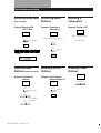
3-859-380-11(1)
Getting Started
FM Stereo
FM-AM Receiver
Operating Instructions
STR-DE310
© 1996 by Sony Corporation
1
Getting Started
WARNING
To prevent fire or shock
hazard, do not expose
the unit to rain or
moisture.
- Reorient or relocate the receiving
antenna.
- Increase the separation between the
equipment and receiver.
- Connect the equipment into an outlet
on a circuit different from that to
which the receiver is connected.
- Consult the dealer or an experienced
radio/TV technician for help.
2
• Should any solid object or liquid fall
into the cabinet, unplug the receiver
and have it checked by qualified
personnel before operating it any
further.
On power sources
You are cautioned that any change or
modifications not expressly approved in
this manual could void your authority
to operate this equipment.
• Before operating the receiver, check
that the operating voltage is identical
with your local power supply. The
operating voltage is indicated on the
nameplate at the rear of the receiver.
• The receiver is not disconnected from
the AC power source (MAINS) as
long as it is connected to the wall
outlet, even if the receiver itself has
been turned off.
• If you are not going to use the
receiver for a long time, be sure to
disconnect the receiver from the wall
outlet. To disconnect the AC power
cord, grasp the plug itself; never pull
the cord.
• One blade of the plug is wider than
the other for the purpose of safety
and will fit into the wall outlet only
one way. If you are unable to insert
the plug fully into the outlet, contact
your dealer.
• Should the AC power cord need to be
changed, have it done at a qualified
service shop only.
This reminder is provided to call the
CATV system installer’s attention to
Article 820-40 of the NEC that provides
guidelines for proper grounding and, in
particular, specifies that the cable
ground shall be connected to the
grounding system of the building, as
close to the point of cable entry as
practical.
Owner’s record
This symbol is intended to alert the user
to the presence of important operating
and maintenance (servicing)
instructions in the literature
accompanying the appliance.
The model and serial numbers are
located on the rear of the unit. Record
the serial number in the space provided
below. Refer to them whenever you call
upon your Sony dealer regarding this
product.
IMPORTANT
Model No. STR-DE310
Serial No.
This equipment has been tested and
found to comply with the limits for a
Class B digital device, pursuant to Part
15 of the FCC Rules.
These limits are designed to provide
reasonable protection against harmful
interference in a residential installation.
This equipment generates, uses, and can
radiate radio frequency energy and, if
not installed and used in accordance
with the instructions, may cause
harmful interference to radio
communications. However, there is no
guarantee that interference will not
occur in a particular installation. If this
equipment does cause harmful
interference to radio or television
reception, which can be determined by
turning the equipment off and on, the
user is encouraged to try to correct the
interference by one or more of the
following measures:
On safety
CAUTION
Note to CATV system installer
This symbol is intended to alert the user
to the presence of uninsulated
“dangerous voltage” within the
product’s
enclosure that may be of sufficient
magnitude to constitute a risk of electric
shock to persons.
Precautions
For the customers in Canada
To avoid electrical shock, do not open
the cabinet. Refer servicing to qualified
personnel only.
CAUTION:
TO PREVENT ELECTRIC SHOCK, DO
NOT USE THIS POLARIZED AC PLUG
WITH AN EXTENSION CORD,
RECEPTACLE OR OTHER OUTLET
UNLESS THE BLADES CAN BE FULLY
INSERTED TO PREVENT BLADE
EXPOSURE.
On placement
• Place the receiver in a location with
adequate ventilation to prevent heat
build-up and prolong the life of the
receiver.
• Do not place the receiver near heat
sources, or in a place subject to direct
sunlight, excessive dust or
mechanical shock.
• Do not place anything on top of the
cabinet that might block the
ventilation holes and cause
malfunctions.
On operation
• Before connecting other components,
be sure to turn off and unplug the
receiver.
On cleaning
• Clean the cabinet, panel and controls
with a soft cloth slightly moistened
with a mild detergent solution. Do
not use any type of abrasive pad,
scouring powder or solvent such as
alcohol or benzine.
Getting Started
If you have any question or problem
concerning your receiver, please
consult your nearest Sony dealer.
TABLE OF CONTENTS
Getting Started
About This Manual
The instructions in this manual describe
the controls on the receiver. You can
also use the controls on the remote if
they have the same or similar names as
those on the receiver.
• A “Quick Reference Guide” is
supplied on the back cover.
• The “Remote Button Descriptions”
section on page 15 provides an
overview of the remote buttons.
• The following icons are used in this
manual:
Indicates that you can use only
the remote to do the task.
Indicates hints and tips for
making the task easier.
Unpacking 4
Hookup Overview 4
Antenna Hookups 5
Audio/Video Component Hookups 5
Speaker System Hookups 6
AC Hookups 7
Before You Use Your Receiver 7
Receiver Operations
Selecting a Component 8
Receiving Broadcasts 9
Presetting Radio Stations 10
Recording 11
Additional Information
Troubleshooting 12
Specifications 13
Index 14
Rear Panel Descriptions 14
Remote Button Descriptions 15
Quick Reference Guide
(Back cover)
3
Getting Started
Unpacking
Hookup Overview
Check that you received the following items with the
receiver:
• FM wire antenna (1)
• AM loop antenna (1)
• Remote controller (remote) (1)
• Size AA (R6) batteries (2)
The receiver allows you to connect and control the
following audio components. Follow the hookup
procedures for the components that you want to
connect to the receiver on the pages specified. To learn
the locations and names of each jack, see “Rear Panel
Descriptions” on page 14.
Audio/Video Component
Hookups (5)
Inserting batteries into the remote
TV tuner
Insert two size AA (R6) batteries in accordance with
the + and – markings on the battery compartment.
When using the remote, point it at the remote sensor g
on the receiver.
Cable TV
AM/FM antenna
VCR
CD player
Front
speaker
(L)
]
}
Speaker
System
Hookups (6)
Antenna Hookups (5)
Tape/MD deck
Turntable
Front
speaker
(R)
}
]
When to replace batteries
Under normal use, the batteries should last for about 6
months. When the remote no longer operates the
receiver, replace both batteries with new ones.
Notes
• Do not leave the remote in an extremely hot or humid
place.
• Do not use a new battery with an old one.
• Do not expose the remote sensor to direct sunlight or
lighting apparatuses. Doing so may cause a malfunction.
• If you don’t use the remote for an extended period of time,
remove the batteries to avoid possible damage from
battery leakage and corrosion.
4
Before you get started
• Turn off the power to all components before making
any connections.
• Do not connect the AC power cords until all of the
connections are completed.
• Be sure to make connections firmly to avoid hum
and noise.
• When connecting an audio cable, be sure to match
the color-coded pins to the appropriate jacks on the
components: White (left, audio) to White; and Red
(right, audio) to Red.
Getting Started
Connecting a ground wire
Antenna Hookups
To prevent hum, connect a ground wire (not supplied)
to the y ground terminal. If you’ve connected an
outdoor antenna, be sure to connect the ground for
lightning protection.
Overview
This section describes how to connect AM and FM
antennas to the receiver. If you want to receive radio
broadcasts with the receiver, complete these
connections first, then go to the following pages.
For specific locations of the terminals, see the
illustration below.
Receiver
ANTENNA
AM
ANTENNA
.
to ground
Where do I go next?
What antennas will I need?
• FM wire antenna
(supplied) (1)
• AM loop antenna
(supplied) (1)
Audio/Video Component
Hookups
Hookups
FM wire antenna
Receiver
AM loop antenna
ANTENNA
After connecting
the wire
antenna, keep it
as horizontal as
possible.
If you want to connect other components, go on to the next
section. If you’re only planning to use the receiver to listen
to the radio, go to “Speaker System Hookups” on pages 6
and 7.
AM
FM
300
Overview
This section describes how to connect your audio, and
video (audio signal only) components to the receiver. If
you want to use the receiver as an amplifier, complete
these connections.
For specific locations of the jacks, see the illustration
below.
If you have poor FM reception
Connect a 75-ohm coaxial cable (not supplied) to an FM
outdoor antenna. Pull back the mesh portion
surrounding the inner cable and connect it to the earth
terminal (right side). Connect the inner cable to the FM
terminal (left side).
y
CD
TV
VIDEO
Receiver
ANTENNA
PHONO
FM
75
If you have poor AM reception
Connect a 20 to 50 ft. (6 to 15-meter) insulated wire (not
supplied) to the AM antenna terminal in addition to the
AM loop antenna. Try to extend the wire outdoors and
keep it horizontal.
TAPE/MD
What cords will I need?
Audio cords (not supplied) (1 for each CD player, turntable,
TV tuner or cable TV; 2 for each tape deck, MD recorder or
VCR)
White (L)
Red (R)
White (L)
Red (R)
(continued)
5
Getting Started
Hookups
Speaker System Hookups
The arrow ç indicates signal flow.
CD player
Receiver
CD player
CD
OUTPUT
IN
LINE
L
This section describes how to connect your speakers to
the receiver.
For specific locations of the terminals, see the
illustration below.
L
R
Turntable
Overview
R
Receiver
Turntable
PHONO
OUTPUT
IN
FRONT SPEAKERS A
LINE
L
L
R
R
• If your turntable has an earth lead
To prevent hum, connect the earth lead to the y ground
terminal on the receiver.
What cords will I need?
Speaker cord (not supplied) (1 for each speaker)
Tape deck or MD recorder
Tape deck or MD recorder
Receiver
TAPE/MD
REC OUT
IN
OUTPUT
INPUT
LINE
LINE
L
L
R
R
(+)
(+)
(–)
(–)
Twist the stripped ends of the cord about 2/3 inch (15 mm).
Be sure to match the speaker cord to the appropriate
terminal on the components: + to + and – to –. If the cords
are reversed, the sound will be distorted and will lack bass.
Hookups
TV tuner or Cable TV
Receiver
TV tuner or Cable TV
TV
OUTPUT
AUDIO IN
VIDEO
L
Front speakers
Front speaker
(R)
L
Front speaker
(L)
Receiver
FRONT SPEAKERS
R
R
R
}
VCR
Receiver
L
A
A
B
B
]
}
]
VCR
VIDEO
OUTPUT INPUT
AUDIO OUT AUDIO IN
AUDIO
AUDIO
L
L
R
R
If you have an additional front speaker system
Where do I go next?
Go on to the next section to connect the speakers.
6
Connect them to the FRONT SPEAKERS B terminals.
Getting Started
Selecting the speaker system
To drive the speakers, select the speaker system as
follows:
To drive
Depress SPEAKERS button
Speaker system A (connected
to the FRONT SPEAKERS A
terminals)
A
Speaker system B (connected
to the FRONT SPEAKERS B
terminals)
B
Both speaker systems A and
B (series connection)
A+B
AC Hookups
Connecting the AC power cord
Connect the AC power cord from this receiver and
from your audio/video components to a wall outlet.
If you connect other audio components to the
SWITCHED AC OUTLET on the receiver, the receiver
can supply power to the connected components so you
can turn on/off the whole system when you turn on/
off the receiver.
SWITCHED AC OUTLET
Note
No sound is heard when you press SPEAKERS A+B without
connecting speaker system B.
/
to a wall outlet
Where do I go next?
Go on to the next section to connect the AC power cord.
Caution
Make sure that the power consumption of the component
connected to the receiver’s AC outlet does not exceed 120
watts. Do not connect high-wattage electrical home
appliances such as electric irons, fans, or TVs to this outlet.
Where do I go next?
Before you use the receiver, go to the next section to make
sure that all the controls are set to the appropriate positions.
Before You Use Your Receiver
Before you start using your receiver, make sure that
you have:
• Turned VOLUME to the leftmost position (0).
• Selected the appropriate speaker system. (See
“Selecting the speaker system” on this page.)
• Set BALANCE to the center position.
Turn on the receiver and check the following display.
• Press MUTING on the remote if the MUTING is
displayed.
7
Receiver Operations
Selecting a Component
To listen to a connected component, first select the
function on the receiver or with the remote.
Before you begin, make sure you have:
• Connected all components securely and correctly as
indicated on pages 5 to 7.
• Turned VOLUME to the leftmost position (0) to
avoid damaging your speakers.
POWER
To
Do this
Mute the sound
Press MUTING on the remote.
Press again to restore the
sound
Reinforce the bass
Press BASS BOOST to turn on
the BASS BOOST indicator.
Adjust the balance
Turn the BALANCE control
left or right.
Adjust the tone quality
Adjust the BASS and TREBLE
controls.
VOLUME
When you listen with headphones
Connect the headphones to the PHONES jack and set
the SPEAKERS buttons to OFF.
To turn off the components
Press POWER. You can turn off the video and audio
components connected to the SWITCHED AC OUTLET at
the same time.
Function buttons
9
(
0
)
p
POWER
FUNCTION
VOL +/–
(
=
8
P
p
+
1
Press POWER to turn on the receiver.
2
Press a function button to select the component
you want to use:
To listen to or watch
Press
Records
PHONO
Radio programs
TUNER
Compact discs (CD)
CD
Audio tapes or MiniDiscs
(MD)
TAPE/MD
TV programs or Cable TV
TV
Video tapes
VIDEO
3
Turn on the component, for example, a CD player,
and then start playing.
To tune in radio stations on this receiver, see
“Receiving Broadcasts” on page 9.
4
Turn VOLUME or press VOL +/– on the remote
to adjust the volume.
Receiver Operations
If an FM stereo program is distorted
Receiving Broadcasts
The STEREO indicator flashes. Press FM MODE to
change to monaural (MONO). You will not have the
stereo effect but the distortion will be reduced. To
return to stereo mode, press this button again.
This receiver lets you enter a station’s frequency
directly by using the numeric buttons (direct tuning). If
you don’t know the frequency of the station you want,
see “Receiving broadcasts by scanning stations
(automatic tuning)” on this page.
If you cannot tune in a station and the entered
numbers are flashing
Make sure you’ve entered the right frequency. If not,
press DIRECT and re-enter the frequency you want.
If the entered numbers still flash, the frequency is not
used in your area.
Before you begin, make sure you have:
• Connected an FM/AM antenna to the receiver as
indicated on page 5.
• Selected the appropriate speaker system. (See
“Selecting the speaker system” on page 7.)
POWER
Numeric buttons
To watch FM simulcast TV programs
Make sure that you tune in the simulcast program both
on the TV (or the VCR) and on the receiver.
VOLUME
If you enter a frequency not covered by the tuning
interval
The entered value is automatically rounded up or down
to the closest covered value.
DIRECT
TUNER
TUNING
+/–
Tuning intervals for direct tuning are:
FM: 50 kHz intervals
AM: 10 kHz intervals (to change to 9 kHz intervals, see
page 13)
FM/AM
1
Press POWER to turn on the receiver.
2
Press TUNER.
The last received station is tuned in.
Receiving broadcasts by scanning stations
(automatic tuning)
3
Press FM/AM to select FM or AM stations.
4
Press DIRECT.
If you don’t know the frequency of the radio station
you want, you can have the receiver scan all the
receivable stations to locate the one you want.
5
Press the numeric buttons to enter the frequency.
1
Press TUNER.
The last received station is tuned in.
2
Press FM/AM to select FM or AM.
3
Press TUNING + or –.
Press the + button for a higher station number;
press the – button for a lower one. When you tune
past either end of the band, the receiver
automatically jumps to the opposite end. Every
time a station is received, the receiver stops
scanning. To continue scanning, press the button
again.
Example 1: FM 102.50 MHz Example 2: AM 1350 kHz
1
0
2
5
0
(You don’t have to enter
the last “0.”)
1
6
3
5
When you tune in AM stations, adjust the
direction of the AM loop antenna for optimum
reception.
To receive other stations
Repeat Steps 3 to 5.
If the STEREO indicator remains off
Press FM MODE when an FM stereo broadcast is
received.
9
Receiver Operations
Presetting Radio Stations
You’ll most likely want to preset the receiver with the
radio stations you listen to often so that you don’t have
to tune in the station every time. The receiver can store
a total of 30 FM or AM stations. You can store the
stations on preset numbers combining 3 characters (A,
B, C) and numbers (0 - 9). For example, you can store a
station as preset number A1, B6 or C9, etc.
SHIFT
Numeric buttons
Tuning preset stations (preset tuning)
You can tune directly to a preset station by entering its
preset number. If you don’t know which stations are
preset on which numbers, you can tune by scanning
the preset stations.
1
Press TUNER.
The last received station is tuned in.
2
Press SHIFT to select a character (A, B or C), then
press the number.
For example, select A and then press 7 to tune in
the station preset as A7.
You can tune by scanning the preset stations
First press TUNER and then press PRESET TUNING +
or – to select the station you want. Each time you press
the buttons, the preset numbers change as follows:
TUNER
MEMORY
1
Press TUNER.
The last received station is tuned in.
2
Tune in the station you want.
If you are not familiar with how to tune in a
station, see “Receiving Broadcasts” on the
previous page.
3
Press MEMORY.
“MEMORY” appears for a few seconds.
Do steps 4 and 5 before “MEMORY” goes out.
4
Press SHIFT to select a character (A, B or C).
Each time you press SHIFT, the letter “A,” “B” or
“C” appears in the display.
If “MEMORY” disappears, start again from step 3.
5
While MEMORY is displayed, press the number
you want to use (0 to 9).
6
Repeat Steps 2 to 5 to preset other stations.
To change a preset station
Preset a new station on the number you want to change.
Note
If the AC power cord is disconnected for about one week,
the preset stations will be cleared from the receiver’s
memory, and you will have to preset the stations again.
10
n A1 ˜ A2 ˜… ˜ A0 ˜ B1 ˜ B2 ˜ … ˜ B0 N
n C0 ˜ … ˜ C2 ˜ C1N
Receiver Operations
Recording
This receiver makes it easy to record to and from the
components connected to the receiver. You don’t have
to connect playback and recording components
directly: once you select a program source on the
receiver, you can record and edit as you normally
would using the controls on each component.
Before you begin, make sure you’ve connected all
components properly.
Function buttons
ç
ç
Playback component
(program source)
Recording component
(Tape deck, MD recorder,
VCR)
ç: Audio signal flow
Recording on an audio tape, MiniDisc or
video tape
You can record audio on a cassette tape, MiniDisc or
video tape using the receiver. See the instruction
manual of your tape deck, MD recorder or VCR if you
need help.
1
Press one of the function buttons to select the
program source.
2
Set the component to be ready for playing.
For example, insert a CD into the CD player.
3
Insert a blank tape or disc into the recording deck
and adjust the recording level, if necessary.
4
Start recording on the recording deck and then
start playing the component.
11
Additional Information
Troubleshooting
If you experience any of the following difficulties while
using the receiver, use this troubleshooting guide to
help you remedy the problem. Should any problem
persist, consult your nearest Sony dealer.
There’s no sound or only a very low-level sound is heard.
/
Check that the speakers and components are
connected securely.
/
Make sure you select the correct component
on the receiver.
/
Make sure you set the SPEAKERS selector
correctly.
/
Press MUTING on the remote if the MUTING
indicator turns on.
/
The protective device on the receiver has been
activated because of a short circuit.
(“PROTECT” flashes.) Turn off the receiver,
eliminate the short-circuit problem and turn
on the power again.
The left and right sounds are unbalanced or reversed.
/
Check that the speakers and components are
connected correctly and securely.
/
Adjust the BALANCE control.
Severe hum or noise is heard.
/
Check that the speakers and components are
connected securely.
/
Check that the connecting cords are away
from a transformer or motor, and at least 10
feet (3 meters) away from a TV set or
fluorescent light.
/
Place your TV away from the audio
components.
/
Make sure you connect a ground wire to the
antenna ground terminal.
/
The plugs and jacks are dirty. Wipe them
with a cloth slightly moistened with alcohol.
Radio stations cannot be tuned in.
/
Check that the antennas are connected
securely. Adjust the antennas and connect an
outdoor antenna if necessary.
/
The signal strength of the stations is too weak
(when you tune in with automatic tuning).
Use direct tuning.
/
Make sure you set the tuning interval
correctly (when you tune in AM stations with
automatic tuning) (see pages 9 and 13).
/
No stations have been preset or the preset
stations have been cleared (when you tune in
with scanning preset stations). Preset the
stations (see page 10).
12
No picture or an unclear picture is seen on the TV screen.
/
Place your TV away from the audio
components.
Recording cannot be made.
/
Check that the components are connected
correctly.
The remote does not function.
/
Point the remote at the remote sensor g on
the receiver.
/
Remove the obstacles in the path of the
remote and the receiver.
/
Replace both batteries in the remote with new
ones if they are weak.
/
Make sure you select the correct function on
the remote.
Additional Information
Outputs
Specifications
Audio power specifications
POWER OUTPUT AND TOTAL
HARMONIC DISTORTION
With 8-ohm load, both
channels driven, from 20 20,000 Hz, rated 100 watts
per channel minimum RMS
power, with no more than
0.1 % total harmonic
distortion from 250
milliwatts to rated output.
Amplifier section
Dynamic power USA model:
output
8 ohms: 150 W + 150 W
4 ohms: 210 W + 210 W
Canadian model:
8 ohms: 140 W + 140 W
4 ohms: 180 W + 180 W
Frequency
response
PHONO: RIAA
equalization curve
±0.5 dB
CD, TAPE/MD, VIDEO:
10 Hz - 50 kHz ±1 dB
Inputs
Sensitivity
PHONO
(MM)
CD
TAPE/
MD,
TV,
VIDEO
2.5 mV
Impedance
50
kilohms
S/N
(weighting
network,
input level)
74 dB
72 dB*
(A, 2.5 mV)
200 mV
150 mV
50
kilohms
82 dB
82 dB*
(A, 150 mV)
* ‘78 IHF
TAPE/MD REC OUT:
Voltage 150 mV,
Impedance 10 kilohms
VIDEO AUDIO OUT:
Voltage 150 mV,
Impedance 10 kilohms
PHONES: Accepts low
and high impedance
headphones
Muting
Full mute
BASS BOOST
+10 dB at 70 Hz
TONE
±8 dB at 100 Hz and
10 kHz
FM tuner section
Tuning range
87.5 - 108.0 MHz
Antenna
terminals
75 ohms, unbalanced
300 ohms, unbalanced
Sensitivity
Mono: 18.3 dBf, 4.5 µV
Stereo: 38.3 dBf, 45 µV
Usable sensitivity 11.2 dBf, 2 µV (IHF)
S/N
Mono: 76 dB
Stereo: 70 dB
Harmonic
distortion at
1 kHz
Mono: 0.3 %
Stereo: 0.5 %
Separation
45 dB at 1 kHz
Frequency
response
30 Hz - 15 kHz
Selectivity
60 dB at 400 kHz
General
System
Tuner section: PLL
quartz-locked digital
synthesizer system
Preamplifier section:
Low-noise NF type
equalizer
Power amplifier section:
Pure-complimentary
SEPP
Power
requirements
120 V AC, 60 Hz
Power
consumption
USA model: 175 W
Canadian model: 270 AV
AC outlets
1 switched, total 120 W/
1A Max
Dimensions
17 x 5 3/4 x 11 5/8 inches
(430 x 145 x 295 mm)
Mass (Approx.)
7.0 kg (15 lb 6 oz)
Supplied
accessories
FM wire antenna (1)
AM loop antenna (1)
Remote controller
(remote) (1)
Size AA (R6) batteries (2)
Design and specifications are subject to
change without notice.
+0.5
–2
dB
AM tuner section
Tuning range
With 10 kHz interval**:
530 - 1710 kHz
With 9 kHz interval:
531 - 1710 kHz
Antenna
Loop antenna
Usable sensitivity 50 dB/m (at 1,000 kHz or
999 kHz)
S/N
54 dB (at 50 mV/m)
Harmonic
distortion
0.5 % (50 mV/m,
400 Hz)
Selectivity
At 9 kHz: 35 dB
At 10 kHz: 40 dB
** You can change the AM tuning interval
to 9 kHz. After tuning in any AM station,
turn off the receiver. Hold down the
TUNING + button and press the POWER
button. All preset stations will be erased
when you change the interval. To reset
the interval to 10 kHz, repeat the
procedure.
13
Index
A, B
S
P
Adjusting
tone 8
volume 8
Antenna hookups 5
Audio/video component
hookups 5, 6
Automatic tuning 9
Scanning
preset stations 10
radio stations 9
Selecting a program source 8
Speakers
connection 6, 7
impedance 13
selecting speaker system 7
Storing radio stations. See
Presetting
Presetting
radio stations 10
Preset tuning 10
Program source
selecting 8
Q
Quick reference guide
Back cover
C
Connecting. See Hookups
R
D
Rear panel 5, 6, 7, 14
Receiving broadcasts
directly 9
using preset stations 10
Recording
on a tape, MiniDisc or video
tape 11
Remote buttons 8, 15
Direct tuning 9
Dubbing. See Recording
E, F, G
Editing. See Recording
H, I, J, K, L, M, N, O
T
Troubleshooting 12
Tuning. See Receiving
broadcasts
U, V, W, X, Y, Z
Unpacking 4
Hookups
AC power cord 7
antennas 5
audio/video components 5,
6
overview 4
speakers 6, 7
Rear Panel Descriptions
1
2
3 4 5
6 7
8
0
1 ANTENNA (AM/FM)
2 y ground terminal
3 PHONO
4 CD
14
5 TAPE/MD
6 TV
7 VIDEO
9
8 AC power cord
9 SWITCHED AC OUTLET
0 FRONT SPEAKERS (A/B)
Remote Button Descriptions
For buttons not described on previous pages and
buttons with names different from the buttons on the
main unit.
Remote
Button
Operates
Function
PRESET +/–
Receiver
Scans and selects preset
stations.
D. SKIP
CD player
Skips discs (CD player
with multi-disc changer
only.)
0
/
)
Tape deck
Fastforwards or rewinds.
=
/
+
CD player/
MD recorder
Skips tracks.
P
CD player/MD Pauses play or record.
recorder
(Also starts recording
with components in
record standby.)
(
CD player/
Starts play.
Tape deck/MD
recorder
p
CD player/
Stops play.
Tape deck/MD
recorder
9
Tape deck
Starts play on the reverse
side.
15
Quick Reference Guide
Receiving Broadcasts Presetting Radio
Stations
(direct tuning)
Example: Presetting a
station as A7
Example: Receiving FM
102.50 MHz
Selecting a
Component
Example: Playing a CD
CD
TUNER
TUNER
v
v
v
FM/AM
Tune in the station you want.
v
v
Start playing.
Select FM.
v
Turn on the CD player.
MEMORY
DIRECT
v
v
1
0
SHIFT
2
5
Select A.
0
v
Display
7
MHz
Scanning Radio
Receiving Preset
Stations (automatic tuning) Stations
Example: Scanning FM
stations
v
v
FM/AM
SHIFT
v
v
TUNING
v
–
Sony Corporation
16
TUNING
Printed in China
+
To continue
scanning.
+
7
v
–
Select A.
Select FM.
–
TUNER
Example: Receiving the
station number A7
TUNER
TUNER
Scanning Preset
Stations
PRESET TUNING +